JP5113420B2 - Transformer - Google Patents
Transformer Download PDFInfo
- Publication number
- JP5113420B2 JP5113420B2 JP2007131914A JP2007131914A JP5113420B2 JP 5113420 B2 JP5113420 B2 JP 5113420B2 JP 2007131914 A JP2007131914 A JP 2007131914A JP 2007131914 A JP2007131914 A JP 2007131914A JP 5113420 B2 JP5113420 B2 JP 5113420B2
- Authority
- JP
- Japan
- Prior art keywords
- plane
- piece
- coil support
- support piece
- transformer
- Prior art date
- Legal status (The legal status is an assumption and is not a legal conclusion. Google has not performed a legal analysis and makes no representation as to the accuracy of the status listed.)
- Active
Links
Images


Classifications
-
- H—ELECTRICITY
- H01—ELECTRIC ELEMENTS
- H01F—MAGNETS; INDUCTANCES; TRANSFORMERS; SELECTION OF MATERIALS FOR THEIR MAGNETIC PROPERTIES
- H01F27/00—Details of transformers or inductances, in general
- H01F27/06—Mounting, supporting or suspending transformers, reactors or choke coils not being of the signal type
-
- H—ELECTRICITY
- H01—ELECTRIC ELEMENTS
- H01F—MAGNETS; INDUCTANCES; TRANSFORMERS; SELECTION OF MATERIALS FOR THEIR MAGNETIC PROPERTIES
- H01F27/00—Details of transformers or inductances, in general
- H01F27/24—Magnetic cores
- H01F27/25—Magnetic cores made from strips or ribbons
-
- H—ELECTRICITY
- H01—ELECTRIC ELEMENTS
- H01F—MAGNETS; INDUCTANCES; TRANSFORMERS; SELECTION OF MATERIALS FOR THEIR MAGNETIC PROPERTIES
- H01F27/00—Details of transformers or inductances, in general
- H01F27/24—Magnetic cores
- H01F27/26—Fastening parts of the core together; Fastening or mounting the core on casing or support
- H01F27/266—Fastening or mounting the core on casing or support
Landscapes
- Engineering & Computer Science (AREA)
- Power Engineering (AREA)
- Housings And Mounting Of Transformers (AREA)
- Coils Or Transformers For Communication (AREA)
- Coils Of Transformers For General Uses (AREA)
Description
本発明は、変圧器に係り、特に、変圧器本体を支持する構成に関する。 The present invention relates to a transformer, and more particularly to a configuration for supporting a transformer body.
従来、例えば、油入変圧器では、変圧器本体が、コアの底部側に配した箱状の支持体(下部片)の中に該コアの底部及びコイル支持片を入れて支持する構成のものが使用されている。該箱状の下部片は、その底面部でコアの底部下面及びコイル支持片の端面を支持し、該底面部の周囲の閉じた4側面部で該コアの底部側面及びコイル支持片の下方部分を覆っている。
また、本発明に関連した従来技術であって、特許文献に記載された技術としては、例えば、特開平11−162752号公報(特許文献1)に記載されたものがある。該特開平11−162752号公報には、変圧器の巻線支持装置として、鉄心(コア)の上下継鉄部を、上下方向から嵌合治具10、10aで嵌合支持する構成とし、該嵌合治具10、10aを、隅角部に垂直な係合溝12、12aを設けた一対の締付金具13、13aと、該係合溝12、12aに係合され、鉄心の脚鉄部に巻き回した巻線5を軸方向に押圧固定する巻線支持片11、11aとから形成するとした構成が記載されている。
2. Description of the Related Art Conventionally, for example, in an oil-filled transformer, the transformer body is configured to support the core bottom portion and coil support piece in a box-like support (lower piece) disposed on the bottom side of the core. Is used. The box-shaped lower piece supports the bottom surface of the bottom of the core and the end surface of the coil support piece at the bottom surface thereof, and the bottom side surface of the core and the lower portion of the coil support piece at four closed side surfaces around the bottom surface portion. Covering.
Further, as a related art related to the present invention, there is a technique described in Japanese Patent Laid-Open No. 11-162752 (Patent Document 1), for example. In Japanese Patent Laid-Open No. 11-162752, as a winding support device for a transformer, the upper and lower yoke portions of an iron core (core) are fitted and supported by
上記従来技術のうち、変圧器本体を箱状の支持体(下部片)で支持する構成では、該支持体の4側面部が閉じているため、タンク内の油液が該箱状の支持体の内部で流動しにくく、コア自体で発生した熱またはコイルからコアに伝わった熱の油液中への放熱量が低下し、油液の冷却効果が下がるおそれがある。また、該箱状の支持体はコイル支持片を収納可能な寸法が必要であり、寸法及び重量が増大し易い。支持体の寸法及び重量の増大は、油入変圧器全体の寸法及び重量の増大の原因になる。また、上記特開平11―162752号公報記載の技術は、巻線支持片11、11aを、締付金具13、13aの係合溝12、12aに係合させる構成であり、かつ、嵌合治具10、10aを設ける構成であるため、変圧器本体の支持部の構成が複雑となり、組立て作業にも時間がかかり、コストの増大につながるおそれがある。
Among the prior arts described above, in the configuration in which the transformer body is supported by the box-shaped support (lower piece), the four side surfaces of the support are closed, so that the oil in the tank is transferred to the box-shaped support. It is difficult to flow inside, and the amount of heat generated in the core itself or the heat transmitted from the coil to the core into the oil liquid is reduced, and the cooling effect of the oil liquid may be reduced. In addition, the box-like support body needs to have a size capable of accommodating the coil support piece, and the size and weight are likely to increase. An increase in the size and weight of the support causes an increase in the overall size and weight of the oil-filled transformer. Further, the technique described in the above-mentioned Japanese Patent Application Laid-Open No. 11-162752 has a configuration in which the winding support pieces 11 and 11a are engaged with the engagement grooves 12 and 12a of the fastening fittings 13 and 13a, and the fitting treatment is performed. Since it is the structure which provides the
本発明の課題点は、上記従来技術の状況に鑑み、変圧器において、変圧器本体を支える支持部材を、寸法や重量の増大を抑えた製作し易い簡易構成とすることである。
本発明の目的は、上記課題点を解決し、生産性が良い変圧器を提供することにある。
The subject of this invention is making it the simple structure which is easy to manufacture in the transformer which suppressed the increase in a dimension and a weight in the transformer in the transformer in view of the situation of the said prior art.
An object of the present invention is to solve the above problems and provide a transformer with high productivity.
上記課題点を解決するために、本発明では、タンク内の油液中において変圧器本体が支持される構成の変圧器として、コア上方に上部片、コイル下方に平板状のコイル支持片、コア底部側に下部片をそれぞれ設け、該上部片と該下部片とをコアの幅方向平面側で短冊状の連結部材で連結する構成とし、特に、該下部片を、上記コアの底部及び上記コイル支持片の端面を支持する底面部と、該底面部の互いに直交する4方向に形成され上記コイル支持片に拘束力を作用させる側面部とを有し、該側面部が、その平面の先端側の辺長を該平面の根元側の辺長よりも短くされ、このうち、上記コイル支持片の平面に沿った2個の対向する一方の側面部がそれぞれ、その平面が該コイル支持片の外側において該コイル支持片の平面に対し傾斜し、該一方の側面部の内面側の先端部が該コイル支持片の平面に当接した状態で該一方の側面部と該コイル支持片との間に、該一方の側面部の先端側の辺または根元側の辺に沿う方向に貫通した隙間を形成し、該隙間を通した上記油液の流動を可能とし、また、2個の対向する他方の側面部はそれぞれが該コイル支持片の対向面間に設けられた構成とする。 In order to solve the above-described problems, in the present invention, as a transformer configured to support a transformer body in oil liquid in a tank, an upper piece above the core, a flat coil support piece below the coil, a core A lower piece is provided on the bottom side, and the upper piece and the lower piece are connected to each other by a strip-like connecting member on the plane in the width direction of the core. In particular, the lower piece is connected to the bottom of the core and the coil. A bottom surface portion for supporting the end surface of the support piece; and a side surface portion that is formed in four directions orthogonal to the bottom surface portion and acts to restrain the coil support piece, and the side surface portion is on a front end side of the plane. The side length of the plane is shorter than the side length on the base side of the plane, and of these, two opposing side surfaces along the plane of the coil support piece each have a plane that is outside the coil support piece. And inclined with respect to the plane of the coil support piece. The side or root side of the one side portion between the one side portion and the coil support piece in a state in which the tip portion on the inner surface side of the side portion is in contact with the plane of the coil support piece Forming a gap penetrating in the direction along the side of the coil, allowing the oil liquid to flow through the gap, and each of the other two opposite side faces between the opposed faces of the coil support piece. It is set as the provided structure.
本発明によれば、生産性が良い変圧器を提供することができる。 According to the present invention, a transformer with good productivity can be provided.
以下、本発明の実施例につき、図面を用いて説明する。
図1〜図6は、本発明の実施例の説明図である。図1は、本発明の実施例としての変圧器の構成例を示す図、図2は、図1の変圧器の正面図、図3は、図1の変圧器における変圧器本体の支持部材による支持状態を示す斜視図、図4は、図1の変圧器における変圧器本体の支持部材による支持状態を示す側面図、図5は、図1の変圧器における支持部材の効果の説明図、図6は、図1の変圧器における支持部材の下部片の製造手順の説明図である。本実施例では、変圧器が油入変圧器である場合につき説明する。
Embodiments of the present invention will be described below with reference to the drawings.
1-6 is explanatory drawing of the Example of this invention. 1 is a diagram showing a configuration example of a transformer as an embodiment of the present invention, FIG. 2 is a front view of the transformer of FIG. 1, and FIG. 3 is a support member of a transformer body in the transformer of FIG. FIG. 4 is a side view showing a support state by a support member of the transformer main body in the transformer of FIG. 1, FIG. 5 is an explanatory view of the effect of the support member in the transformer of FIG. 6 is an explanatory diagram of a manufacturing procedure of a lower piece of a support member in the transformer of FIG. 1. In this embodiment, the case where the transformer is an oil-filled transformer will be described.
図1において、100は、本発明の実施例としての油入変圧器、10はタンク、1は、油入変圧器100の変圧器本体において磁路を形成する環状のコア、2a、2bはそれぞれ、コア1に巻装され、該コア1とともに変圧器本体を構成するコイルであって、2aは1次側コイル、2bは2次側コイルである。また、3は、コア1の天頂部の上方に配されコ字状断面を有し該天頂部を覆う上部片、6a、6bはそれぞれ、非磁性の絶縁材で構成され、コイル2a、2bの下側端面の下方において、コア1の厚さ方向の平面(ZX平面)1b1、1b2に沿い該コア1をはさんでその両側に配され、該コイル2a、2bの下側端面を支持する平板状のコイル支持片(コイル支持片6aはコア1に対しその厚さ方向の平面1b1側に配され、コイル支持片6bはコア1に対しその厚さ方向の平面1b2側に配される)、4は、コア1の底部側に配され該コア1の底部及び上記コイル支持片6a、6bの端面を支持する下部片である。該下部片4は、略四角形状の底面部と、該底面部の四方に該底面部に連続して形成されその平面を上記コイル2a、2bの下側端面方向に向けられ、かつ、該平面の先端側の辺長が、該底面部に連続する該平面の根元側の辺長よりも短くされたまたは隣接する辺間に隙間が形成された4個の側面部とを有して成る。該4個の側面部のうち、対向する一方の2個の側面部はそれぞれが、その平面を該コイル支持片6a、6bの平面に沿わせて該コイル支持片6a、6bの外側に設けられ、対向する他方の2個の側面部はそれぞれが、その平面を該コイル支持片6a、6bそれぞれの平面に対し略直角にして該コイル支持片6a、6bの対向面間に設けられる。5a、5bは、短冊状の連結部材であって、上記コイル該コイル2a、2bの外側にあって上記コア1の幅方向の平面(YZ平面)1a1、1a2に沿って配され、上記上部片3と上記下部片4の上記他方の2個の側面部との間を連結する。7aは、連結部材5aを上部片3に結合するボルト、7bは、連結部材5bを上部片3に結合するボルト、7cは、連結部材5bを下部片4に結合するボルトである。上記上部片3、上記コイル支持片6a、6b、上記下部片4、上記連結部材5a、5b及ぶ上記ボルトは、変圧器本体を支持する支持部材を構成する。コイル支持片6a、6bは、例えば木材や樹脂材を用いて構成し、上部片3や下部片4や連結部材5a、5bは、例えば鋼材を用いて構成する。
In FIG. 1, 100 is an oil-filled transformer as an embodiment of the present invention, 10 is a tank, 1 is an annular core that forms a magnetic path in the transformer body of the oil-filled
上記下部片4において、4個の側面部のうち、上記対向する一方の2個の側面部のうちの1つである側面部4aの場合、その平面の先端4atの辺長Watが、該平面の根元4abの辺長Wabよりも短くされ、かつ、該辺長Wabが、コイル支持片6aのX軸方向の長さWs1よりも短くされている。本実施例では、側面部4aは台形形状であり、先端4atは台形の頂部、根元4abは台形の底部を形成し、先端4atと根元4abとを結ぶ部分4a1、4a2は直線状の斜辺をそれぞれ形成している。図1には示されないが、側面部4aに対向する側面部の場合も、該側面部4aと同様、平面の先端の辺長が、該平面の根元の辺長よりも短くされ、かつ、該平面の根元の辺長が、コイル支持片6bのX軸方向の長さよりも短くされ、本実施例の場合、該平面は台形形状とされている。該4個の側面部のうち、コイル支持片6a、6bの対向面間に設ける上記対向する他方の2個の側面部(側面部4dとこれに対向する側面部)もそれぞれ、平面の先端の辺長が、該平面の根元の辺長よりも短くされ、本実施例の場合、台形形状とされている。かかる構成により、各側面部の隣接する辺(斜辺)間には隙間が形成される。
以下、説明中で用いる図1中の構成要素には、図1の場合と同じ符号を付して用いる。
In the
In the following description, the same reference numerals as those in FIG. 1 are used for the components in FIG. 1 used in the description.
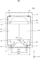
図2は、図1の油入変圧器100の正面図(ZX平面図)である。
図2において、4c、4dは、上記下部片4においてコイル支持片6a、6bの対向面間に設ける上記対向する他方の2個の側面部であって、4cは、コア1の幅方向の平面(YZ平面)1a1側に配される側面部、4dは、コア1の幅方向の平面(YZ平面)1a2側に配される側面部である。また、7dは、連結部材5aを下部片4の側面部4cに結合するボルトである。他の符号は、図1の場合と同じである。側面部4c、4d間の距離Wcdは、側面部4aの平面の根元4abの辺長Wabよりも長くされ、コイル支持片6aのX軸方向の長さWs1は、該側面部4c、4d間の距離Wcdよりも長くされている。側面部4c、4dと、側面部4aと対向する側面部及びコイル支持片6aとの関係もこれと同様である。
以下、説明中で用いる図2中の構成要素には、図2の場合と同じ符号を付して用いる。
FIG. 2 is a front view (ZX plan view) of the oil-filled
In FIG. 2, 4 c and 4 d are the other two side surfaces facing each other provided between the opposing surfaces of the
In the following description, the components in FIG. 2 used in the description are used with the same reference numerals as in FIG.
図3は、図1の油入変圧器100における変圧器本体の支持部材による支持状態を示す斜視図である。図3において、4eは、下部片4の底面部である。
以下、説明中で用いる図3中の構成要素には、図3の場合と同じ符号を付して用いる。
FIG. 3 is a perspective view showing a support state of the transformer body in the oil-filled
Hereinafter, the same reference numerals as those in FIG. 3 are used for the components in FIG. 3 used in the description.
図4は、図1の油入変圧器100における変圧器本体の支持部材による支持状態を示す側面図である。
図4において、4bは、下部片4において側面部4aに対向する側面部、4btは、該側面部4bの先端、4bbは、該側面部4bの根元である。また、4d1、4d2はそれぞれ、側面部4dの先端4dtと該根元4dbとを結ぶ部分(以下、傾斜部という)である。本実施例では、側面部4dも台形形状であり、先端4dtは台形の頂部、根元4dbは台形の底部を形成し、傾斜部4d1、4d2はそれぞれが直線状の斜辺を形成している。また、haは、側面部4aのZ軸方向の高さ、hbは、側面部4bのZ軸方向の高さ、hdは、側面部4dのZ軸方向の高さ、Ws3は、コイル支持片6a、6bの対向面間距離、4d10は、側面部4dの傾斜部4d1の根元4db寄り部分であってコイル支持片6aと接する部分、4d20は、側面部4dの傾斜部4d2の根元4db寄り部分であってコイル支持片6bと接する部分、θaは、側面部4aが底面部4eと成す角、θbは、側面部4bが底面部4eと成す角である。
FIG. 4 is a side view showing a support state of the transformer body in the oil-filled
In FIG. 4, 4b is a side portion opposite to the
図4において、側面部4dの根元の辺長Wd b は、コイル支持片6a、6bの対向面間距離Ws3よりも長くされている。側面部4dの場合も同様である。また、側面部4a、4bの各高さha、hbは、互いに略同じ高さ寸法とされ、側面部4dの高さhdよりも高くされている。また、同様に、該高さha、hbは、側面部4dに対向した側面部4cの高さ寸法よりも高くされている(側面部4dの高さhdと側面部4cの高さは略同じであるとする)。
4, the side length Wd b of the
側面部4dの傾斜部4d1がコイル支持片6aと接する部分4d10では、傾斜部4d1がコイル支持片6a中に食い込んだ状態となり、同様に、傾斜部4d2がコイル支持片6bと接する部分4d20では、傾斜部4d2がコイル支持片6b中に食い込んだ状態となっている。かかる状態にされることで、コイル支持片6a、6bはそれぞれ、下部片4に対して固定される。
In part 4d 10
また、角θa、θbはそれぞれ、下部片4の側面部4aの根元4abの角部ca、側面部4bの根元4bbの角部cbにおける曲率半径Rに対応した値例えば70°〜85°の範囲内の値とする。側面部4aは、かかる角θaを成した状態でその内面の先端4atの近傍がコイル支持片6aの平面に当接し、該コイル支持片6aを支持する。このとき、コイル支持片6aの下端面は、側面部4aの根元4abの角部caにさしかかる直前部に位置する。同様に、側面部4bは、角θbを成した状態でその内面の先端4btの近傍がコイル支持片6bの平面に当接し、該コイル支持片6bを支持する。このとき、コイル支持片6bの下端面は、側面部4bの根元4bbの角部cbにさしかかる直前部に位置する。角θa、θbをさらに小さくした場合には、下部片4の底面部4eのY軸方向寸法が増大し、支持部材全体の重量や寸法を増大させる。側面部4a、4bがそれぞれ、90°よりも小さい角θa、θbを成すことにより、コイル支持片6aと側面部4aとの間及びコイル支持片6bと側面部4bとの間にはそれぞれ、隙間Sa、Sbが形成される。該隙間Sa、Sbは、X軸方向に貫通し、かつ隣接した側面部間すなわち4a−4c間、4a−4d間、4b−4c間、4b−4d間の各隣接する斜辺間に形成された隙間に通じている空間であり、タンク10内における該X軸方向(±X軸方向)への油液の流動を可能にする。
Also, angle theta a, theta b respectively, the corner portion c a root 4ab of the
側面部4a、4bがそれぞれ、底面部4eに対し直立している場合(以下、この場合の側面部4a、4bを側面部4a'、4b'という)には、図5に示すように、側面部4a'、4b'は、コイル支持片6a、6bとの間に隙間ga、gbを形成し、該コイル支持片6a、6bには当接しない。このため、該側面部4a'、4b'は、コイル支持片6a、6bに対して拘束力を作用させず、コイル支持片6a、6bは変圧器本体とともに傾斜変位し易くなる。図5中、6b'は、傾斜変位したときのコイル支持片6bを示す。これに対し、図1の油入変圧器100においては、図4に示したように、側面部4a、4bはそれぞれ、90°よりも小さい角θa、θbを成すように底面部4eに対する直立方向から傾斜しているために、コイル支持片6a、6bにそれぞれの先端4at、4btの近傍で当接し、上記隙間Sa、Sbを形成した状態で該コイル支持片6a、6bを拘束する。これによって、コイル支持片6a、6bは傾斜変位を回避される。
When the
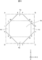
図6は、図1の油入変圧器100における支持部材の下部片4の製造手順の説明図である。
先ず、下部片4の寸法に対応した寸法の四角形ABCDの鋼板を準備し、次に、この鋼板の四隅を三角形状に切除(三角形AEL、三角形BGF、三角形CIH及び三角形DKJを切除する)して8角形EFGHIJKLを形成する。次に、該8角形EFGHIJKLを、直線MN、直線OP、直線QR及び直線STの各部分で折り曲げ、辺EF、辺GH、辺IJ及び辺KLをそれぞれZ軸方向側に向け、平面EFNMが、平面MNOPQRSTに対し角θaを成し、平面IJRQが、平面MNOPQRSTに対し角θbを成すようにする。上記直線MN、直線OP、直線QR及び直線STは、上記各側面部4a、4c、4b、4dの高さ寸法及び底面部4eの平面寸法が確保される位置に設定されているとする。これにより、平面MNOPQRST(本実施例では該平面MNOPQRSTの形状を略四角形状という)を底面部4e、平面EFNMを側面部4a、平面IJRQを側面部4b、平面GHPOを側面部4c、平面KLTSを側面部4dとした下部片4が構成される。平面EFNMにおける辺FNは側面部4aの斜辺4a1に、辺EMは斜辺4a2に、辺EFは先端4atに、辺MNは根元4abにそれぞれ該当し、平面KLTSにおける辺LTは側面部4dの斜辺4d1に、辺KSは斜辺4d2に、辺KLは先端4dtに、辺STは根元4dbにそれぞれ該当する。平面IJRQ、平面GHPOについても同様である。また、互いに隣接する2辺間、すなわち辺FNと辺GOとの間、辺HPと辺IQとの間、辺JRと辺KSとの間、辺LTと辺EMとの間にはそれぞれ隙間が形成される。このようにして、下部片4が容易に製作される。
FIG. 6 is an explanatory diagram of a manufacturing procedure of the
First, a square ABCD steel plate having a size corresponding to the size of the
上記図1〜図6で説明した実施例によれば、生産性が良く、油液の流動を確保し有効な冷却及び絶縁を行うことができる油入変圧器を提供することができる。 According to the embodiment described with reference to FIGS. 1 to 6, it is possible to provide an oil-filled transformer that has good productivity, ensures fluid flow, and can perform effective cooling and insulation.
なお、上記実施例においては、変圧器が油入変圧器である場合につき説明したが、本発明は油入変圧器に限定されない。また、変圧器本体を支持する支持部材における下部片4の4つの側面部をそれぞれ台形形状としたが、本発明はこれに限定されず、一部の側面部を台形形状として、他の側面部は台形以外の形状としてもよいし、または、全部の側面部を台形以外の形状としてもよい。また、側面部の先端や斜辺は曲線状であってもよい。
In addition, in the said Example, although demonstrated about the case where a transformer was an oil-filled transformer, this invention is not limited to an oil-filled transformer. In addition, although the four side surfaces of the
100…油入変圧器、
1…コア、
2a、2b…コイル、
3…上部片、
4…下部片、
4a、4b、4c、4d…下部片の側面部、
5a、5b…連結部材、
6a、6b…コイル支持片、
10…タンク。
100 ... Oil-filled transformer,
1 ... Core,
2a, 2b ... coil,
3 ... Upper piece,
4 ... Lower piece,
4a, 4b, 4c, 4d ... the side surface of the lower piece,
5a, 5b ... connecting member,
6a, 6b ... coil support pieces,
10 ... Tank.
Claims (7)
上記変圧器本体が、
磁路を形成する環状のコアと、
上記コアに巻装されたコイルと、
を有して成り、
上記支持部材が
非磁性の絶縁材で構成され、上記コイルの下側端面の下方において、上記コアの厚さ方向の平面に沿い該コアをはさんでその両側に配され、該コイルの下側端面を支持する平板状のコイル支持片と、
上記コアの天頂部の上方に配され該天頂部を覆う上部片と、
上記コアの底部側に配され該コアの底部及び上記コイル支持片の端面を支持する底面部と、該底面部の互いに直交する4方向に形成され上記コイル支持片に拘束力を作用させる側面部とを有して成り、該側面部が、その平面の先端側の辺長を該平面の根元側の辺長よりも短くされ、上記コイル支持片の平面に沿った2個の対向する一方の側面部がそれぞれ、その平面が該コイル支持片の外側において該コイル支持片の平面に対して傾斜し、該一方の側面部の内面側の先端部が該コイル支持片の平面に当接した状態で該一方の側面部と該コイル支持片との間に、該一方の側面部の先端側の辺または根元側の辺に沿う方向に貫通した隙間を形成し、該隙間を通した上記油液の流動を可能とし、また、2個の対向する他方の側面部はそれぞれが該コイル支持片の対向面間に設けられた構成の下部片と、
上記コイルの外側にあって上記コアの幅方向の平面に沿って配され、上記上部片と上記下部片の上記他方の2個の側面部との間を連結する短冊状の連結部材と、
を備えて成る構成であることを特徴とする変圧器。 A transformer having a configuration in which the transformer body is supported by a support member in the oil liquid in the tank ,
The transformer body is
An annular core forming a magnetic path;
A coil wound around the core;
Comprising
The supporting member is made of a non-magnetic insulating material, and is arranged on both sides of the core along the plane in the thickness direction of the core below the lower end face of the coil, A flat coil support piece for supporting the end face;
An upper piece arranged above the zenith portion of the core and covering the zenith portion;
A bottom surface portion arranged on the bottom side of the core and supporting the bottom portion of the core and the end surface of the coil support piece, and a side surface portion formed in four directions orthogonal to the bottom surface portion to act on the coil support piece. The side surface portion has a side length on the front end side of the plane shorter than a side length on the base side of the plane, and one of the two opposing ones along the plane of the coil support piece. Each of the side surfaces is inclined with respect to the plane of the coil support piece outside the coil support piece, and the tip on the inner surface side of the one side surface is in contact with the plane of the coil support piece. And forming the gap penetrating in the direction along the tip side or the root side of the one side surface portion between the one side surface portion and the coil support piece, and passing through the gap. flow and allow the, also, each two opposite other side portion該Ko The lower piece of the structure provided between the facing surfaces of the Le support piece,
A strip-shaped connecting member that is disposed on the outer side of the coil and along a plane in the width direction of the core, and connects the other two side portions of the upper piece and the lower piece;
The transformer characterized by comprising.
Priority Applications (3)
| Application Number | Priority Date | Filing Date | Title |
|---|---|---|---|
| JP2007131914A JP5113420B2 (en) | 2007-05-17 | 2007-05-17 | Transformer |
| TW97105554A TW200847198A (en) | 2007-05-17 | 2008-02-18 | Transformer |
| PCT/JP2008/052856 WO2008142889A1 (en) | 2007-05-17 | 2008-02-20 | Transformer |
Applications Claiming Priority (1)
| Application Number | Priority Date | Filing Date | Title |
|---|---|---|---|
| JP2007131914A JP5113420B2 (en) | 2007-05-17 | 2007-05-17 | Transformer |
Publications (2)
| Publication Number | Publication Date |
|---|---|
| JP2008288382A JP2008288382A (en) | 2008-11-27 |
| JP5113420B2 true JP5113420B2 (en) | 2013-01-09 |
Family
ID=40031608
Family Applications (1)
| Application Number | Title | Priority Date | Filing Date |
|---|---|---|---|
| JP2007131914A Active JP5113420B2 (en) | 2007-05-17 | 2007-05-17 | Transformer |
Country Status (3)
| Country | Link |
|---|---|
| JP (1) | JP5113420B2 (en) |
| TW (1) | TW200847198A (en) |
| WO (1) | WO2008142889A1 (en) |
Families Citing this family (2)
| Publication number | Priority date | Publication date | Assignee | Title |
|---|---|---|---|---|
| JP4857221B2 (en) * | 2007-08-24 | 2012-01-18 | 株式会社日立産機システム | Transformer |
| JP5378196B2 (en) * | 2009-12-28 | 2013-12-25 | 株式会社日立産機システム | Oil-filled transformer |
Family Cites Families (5)
| Publication number | Priority date | Publication date | Assignee | Title |
|---|---|---|---|---|
| JPS6220974Y2 (en) * | 1979-08-27 | 1987-05-28 | ||
| JPH01133712U (en) * | 1987-10-27 | 1989-09-12 | ||
| JPH10223445A (en) * | 1997-02-12 | 1998-08-21 | Daihen Corp | Stationary inductive electric machine |
| JP3447539B2 (en) * | 1997-11-21 | 2003-09-16 | 愛知電機株式会社 | Transformer winding support device |
| JP4953270B2 (en) * | 2004-11-01 | 2012-06-13 | 株式会社日本Aeパワーシステムズ | Amorphous iron core transformer |
-
2007
- 2007-05-17 JP JP2007131914A patent/JP5113420B2/en active Active
-
2008
- 2008-02-18 TW TW97105554A patent/TW200847198A/en not_active IP Right Cessation
- 2008-02-20 WO PCT/JP2008/052856 patent/WO2008142889A1/en active Application Filing
Also Published As
| Publication number | Publication date |
|---|---|
| WO2008142889A1 (en) | 2008-11-27 |
| TW200847198A (en) | 2008-12-01 |
| JP2008288382A (en) | 2008-11-27 |
| TWI380329B (en) | 2012-12-21 |
Similar Documents
| Publication | Publication Date | Title |
|---|---|---|
| WO2013124941A1 (en) | Transformer | |
| WO2020121691A1 (en) | Iron core for stationary induction apparatus, and stationary induction apparatus | |
| JP5113420B2 (en) | Transformer | |
| JP6645258B2 (en) | Coil component and method for manufacturing coil component | |
| CN107808732B (en) | Electric reactor | |
| JP6248184B2 (en) | Transformer | |
| JP2008041924A (en) | Inductor, and its manufacturing method | |
| JP2019050327A (en) | Iron core for core-type transformer | |
| JP5526906B2 (en) | Reactor | |
| JP4745078B2 (en) | Oil-filled transformer | |
| JP2009141117A (en) | Reactor | |
| JP2010093104A (en) | Three-phase transformer | |
| JP4892961B2 (en) | Coil parts | |
| JP5552661B2 (en) | Induction equipment | |
| JP6484068B2 (en) | Resin case for inductance element and inductance element | |
| JP2015126107A (en) | Electronic apparatus | |
| WO2019107272A1 (en) | Noise countermeasure member | |
| JP2012059942A (en) | Magnetic core and induction apparatus | |
| JP4387769B2 (en) | Winding core and transformer | |
| JP2015065263A (en) | Transformer | |
| JP2018120882A (en) | Transformer | |
| JP4381351B2 (en) | Three-phase winding core | |
| JP2008218465A (en) | Coil part | |
| KR102136670B1 (en) | Self-interest | |
| JP2021052061A (en) | Coil structure |
Legal Events
| Date | Code | Title | Description |
|---|---|---|---|
| A621 | Written request for application examination |
Free format text: JAPANESE INTERMEDIATE CODE: A621 Effective date: 20090826 |
|
| A131 | Notification of reasons for refusal |
Free format text: JAPANESE INTERMEDIATE CODE: A131 Effective date: 20120131 |
|
| A521 | Written amendment |
Free format text: JAPANESE INTERMEDIATE CODE: A523 Effective date: 20120330 |
|
| TRDD | Decision of grant or rejection written | ||
| A01 | Written decision to grant a patent or to grant a registration (utility model) |
Free format text: JAPANESE INTERMEDIATE CODE: A01 Effective date: 20120918 |
|
| A01 | Written decision to grant a patent or to grant a registration (utility model) |
Free format text: JAPANESE INTERMEDIATE CODE: A01 |
|
| A61 | First payment of annual fees (during grant procedure) |
Free format text: JAPANESE INTERMEDIATE CODE: A61 Effective date: 20121012 |
|
| FPAY | Renewal fee payment (event date is renewal date of database) |
Free format text: PAYMENT UNTIL: 20151019 Year of fee payment: 3 |
|
| R150 | Certificate of patent or registration of utility model |
Ref document number: 5113420 Country of ref document: JP Free format text: JAPANESE INTERMEDIATE CODE: R150 Free format text: JAPANESE INTERMEDIATE CODE: R150 |