JP5111521B2 - Equipment for cooling the strip - Google Patents
Equipment for cooling the strip Download PDFInfo
- Publication number
- JP5111521B2 JP5111521B2 JP2009546659A JP2009546659A JP5111521B2 JP 5111521 B2 JP5111521 B2 JP 5111521B2 JP 2009546659 A JP2009546659 A JP 2009546659A JP 2009546659 A JP2009546659 A JP 2009546659A JP 5111521 B2 JP5111521 B2 JP 5111521B2
- Authority
- JP
- Japan
- Prior art keywords
- strip
- opening
- openings
- spray
- cooling
- Prior art date
- Legal status (The legal status is an assumption and is not a legal conclusion. Google has not performed a legal analysis and makes no representation as to the accuracy of the status listed.)
- Expired - Fee Related
Links
Images

Classifications
-
- B—PERFORMING OPERATIONS; TRANSPORTING
- B21—MECHANICAL METAL-WORKING WITHOUT ESSENTIALLY REMOVING MATERIAL; PUNCHING METAL
- B21B—ROLLING OF METAL
- B21B45/00—Devices for surface or other treatment of work, specially combined with or arranged in, or specially adapted for use in connection with, metal-rolling mills
- B21B45/02—Devices for surface or other treatment of work, specially combined with or arranged in, or specially adapted for use in connection with, metal-rolling mills for lubricating, cooling, or cleaning
- B21B45/0203—Cooling
- B21B45/0209—Cooling devices, e.g. using gaseous coolants
- B21B45/0215—Cooling devices, e.g. using gaseous coolants using liquid coolants, e.g. for sections, for tubes
- B21B45/0218—Cooling devices, e.g. using gaseous coolants using liquid coolants, e.g. for sections, for tubes for strips, sheets, or plates
-
- B—PERFORMING OPERATIONS; TRANSPORTING
- B21—MECHANICAL METAL-WORKING WITHOUT ESSENTIALLY REMOVING MATERIAL; PUNCHING METAL
- B21B—ROLLING OF METAL
- B21B27/00—Rolls, roll alloys or roll fabrication; Lubricating, cooling or heating rolls while in use
- B21B27/06—Lubricating, cooling or heating rolls
- B21B27/10—Lubricating, cooling or heating rolls externally
Landscapes
- Engineering & Computer Science (AREA)
- Mechanical Engineering (AREA)
- Metal Rolling (AREA)
- Heat Treatment Of Strip Materials And Filament Materials (AREA)
- Heat Treatments In General, Especially Conveying And Cooling (AREA)
- Nozzles (AREA)
Description
本発明は、ストリップが、平坦に形成された移行要素を介して案内され、この移行要素の下にスプレー要素が配設され、このスプレー要素が、少なくとも1つの移行要素の開口を通じて冷媒をストリップの下面に導く、2つのロールスタンドの間でストリップを冷却するための装置に関する。 According to the invention, the strip is guided through a flatly formed transition element, and a spray element is arranged under the transition element, which sprays the refrigerant through the opening of at least one transition element. It relates to a device for cooling the strip between two roll stands leading to the underside.
熱間圧延機において、ロールスタンドの間でストリップの表面温度に影響を与えるために、スタンド間冷却が使用される。このスタンド間冷却は、本質的に2つの課題を満足する。 In a hot rolling mill, inter-stand cooling is used to affect the surface temperature of the strip between roll stands. This inter-stand cooling essentially satisfies two problems.
一方で、スタンド間冷却は、少ない水量をストリップ表面に作用させることによるストリップの再酸化被膜形成を防止する。この運転方法は、特に、ゆっくりと作動する第1のロールスタンドの後で使用される。 On the other hand, cooling between stands prevents the formation of a reoxidized film on the strip due to a small amount of water acting on the strip surface. This method of operation is used in particular after the first roll stand that operates slowly.
他方で、必要な水量をストリップに作用させることにより所定の材料特性に調整するために、スタンド間冷却により、技術的なプロセス管理の範囲内でストリップ温度が調整される。この運転方法は、全てのロールスタンドに当て嵌まる。 On the other hand, in order to adjust the required amount of water to the strip by adjusting it to the predetermined material properties, inter-stand cooling adjusts the strip temperature within technical process control. This driving method applies to all roll stands.
この関係で、できるだけ大きな表面に水を作用させることが重要である。典型的な必要水量は、水をストリップの両側に作用させた場合、スタンド間冷却毎に約80〜280m3/hで変化する。この場合、水圧は、1〜10barである。 In this connection, it is important to allow water to act on as large a surface as possible. Typical water requirements vary from about 80 to 280 m 3 / h for each inter-stand cooling when water is applied to both sides of the strip. In this case, the water pressure is 1 to 10 bar.
2つのスタンドの間の冷却区間の長さが同じ場合で、ロールスタンドの冷却作用の向上を達成するため、特許文献1では、スタンド間冷却と、各ワークロールのロール胴の周領域に沿って方向調整した加圧水流を使用した出側のロール間隙の領域の付加的なロール冷却を組み合わせることが行なわれる。この場合、スタンド間冷却とロール冷却は、それぞれ、圧延材表面もしくはロール胴に対して非接触のシールをするように作動する。
In order to achieve an improvement in the cooling action of the roll stand when the length of the cooling section between the two stands is the same, in
特許文献2には、液状の冷却剤が、層状のウォータカーテンの形態で上下からストリップに塗布される、水平な搬送経路上を移動される熱間ストリップを冷却するための方法が記載されている。冷却水の消費を低く保つため、そこでは、ウォータカーテンが、幅と厚さを無段階に互いに依存せずに調整可能である。
特許文献3からは、経済的なロール冷却及びロール潤滑をするため、境界条件及び要求に応じて、潤滑剤の塗布かストリップの冷却のいずれかが行なわれる、ロールスタンドのロールの冷却及び潤滑をするための方法が公知である。 From Patent Document 3, in order to perform economical roll cooling and roll lubrication, depending on boundary conditions and requirements, either lubricant application or strip cooling is performed, and roll stand roll cooling and lubrication are performed. Methods for doing this are known.
特許文献4により、ストリップ下面に冷却液をスプレーするためのノズルが、ストリップの送り方向に対して横に列をなしてストリップの下に配設された、板材ストリップを冷却するための装置が公知である。有利な冷却条件を得るために、そこでは、フラットビームノズルとして形成されたノズルが、横の列毎に1つの共通の中央ビーム面を構成し、ノズルのスプレー領域に板材ストリップに接続するカバーが設けられている。 Patent Document 4 discloses an apparatus for cooling a plate strip, in which nozzles for spraying a cooling liquid on the lower surface of the strip are arranged below the strip in a row transverse to the feeding direction of the strip. It is. In order to obtain advantageous cooling conditions, a nozzle formed as a flat beam nozzle constitutes a common central beam surface for each horizontal row, and a cover is connected to the plate strip in the spray area of the nozzle. Is provided.
特許文献5には、冷媒とベースオイルを使用してロールもしくはストリップの冷却もしくは潤滑をするための方法及び装置が開示されている。ロール間隙内の良好な潤滑を得るために、冷媒が、ベースオイルから分離されてロールに塗布され、引き続き、キャリア媒体である水を有していないベースオイルが、通常の量に対して非常に少ない量で、直接圧延材の全幅に塗布される。
特許文献6及び7には、冷却装置が、冷却すべきストリップへの冷却液の流通を保証するために穴パターンが設けられた移行要素を備える、解決策が記載されている。 U.S. Pat. Nos. 6,057,059 and 6,037, describe solutions in which the cooling device comprises a transition element provided with a hole pattern to ensure the flow of coolant to the strip to be cooled.
スタンド間冷却では、特に、圧力が最小の場合でも圧力が最大の場合でも、冷却すべきストリップに対して、ストリップ表面に筋が生じることを回避するために十分なオーバーラップを保証する1つの冷却液のスプレーパターンが得られなければならない。 Inter-stand cooling, in particular one cooling that guarantees sufficient overlap for the strip to be cooled to avoid streaking on the strip surface, even at the lowest and highest pressure. A liquid spray pattern must be obtained.
この場合、下のノズルバーに発生したスプレーパターンに、即ちストリップ下面のノズルバーによりストリップにスプレーをした場合に発生したスプレーパターンに特に注目する。下のノズルバーは、その上を冷却すべきストリップが走る移行テーブルの下に存在する。移行テーブルは、特に出口ガイドとルーパの間でストリップをガイドするという課題を有する。 In this case, the spray pattern generated in the lower nozzle bar, that is, the spray pattern generated when the strip is sprayed by the nozzle bar on the lower surface of the strip is particularly noted. The lower nozzle bar is below the transition table on which the strip to be cooled runs. The transition table has the task of guiding the strip in particular between the outlet guide and the looper.
下のノズルバーの噴水は、移行テーブルを通るように案内されなければならない。これは、移行テーブルが冷媒用の貫通穴を備えなければならないということを意味する。この場合、特別に形成された開口を設けなければ満足のいく結果が得られないということがわかった。開口の特殊な形成なしでは、最適なスプレーパターンは、実現不能である。更に、開口が特別に形成されない場合、許容不能な移行テーブルの弱体化が生じる。 The fountain in the lower nozzle bar must be guided through the transition table. This means that the transition table must have a through hole for the refrigerant. In this case, it has been found that satisfactory results cannot be obtained unless specially formed openings are provided. Without special formation of openings, an optimal spray pattern is not feasible. Furthermore, if the openings are not specifically formed, an unacceptable transition table weakening occurs.
従って、本発明の根底にある課題は、ストリップへの、特にその下面への、スプレーパターンを改善することにより良好な冷却を可能にし、ストリップの幅及び長さにわたり均一な冷却を可能にする、冒頭で述べた形式のスタンド間冷却を提供することにある。 Thus, the problem underlying the present invention is to enable better cooling by improving the spray pattern to the strip, in particular to its lower surface, and to allow uniform cooling over the width and length of the strip, It is to provide inter-stand cooling of the type mentioned at the beginning.
この課題は、本発明によれば、ストリップの移送方向に対して横方向に相並んで配設された多数の開口が、移行要素に設けられており、これら開口が、移行要素を上から見て、縦長の形状を備え、開口の長手方向軸が、ストリップの移送方向に対して角度を有するように位置調整されており、全ての開口が、移送方向に対して横方向に平行に相並んで位置するように、移送方向の同じ延在領域にわたって延在し、移行要素の全ての開口が、開口の幅の少なくとも2倍に相当する長さを備えることによって解決される。 This object is achieved according to the invention in that the transition element is provided with a large number of openings arranged side by side in a direction transverse to the transport direction of the strip, and these openings are viewed from above. The longitudinal axis of the opening is aligned with an angle with respect to the transport direction of the strip, and all the openings are aligned parallel to the transverse direction of the transport direction. in so as to be located, and extending over the same extended region of the transport direction, all openings of the transition elements is solved by providing a length corresponding to at least twice the width of the opening.
この場合、角度は、10°〜50°が好ましく、20°〜40°が特に好ましい。 In this case, the angle is preferably 10 ° to 50 °, particularly preferably 20 ° to 40 °.
移行要素の開口は、開口の幅の少なくとも3倍に相当する長さを備えるものが好ましい。 The opening of the transition element preferably has a length corresponding to at least three times the width of the opening.
開口の長手方向軸に沿って、複数のスプレーノズルがスプレー要素に配設可能である。 A plurality of spray nozzles can be disposed on the spray element along the longitudinal axis of the opening.
ストリップの移送方向に対して横方向にわたって、開口の横方向の広がり部分がオーバーラップしているものが好ましい。従って、冷媒のスプレー時に最適なスプレーパターンが得られる。この場合、開口の移送方向前端が、ストリップの移送方向に対して横方向で見て、隣接する開口の側面に向かって、隣接する開口の移送方向後端を越えるように、開口の横方向の広がり部分が構成されている。 It is preferable that the laterally spread portions of the openings overlap in the transverse direction with respect to the transport direction of the strip. Therefore, an optimum spray pattern can be obtained when the refrigerant is sprayed. In this case, the lateral direction of the opening in the lateral direction of the opening is such that the front end in the transport direction of the opening, when viewed in the lateral direction with respect to the transport direction of the strip, exceeds the rear end in the transport direction of the adjacent opening. An expanse is formed.
移行要素は、公知の移行テーブルが好ましく、スプレー要素は、スプレーバーとして形成されているものが有利である。 The transition element is preferably a known transition table, and the spray element is advantageously formed as a spray bar.
ストリップを冷却するための装置の本発明による形成により、有利なやり方で、スタンド間冷却装置として形成された冷却装置が、ストリップに対する冷媒の大きな作用長さを可能にする。更に、ストリップの移送方向もしくは圧延方向に対して横方向の十分なオーバーラップが保証されており、これは、圧力が低い場合でも圧力が高い場合でも有効である。 Due to the formation of the device for cooling the strip according to the invention, the cooling device formed in an advantageous manner as an inter-stand cooling device allows a large working length of the refrigerant on the strip. Furthermore, a sufficient overlap in the transverse direction with respect to the transport direction or rolling direction of the strip is guaranteed, which is effective at both low and high pressure.
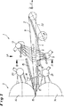
図1には、スタンド間冷却装置として形成された、ストリップ2を冷却するための装置1が図示されている。この装置は、2つのロールスタンドの間に配設されており、図1では、ロールスタンド3の1つだけが図示されている。
FIG. 1 shows a
ストリップ2は、圧延方向又は移送方向Fに、それ自身公知にように、移行テーブル4(移行要素)を介して案内される。熱間圧延されたストリップ2を冷却するため、上のスプレーバー13と下のスプレーバー5が移行テーブル4の上もしくは下に存在する。上のスプレーバー13は、ストリップの上面にスプレーをし、相応に、下のスプレーバー5が、ストリップ2の下面にスプレーをする。スプレーバー5及び13は、冷媒7(水)を塗布するそれぞれ多数のスプレーノズル10を備える。
The
それ自身公知の種々の別の構成要素が設けられている。 Various other components known per se are provided.
ロール14は、ストリップ2が通るロール間隙15を構成する。ロール14の後にスクレーパ16,17が存在する。これらガイド16,17の開口を通って、上もしくは下のスプレーバー18及び19からの噴水が、ストリップ表面にスプレーされる。
The
ロール14の冷却のため、ワークロール冷却装置20もしくは21が設けられている。
A work
移行テーブル4の後にルーパ22が存在する。
A
下のスプレーバー5の噴水は、移行テーブル4の開口6を通ってストリップ2にスプレーされる。この場合、ストリップ2の移送方向Fに対して横方向Qに相並んで配設された少なくとも2つの開口6が移行テーブル4に設けられており、これら開口が、移行テーブル4を上から見て、縦長の形状を備え、開口6の長手方向軸9が、ストリップの移送方向Fに対して角度αを有するように位置調整されていることが重要である。この実施例では、角度は、約30°である。
The fountain of the
この形成は、図2に詳細に図示されている。それぞれ縦長の形状を備える、相並んで配設された複数の開口6を認めることができる。開口6の長手方向軸は、9で指示されており、移行テーブル4の表面の面もしくはストリップ2の面に対して平行に延在する。
This formation is illustrated in detail in FIG. A plurality of
開口6の長さLは、幅Bよりも明らかに大きく、長さLは、幅Bの少なくとも2倍であり、少なくとも3倍が好ましい。更に、個々の開口6が、移送方向Fに対して横方向Qにオーバーラップしていることが見られる。オーバーラップ量bは、隣接する2つの開口6に対して記入されている。これは、相並んで配設された、それぞれ前端もしくは後端11,12を備える2つの開口6’,6”によっても認められる。開口6’の前端11で、開口の端部を方向Qに投影した場合、この開口の端部が、隣接する開口6”の横方向の広がりの後端領域12の後に既に位置することが分かる。これは、冷媒によるストリップ2へのスプレー作用の完全な横方向のオーバーラップの達成を意味する。
The length L of the
更に、図2には、開口6の長手方向軸9に沿って複数のスプレーノズル10が相前後して配設され、これにより、開口の長手方向の広がりに沿って冷媒の連続的な流れが保証されることが示されている。
Further, in FIG. 2, a plurality of
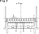
図3には、下のスプレーバー5(上のスプレーバー13に対しても同様のことが当て嵌まる)が、ストリップ2に冷媒をスプレーする多数のスプレーノズル10を備えることが認められる。
3 that the lower spray bar 5 (the same applies to the upper spray bar 13) is provided with a number of
前記開口、即ち冷却水の貫通スリット、の配設もしくは位置調整により、ガイドテーブルの十分な安定性が保証される。即ち、ガイドテーブル4の本質的な機械的な弱体化は、何ら行なわれない。従って、ノズル10のスプレーバー5への相応の配設と関連して、典型的な全ての運転条件下で最適なスプレーパターンが達成可能である。
By providing or adjusting the position of the opening, that is, the through slit for cooling water, sufficient stability of the guide table is ensured. That is, no essential mechanical weakening of the guide table 4 is performed. Thus, an optimal spray pattern can be achieved under all typical operating conditions in connection with the corresponding arrangement of the
1 冷却をするための装置
2 ストリップ
3 ロールスタンド
4 移行要素(移行テーブル)
5 スプレー要素(スプレーバー)
6 開口
6’ 開口
6” 開口
7 冷媒
8 下面
9 長手方向軸
10 スプレーノズル
11 開口の前端
12 開口の後端
13 スプレーバー
14 ロール
15 ロール間隙
16 出口ガイド
17 出口ガイド
18 スプレーバー
19 スプレーバー
20 ワークロール冷却装置
21 ワークロール冷却装置
22 ルーパ
F ストリップの移送方向
Q 水平方向及びストリップの移送方向に対して横方向
α 角度
L 開口の長さ
B 開口の幅
b オーバーラップ量
DESCRIPTION OF
5 Spray elements (spray bar)
6 opening 6 '
Claims (9)
ストリップ(2)の移送方向(F)に対して横方向(Q)に相並んで配設された多数の開口(6)が、移行要素(4)に設けられており、これら開口が、縦長の形状を備え、開口(6)の長手方向軸(9)が、ストリップの移送方向(F)に対して角度(α)を有するように位置調整されており、全ての開口(6)が、移送方向(F)に対して横方向(Q)に平行に相並んで位置するように、移送方向(F)の同じ延在領域にわたって延在し、移行要素(4)の全ての開口(6)が、開口(6)の幅(B)の少なくとも2倍に相当する長さ(L)を備えることを特徴とする装置。The strip (2) is guided through a flatly formed transition element (4) and a spray element (5) is arranged under the transition element (4), the spray element being at least one transition A device (1) for cooling the strip (2) between two roll stands (3) which guides the refrigerant (7) through the opening (6) of the element (4) to the lower surface (8) of the strip (2) In
A number of openings (6) arranged side by side in the transverse direction (Q) relative to the transport direction (F) of the strip (2) are provided in the transition element (4), these openings being elongated And the longitudinal axis (9) of the openings (6) is aligned to have an angle (α) with respect to the transport direction (F) of the strip, and all the openings (6) so as to be positioned side by side parallel to the phase in the transverse direction (Q) with respect to the transport direction (F), and extending over the same extended region of the conveying direction (F), all openings of the transition element (4) (6 ) Comprising a length (L) corresponding to at least twice the width (B) of the opening (6) .
Applications Claiming Priority (5)
| Application Number | Priority Date | Filing Date | Title |
|---|---|---|---|
| DE102007003826 | 2007-01-25 | ||
| DE102007003826.9 | 2007-01-25 | ||
| DE102007010375.3 | 2007-03-03 | ||
| DE102007010375A DE102007010375A1 (en) | 2007-01-25 | 2007-03-03 | Device for cooling a metal strip |
| PCT/EP2007/011050 WO2008089827A1 (en) | 2007-01-25 | 2007-12-17 | Device for cooling a metal strip |
Publications (2)
| Publication Number | Publication Date |
|---|---|
| JP2010516473A JP2010516473A (en) | 2010-05-20 |
| JP5111521B2 true JP5111521B2 (en) | 2013-01-09 |
Family
ID=39106116
Family Applications (1)
| Application Number | Title | Priority Date | Filing Date |
|---|---|---|---|
| JP2009546659A Expired - Fee Related JP5111521B2 (en) | 2007-01-25 | 2007-12-17 | Equipment for cooling the strip |
Country Status (9)
| Country | Link |
|---|---|
| US (1) | US8434338B2 (en) |
| EP (1) | EP2114585A1 (en) |
| JP (1) | JP5111521B2 (en) |
| KR (1) | KR101109462B1 (en) |
| BR (1) | BRPI0720955A2 (en) |
| CA (1) | CA2675790C (en) |
| DE (1) | DE102007010375A1 (en) |
| RU (1) | RU2417130C1 (en) |
| WO (1) | WO2008089827A1 (en) |
Families Citing this family (8)
| Publication number | Priority date | Publication date | Assignee | Title |
|---|---|---|---|---|
| FI20070622L (en) * | 2007-08-17 | 2009-04-15 | Outokumpu Oy | Method and device for checking evenness during cooling of a strip made of stainless steel |
| JP5328726B2 (en) | 2009-08-25 | 2013-10-30 | 三星ディスプレイ株式會社 | Thin film deposition apparatus and organic light emitting display device manufacturing method using the same |
| JP5646261B2 (en) * | 2010-09-22 | 2014-12-24 | 三菱日立製鉄機械株式会社 | Hot strip strip cooling system |
| WO2018055918A1 (en) | 2016-09-23 | 2018-03-29 | 新日鐵住金株式会社 | Device and method for cooling hot-rolled steel sheet |
| WO2019123295A1 (en) * | 2017-12-20 | 2019-06-27 | Danieli & C. Officine Meccaniche S.P.A. | Apparatus for the thermal treatment of metallic products |
| US20230219125A1 (en) | 2020-06-04 | 2023-07-13 | Constellium Neuf-Brisach | Method and equipment for cooling on a reversing hot rolling mill |
| FR3112297B1 (en) | 2020-07-07 | 2024-02-09 | Constellium Neuf Brisach | Cooling process and equipment on a hot reversible rolling mill |
| CN116967394A (en) * | 2023-06-27 | 2023-10-31 | 浙江万里扬新能源驱动有限公司杭州分公司 | Spray mechanism of roll forging machine |
Family Cites Families (15)
| Publication number | Priority date | Publication date | Assignee | Title |
|---|---|---|---|---|
| US3533261A (en) * | 1967-06-15 | 1970-10-13 | Frans Hollander | Method and a device for cooling hot-rolled metal strip on a run-out table after being rolled |
| US4400961A (en) * | 1981-07-15 | 1983-08-30 | Schaming Edward J | Apparatus for removing liquid coolant from metal strips in a rolling mill |
| US4467629A (en) * | 1981-10-02 | 1984-08-28 | Sms Schloemann-Siemag Ag | Method of flattening steel strip in rolling mill |
| JPS59137111A (en) * | 1983-01-28 | 1984-08-07 | Nippon Steel Corp | Hot steel plate cooling device |
| DE3704599A1 (en) | 1987-02-13 | 1988-08-25 | Schloemann Siemag Ag | Method and apparatus for cooling rolled strip |
| JP2892492B2 (en) * | 1990-11-30 | 1999-05-17 | 川崎製鉄株式会社 | Lower cooling device for hot rolled steel sheet |
| ATE211031T1 (en) * | 1995-11-20 | 2002-01-15 | Sms Demag Ag | DEVICE FOR INFLUENCING THE PROFILE OF ROLLED STRIP |
| DE19850739A1 (en) | 1998-11-04 | 2000-05-11 | Schloemann Siemag Ag | Method and device for cooling hot rolled material, in particular hot wide strip |
| JP3642031B2 (en) | 2001-02-15 | 2005-04-27 | Jfeスチール株式会社 | Hot strip strip cooling system |
| DE10131369A1 (en) | 2001-06-28 | 2003-01-09 | Sms Demag Ag | Method and device for cooling and lubricating rolls of a roll stand |
| WO2004014577A1 (en) * | 2002-08-08 | 2004-02-19 | Jfe Steel Corporation | Cooling device, manufacturing method, and manufacturing line for hot rolled steel band |
| JP3770216B2 (en) | 2002-08-08 | 2006-04-26 | Jfeスチール株式会社 | Hot-rolled steel strip cooling device, hot-rolled steel strip manufacturing method, and hot-rolled steel strip manufacturing line |
| DE102004025058A1 (en) | 2004-05-18 | 2005-12-08 | Sms Demag Ag | Method and device for cooling and / or lubrication of rolls and / or rolling stock |
| JP4029871B2 (en) | 2004-07-22 | 2008-01-09 | 住友金属工業株式会社 | Steel plate cooling device, hot-rolled steel plate manufacturing apparatus and manufacturing method |
| AT414102B (en) | 2004-08-04 | 2006-09-15 | Ebner Ind Ofenbau | DEVICE FOR COOLING A TAPE BELT |
-
2007
- 2007-03-03 DE DE102007010375A patent/DE102007010375A1/en not_active Withdrawn
- 2007-12-17 RU RU2009131935/02A patent/RU2417130C1/en not_active IP Right Cessation
- 2007-12-17 CA CA2675790A patent/CA2675790C/en not_active Expired - Fee Related
- 2007-12-17 JP JP2009546659A patent/JP5111521B2/en not_active Expired - Fee Related
- 2007-12-17 US US12/449,138 patent/US8434338B2/en not_active Expired - Fee Related
- 2007-12-17 KR KR1020097010956A patent/KR101109462B1/en active IP Right Grant
- 2007-12-17 BR BRPI0720955-0A patent/BRPI0720955A2/en not_active IP Right Cessation
- 2007-12-17 EP EP07856787A patent/EP2114585A1/en not_active Ceased
- 2007-12-17 WO PCT/EP2007/011050 patent/WO2008089827A1/en active Application Filing
Also Published As
| Publication number | Publication date |
|---|---|
| DE102007010375A1 (en) | 2008-07-31 |
| KR101109462B1 (en) | 2012-01-31 |
| KR20090078838A (en) | 2009-07-20 |
| RU2417130C1 (en) | 2011-04-27 |
| JP2010516473A (en) | 2010-05-20 |
| WO2008089827A1 (en) | 2008-07-31 |
| US20100024504A1 (en) | 2010-02-04 |
| CA2675790C (en) | 2012-02-07 |
| CA2675790A1 (en) | 2008-07-31 |
| US8434338B2 (en) | 2013-05-07 |
| BRPI0720955A2 (en) | 2014-03-18 |
| EP2114585A1 (en) | 2009-11-11 |
| RU2009131935A (en) | 2011-02-27 |
Similar Documents
| Publication | Publication Date | Title |
|---|---|---|
| JP5111521B2 (en) | Equipment for cooling the strip | |
| JP5646261B2 (en) | Hot strip strip cooling system | |
| EP2882542B1 (en) | Method for cleaning and/or descaling a slab or a preliminary strip by means of a descaling device, and descaling device | |
| KR101578987B1 (en) | Method and apparatus for removing coolant liquid from moving metal strip | |
| CA2452057A1 (en) | Method and equipment for cooling and lubricating rolls of a rolling stand | |
| ES2325539T3 (en) | PROCEDURE AND DEVICE FOR THE REGULATED DISTRIBUTION OF TRACTION EFFORT, ESPECIALLY, IN THE AREAS OF THE EDGES OF COLD ROLLED METAL RIBBONS. | |
| KR101279387B1 (en) | Method and device for cooling a leader or band of a metal strand in a hot-rolling mill | |
| JP2019534792A (en) | Rolling stand roll cooling | |
| KR20180097696A (en) | Apparatus and method for cleaning a body having a surface layer to be removed. | |
| JP5640648B2 (en) | Method and apparatus for cooling bottom surface of hot steel sheet | |
| CN101594945B (en) | For the device of cool metal band | |
| JPH0238283B2 (en) | KOHANREIKYAKUSOCHI | |
| CN206550140U (en) | Device for removing oil on surface for milling train | |
| US11559830B2 (en) | Roll stand having a hybrid cooling device | |
| KR100936405B1 (en) | Lubricating Apparatus for Hot Rolling | |
| WO1995005251A1 (en) | Apparatus for use in rolling mills | |
| EP2409781B1 (en) | Curtain coating apparatus | |
| JP7261885B2 (en) | Cooling device made of metal material | |
| EP1027941A2 (en) | Device for introducing lubricant into the roll gap of a hot rolling mill |
Legal Events
| Date | Code | Title | Description |
|---|---|---|---|
| RD04 | Notification of resignation of power of attorney |
Free format text: JAPANESE INTERMEDIATE CODE: A7424 Effective date: 20100604 |
|
| A977 | Report on retrieval |
Free format text: JAPANESE INTERMEDIATE CODE: A971007 Effective date: 20111212 |
|
| A131 | Notification of reasons for refusal |
Free format text: JAPANESE INTERMEDIATE CODE: A131 Effective date: 20120117 |
|
| A601 | Written request for extension of time |
Free format text: JAPANESE INTERMEDIATE CODE: A601 Effective date: 20120416 |
|
| A602 | Written permission of extension of time |
Free format text: JAPANESE INTERMEDIATE CODE: A602 Effective date: 20120423 |
|
| A521 | Request for written amendment filed |
Free format text: JAPANESE INTERMEDIATE CODE: A523 Effective date: 20120710 |
|
| TRDD | Decision of grant or rejection written | ||
| A01 | Written decision to grant a patent or to grant a registration (utility model) |
Free format text: JAPANESE INTERMEDIATE CODE: A01 Effective date: 20120911 |
|
| A01 | Written decision to grant a patent or to grant a registration (utility model) |
Free format text: JAPANESE INTERMEDIATE CODE: A01 |
|
| A61 | First payment of annual fees (during grant procedure) |
Free format text: JAPANESE INTERMEDIATE CODE: A61 Effective date: 20121009 |
|
| FPAY | Renewal fee payment (event date is renewal date of database) |
Free format text: PAYMENT UNTIL: 20151019 Year of fee payment: 3 |
|
| R150 | Certificate of patent or registration of utility model |
Ref document number: 5111521 Country of ref document: JP Free format text: JAPANESE INTERMEDIATE CODE: R150 Free format text: JAPANESE INTERMEDIATE CODE: R150 |
|
| R250 | Receipt of annual fees |
Free format text: JAPANESE INTERMEDIATE CODE: R250 |
|
| R250 | Receipt of annual fees |
Free format text: JAPANESE INTERMEDIATE CODE: R250 |
|
| R250 | Receipt of annual fees |
Free format text: JAPANESE INTERMEDIATE CODE: R250 |
|
| R250 | Receipt of annual fees |
Free format text: JAPANESE INTERMEDIATE CODE: R250 |
|
| R250 | Receipt of annual fees |
Free format text: JAPANESE INTERMEDIATE CODE: R250 |
|
| R250 | Receipt of annual fees |
Free format text: JAPANESE INTERMEDIATE CODE: R250 |
|
| R250 | Receipt of annual fees |
Free format text: JAPANESE INTERMEDIATE CODE: R250 |
|
| LAPS | Cancellation because of no payment of annual fees |