JP5111047B2 - Ink jet recording head and method of manufacturing ink jet recording head. - Google Patents
Ink jet recording head and method of manufacturing ink jet recording head. Download PDFInfo
- Publication number
- JP5111047B2 JP5111047B2 JP2007266703A JP2007266703A JP5111047B2 JP 5111047 B2 JP5111047 B2 JP 5111047B2 JP 2007266703 A JP2007266703 A JP 2007266703A JP 2007266703 A JP2007266703 A JP 2007266703A JP 5111047 B2 JP5111047 B2 JP 5111047B2
- Authority
- JP
- Japan
- Prior art keywords
- silicon layer
- layer
- recording head
- ink
- jet recording
- Prior art date
- Legal status (The legal status is an assumption and is not a legal conclusion. Google has not performed a legal analysis and makes no representation as to the accuracy of the status listed.)
- Expired - Fee Related
Links
- 238000004519 manufacturing process Methods 0.000 title claims description 20
- 239000000758 substrate Substances 0.000 claims description 57
- XUIMIQQOPSSXEZ-UHFFFAOYSA-N Silicon Chemical compound [Si] XUIMIQQOPSSXEZ-UHFFFAOYSA-N 0.000 claims description 55
- 229910052710 silicon Inorganic materials 0.000 claims description 55
- 239000010703 silicon Substances 0.000 claims description 55
- 239000007788 liquid Substances 0.000 claims description 51
- 238000005530 etching Methods 0.000 claims description 49
- 239000013078 crystal Substances 0.000 claims description 28
- 239000000463 material Substances 0.000 claims description 7
- 229910052782 aluminium Inorganic materials 0.000 claims description 6
- XAGFODPZIPBFFR-UHFFFAOYSA-N aluminium Chemical compound [Al] XAGFODPZIPBFFR-UHFFFAOYSA-N 0.000 claims description 6
- 238000004891 communication Methods 0.000 claims description 5
- 239000010410 layer Substances 0.000 description 193
- 229910021421 monocrystalline silicon Inorganic materials 0.000 description 62
- 238000000034 method Methods 0.000 description 22
- 238000010586 diagram Methods 0.000 description 9
- 229910052581 Si3N4 Inorganic materials 0.000 description 8
- VYPSYNLAJGMNEJ-UHFFFAOYSA-N Silicium dioxide Chemical compound O=[Si]=O VYPSYNLAJGMNEJ-UHFFFAOYSA-N 0.000 description 8
- HQVNEWCFYHHQES-UHFFFAOYSA-N silicon nitride Chemical compound N12[Si]34N5[Si]62N3[Si]51N64 HQVNEWCFYHHQES-UHFFFAOYSA-N 0.000 description 8
- 229910052814 silicon oxide Inorganic materials 0.000 description 8
- 238000010438 heat treatment Methods 0.000 description 7
- 238000007747 plating Methods 0.000 description 6
- 239000011241 protective layer Substances 0.000 description 6
- KRHYYFGTRYWZRS-UHFFFAOYSA-N Fluorane Chemical compound F KRHYYFGTRYWZRS-UHFFFAOYSA-N 0.000 description 4
- PCHJSUWPFVWCPO-UHFFFAOYSA-N gold Chemical compound [Au] PCHJSUWPFVWCPO-UHFFFAOYSA-N 0.000 description 4
- 239000010931 gold Substances 0.000 description 4
- 229910052737 gold Inorganic materials 0.000 description 4
- 229910000040 hydrogen fluoride Inorganic materials 0.000 description 4
- 239000004065 semiconductor Substances 0.000 description 4
- 229910021419 crystalline silicon Inorganic materials 0.000 description 3
- CTQNGGLPUBDAKN-UHFFFAOYSA-N O-Xylene Chemical compound CC1=CC=CC=C1C CTQNGGLPUBDAKN-UHFFFAOYSA-N 0.000 description 2
- 239000011248 coating agent Substances 0.000 description 2
- 238000000576 coating method Methods 0.000 description 2
- 238000004040 coloring Methods 0.000 description 2
- 239000012212 insulator Substances 0.000 description 2
- 238000005192 partition Methods 0.000 description 2
- 239000011347 resin Substances 0.000 description 2
- 229920005989 resin Polymers 0.000 description 2
- 230000008719 thickening Effects 0.000 description 2
- 239000008096 xylene Substances 0.000 description 2
- 239000003513 alkali Substances 0.000 description 1
- PNEYBMLMFCGWSK-UHFFFAOYSA-N aluminium oxide Inorganic materials [O-2].[O-2].[O-2].[Al+3].[Al+3] PNEYBMLMFCGWSK-UHFFFAOYSA-N 0.000 description 1
- 229910021417 amorphous silicon Inorganic materials 0.000 description 1
- 238000009835 boiling Methods 0.000 description 1
- 239000000919 ceramic Substances 0.000 description 1
- 230000015271 coagulation Effects 0.000 description 1
- 238000005345 coagulation Methods 0.000 description 1
- 238000005516 engineering process Methods 0.000 description 1
- 238000000605 extraction Methods 0.000 description 1
- 239000004744 fabric Substances 0.000 description 1
- 239000000835 fiber Substances 0.000 description 1
- 239000011521 glass Substances 0.000 description 1
- 230000017525 heat dissipation Effects 0.000 description 1
- 239000010985 leather Substances 0.000 description 1
- 229910052751 metal Inorganic materials 0.000 description 1
- 239000002184 metal Substances 0.000 description 1
- 238000000206 photolithography Methods 0.000 description 1
- 239000004033 plastic Substances 0.000 description 1
- 229910021426 porous silicon Inorganic materials 0.000 description 1
- HBMJWWWQQXIZIP-UHFFFAOYSA-N silicon carbide Chemical compound [Si+]#[C-] HBMJWWWQQXIZIP-UHFFFAOYSA-N 0.000 description 1
- 229910010271 silicon carbide Inorganic materials 0.000 description 1
- 238000000992 sputter etching Methods 0.000 description 1
- 239000002023 wood Substances 0.000 description 1
Images


Classifications
-
- B—PERFORMING OPERATIONS; TRANSPORTING
- B41—PRINTING; LINING MACHINES; TYPEWRITERS; STAMPS
- B41J—TYPEWRITERS; SELECTIVE PRINTING MECHANISMS, i.e. MECHANISMS PRINTING OTHERWISE THAN FROM A FORME; CORRECTION OF TYPOGRAPHICAL ERRORS
- B41J2/00—Typewriters or selective printing mechanisms characterised by the printing or marking process for which they are designed
- B41J2/005—Typewriters or selective printing mechanisms characterised by the printing or marking process for which they are designed characterised by bringing liquid or particles selectively into contact with a printing material
- B41J2/01—Ink jet
- B41J2/135—Nozzles
- B41J2/14—Structure thereof only for on-demand ink jet heads
- B41J2/14016—Structure of bubble jet print heads
- B41J2/14032—Structure of the pressure chamber
- B41J2/1404—Geometrical characteristics
-
- B—PERFORMING OPERATIONS; TRANSPORTING
- B41—PRINTING; LINING MACHINES; TYPEWRITERS; STAMPS
- B41J—TYPEWRITERS; SELECTIVE PRINTING MECHANISMS, i.e. MECHANISMS PRINTING OTHERWISE THAN FROM A FORME; CORRECTION OF TYPOGRAPHICAL ERRORS
- B41J2/00—Typewriters or selective printing mechanisms characterised by the printing or marking process for which they are designed
- B41J2/005—Typewriters or selective printing mechanisms characterised by the printing or marking process for which they are designed characterised by bringing liquid or particles selectively into contact with a printing material
- B41J2/01—Ink jet
- B41J2/135—Nozzles
- B41J2/14—Structure thereof only for on-demand ink jet heads
- B41J2/14016—Structure of bubble jet print heads
- B41J2/14072—Electrical connections, e.g. details on electrodes, connecting the chip to the outside...
-
- B—PERFORMING OPERATIONS; TRANSPORTING
- B41—PRINTING; LINING MACHINES; TYPEWRITERS; STAMPS
- B41J—TYPEWRITERS; SELECTIVE PRINTING MECHANISMS, i.e. MECHANISMS PRINTING OTHERWISE THAN FROM A FORME; CORRECTION OF TYPOGRAPHICAL ERRORS
- B41J2/00—Typewriters or selective printing mechanisms characterised by the printing or marking process for which they are designed
- B41J2/005—Typewriters or selective printing mechanisms characterised by the printing or marking process for which they are designed characterised by bringing liquid or particles selectively into contact with a printing material
- B41J2/01—Ink jet
- B41J2/135—Nozzles
- B41J2/14—Structure thereof only for on-demand ink jet heads
- B41J2/14016—Structure of bubble jet print heads
- B41J2/14088—Structure of heating means
- B41J2/14112—Resistive element
- B41J2/1412—Shape
-
- B—PERFORMING OPERATIONS; TRANSPORTING
- B41—PRINTING; LINING MACHINES; TYPEWRITERS; STAMPS
- B41J—TYPEWRITERS; SELECTIVE PRINTING MECHANISMS, i.e. MECHANISMS PRINTING OTHERWISE THAN FROM A FORME; CORRECTION OF TYPOGRAPHICAL ERRORS
- B41J2/00—Typewriters or selective printing mechanisms characterised by the printing or marking process for which they are designed
- B41J2/005—Typewriters or selective printing mechanisms characterised by the printing or marking process for which they are designed characterised by bringing liquid or particles selectively into contact with a printing material
- B41J2/01—Ink jet
- B41J2/135—Nozzles
- B41J2/14—Structure thereof only for on-demand ink jet heads
- B41J2/14016—Structure of bubble jet print heads
- B41J2/14088—Structure of heating means
- B41J2/14112—Resistive element
- B41J2/14137—Resistor surrounding the nozzle opening
-
- B—PERFORMING OPERATIONS; TRANSPORTING
- B41—PRINTING; LINING MACHINES; TYPEWRITERS; STAMPS
- B41J—TYPEWRITERS; SELECTIVE PRINTING MECHANISMS, i.e. MECHANISMS PRINTING OTHERWISE THAN FROM A FORME; CORRECTION OF TYPOGRAPHICAL ERRORS
- B41J2/00—Typewriters or selective printing mechanisms characterised by the printing or marking process for which they are designed
- B41J2/005—Typewriters or selective printing mechanisms characterised by the printing or marking process for which they are designed characterised by bringing liquid or particles selectively into contact with a printing material
- B41J2/01—Ink jet
- B41J2/135—Nozzles
- B41J2/16—Production of nozzles
- B41J2/1601—Production of bubble jet print heads
-
- B—PERFORMING OPERATIONS; TRANSPORTING
- B41—PRINTING; LINING MACHINES; TYPEWRITERS; STAMPS
- B41J—TYPEWRITERS; SELECTIVE PRINTING MECHANISMS, i.e. MECHANISMS PRINTING OTHERWISE THAN FROM A FORME; CORRECTION OF TYPOGRAPHICAL ERRORS
- B41J2/00—Typewriters or selective printing mechanisms characterised by the printing or marking process for which they are designed
- B41J2/005—Typewriters or selective printing mechanisms characterised by the printing or marking process for which they are designed characterised by bringing liquid or particles selectively into contact with a printing material
- B41J2/01—Ink jet
- B41J2/135—Nozzles
- B41J2/16—Production of nozzles
- B41J2/1621—Manufacturing processes
- B41J2/1626—Manufacturing processes etching
- B41J2/1628—Manufacturing processes etching dry etching
-
- B—PERFORMING OPERATIONS; TRANSPORTING
- B41—PRINTING; LINING MACHINES; TYPEWRITERS; STAMPS
- B41J—TYPEWRITERS; SELECTIVE PRINTING MECHANISMS, i.e. MECHANISMS PRINTING OTHERWISE THAN FROM A FORME; CORRECTION OF TYPOGRAPHICAL ERRORS
- B41J2/00—Typewriters or selective printing mechanisms characterised by the printing or marking process for which they are designed
- B41J2/005—Typewriters or selective printing mechanisms characterised by the printing or marking process for which they are designed characterised by bringing liquid or particles selectively into contact with a printing material
- B41J2/01—Ink jet
- B41J2/135—Nozzles
- B41J2/16—Production of nozzles
- B41J2/1621—Manufacturing processes
- B41J2/1626—Manufacturing processes etching
- B41J2/1629—Manufacturing processes etching wet etching
-
- B—PERFORMING OPERATIONS; TRANSPORTING
- B41—PRINTING; LINING MACHINES; TYPEWRITERS; STAMPS
- B41J—TYPEWRITERS; SELECTIVE PRINTING MECHANISMS, i.e. MECHANISMS PRINTING OTHERWISE THAN FROM A FORME; CORRECTION OF TYPOGRAPHICAL ERRORS
- B41J2/00—Typewriters or selective printing mechanisms characterised by the printing or marking process for which they are designed
- B41J2/005—Typewriters or selective printing mechanisms characterised by the printing or marking process for which they are designed characterised by bringing liquid or particles selectively into contact with a printing material
- B41J2/01—Ink jet
- B41J2/135—Nozzles
- B41J2/16—Production of nozzles
- B41J2/1621—Manufacturing processes
- B41J2/1632—Manufacturing processes machining
- B41J2/1634—Manufacturing processes machining laser machining
-
- B—PERFORMING OPERATIONS; TRANSPORTING
- B41—PRINTING; LINING MACHINES; TYPEWRITERS; STAMPS
- B41J—TYPEWRITERS; SELECTIVE PRINTING MECHANISMS, i.e. MECHANISMS PRINTING OTHERWISE THAN FROM A FORME; CORRECTION OF TYPOGRAPHICAL ERRORS
- B41J2/00—Typewriters or selective printing mechanisms characterised by the printing or marking process for which they are designed
- B41J2/005—Typewriters or selective printing mechanisms characterised by the printing or marking process for which they are designed characterised by bringing liquid or particles selectively into contact with a printing material
- B41J2/01—Ink jet
- B41J2/135—Nozzles
- B41J2/16—Production of nozzles
- B41J2/1621—Manufacturing processes
- B41J2/1637—Manufacturing processes molding
- B41J2/1639—Manufacturing processes molding sacrificial molding
-
- B—PERFORMING OPERATIONS; TRANSPORTING
- B41—PRINTING; LINING MACHINES; TYPEWRITERS; STAMPS
- B41J—TYPEWRITERS; SELECTIVE PRINTING MECHANISMS, i.e. MECHANISMS PRINTING OTHERWISE THAN FROM A FORME; CORRECTION OF TYPOGRAPHICAL ERRORS
- B41J2/00—Typewriters or selective printing mechanisms characterised by the printing or marking process for which they are designed
- B41J2/005—Typewriters or selective printing mechanisms characterised by the printing or marking process for which they are designed characterised by bringing liquid or particles selectively into contact with a printing material
- B41J2/01—Ink jet
- B41J2/135—Nozzles
- B41J2/16—Production of nozzles
- B41J2/1621—Manufacturing processes
- B41J2/164—Manufacturing processes thin film formation
- B41J2/1643—Manufacturing processes thin film formation thin film formation by plating
-
- B—PERFORMING OPERATIONS; TRANSPORTING
- B41—PRINTING; LINING MACHINES; TYPEWRITERS; STAMPS
- B41J—TYPEWRITERS; SELECTIVE PRINTING MECHANISMS, i.e. MECHANISMS PRINTING OTHERWISE THAN FROM A FORME; CORRECTION OF TYPOGRAPHICAL ERRORS
- B41J2/00—Typewriters or selective printing mechanisms characterised by the printing or marking process for which they are designed
- B41J2/005—Typewriters or selective printing mechanisms characterised by the printing or marking process for which they are designed characterised by bringing liquid or particles selectively into contact with a printing material
- B41J2/01—Ink jet
- B41J2/135—Nozzles
- B41J2/14—Structure thereof only for on-demand ink jet heads
- B41J2002/1437—Back shooter
-
- Y—GENERAL TAGGING OF NEW TECHNOLOGICAL DEVELOPMENTS; GENERAL TAGGING OF CROSS-SECTIONAL TECHNOLOGIES SPANNING OVER SEVERAL SECTIONS OF THE IPC; TECHNICAL SUBJECTS COVERED BY FORMER USPC CROSS-REFERENCE ART COLLECTIONS [XRACs] AND DIGESTS
- Y10—TECHNICAL SUBJECTS COVERED BY FORMER USPC
- Y10T—TECHNICAL SUBJECTS COVERED BY FORMER US CLASSIFICATION
- Y10T29/00—Metal working
- Y10T29/49—Method of mechanical manufacture
- Y10T29/49401—Fluid pattern dispersing device making, e.g., ink jet
Description
本発明は、インクジェット記録ヘッド、およびインクジェット記録ヘッドの製造方法に関する。 The present invention relates to an ink jet recording head and a method for manufacturing the ink jet recording head.
インクジェット記録方式(液体噴射記録方式)で用いられるインクジェット記録ヘッドは、一般にオリフィスプレートに形成された微細な吐出口、液流路、および液流路の一部に設けられる液体吐出圧力発生部を複数具えている。またこれら液流路に連通し、ヘッドの基板に貫通孔として形成される供給口を具えていることが多い。 An ink jet recording head used in an ink jet recording method (liquid jet recording method) generally includes a plurality of fine discharge ports formed in an orifice plate, a liquid flow path, and a plurality of liquid discharge pressure generating portions provided in a part of the liquid flow path. It has. Further, in many cases, a supply port formed as a through hole is provided in the head substrate in communication with these liquid flow paths.
このようなインクジェット記録ヘッドは、吐出口に連通する流路それぞれに、発熱部(ヒータ)が設けられ、これらが記録素子を構成している。そして、そのヒータの発熱抵抗体に記録信号に応じた電気エネルギを選択的に印加することによって生じるエネルギを利用して、熱作用面上にインクを急激に加熱し、膜沸騰を生じさせ、その際に発生する気泡の圧力により吐出口からインクを吐出させる。 In such an ink jet recording head, a heat generating portion (heater) is provided in each flow path communicating with the ejection port, and these constitute a recording element. Then, using the energy generated by selectively applying the electrical energy corresponding to the recording signal to the heating resistor of the heater, the ink is rapidly heated on the heat acting surface to cause film boiling, Ink is ejected from the ejection port by the pressure of bubbles generated at the time.
上述したようなヒータを用いた記録ヘッドとして、例えば特許文献1には、オリフィスプレートの液流路面側に液体吐出圧力発生部を具えた、所謂バックシュータ型(以降でもこの呼称を用いる)のインクジェット記録ヘッドが開示されている。バックシュータ型の記録ヘッドは、オリフィスプレートもしくはその一部と、基板面に液体吐出圧力発生部およびその駆動回路を、汎用の半導体製造方法により連続して形成することが可能である。 As a recording head using a heater as described above, for example, Japanese Patent Application Laid-Open No. H10-228707 discloses a so-called back shooter type (hereinafter referred to as this name) ink jet having a liquid discharge pressure generating portion on the liquid flow path surface side of an orifice plate. A recording head is disclosed. The back shooter type recording head can continuously form an orifice plate or a part thereof, a liquid discharge pressure generating portion and a driving circuit thereof on a substrate surface by a general-purpose semiconductor manufacturing method.
上記のバックシュータ型の記録ヘッドの基板は、例えば、Silicon on Insulator(SOI)技術により作製される。SOI技術による絶縁物上の単結晶シリコン半導体層が形成された基板は、通常のシリコン集積回路を作製するバルクシリコン基板と比べて数々の優位点を有する。そのようなSOI基板を用いてバックシュータ型の記録ヘッドが特許文献2に開示されている。 The substrate of the back shooter type recording head is manufactured by, for example, the Silicon on Insulator (SOI) technique. A substrate on which a single crystal silicon semiconductor layer on an insulator by SOI technology is formed has many advantages over a bulk silicon substrate for manufacturing a normal silicon integrated circuit. A back shooter type recording head using such an SOI substrate is disclosed in Patent Document 2.
特許文献2に開示のバックシュータ型記録ヘッドの製造方法は、以下のようなものである。
B1.中に誘電体層903を有するSOI基板901を用意する工程
B2.前記基板の前記誘電体層903より表側の面に液流路の壁を形成する位置に合わせて、前記誘電体層まで達する溝を設ける工程
B3.前記基板の表面および前記溝の表面に第一のエッチングストップ層920を形成する工程(図8(a))
B4.前記基板表面の第一のエッチングストップ層920上にエネルギ発生素子906およびその駆動回路を形成する工程
B5.前記SOI基板内の前記誘電体層903より裏側の面から誘電体層903まで到達する供給口908を形成する工程
B6.前記供給口908の内面に第二のエッチングストップ層921を形成する工程
B7.前記のエッチングストップ層921の前記誘電体層903と接触している部分を選択的に除去する工程(図8(b))
B8.前記誘電体層903の前記供給口908内に露出した部分を除去する工程
B9.前記供給口908を介して、前記基板の前記誘電体層903と、前記第一のエッチングストップ層920とで囲まれる部分を等方的なエッチング手法により除去し、液流路909を形成する工程
B10.前記第一のエッチングストップ層920をエッチングし、吐出口910を形成する工程(図8(c))
The manufacturing method of the back shooter type recording head disclosed in Patent Document 2 is as follows.
B1. Step of preparing
B2. A step of providing a groove reaching the dielectric layer in accordance with a position where a wall of the liquid flow path is formed on the surface of the substrate on the front side of the
B3. A step of forming a first
B4. Forming an energy generating
B5. Forming a
B6. Forming a second
B7. A step of selectively removing a portion of the
B8. Removing a portion of the
B9. A step of forming a
B10. Step of etching the first
これらのB1からB10までの工程によって作製されたインクジェット記録ヘッドは、第1のエッチングストップ層920と誘電体層903に囲まれた部分をエッチング手法により除去され、流路909が形成される。
In the ink jet recording head manufactured by the processes from B1 to B10, a portion surrounded by the first
また、上記の製造方法により作製されたインクジェット記録ヘッドでは、液流路の壁になる部分に第一のエッチングストップ層920を形成しなければならず、一般的にフォトリソ工程とRIEによるエッチング工程と、その内壁への成膜工程が必要であり、工程が煩雑になる。
In addition, in the ink jet recording head manufactured by the above manufacturing method, the first
さらに、工程B4においてエネルギ発生素子とその駆動回路の形成を行うため、溝は第一のエッチングストップ層920に埋められなければならず、これらの幅を、例えば2μm程度になる様に十分に狭くしなければならない。
Further, in order to form the energy generating element and its drive circuit in step B4, the groove must be filled in the first
一方、液流路の基板面に垂直な方向の寸法、すなわち、液流路の深さは一般的には10μm以上がこのましいため、アスペクト比が5以上という高い溝を形成る必要がある。この場合、溝形成にかかる時間が大きく、生産性がよいとはいえない。 On the other hand, since the dimension of the liquid flow path in the direction perpendicular to the substrate surface, that is, the depth of the liquid flow path is generally 10 μm or more, it is necessary to form a high groove with an aspect ratio of 5 or more. In this case, it takes a long time to form the groove, and it cannot be said that productivity is good.
本発明は以上の点を鑑みてなされたものであり、所期の目的に沿った液流路の形状を、有したインクジェット記録ヘッド、およびそのインクジェット記録ヘッドを工程的な負荷を少なくし、簡便に製造する方法を提供することを目的とする。 The present invention has been made in view of the above points, and has an ink jet recording head having the shape of a liquid flow path in accordance with an intended purpose, and the ink jet recording head has a reduced process load and is simple. It aims at providing the method of manufacturing to.
上記目的を達成するために本発明は、インクの吐出口と、前記吐出口からインクを吐出するために利用されるエネルギを発生するエネルギ発生素子と、該吐出口へと連通するインクの流路と、前記流路と連通しインクを供給するためのインク供給口と、を具えたインクジェット記録ヘッドの製造方法において、第一のシリコン層と、第二のシリコン層と、前記第一のシリコン層と前記第二のシリコン層の間に設けられた誘電体層と、を有するSOI基板を用意する工程と、前記第一のシリコン層の上に、シリコンよりもエッチングされやすい材料により犠牲層を設ける工程と、前記犠牲層を覆うようにエッチングストップ層を形成する工程と、前記エッチングストップ層の上に、前記エネルギ発生素子を形成する工程と、前記第二のシリコン層の一部と前記誘電体層の一部とを除去して、前記インク供給口を形成する工程と、前記第一のシリコン層に対して、エッチングを行い、被エッチング領域を前記犠牲層に到達させ、前記犠牲層を除去して前記流路を形成する工程と、前記エッチングストップ層の一部を除去して前記吐出口を形成する工程と、を有することを特徴とする。 To achieve the above object, the present invention relates to an ink ejection port, an energy generating element that generates energy used to eject ink from the ejection port, and an ink flow path communicating with the ejection port. A first silicon layer, a second silicon layer, and the first silicon layer. And a dielectric layer provided between the second silicon layer, and a sacrificial layer provided on the first silicon layer with a material that is more easily etched than silicon. a step, a step of forming an etch stop layer so as to cover the sacrificial layer, on the etching stop layer, a step of forming said energy generating element, wherein the second silicon And removing the part of the dielectric layer and part of the dielectric layer to form the ink supply port, etching the first silicon layer, and reaching the etched region to the sacrificial layer And the step of removing the sacrificial layer to form the flow path and the step of removing a part of the etching stop layer to form the discharge port.
以上の構成によれば、誘電体層に沿って液流路を形成することができる。その結果、供給口と液流路との連通部を精度よく形成でき、かつ安定した基板を提供することができる。また、所期の目的に沿った液流路の形状を有したインクジェット記録ヘッドを得ることができる。 According to the above configuration, the liquid flow path can be formed along the dielectric layer. As a result, a communication portion between the supply port and the liquid channel can be formed with high accuracy, and a stable substrate can be provided. In addition, an ink jet recording head having a liquid flow path shape that meets the intended purpose can be obtained.
以下に図面を参照して本発明における実施形態を詳細に説明する。
(第1の実施形態)
図1は、本実施形態に係るインクジェット記録ヘッドの一部を破断して示した斜視図である。インクジェット記録ヘッド1のシリコン基板6の上には、複数の吐出口2と、液路3と、ヒータ4と、インク供給口5が設けられている。インクは、インク供給口5から各液路3に供給され、液路3に設けられたエネルギ発生素子としてのヒータ4の熱エネルギにより、インクは吐出口2から吐出される。エネルギ発生素子4は、ヒータに限られず、圧電素子等を用いることもできる。本形態の場合、吐出口2は、エネルギ発生素子4により、囲まれる、或いは挟まれる部分に設けられるが、これに限定されることはない。吐出口がエネルギ発生素子4の一方の側に隣接する形で存在してもよい。
Embodiments of the present invention will be described below in detail with reference to the drawings.
(First embodiment)
FIG. 1 is a perspective view in which a part of the ink jet recording head according to the present embodiment is cut away. A plurality of ejection ports 2, a liquid path 3, a heater 4, and an
なお、インクジェット記録ヘッドは、プリンタ、複写機、通信システムを有するファクシミリ、プリンタ部を有するワードプロセッサなどの装置、さらには各種処理装置と複合的に組み合わせた産業記録装置に搭載可能である。そして、この液体吐出ヘッドを用いることによって、紙、糸、繊維、布帛、皮革、金属、プラスチック、ガラス、木材、セラミックスなど種々の記録媒体に記録を行うことができる。なお、本明細書内で用いられる「記録」とは、文字や図形などの意味を持つ画像を記録媒体に対して付与することだけでなく、パターンなどの意味を持たない画像を付与することも意味することとする。 The ink jet recording head can be mounted on an apparatus such as a printer, a copying machine, a facsimile having a communication system, a word processor having a printer unit, or an industrial recording apparatus combined with various processing apparatuses. By using this liquid discharge head, recording can be performed on various recording media such as paper, thread, fiber, fabric, leather, metal, plastic, glass, wood, and ceramics. Note that “recording” used in the present specification not only applies an image having a meaning such as a character or a figure to a recording medium but also an image having no meaning such as a pattern. I mean.
さらに、「インク」または「液体」とは、広く解釈されるべきものであり、記録媒体上に付与されることによって、画像、模様、パターン等の形成、記録媒体の加工、或いはインクまたは記録媒体の処理に供される液体を言うものとする。ここで、インクまたは記録媒体の処理としては、例えば、記録媒体に付与されるインク中の色材の凝固または不溶化による定着性の向上や、記録品位ないし発色性の向上、画像耐久性の向上などのことを言う。 Furthermore, “ink” or “liquid” is to be interpreted widely, and is applied on a recording medium to form an image, a pattern, a pattern, or the like, process the recording medium, or ink or recording medium. It shall mean the liquid that is subjected to the treatment. Here, as the treatment of the ink or the recording medium, for example, the fixing property is improved by coagulation or insolubilization of the coloring material in the ink applied to the recording medium, the recording quality or coloring property is improved, and the image durability is improved Say that.
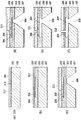
図2(a)〜(f)は、本発明の第1の実施形態に係るインクジェット記録ヘッドの製造方法を示す模式的断面図であり、図1におけるIIF−IIFに沿った断面図である。 2A to 2F are schematic cross-sectional views illustrating the method for manufacturing the ink jet recording head according to the first embodiment of the present invention, and are cross-sectional views along IIF-IIF in FIG.
まず、第一の単結晶シリコン層(第一のシリコン層)201と、誘電体層203と、第二の単結晶シリコン層(第二のシリコン層)202とを有する直径150mmのSOI基板215を用意する。本実施形態では、第一の単結晶シリコン層201は、主表面213が{100}面である単結晶シリコン層であり、厚さは25μmである。また、誘電体層203は、酸化シリコン層であり、厚さは0.3μmである。さらに、第二の単結晶シリコン層202は、主表面214が{100}面である単結晶シリコン層であり、厚さは600μmである。
First, an
図2(a)は、主表面213が{100}面である単結晶シリコンからなる第一の単結晶シリコン層201と、誘電体層203と、主表面214が{100}面である単結晶シリコンからなる第二の単結晶シリコン層202により作製されたSOI基板215を示す図である。
FIG. 2A shows a first single
次に、第一の単結晶シリコン層201が存在する面(以下、表面ともいう。)上に、犠牲層204となるアルミ層を液流路の形状に合わせてパターニングする。この犠牲層204には、犠牲層の角の部分に補償パターンを設けることにより、後述するエッチングが適切に行なわれるようにすることもできる。すなわち、液流路形成部と、供給口形成部の連結部分に、補償パターンを設けることにより、例えば、各々の液流路を仕切る壁であるリブの先端が形成される部分で、犠牲層をくびれた様な平面形状にすることができる。
Next, an aluminum layer to be the
なお、本実施形態では、犠牲層204には、アルカリに可溶なアルミニウムを用いたが、ポーラスシリコン、他の結晶シリコン、アモルファスシリコン等であってもよい。これらの場合、後述するSOI基板の犠牲層が設けられた裏面側から犠牲層204までエッチングを行う工程、犠牲層204を除去し液流路を形成する工程を、一回の結晶異方性エッチングにより行うことができる。
In this embodiment, the
また、犠牲層204は、酸化シリコン等のフッ化水素により除去が可能な材料(フッ化水素に溶解可能な材料)を用い、誘電体層203は、窒化シリコン、炭化シリコン、アルミナ等の無機層を用い、フッ化水素により除去され難い材料を用いてもよい。この場合、後述する犠牲層204を除去する工程は、フッ化水素を用いることができる。
The
次に、犠牲層204の上に、絶縁層を兼ねたエッチングストップ層205である窒化シリコン層を成膜する(被覆する)。酸化シリコンを用いることもできる。そしてさらに、汎用の半導体工程により、通電に応じて前記吐出口からインクを吐出するために利用されるエネルギを発生するエネルギ発生素子である発熱抵抗体206とその駆動回路を形成する。この駆動回路は、回路上にメッキ等のコーティング技術により膜を追加し、オリフィスプレートを厚化してもよい。オリフィスプレートを厚化することにより、吐出口を長くすることができ、吐出させるインクの直進性を増すことができる。
Next, a silicon nitride layer that is an
最上面には窒化シリコンにより発熱抵抗体206の保護層212を形成する。また、第二の単結晶シリコン層202が存在する面(以下、裏面ともいう。)には、酸化シリコン層207を形成する。
A
図2(b)は、裏面マスク層207、第二の単結晶シリコン層202、誘電体層203、犠牲層204、エッチングストップ層205、発熱抵抗体206、保護層212を積層した基板を示す。
FIG. 2B shows a substrate on which a
なお、この後に、追加層として保護層212上にさらに、放熱部材としてメッキにより金を成長させてもよい。このとき、吐出口形成位置には予めドライフィルムをパターニングして設け、メッキ成長後にこれを除去することにより金が存在しないようにすることもできる。
After this, gold may be grown on the
次に、環化ゴム樹脂を基板表面側に塗布し、一時的な保護層211とする。裏面に存在する酸化シリコン層の供給口を形成する領域をエッチングして除去した後、第二の単結晶シリコン層202に対して誘電体層203まで、結晶異方性エッチングを行う。これにより第二のシリコン層202の一部と誘電体層203の一部とを除去して、供給口208を形成する。
Next, a cyclized rubber resin is applied to the substrate surface side to form a temporary
図2(c)は、誘電体層203まで供給口208が形成された基板を示す図である。
FIG. 2C is a diagram showing a substrate in which the
次に、供給口208を介して誘電体層203を除去した後、第一の単結晶シリコン層201に対し、結晶異方性エッチングを行い、被エッチング領域を犠牲層204であるアルミ層まで到達させる。
Next, after removing the
図2(d)は、犠牲層204までエッチングを行った基板を示す図である。
FIG. 2D is a diagram showing a substrate that has been etched up to the
エッチングを継続して犠牲層204を除去しつつ、犠牲層204のパターンに沿って液流路を形成する。
The liquid flow path is formed along the pattern of the
図2(e)は、犠牲層204のパターンに沿い、底面が誘電体層203で形成された、液流路209が設けられた基板を示す図である。このとき、液流路の底面は誘電体層203で形成され、また側面は(111)結晶面で形成されることになる。
FIG. 2E is a diagram showing a substrate provided with a
最後に、環化ゴムをキシレンにて除去した後、RIEによりエッチングストップ層205である窒化シリコン層をエッチングし、吐出口210を形成する。
Finally, after removing the cyclized rubber with xylene, the silicon nitride layer as the
図2(f)は、吐出口210が形成された基板を示す図である。
FIG. 2F is a diagram illustrating the substrate on which the
(第2の実施形態)
図3は、本発明の第2の実施形態に係るインクジェット記録ヘッドの製造方法を示す模式的断面図である。断面は図2のものと同様である。本実施形態は、SOI基板の二つの単結晶シリコン層の結晶方位を互いにことならせた例である。
(Second Embodiment)
FIG. 3 is a schematic cross-sectional view showing a method for manufacturing an ink jet recording head according to the second embodiment of the present invention. The cross section is similar to that of FIG. This embodiment is an example in which the crystal orientations of two single crystal silicon layers of an SOI substrate are different from each other.
まず、第一の単結晶シリコン層(第一のシリコン層)と、誘電体層と、第二の単結晶シリコン層(第二のシリコン層)とを張り合わせて作製された直径150mmのSOI基板314を用意する。本実施形態では、第一の単結晶シリコン層301は、主表面312が{100}面である単結晶シリコン層であり、厚さは25μmである。また、誘電体層303は、酸化シリコン層であり、厚さは0.3μmである。さらに、第二の単結晶シリコン層302は、主表面313が{110}面である単結晶シリコン層であり、厚さは600μmである。
First, an
図3(a)は、主表面312が{100}面である単結晶シリコンからなる第一の単結晶シリコン層301と、誘電体層303と、主表面313が{110}面である単結晶シリコンからなる第二の単結晶シリコン層302により作製されたSOI基板を示す図である。
FIG. 3A shows a first single
次に、第一の単結晶シリコン層301が存在する面(以下、表面ともいう。)上に、犠牲層304となるアルミ層を液流路の形状に合わせてパターニングする。この犠牲層304には、犠牲層の角の部分に補償パターンを設けることにより、後述するエッチングが適切に行なわれるようにすることもできる。すなわち、液流路形成部と、供給口形成部の連結部分に、補償パターンを設けることにより、例えば、各々の液流路を仕切る壁であるリブの先端が形成される部分で、犠牲層をくびれた様な平面形状にすることができる。
Next, an aluminum layer to be the
犠牲層204の材料については第1の実施形態と同様である。
The material of the
次に、犠牲層304の上に、エッチングストップ層305と絶縁層を兼ねた窒化シリコン層を成膜する(被覆する)。そしてさらに、汎用の半導体工程により、吐出圧力発生素子である発熱抵抗体306とその駆動回路を形成する。この駆動回路は、回路上にメッキ等のコーティング技術により膜を追加し、オリフィスプレートを厚化してもよい。オリフィスプレートを厚化することにより、吐出口を長くすることができ、吐出させるインクの直進性を増すことができる。
Next, a silicon nitride layer serving as an
最上面には窒化シリコン層を形成する。また、第二の単結晶シリコン層302が存在する面(以下、裏面ともいう。)には、酸化シリコン層307を形成する。
A silicon nitride layer is formed on the uppermost surface. In addition, a
なお、駆動回路は、第一の単結晶シリコン層301にMOSトランジスタを設けることもできる。
Note that the driver circuit can include a MOS transistor in the first single
図3(b)は、裏面マスク層307、第二の単結晶シリコン層304、誘電体層303、犠牲層304、エッチングストップ層305、発熱抵抗体306、窒化シリコン層312を積層した基板を示す。
FIG. 3B shows a substrate on which a
なお、この後に、追加層としてメッキにより金を成長させてもよい。このとき、吐出口形成位置には予めドライフィルムをパターニングして設け、メッキ成長後にこれを除去することにより金が存在しないようにすることもできる。 After this, gold may be grown by plating as an additional layer. At this time, a dry film may be patterned in advance at the discharge port forming position and removed after the plating growth so that gold does not exist.
次に、環化ゴム樹脂を基板表面側に塗布し、一時的な保護層とする(不図示)。裏面に存在する酸化シリコン層の供給口を形成する領域をエッチングして除去した後、パターンの角部分にレーザーにより誘電体層近くまでの深さの先導孔311を形成する。この先導孔は、後述する結晶異方性エッチングを行うとき、異方性エッチング液の流路となる孔である。この先導孔によりエッチングレートが早くなるとともに、先導孔の内面からエッチングが開始されるため、この先導孔によってエッチング開始面を決定することができる。そして、第二の単結晶シリコン層302に対して誘電体層303まで、結晶異方性エッチングを行い、供給口を形成する。
Next, a cyclized rubber resin is applied to the substrate surface side to form a temporary protective layer (not shown). After the region for forming the supply port of the silicon oxide layer on the back surface is removed by etching, a leading
図3(c)は、供給口308が形成された基板を示す図である。
FIG. 3C is a diagram illustrating the substrate on which the
次に、供給口308を介して誘電体層303を除去した後、第一の単結晶シリコン層301に対し、結晶異方性エッチングを行い、被エッチング領域を犠牲層304であるアルミ層まで到達させる。
Next, after removing the
図3(d)は、犠牲層304までエッチングを行った基板を示す図である。
FIG. 3D is a diagram showing the substrate etched up to the
エッチングを継続して犠牲層304を除去しつつ、犠牲層304のパターンに沿って液流路を形成する。このとき、液流路の底面は誘電体層で形成されることになる。
A liquid flow path is formed along the pattern of the
図3(e)は、犠牲層304のパターンに沿って形成された液流路309が設けられた基板を示す図である。
FIG. 3E is a view showing a substrate provided with a
最後に、環化ゴムをキシレンにて除去した後、RIEによりエッチングストップ層305である窒化シリコン層をエッチングし、吐出口を形成する。
Finally, after removing the cyclized rubber with xylene, the silicon nitride layer as the
図3(f)は、吐出口310が形成された基板を示す図である。
FIG. 3F is a diagram illustrating the substrate on which the
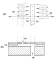
図4は、図3(a)〜(f)を用いて説明された本実施形態に係るインクジェット記録ヘッドを示す、上面から見た図および破線IVB−IVB位置における断面図(図2のものと同様)である。なお、311は、第二の単結晶シリコン層に形成された先導孔が存在した位置を示している。第二の単結晶シリコン層302は、主表面313が{110}面であり、供給口308の側面の、少なくとも2面315,316が、実質的に基板に垂直な(111)結晶面となる。このように、供給口308の側面を基板に垂直な(111)結晶面で形成することができることから、供給口308を高密度に配置することができることとなる。これにより、記録ヘッドの小型化が図られる。1枚のシリコンウエハから、複数の記録ヘッドを得ようとした場合、より多くの記録ヘッドを得ることができる。よって、生産性を工場させることができる。また、図4の上面(吐出口形成面)からから見た図に示すように、供給口308の溝の端部は、エッチングで形成する前に先導孔311が予め形成されていた位置である。エッチング前に先導孔311を形成しておくことによって、エッチングによる形状を定めることができる。
FIG. 4 is a top view of the ink jet recording head according to the present embodiment described with reference to FIGS. 3A to 3F and a cross-sectional view taken along the broken line IVB-IVB (as shown in FIG. 2). The same).
また、第一の単結晶シリコン層301は、主表面312が{100}面であり、液流路309の側面の、少なくとも3面(例示的に317、318、319)を、実質的に(111)結晶面からなる側面とすることができる。
Further, the first single
なお、駆動回路が、第一の単結晶シリコン層301にMOSトランジスタを具える場合、引き出し方位<100>の単結晶シリコン上に設けられるMOSトランジスタは電子移動度の関係からその表面積を小さくすることができる。その結果、さらに記録ヘッドの小型化が図ることができる。
Note that in the case where the driver circuit includes a MOS transistor in the first single
また、本実施形態では、主表面が{100}面の第一の単結晶シリコン層301と、主表面が{110}面である第二の単結晶シリコン層302とを用いた。しかしながら、主表面が{110}面の第一の単結晶シリコン層と、主表面が{100}面の第二の単結晶シリコン層とを用いてもよい。すなわち、第一の単結晶シリコン層301と第二の単結晶シリコン層302の少なくともいずれか一方の単結晶シリコン層に主表面が{110}面の単結晶シリコンを用いることにより、基板に垂直な(111)結晶面を形成することができればよい。第一の単結晶シリコン層に主表面が{110}面の単結晶シリコン層を用いることにより、液流路をエッチングにより形成するとき、基板に垂直な(111)結晶面を形成することができる。その結果、吐出口を高密度に配置することができ、記録ヘッドの吐出口表面の面積を小さくすることができる。
In the present embodiment, the first single
(第3の実施形態)
第2の実施形態では、第一の単結晶シリコン層と第二の単結晶シリコン層は、主表面が{100}面および主表面が{110}面の単結晶シリコン層を用いたが、本発明は、このような単結晶シリコン層の組み合わせに限定されない。
(Third embodiment)
In the second embodiment, the first single crystal silicon layer and the second single crystal silicon layer are single crystal silicon layers having a {100} plane and a {110} plane as the main surface. The invention is not limited to such a combination of single crystal silicon layers.
本実施形態では、第一の単結晶シリコン層(第一のシリコン層)に、主表面が{110}面の単結晶シリコン層を用い、第二の単結晶シリコン層(第二のシリコン層)に、同じく主表面が{110}面の単結晶シリコン層を用いる。これにより、液流路の配列の密度を高くすることができる。 In the present embodiment, a single crystal silicon layer having a {110} plane as a main surface is used as the first single crystal silicon layer (first silicon layer), and the second single crystal silicon layer (second silicon layer) is used. Similarly, a single crystal silicon layer having a main surface of {110} plane is used. Thereby, the density of the arrangement | sequence of a liquid flow path can be made high.
図5は、本発明の第3の実施形態のインクジェット記録ヘッドの製造方法を示す模式的断面図であり、図2と同様の断面である。 FIG. 5 is a schematic cross-sectional view showing the method of manufacturing the ink jet recording head according to the third embodiment of the present invention, and is the same cross section as FIG.
図5(a)は、厚さ25μmの主表面512が{110}面の第一の単結晶シリコン層501と、誘電体層503と、厚さ600μmの主表面513が{110}面の第二の単結晶シリコン層502からなる直径150mmのSOI基板514を示す図である。
FIG. 5A shows a first single
図5(b)は、第1の実施形態と同様に、裏面マスク層507、第二の単結晶シリコン層502、誘電体層503、犠牲層504、エッチングストップ層505、発熱抵抗体506、窒化シリコン層を蓄積した基板を示す図である。
FIG. 5B shows a
図5(c)は、供給口508が第一の単結晶シリコン層501に形成された基板を示す図である。
FIG. 5C shows a substrate in which the
図5(b)から(f)は、液流路509が形成された工程を示す図である。図5Eに示すように、エッチングにより、基板表面に対して約15°傾斜した側面515をもつ液流路509が形成されることとなる。
FIGS. 5B to 5F are diagrams showing a process in which the
図6は、図5(a)〜(f)を用いて製造工程を説明された本実施形態に係るインクジェット記録ヘッドを示す、図6(a)は基板を上面から見た図、であり、図6(b)は図6(a)の破線VIB−VIB位置における断面図である。なお、511は、第二の単結晶シリコン層に形成された先導孔が存在した位置を示している。
FIG. 6 shows the inkjet recording head according to the present embodiment, the manufacturing process of which has been described with reference to FIGS. 5A to 5F. FIG. 6A is a view of the substrate as viewed from above. FIG. 6B is a cross-sectional view taken along the broken line VIB-VIB in FIG. Note that
液流路509は少なくとも平行な2面の実質的に(111)結晶面からなる側面515,518を有している。このとき、基板に垂直な(111)結晶面が、供給口508の側面516,517に、また各々の液流路間の壁になるよう各層の結晶方位が選択されている。これにより、記録ヘッドのサイズを小さくし、かつ液流路が高密度に配置された記録ヘッドを作製することができる。
The
(第4の実施形態)
本実施形態の基板は、第2の実施形態において、図3(a)に示す状態で、第1の単結晶シリコン層301から誘電体層303に向かって、先導孔を形成するものである。犠牲層パターンの角が位置することとなる部分と、第一の単結晶シリコン層であって供給口の真上の部分とに、レーザー、RIE、イオンミリング等により誘電体層近くまでの深さの先導孔を形成する。これにより、特に、液流路の底面および奥側の面の形状を所望のものとすることができる。
(Fourth embodiment)
In the second embodiment, the substrate of this embodiment forms a leading hole from the first single
第2の実施形態における液流路は、基板表面に対して垂直な(111)結晶面と、基板表面に対して約15°傾斜している(111)結晶面とにより、形成されている。本実施形態では、さらに、先導孔を形成し、先導孔によりエッチング開始面を決定することにより、第2の実施形態における基板表面に対して約15°傾斜した(111)結晶面を、基板表面に対して垂直な(111)結晶面とすることができる。 The liquid flow path in the second embodiment is formed by a (111) crystal plane perpendicular to the substrate surface and a (111) crystal plane inclined by about 15 ° with respect to the substrate surface. In the present embodiment, a (111) crystal plane inclined by about 15 ° with respect to the substrate surface in the second embodiment is formed by forming a leading hole and determining an etching start surface by the leading hole. (111) crystal plane perpendicular to the surface.
図7は、本実施形態に係るインクジェット記録ヘッドを示す、基板を上面から見た図および破線VIIB−VIIB位置における断面図である。なお、711は第二の結晶シリコン層に形成された先導孔が存在した位置を示し、712は第一の結晶シリコン層に形成された先導孔が存在した位置を示している。先導孔712を形成することにより、図6で示す基板表面に対して約15°で傾斜している(111)結晶面515に相当する液流路の壁面を、図7に示す壁面715のように、基板表面に対して垂直な(111)結晶面とすることができる。その結果、流路部分の体積を変えずに、流路長さを小さくすることができ、さらに記録ヘッドの小型化を図ることができる。
FIG. 7 is a cross-sectional view of the ink jet recording head according to the present embodiment when the substrate is viewed from above and at the position of broken lines VIIB-VIIB.
201、301、501 第1の単結晶シリコン層
202、302、502 第2の単結晶シリコン層
203、303、503 誘電体層
205、305、505 エッチングストップ層
206、306、506 発熱抵抗体
207、307、507 裏面マスク層
208、308、508 供給口
209、309、509 液流路
210、310、510 吐出口
211 保護層
201, 301, 501 First single
Claims (9)
第一のシリコン層と、第二のシリコン層と、前記第一のシリコン層と前記第二のシリコン層の間に設けられた誘電体層と、を有するSOI基板を用意する工程と、
前記第一のシリコン層の上に、シリコンよりもエッチングされやすい材料により犠牲層を設ける工程と、
前記犠牲層を覆うようにエッチングストップ層を形成する工程と、
前記エッチングストップ層の上に、前記エネルギ発生素子を形成する工程と、
前記第二のシリコン層の一部と前記誘電体層の一部とを除去して、前記インク供給口を形成する工程と、
前記第一のシリコン層に対して、エッチングを行い、被エッチング領域を前記犠牲層に到達させ、前記犠牲層を除去して前記流路を形成する工程と、
前記エッチングストップ層の一部を除去して前記吐出口を形成する工程と、
を有することを特徴とするインクジェット記録ヘッドの製造方法。 An ink ejection port, an energy generating element that generates energy used to eject ink from the ejection port, an ink flow channel communicating with the ejection port, and an ink communicating with the flow channel In an ink jet recording head manufacturing method comprising:
Providing an SOI substrate having a first silicon layer, a second silicon layer, and a dielectric layer provided between the first silicon layer and the second silicon layer;
Providing a sacrificial layer on the first silicon layer with a material that is easier to etch than silicon;
Forming an etching stop layer to cover the sacrificial layer;
Forming the energy generating element on the etching stop layer ;
Removing a part of the second silicon layer and a part of the dielectric layer to form the ink supply port;
Etching the first silicon layer, causing the etched region to reach the sacrificial layer, removing the sacrificial layer, and forming the flow path;
Removing a part of the etching stop layer to form the discharge port;
An ink jet recording head manufacturing method comprising:
前記基板は、第一のシリコン層と、第二のシリコン層とを具え、
前記第一のシリコン層には、前記吐出口に連通する液流路が形成され、
前記第二のシリコン層には、前記流路と連通しインクを供給するための供給口が形成され、
前記液流路は、少なくとも2つの(111)結晶面で構成され、前記供給口は、少なくとも2つの(111)結晶面で構成され、前記液流路および前記供給口の少なくとも一方の前記結晶面は、前記基板表面と垂直であることを特徴とするインクジェット記録ヘッド。 In an ink jet recording head comprising a substrate surface including an ink ejection port and an energy generating element that generates energy used to eject ink from the ejection port.
The substrate comprises a first silicon layer and a second silicon layer,
In the first silicon layer, a liquid flow path communicating with the discharge port is formed,
A supply port for supplying ink in communication with the flow path is formed in the second silicon layer,
The liquid channel is configured by at least two (111) crystal planes, and the supply port is configured by at least two (111) crystal planes, and the crystal plane of at least one of the liquid channel and the supply port. Is an inkjet recording head characterized by being perpendicular to the substrate surface.
前記基板は、第一のシリコン層と、第二のシリコン層とを具え、
前記第一のシリコン層には、前記吐出口に連通するインクの流路が形成され、
前記第二のシリコン層には、前記流路と連通し前記インクを供給するための供給口が形成され、
前記第一のシリコン層と前記第二のシリコン層とは、引き出し方位が異なることを特徴とするインクジェット記録ヘッド。 In an ink jet recording head comprising a substrate including an ink ejection port and an energy generating element that generates energy used to eject ink from the ejection port.
The substrate comprises a first silicon layer and a second silicon layer,
In the first silicon layer, an ink flow path communicating with the ejection port is formed,
A supply port for supplying the ink in communication with the flow path is formed in the second silicon layer,
An ink jet recording head, wherein the first silicon layer and the second silicon layer have different drawing orientations.
Priority Applications (1)
| Application Number | Priority Date | Filing Date | Title |
|---|---|---|---|
| JP2007266703A JP5111047B2 (en) | 2006-10-12 | 2007-10-12 | Ink jet recording head and method of manufacturing ink jet recording head. |
Applications Claiming Priority (5)
| Application Number | Priority Date | Filing Date | Title |
|---|---|---|---|
| JP2006278785 | 2006-10-12 | ||
| JP2006278786 | 2006-10-12 | ||
| JP2006278785 | 2006-10-12 | ||
| JP2006278786 | 2006-10-12 | ||
| JP2007266703A JP5111047B2 (en) | 2006-10-12 | 2007-10-12 | Ink jet recording head and method of manufacturing ink jet recording head. |
Publications (3)
| Publication Number | Publication Date |
|---|---|
| JP2008114589A JP2008114589A (en) | 2008-05-22 |
| JP2008114589A5 JP2008114589A5 (en) | 2010-11-11 |
| JP5111047B2 true JP5111047B2 (en) | 2012-12-26 |
Family
ID=39302691
Family Applications (1)
| Application Number | Title | Priority Date | Filing Date |
|---|---|---|---|
| JP2007266703A Expired - Fee Related JP5111047B2 (en) | 2006-10-12 | 2007-10-12 | Ink jet recording head and method of manufacturing ink jet recording head. |
Country Status (5)
| Country | Link |
|---|---|
| US (1) | US8562845B2 (en) |
| JP (1) | JP5111047B2 (en) |
| KR (1) | KR100955963B1 (en) |
| CN (1) | CN101161459B (en) |
| TW (1) | TWI333897B (en) |
Families Citing this family (14)
| Publication number | Priority date | Publication date | Assignee | Title |
|---|---|---|---|---|
| KR20090058225A (en) * | 2007-12-04 | 2009-06-09 | 삼성전자주식회사 | Inkjet printhead and method of manufacturing the same |
| KR20100011652A (en) * | 2008-07-25 | 2010-02-03 | 삼성전자주식회사 | Inkjet printhead and method of manufacturing the same |
| JP5335396B2 (en) * | 2008-12-16 | 2013-11-06 | キヤノン株式会社 | Method for manufacturing ink jet recording head |
| JP4557081B2 (en) * | 2009-01-21 | 2010-10-06 | ダイキン工業株式会社 | Biting type pipe connection structure, valve, biting type pipe fitting and refrigeration system |
| US8012773B2 (en) * | 2009-06-11 | 2011-09-06 | Canon Kabushiki Kaisha | Method for manufacturing liquid discharge head |
| GB0919744D0 (en) * | 2009-11-11 | 2009-12-30 | Queen Mary & Westfield College | Electrospray emitter and method of manufacture |
| JP5709536B2 (en) * | 2010-01-14 | 2015-04-30 | キヤノン株式会社 | Silicon substrate processing method |
| JP2011199673A (en) * | 2010-03-19 | 2011-10-06 | Seiko Instruments Inc | Crystal substrate etching method, piezoelectric vibrating reed, piezoelectric vibrator, oscillator, electronic device, and radio-controlled timepiece |
| EP2547529B1 (en) | 2010-03-31 | 2019-09-04 | Canon Kabushiki Kaisha | Liquid discharge head manufacturing method |
| KR20120002688A (en) * | 2010-07-01 | 2012-01-09 | 삼성전기주식회사 | Nozzle plate and method for manufacturing the nozzle palte, and inkjet printer head with the nozzle plate |
| US8690295B2 (en) | 2010-09-15 | 2014-04-08 | Hewlett-Packard Development Company, L.P. | Fluid nozzle array |
| WO2012105935A1 (en) * | 2011-01-31 | 2012-08-09 | Hewlett-Packard Development Company, L.P. | Fluid ejection assembly and related methods |
| JP5182392B2 (en) | 2011-03-31 | 2013-04-17 | ブラザー工業株式会社 | Recording device |
| JP5814963B2 (en) * | 2013-03-08 | 2015-11-17 | 東芝テック株式会社 | Ink jet head, ink jet recording apparatus, and method of manufacturing ink jet head |
Family Cites Families (27)
| Publication number | Priority date | Publication date | Assignee | Title |
|---|---|---|---|---|
| US6019457A (en) * | 1991-01-30 | 2000-02-01 | Canon Information Systems Research Australia Pty Ltd. | Ink jet print device and print head or print apparatus using the same |
| JP3221474B2 (en) * | 1994-04-05 | 2001-10-22 | セイコーエプソン株式会社 | Inkjet print head |
| KR100311880B1 (en) | 1996-11-11 | 2001-12-20 | 미다라이 후지오 | Method of producing a through-hole, silicon substrate having a through-hole, device using such a substrate, method of producing an ink-jet print head, and ink-jet print head |
| US6234608B1 (en) * | 1997-06-05 | 2001-05-22 | Xerox Corporation | Magnetically actuated ink jet printing device |
| US6264849B1 (en) * | 1997-07-15 | 2001-07-24 | Silverbrook Research Pty Ltd | Method of manufacture of a bend actuator direct ink supply ink jet printer |
| US6303042B1 (en) | 1999-03-02 | 2001-10-16 | Eastman Kodak Company | Making ink jet nozzle plates |
| JP3379580B2 (en) * | 2000-04-10 | 2003-02-24 | セイコーエプソン株式会社 | Ink jet recording head, method of manufacturing the same, and ink jet recording apparatus |
| JP3760981B2 (en) | 1999-11-15 | 2006-03-29 | セイコーエプソン株式会社 | Inkjet recording head and inkjet recording apparatus |
| JP3494219B2 (en) * | 1999-11-15 | 2004-02-09 | セイコーエプソン株式会社 | Ink jet recording head |
| JP2001171120A (en) * | 1999-12-17 | 2001-06-26 | Canon Inc | Recording head and recorder |
| JP2001301179A (en) * | 2000-02-18 | 2001-10-30 | Seiko Epson Corp | Method for manufacturing recording head and recording head |
| US6398348B1 (en) * | 2000-09-05 | 2002-06-04 | Hewlett-Packard Company | Printing structure with insulator layer |
| DE60128781T2 (en) | 2000-12-15 | 2008-02-07 | Samsung Electronics Co., Ltd., Suwon | Bubble-powered inkjet printhead and associated Hertsellverfahren |
| JP2004066537A (en) | 2002-08-02 | 2004-03-04 | Seiko Epson Corp | Process for manufacturing liquid ejection head |
| KR100499132B1 (en) * | 2002-10-24 | 2005-07-04 | 삼성전자주식회사 | Inkjet printhead and manufacturing method thereof |
| CN100355573C (en) * | 2002-12-27 | 2007-12-19 | 佳能株式会社 | Ink-jet recording head and mfg. method, and substrate for mfg. ink-jet recording head |
| US7323115B2 (en) * | 2003-02-13 | 2008-01-29 | Canon Kabushiki Kaisha | Substrate processing method and ink jet recording head substrate manufacturing method |
| US7036913B2 (en) * | 2003-05-27 | 2006-05-02 | Samsung Electronics Co., Ltd. | Ink-jet printhead |
| KR100590527B1 (en) | 2003-05-27 | 2006-06-15 | 삼성전자주식회사 | Inkjet printhead and manufacturing method thereof |
| JP4522086B2 (en) * | 2003-12-15 | 2010-08-11 | キヤノン株式会社 | Beam, beam manufacturing method, ink jet recording head including beam, and ink jet recording head manufacturing method |
| CN1325270C (en) | 2003-12-23 | 2007-07-11 | 明基电通股份有限公司 | Method of expanding fluid channel |
| KR100641357B1 (en) * | 2004-08-26 | 2006-11-01 | 삼성전자주식회사 | Ink-jet print head and the fabricating method thereof |
| JP2006130766A (en) * | 2004-11-05 | 2006-05-25 | Canon Inc | Substrate for liquid delivering head and its manufacturing method |
| US7255425B2 (en) | 2004-12-02 | 2007-08-14 | Taiwan Semiconductor Manufacturing Co., Ltd. | Ink-channel wafer integrated with CMOS wafer for inkjet printhead and fabrication method thereof |
| JP2006224590A (en) | 2005-02-21 | 2006-08-31 | Canon Inc | Method for manufacturing inkjet recording head |
| JP4766658B2 (en) * | 2005-05-10 | 2011-09-07 | キヤノン株式会社 | Liquid discharge head and manufacturing method thereof |
| US7637013B2 (en) * | 2005-08-23 | 2009-12-29 | Canon Kabushiki Kaisha | Method of manufacturing ink jet recording head |
-
2007
- 2007-10-05 US US11/868,113 patent/US8562845B2/en not_active Expired - Fee Related
- 2007-10-09 TW TW096137861A patent/TWI333897B/en not_active IP Right Cessation
- 2007-10-11 KR KR1020070102510A patent/KR100955963B1/en active IP Right Grant
- 2007-10-12 CN CN2007101822107A patent/CN101161459B/en not_active Expired - Fee Related
- 2007-10-12 JP JP2007266703A patent/JP5111047B2/en not_active Expired - Fee Related
Also Published As
| Publication number | Publication date |
|---|---|
| KR100955963B1 (en) | 2010-05-04 |
| JP2008114589A (en) | 2008-05-22 |
| CN101161459A (en) | 2008-04-16 |
| TWI333897B (en) | 2010-12-01 |
| CN101161459B (en) | 2010-06-09 |
| US20080088674A1 (en) | 2008-04-17 |
| US8562845B2 (en) | 2013-10-22 |
| TW200902329A (en) | 2009-01-16 |
| KR20080033111A (en) | 2008-04-16 |
Similar Documents
| Publication | Publication Date | Title |
|---|---|---|
| JP5111047B2 (en) | Ink jet recording head and method of manufacturing ink jet recording head. | |
| EP1693206B1 (en) | Piezoelectric inkjet printhead and method of manufacturing the same | |
| JP4593902B2 (en) | Substrate with slot and formation method | |
| CN105102230B (en) | Fluid ejection apparatus | |
| JP2009061669A (en) | Manufacturing method of inkjet recording head substrate, inkjet recording head and its manufacturing method | |
| JPH11227208A (en) | Liquid jet recorder and manufacture thereof | |
| US7473649B2 (en) | Methods for controlling feature dimensions in crystalline substrates | |
| US8808555B2 (en) | Method of manufacturing substrate for liquid discharge head | |
| JP6900182B2 (en) | Liquid discharge head and manufacturing method of liquid discharge head | |
| JP5038054B2 (en) | Liquid discharge head and manufacturing method thereof | |
| JP2010142972A (en) | Method for manufacturing inkjet recording head | |
| JP2008087371A (en) | Manufacturing method of liquid discharge head, and liquid discharge head | |
| US9669628B2 (en) | Liquid ejection head substrate, method of manufacturing the same, and method of processing silicon substrate | |
| JP2003011365A (en) | Ink jet head and its manufacturing method | |
| JP5511202B2 (en) | Piezoelectric element, liquid discharge head using the same, and recording apparatus | |
| JP2007290203A (en) | Inkjet recording head and its manufacturing method | |
| JPH07276626A (en) | Ink jet type printing head | |
| JP2004142462A (en) | Inkjet printhead and its manufacturing method | |
| US6908564B2 (en) | Liquid discharge head and method of manufacturing the same | |
| JP4671330B2 (en) | Method for manufacturing ink jet recording head | |
| JP2007210176A (en) | Method for processing silicon substrate and method for manufacturing liquid jet head | |
| JP5807362B2 (en) | Method for manufacturing liquid jet head | |
| JP4979488B2 (en) | Liquid ejection head and recording apparatus | |
| KR100474827B1 (en) | A piezoelectric impulse ink-jet printhead and a method for fabricating the same | |
| JP2006218735A (en) | Inkjet recording head and its manufacturing method |
Legal Events
| Date | Code | Title | Description |
|---|---|---|---|
| A521 | Request for written amendment filed |
Free format text: JAPANESE INTERMEDIATE CODE: A523 Effective date: 20100929 |
|
| A621 | Written request for application examination |
Free format text: JAPANESE INTERMEDIATE CODE: A621 Effective date: 20100929 |
|
| RD02 | Notification of acceptance of power of attorney |
Free format text: JAPANESE INTERMEDIATE CODE: A7422 Effective date: 20101106 |
|
| A977 | Report on retrieval |
Free format text: JAPANESE INTERMEDIATE CODE: A971007 Effective date: 20120613 |
|
| A131 | Notification of reasons for refusal |
Free format text: JAPANESE INTERMEDIATE CODE: A131 Effective date: 20120626 |
|
| A521 | Request for written amendment filed |
Free format text: JAPANESE INTERMEDIATE CODE: A523 Effective date: 20120827 |
|
| TRDD | Decision of grant or rejection written | ||
| A01 | Written decision to grant a patent or to grant a registration (utility model) |
Free format text: JAPANESE INTERMEDIATE CODE: A01 Effective date: 20120911 |
|
| A01 | Written decision to grant a patent or to grant a registration (utility model) |
Free format text: JAPANESE INTERMEDIATE CODE: A01 |
|
| A61 | First payment of annual fees (during grant procedure) |
Free format text: JAPANESE INTERMEDIATE CODE: A61 Effective date: 20121009 |
|
| FPAY | Renewal fee payment (event date is renewal date of database) |
Free format text: PAYMENT UNTIL: 20151019 Year of fee payment: 3 |
|
| R151 | Written notification of patent or utility model registration |
Ref document number: 5111047 Country of ref document: JP Free format text: JAPANESE INTERMEDIATE CODE: R151 |
|
| FPAY | Renewal fee payment (event date is renewal date of database) |
Free format text: PAYMENT UNTIL: 20151019 Year of fee payment: 3 |
|
| LAPS | Cancellation because of no payment of annual fees |