JP5106536B2 - Air conditioner - Google Patents
Air conditioner Download PDFInfo
- Publication number
- JP5106536B2 JP5106536B2 JP2009529893A JP2009529893A JP5106536B2 JP 5106536 B2 JP5106536 B2 JP 5106536B2 JP 2009529893 A JP2009529893 A JP 2009529893A JP 2009529893 A JP2009529893 A JP 2009529893A JP 5106536 B2 JP5106536 B2 JP 5106536B2
- Authority
- JP
- Japan
- Prior art keywords
- refrigerant
- pressure
- load
- bypass
- compressor
- Prior art date
- Legal status (The legal status is an assumption and is not a legal conclusion. Google has not performed a legal analysis and makes no representation as to the accuracy of the status listed.)
- Active
Links
Images


Classifications
-
- F—MECHANICAL ENGINEERING; LIGHTING; HEATING; WEAPONS; BLASTING
- F25—REFRIGERATION OR COOLING; COMBINED HEATING AND REFRIGERATION SYSTEMS; HEAT PUMP SYSTEMS; MANUFACTURE OR STORAGE OF ICE; LIQUEFACTION SOLIDIFICATION OF GASES
- F25B—REFRIGERATION MACHINES, PLANTS OR SYSTEMS; COMBINED HEATING AND REFRIGERATION SYSTEMS; HEAT PUMP SYSTEMS
- F25B13/00—Compression machines, plants or systems, with reversible cycle
-
- F—MECHANICAL ENGINEERING; LIGHTING; HEATING; WEAPONS; BLASTING
- F25—REFRIGERATION OR COOLING; COMBINED HEATING AND REFRIGERATION SYSTEMS; HEAT PUMP SYSTEMS; MANUFACTURE OR STORAGE OF ICE; LIQUEFACTION SOLIDIFICATION OF GASES
- F25B—REFRIGERATION MACHINES, PLANTS OR SYSTEMS; COMBINED HEATING AND REFRIGERATION SYSTEMS; HEAT PUMP SYSTEMS
- F25B2313/00—Compression machines, plants or systems with reversible cycle not otherwise provided for
- F25B2313/006—Compression machines, plants or systems with reversible cycle not otherwise provided for two pipes connecting the outdoor side to the indoor side with multiple indoor units
-
- F—MECHANICAL ENGINEERING; LIGHTING; HEATING; WEAPONS; BLASTING
- F25—REFRIGERATION OR COOLING; COMBINED HEATING AND REFRIGERATION SYSTEMS; HEAT PUMP SYSTEMS; MANUFACTURE OR STORAGE OF ICE; LIQUEFACTION SOLIDIFICATION OF GASES
- F25B—REFRIGERATION MACHINES, PLANTS OR SYSTEMS; COMBINED HEATING AND REFRIGERATION SYSTEMS; HEAT PUMP SYSTEMS
- F25B2313/00—Compression machines, plants or systems with reversible cycle not otherwise provided for
- F25B2313/023—Compression machines, plants or systems with reversible cycle not otherwise provided for using multiple indoor units
- F25B2313/0231—Compression machines, plants or systems with reversible cycle not otherwise provided for using multiple indoor units with simultaneous cooling and heating
-
- F—MECHANICAL ENGINEERING; LIGHTING; HEATING; WEAPONS; BLASTING
- F25—REFRIGERATION OR COOLING; COMBINED HEATING AND REFRIGERATION SYSTEMS; HEAT PUMP SYSTEMS; MANUFACTURE OR STORAGE OF ICE; LIQUEFACTION SOLIDIFICATION OF GASES
- F25B—REFRIGERATION MACHINES, PLANTS OR SYSTEMS; COMBINED HEATING AND REFRIGERATION SYSTEMS; HEAT PUMP SYSTEMS
- F25B2313/00—Compression machines, plants or systems with reversible cycle not otherwise provided for
- F25B2313/023—Compression machines, plants or systems with reversible cycle not otherwise provided for using multiple indoor units
- F25B2313/0233—Compression machines, plants or systems with reversible cycle not otherwise provided for using multiple indoor units in parallel arrangements
-
- F—MECHANICAL ENGINEERING; LIGHTING; HEATING; WEAPONS; BLASTING
- F25—REFRIGERATION OR COOLING; COMBINED HEATING AND REFRIGERATION SYSTEMS; HEAT PUMP SYSTEMS; MANUFACTURE OR STORAGE OF ICE; LIQUEFACTION SOLIDIFICATION OF GASES
- F25B—REFRIGERATION MACHINES, PLANTS OR SYSTEMS; COMBINED HEATING AND REFRIGERATION SYSTEMS; HEAT PUMP SYSTEMS
- F25B2313/00—Compression machines, plants or systems with reversible cycle not otherwise provided for
- F25B2313/025—Compression machines, plants or systems with reversible cycle not otherwise provided for using multiple outdoor units
- F25B2313/0253—Compression machines, plants or systems with reversible cycle not otherwise provided for using multiple outdoor units in parallel arrangements
-
- F—MECHANICAL ENGINEERING; LIGHTING; HEATING; WEAPONS; BLASTING
- F25—REFRIGERATION OR COOLING; COMBINED HEATING AND REFRIGERATION SYSTEMS; HEAT PUMP SYSTEMS; MANUFACTURE OR STORAGE OF ICE; LIQUEFACTION SOLIDIFICATION OF GASES
- F25B—REFRIGERATION MACHINES, PLANTS OR SYSTEMS; COMBINED HEATING AND REFRIGERATION SYSTEMS; HEAT PUMP SYSTEMS
- F25B2313/00—Compression machines, plants or systems with reversible cycle not otherwise provided for
- F25B2313/027—Compression machines, plants or systems with reversible cycle not otherwise provided for characterised by the reversing means
- F25B2313/0272—Compression machines, plants or systems with reversible cycle not otherwise provided for characterised by the reversing means using bridge circuits of one-way valves
-
- F—MECHANICAL ENGINEERING; LIGHTING; HEATING; WEAPONS; BLASTING
- F25—REFRIGERATION OR COOLING; COMBINED HEATING AND REFRIGERATION SYSTEMS; HEAT PUMP SYSTEMS; MANUFACTURE OR STORAGE OF ICE; LIQUEFACTION SOLIDIFICATION OF GASES
- F25B—REFRIGERATION MACHINES, PLANTS OR SYSTEMS; COMBINED HEATING AND REFRIGERATION SYSTEMS; HEAT PUMP SYSTEMS
- F25B2313/00—Compression machines, plants or systems with reversible cycle not otherwise provided for
- F25B2313/027—Compression machines, plants or systems with reversible cycle not otherwise provided for characterised by the reversing means
- F25B2313/02741—Compression machines, plants or systems with reversible cycle not otherwise provided for characterised by the reversing means using one four-way valve
-
- F—MECHANICAL ENGINEERING; LIGHTING; HEATING; WEAPONS; BLASTING
- F25—REFRIGERATION OR COOLING; COMBINED HEATING AND REFRIGERATION SYSTEMS; HEAT PUMP SYSTEMS; MANUFACTURE OR STORAGE OF ICE; LIQUEFACTION SOLIDIFICATION OF GASES
- F25B—REFRIGERATION MACHINES, PLANTS OR SYSTEMS; COMBINED HEATING AND REFRIGERATION SYSTEMS; HEAT PUMP SYSTEMS
- F25B2400/00—General features or devices for refrigeration machines, plants or systems, combined heating and refrigeration systems or heat-pump systems, i.e. not limited to a particular subgroup of F25B
- F25B2400/23—Separators
-
- F—MECHANICAL ENGINEERING; LIGHTING; HEATING; WEAPONS; BLASTING
- F25—REFRIGERATION OR COOLING; COMBINED HEATING AND REFRIGERATION SYSTEMS; HEAT PUMP SYSTEMS; MANUFACTURE OR STORAGE OF ICE; LIQUEFACTION SOLIDIFICATION OF GASES
- F25B—REFRIGERATION MACHINES, PLANTS OR SYSTEMS; COMBINED HEATING AND REFRIGERATION SYSTEMS; HEAT PUMP SYSTEMS
- F25B2600/00—Control issues
- F25B2600/02—Compressor control
- F25B2600/025—Compressor control by controlling speed
- F25B2600/0253—Compressor control by controlling speed with variable speed
-
- F—MECHANICAL ENGINEERING; LIGHTING; HEATING; WEAPONS; BLASTING
- F25—REFRIGERATION OR COOLING; COMBINED HEATING AND REFRIGERATION SYSTEMS; HEAT PUMP SYSTEMS; MANUFACTURE OR STORAGE OF ICE; LIQUEFACTION SOLIDIFICATION OF GASES
- F25B—REFRIGERATION MACHINES, PLANTS OR SYSTEMS; COMBINED HEATING AND REFRIGERATION SYSTEMS; HEAT PUMP SYSTEMS
- F25B2600/00—Control issues
- F25B2600/25—Control of valves
- F25B2600/2501—Bypass valves
-
- F—MECHANICAL ENGINEERING; LIGHTING; HEATING; WEAPONS; BLASTING
- F25—REFRIGERATION OR COOLING; COMBINED HEATING AND REFRIGERATION SYSTEMS; HEAT PUMP SYSTEMS; MANUFACTURE OR STORAGE OF ICE; LIQUEFACTION SOLIDIFICATION OF GASES
- F25B—REFRIGERATION MACHINES, PLANTS OR SYSTEMS; COMBINED HEATING AND REFRIGERATION SYSTEMS; HEAT PUMP SYSTEMS
- F25B49/00—Arrangement or mounting of control or safety devices
- F25B49/02—Arrangement or mounting of control or safety devices for compression type machines, plants or systems
- F25B49/027—Condenser control arrangements
-
- Y—GENERAL TAGGING OF NEW TECHNOLOGICAL DEVELOPMENTS; GENERAL TAGGING OF CROSS-SECTIONAL TECHNOLOGIES SPANNING OVER SEVERAL SECTIONS OF THE IPC; TECHNICAL SUBJECTS COVERED BY FORMER USPC CROSS-REFERENCE ART COLLECTIONS [XRACs] AND DIGESTS
- Y02—TECHNOLOGIES OR APPLICATIONS FOR MITIGATION OR ADAPTATION AGAINST CLIMATE CHANGE
- Y02B—CLIMATE CHANGE MITIGATION TECHNOLOGIES RELATED TO BUILDINGS, e.g. HOUSING, HOUSE APPLIANCES OR RELATED END-USER APPLICATIONS
- Y02B30/00—Energy efficient heating, ventilation or air conditioning [HVAC]
- Y02B30/70—Efficient control or regulation technologies, e.g. for control of refrigerant flow, motor or heating
Landscapes
- Engineering & Computer Science (AREA)
- Physics & Mathematics (AREA)
- Mechanical Engineering (AREA)
- Thermal Sciences (AREA)
- General Engineering & Computer Science (AREA)
- Compression-Type Refrigeration Machines With Reversible Cycles (AREA)
- Air Conditioning Control Device (AREA)
Description
本発明は、冷凍サイクル(ヒートポンプサイクル)を利用して冷暖房運転を行い、空気調和を行う空気調和装置に関するものである。特に室内などに設けられる負荷側ユニットにおいて、熱交換できる熱量が小さい場合に発生しやすくなる、圧縮機の吐出側における冷媒圧力の異常な上昇を抑えるための機器(手段)構成に関するものである。 The present invention relates to an air conditioner that performs air conditioning using a refrigeration cycle (heat pump cycle) to perform air conditioning. In particular, the present invention relates to a device (means) configuration for suppressing an abnormal increase in refrigerant pressure on the discharge side of a compressor, which is likely to occur when the amount of heat that can be exchanged with heat is small in a load-side unit provided in a room or the like.
冷暖房運転を行って室内などの空気調和(室温調整)を行う空気調和装置において、夏季のような外気の温度が高い場合でも暖房運転を行う場合がある。例えば、複数の負荷側ユニットが、ユニットごとに冷房運転、暖房運転を行う冷暖混在運転が可能な空気調和装置では、空気調和装置に供え付けられたリモコンの設定温度と負荷側ユニット周辺の気温とに応じて、それぞれ冷房運転、暖房運転を自動的に判断して運転を行うようにできることが多い。ただ、外気の温度が高い場合に暖房運転を行っている負荷側ユニットの数は一般的には少ない。また、暖房運転を行っている負荷側ユニットにおける空調負荷(その負荷側ユニットが必要とする熱量。以下、負荷という)も小さく、負荷側ユニットが有する熱交換器(以下、負荷側熱交換器という)において熱交換される熱量も少なくなる。さらに、上記のような冷暖混在運転が可能な空気調和装置においては、負荷側ユニットの小型化、多様化などを図るため、負荷側熱交換器が熱交換できる熱量(以下、これを熱交換容量という)も小さくなる傾向にある。 In an air conditioner that performs air conditioning (room temperature adjustment) in a room or the like by performing an air conditioning operation, the heating operation may be performed even when the temperature of the outside air is high, such as in summer. For example, in an air conditioner in which a plurality of load-side units can perform cooling and heating mixed operation in which cooling operation and heating operation are performed for each unit, the set temperature of a remote controller provided in the air conditioner and the temperature around the load-side unit Depending on the situation, it is often possible to automatically determine the cooling operation and the heating operation, respectively. However, the number of load-side units that perform heating operation when the temperature of the outside air is high is generally small. In addition, the air conditioning load (the amount of heat required by the load side unit, hereinafter referred to as load) in the load side unit performing the heating operation is small, and the heat exchanger (hereinafter referred to as load side heat exchanger) that the load side unit has. ) Also reduces the amount of heat exchanged. Furthermore, in an air conditioner capable of mixed cooling and heating as described above, the amount of heat that can be exchanged by the load-side heat exchanger (hereinafter referred to as heat exchange capacity) in order to reduce the size and diversification of the load-side unit. Tend to be smaller.
一方、空気調和装置において暖房運転を行うと、室外などに設けられた熱源側ユニットが有する熱交換器(以下、熱源側熱交換器という)は蒸発器として機能する。外気の温度が高い場合には、熱源側熱交換器内を通過する冷媒が外気から吸収する熱量(吸熱量)が大きくなる。これにより、熱源側熱交換器の二次側(蒸発器として機能する場合には冷媒の出口側となる)におけるガス(気体)冷媒の過熱度が増大して過熱蒸気となり、圧縮機は温度の高いガス冷媒を吸入する。そのため、圧縮機は過熱される。また、ガス冷媒の温度が高いため吐出する冷媒の圧力も上昇しやすい。 On the other hand, when a heating operation is performed in the air conditioner, a heat exchanger (hereinafter referred to as a heat source side heat exchanger) included in a heat source side unit provided outside the room functions as an evaporator. When the temperature of the outside air is high, the amount of heat (heat absorption amount) absorbed from the outside air by the refrigerant passing through the heat source side heat exchanger increases. As a result, the superheat degree of the gas (gas) refrigerant on the secondary side of the heat source side heat exchanger (or the refrigerant outlet side when functioning as an evaporator) increases to superheated steam, and the compressor Inhales high gas refrigerant. Therefore, the compressor is overheated. Further, since the temperature of the gas refrigerant is high, the pressure of the discharged refrigerant is likely to increase.
このように、熱交換容量が小さい、吸入する冷媒の温度が高いなどの状態では、圧縮機が吐出する冷媒の圧力が異常に上昇し、これによっても圧縮機がさらに過熱される。これにより、圧縮機の異常停止などがおこり、エネルギ消費効率など、運転効率が悪くなる。また、異常な圧力上昇は、機器、配管に悪影響を与える。そこで、インバータ回路を有する圧縮機を用いて、圧縮機の駆動周波数を低減させ、冷凍サイクルを循環する(単位時間あたりの)冷媒量を減少させる。そして、負荷に合わせた冷暖房能力(負荷側ユニット側に供給する時間当たりの熱量。以下、これらを能力という)を供給するようにし、吐出側の圧力の上昇を抑えるようにする方法が提案されている(たとえば、特許文献1参照)。
しかし、一般的に、たとえ、インバータ回路により圧縮機の駆動周波数を低減させたとしても限界があり、例えば、圧縮機が駆動を維持するために必要な最低駆動周波数がある。最低駆動周波数で駆動させたときの能力が負荷側ユニットにおいて処理しきれなければ、能力以上の冷媒が供給されて能力過多になり、吐出側の圧力の上昇を招くことになる。また、負荷側ユニットにおいては、要求以上の熱量がすぐに供給されることになる。そのため、例えば運転の開始、一時停止などが頻繁に行われ、これが消費電力を高め、エネルギ消費効率を下げる原因となる。 However, in general, even if the drive frequency of the compressor is reduced by an inverter circuit, there is a limit, for example, there is a minimum drive frequency necessary for the compressor to keep driving. If the capacity when driven at the minimum driving frequency cannot be fully processed by the load side unit, the refrigerant exceeding the capacity is supplied, the capacity becomes excessive, and the pressure on the discharge side increases. Moreover, in the load side unit, the amount of heat more than required is supplied immediately. For this reason, for example, start and stop of operation are frequently performed, which increases power consumption and decreases energy consumption efficiency.
本発明は、以上のような問題を解決するためになされたものである。例えば冷暖混在運転可能な空気調和装置において、暖房運転する熱源側ユニットの数が少ない、熱交換容量が小さいなどの場合でも、適量の冷媒量を循環させるなどして、負荷に見合った能力を供給する。そして、安全運転、装置の保護を図り、冷媒を効率よく凝縮できるようにしてエネルギ効率のよい運転を行うことができる空気調和装置を得ることを目的とする。 The present invention has been made to solve the above problems. For example, in an air conditioner that can be operated in a mixed cooling and heating mode, even if the number of heat source side units that perform heating operation is small or the heat exchange capacity is small, an appropriate amount of refrigerant is circulated to supply the capacity appropriate for the load. To do. And it aims at safe operation, protection of an apparatus, and obtaining the air conditioning apparatus which can perform an efficient operation | movement so that a refrigerant | coolant can be condensed efficiently.
本発明に係る空気調和装置は、熱源側熱交換器及び圧縮機を有する熱源側ユニットと、負荷側絞り装置及び負荷側熱交換器を有する複数の負荷側ユニットと、暖房運転を行う負荷側ユニットに気体の冷媒を供給し、冷房運転を行う負荷側ユニットに液体の冷媒を供給するための気液分離器を有する冷暖分岐ユニットとを配管接続して冷媒回路を構成し、冷媒を循環させて運転を行う冷暖房混在運転可能な空気調和装置であって、圧縮機が吐出した冷媒が分流するバイパスを形成するバイパス管と、開閉によりバイパス管への冷媒の分流を制御するバイパス用開閉弁と、熱源側熱交換器を蒸発器とし、負荷側熱交換器の少なくとも1つが凝縮器として機能する運転を行う際、圧縮機の吐出側における冷媒圧力の異常上昇又は異常上昇のおそれがあるかどうかを判断し、異常上昇又は異常上昇のおそれがあると判断すると、バイパス用開閉弁を開放させてバイパス管に冷媒を分流をさせる処理を行う制御手段と、を備え、熱源側熱交換器は、複数の熱交換器を冷媒回路に対して並列に配管接続して構成しており、バイパス管を通過した冷媒が、複数の熱交換器のうちのいずれかの熱交換器を通過し、顕熱が除去されて圧縮機の吸入側に戻るように、バイパス管の一端と、いずれかの熱交換器に通じる配管とを連通させる。
An air conditioner according to the present invention includes a heat source side unit having a heat source side heat exchanger and a compressor, a plurality of load side units having a load side expansion device and a load side heat exchanger, and a load side unit performing a heating operation. A refrigerant circuit is configured by connecting a cooling / heating branch unit having a gas-liquid separator for supplying a liquid refrigerant to a load-side unit that performs cooling operation and having a gas-liquid separator for circulating the refrigerant. An air-conditioning apparatus capable of operating in an air-conditioning mixed operation, wherein a bypass pipe that forms a bypass to which refrigerant discharged from a compressor diverts, and a bypass on-off valve that controls opening and closing of the refrigerant to the bypass pipe, When performing an operation in which the heat source side heat exchanger is an evaporator and at least one of the load side heat exchangers functions as a condenser, there is a risk of abnormal rise or abnormal rise in refrigerant pressure on the discharge side of the compressor. Determining whether, when it is determined that there is a risk of abnormal rise or abnormal increase, and a control unit that performs processing for the diverts coolant to the bypass pipe by opening the bypass opening and closing valve, the heat source-side heat exchanger The heat exchanger is configured by connecting a plurality of heat exchangers in parallel to the refrigerant circuit, and the refrigerant that has passed through the bypass pipe passes through any one of the heat exchangers. Then, one end of the bypass pipe is connected to a pipe leading to one of the heat exchangers so that the sensible heat is removed and returned to the suction side of the compressor.
以上のように、熱源側ユニットにバイパス管、バイパス用開閉弁を設け、圧縮機が吐出した冷媒を分流させることができるようにバイパスを形成しておき、制御手段において、例えば、暖房運転、暖房主体運転時のように、負荷側熱交換器の少なくとも1つが凝縮器として機能する運転を行う際、圧縮機の吐出側における冷媒の圧力上昇又は上昇のおそれがあればバイパス管に冷媒を分流させるようにしたので、負荷側熱交換器の熱交換容量に合った能力(冷媒量)を供給することができ、吐出側の冷媒圧力の異常な上昇を抑え、過熱による圧縮機の温度上昇、異常停止などを抑制或いは防止することができる。また、圧縮機11、負荷側ユニット50における運転の開始、停止回数を少なくするなど、エネルギ消費効率などを改善し、省エネルギを図ることができる。特に冷暖混在運転が可能な空気調和装置において効果を発揮することができる。 As described above, the heat source side unit is provided with the bypass pipe and the bypass on-off valve, and the bypass is formed so that the refrigerant discharged from the compressor can be diverted. When performing an operation in which at least one of the load-side heat exchangers functions as a condenser as in the main operation, if there is a risk of an increase or an increase in the refrigerant pressure on the discharge side of the compressor, the refrigerant is diverted to the bypass pipe. As a result, the capacity (refrigerant amount) suitable for the heat exchange capacity of the load-side heat exchanger can be supplied, the abnormal rise in the refrigerant pressure on the discharge side can be suppressed, and the compressor temperature rises due to overheating. Stopping or the like can be suppressed or prevented. Moreover, energy consumption efficiency etc. can be improved and energy saving can be aimed at, such as reducing the frequency | count of the start of a driving | operation in the compressor 11 and the load side unit 50, and stop. In particular, the effect can be exhibited in an air conditioner capable of performing a cooling and heating mixed operation.
1 高圧管、2 低圧管、3a,3b 液枝管、4a,4b ガス枝管、10 熱源側ユニット、11 圧縮機、12 流路切換弁、13a,13b,13c,13d,13e,13f 逆止弁、14a,14b,14c 熱源側開閉弁、15a,15b,15c 熱源側熱交換器、16a,16b,16c 逆止弁、17 アキュームレータ、18 熱源側ファン、19 油分離器、20 毛細管、21 バイパス管、22 バイパス用開閉弁、23 バイパス用絞り装置、24 キャピラリチューブ、30 冷暖分岐ユニット、31 気液分離器、32,33 冷暖分岐ユニット側絞り装置、34 冷暖分岐ユニット側開閉弁、40 制御装置、40a 制御開始判断処理部、40b 制御開始時処理部、40c 制御中処理部、40d 制御終了時処理部、41 記憶装置、50 負荷側ユニット、51 負荷側絞り装置、52 負荷側熱交換器、54 負荷側制御装置、61 圧力センサ、62 温度センサ、100、100A 空気調和装置。
DESCRIPTION OF
以下、本発明の実施形態について説明する。
実施の形態1.
図1は、本発明の実施の形態1に係る空気調和装置100の構成を示す図である。図1に基づいて、空気調和装置100を構成する手段などについて説明する。この空気調和装置100は、冷媒循環による冷凍サイクル(ヒートポンプサイクル)を利用して冷暖房運転を行うものである。特に空気調和装置100は冷暖房混在運転を行うことができる装置であるものとする。Hereinafter, embodiments of the present invention will be described.
FIG. 1 is a diagram showing a configuration of an air-
本実施の形態の空気調和装置100は、大きく分けて熱源側ユニット(室外ユニット)10と、冷暖分岐ユニット30と、負荷側ユニット(室内ユニット)50a、50bとで構成されている。熱源側ユニット10と冷暖分岐ユニット30とは冷媒配管である高圧管1及び低圧管2により接続されている。また、冷暖分岐ユニット30と負荷側ユニット50aとは冷媒配管である液枝管3aと冷媒配管であるガス枝管4aとにより接続され、冷暖分岐ユニット30と負荷側ユニット50bとは冷媒配管である液枝管3bと冷媒配管であるガス枝管4bとにより接続されている。高圧管1、低圧管2、液枝管3a及び3b並びにガス枝管4a及び4bによる配管接続により、熱源側ユニット10、冷暖分岐ユニット30、負荷側ユニット50の間を冷媒が循環し、冷媒回路を構成する。そして、冷暖分岐ユニット30は、複数の負荷側ユニット50a、50bを直列又は並列に切り換え可能に接続する。ここで、液枝管3a、3bと、ガス枝管4a、4bと、負荷側ユニット50a、50bとを特に区別する必要がない場合には、液枝管3、ガス枝管4、負荷側ユニット50として説明する(同じ手段が複数示されている場合には、以下同じであるものとする)。また、本実施の形態における圧力の高低については、基準となる圧力との関係により定められているものではなく、圧縮機11の加圧、各絞り装置の冷媒通過制御などにより相対的な圧力として表されているものとする。
The
本実施の形態の熱源側ユニット10は、圧縮機11、四方弁12、逆止弁13(13a、13b、13c、13d、13e、13f)、熱源側開閉弁14(14a、14b、14c)、熱源側熱交換器15(15a、15b、15c)、逆止弁16(16a、16b、16c)、アキュームレータ17、熱源側ファン18、油分離器19、毛細管20、バイパス管21、バイパス用開閉弁22及びバイパス用絞り装置23で構成する。
The heat
圧縮機11は、吸入した冷媒に圧力を加えて吐出する(送り出す)。特に限定するものではないが、本実施の形態の圧縮機11は、例えば駆動周波数を最低駆動周波数以上で任意に変化させることにより、容量(単位時間あたりの冷媒吐出量)、それに伴う能力を変化させることができる、インバータ回路(図示せず)を備えた容量可変のインバータ圧縮機とする。また、油分離器18は、圧縮機11から吐出された冷媒に混入した冷凍機油を分離する。分離した冷凍機油は、毛細管19により流量を制御されつつ圧縮機11に戻る。四方弁13は、制御装置40からの指示に基づいて、弁を切り換え、冷房運転(ここでは、運転しているすべての熱源側ユニットが冷房運転をしていることをいう)、冷房主体運転(冷暖房混在運転のうち、冷房運転が主体となる運転)時と暖房運転(ここでは、運転しているすべての熱源側ユニットが暖房運転をしていることをいう)、暖房主体運転(冷暖房混在運転のうち、暖房運転が主体となる運転)時とによって冷媒の経路が切り換わるようにする。
The compressor 11 applies pressure to the sucked refrigerant and discharges (sends out) it. Although it does not specifically limit, the compressor 11 of this Embodiment changes a capacity | capacitance (refrigerant discharge amount per unit time) and the capacity | capacitance accompanying it by changing a drive frequency arbitrarily more than minimum drive frequency, for example. A variable capacity inverter compressor having an inverter circuit (not shown) can be provided. The
熱源側熱交換器15(15a、15b、15c)は、例えば冷媒を通過させる管及びその管を流れる冷媒と空気(室外の空気)との伝熱面積を大きくするためのフィンを有し、冷媒と空気との熱交換を行うものである。例えば、暖房運転、暖房主体運転時においては蒸発器として機能し、冷媒を蒸発させて気化させる。一方、冷房運転、冷房主体運転時においては凝縮器として機能し、冷媒を凝縮して液化させる。例えば冷房主体運転時には、液体とガス(気体)との二相域(気液二相冷媒)の状態まで凝縮するよう調整する。また、熱源側熱交換器15の近辺に、冷媒と空気との熱交換を効率よく行うための熱源側ファン20を設けている。
The heat source side heat exchanger 15 (15a, 15b, 15c) includes, for example, a pipe through which the refrigerant passes and fins for increasing the heat transfer area between the refrigerant flowing through the pipe and air (outdoor air). Heat exchange with air. For example, it functions as an evaporator during heating operation and heating-main operation, and evaporates and evaporates the refrigerant. On the other hand, it functions as a condenser during the cooling operation and the cooling main operation, and condenses and liquefies the refrigerant. For example, at the time of cooling main operation, it adjusts so that it may condense to the state of the two-phase area (gas-liquid two-phase refrigerant) of liquid and gas (gas). Further, a heat
ここで、本実施の形態では、冷媒回路に対して並列に配管接続した3つの熱源側熱交換器15a、15b、15cに分割した形で熱源側熱交換器15を構成する。熱源側熱交換器15a、15b、15cは、それぞれ独立して冷媒を通過させて凝縮又は蒸発させることができるものとする。そして、特に限定するものではないが、本実施の形態では、熱源側熱交換器15a、15b、15cのそれぞれの熱交換容量を異ならせている。そのためには、例えば、熱源側熱交換器15a、15b、15cのそれぞれのフィンの大きさやフィンの形状(伝熱面積)、熱源側熱交換器15a、15b、15cからのヘッダが占めるパス数(分割した際の各熱交換器における伝熱面積の比率)、管における冷媒通過の距離などを変化させるようにする。また、空気との熱交換のしやすさ(例えば熱源側ファン20と距離を異ならせ、熱交換のために送り込む空気の量を変化させるなど)などを変化させるようにする。また、特に熱源側熱交換器15bについては、熱源側熱交換器15bの一次側(蒸発器として機能する場合には冷媒が流入する入口側となる)に通じる配管(熱源側開閉弁14よりも熱源側熱交換器15b側)と、後述するバイパス管21の一端とが連通しており、バイパス管21を通過した冷媒を熱源側熱交換器15bに流入させることができるものとする。
Here, in this Embodiment, the heat source
熱源側開閉弁14(14a、14b、14c)は、熱源側熱交換器15への冷媒の通過の可否を制御するため、制御装置40からの指示に基づいてそれぞれ独立して開閉動作を行う。また、逆止弁13(13a、13b、13c、13d、13e、13f)及び逆止弁16(16a、16b、16c)は、例えば冷房運転又は暖房運転により変化する冷媒の循環経路を、それぞれの運転に合わせて一定にし、逆流を防止するものである。また、アキュームレータ17は冷媒回路中の過剰な冷媒を貯留するものである。
The heat source side opening / closing valves 14 (14 a, 14 b, 14 c) perform opening / closing operations independently based on instructions from the
さらに、本実施の形態の熱源側ユニット10は、バイパス管21、バイパス用開閉弁22、バイパス用絞り装置23を有している。バイパス管21は、圧縮機11の吐出側(高圧側)から熱源側開閉弁14bと熱源側熱交換器15bとの間に至るバイパス(経路)を形成している。前述したように一端は熱源側熱交換器15bの一次側に通じる配管と連通している。バイパス用開閉弁22は、バイパス上の、圧縮機11の吐出側における配管と分岐した部分に設けられ、制御装置40からの指示に基づいて開閉動作を行う。バイパス用開閉弁22が弁を開いている間、圧縮機11から吐出した冷媒の一部を分岐させて分流するようにし、バイパス管21を通過させる。バイパス用絞り装置23は例えば開度を変化させることができる電子式膨張弁などで構成されている。バイパス用絞り装置23もバイパス上に設けられ、制御装置40からの指示に基づく開度で開き、分流してバイパス管21を通過する冷媒量を制御する。通常の循環経路(以下、冷媒主回路という)に対して、バイパスを通過した冷媒は、熱源側熱交換器15b内を通過してアキュームレータ17を経て圧縮機11に至る別の循環経路の回路(以下、バイパス回路という)を構成する。
Furthermore, the heat
また、本実施の形態の冷暖分岐ユニット30は、気液分離器31、冷暖分岐ユニット側絞り装置32及び33並びに冷暖分岐ユニット用開閉弁34(34a、34b)で構成する。気液分離器31は、例えば気液二相で流入する冷媒を気体の冷媒と液体の冷媒とに分離するものである。また、冷暖分岐ユニット側絞り装置32及び33も、電子式膨張弁などで構成され、制御装置40からの指示に基づく開度で開き、液冷媒の流れ及び冷媒量を制御する。
The cooling /
本実施の形態の負荷側ユニット50(50a、50b)は、負荷側絞り装置51(51a、51b)、負荷側熱交換器52(52a、52b)、負荷側ファン53(53a、53b)及び負荷側制御装置54(54a、54b)で構成する。負荷側絞り装置51は、減圧弁や膨張弁として機能し、負荷側熱交換器52を通過する冷媒の圧力を調整する。本実施の形態の負荷側絞り装置51も、例えば開度を変化させることができる電子式膨張弁などで構成されているものとする。負荷側熱交換器52は、冷房運転時には蒸発器、暖房運転時には凝縮器として機能し、冷媒と空気(室内の空気)との間で熱交換を行ない、冷媒を蒸発させてガス化または凝縮させて液化するものである。また、負荷側ファン53も、熱源側ファン18と同様に、熱交換を行う空気の流れを調整するものである。ここで、負荷側ファン53の回転速度については、例えば、熱源側ファン18のように、冷媒回路を循環する冷媒の状態により変化させるものではなく、室内の利用者の設定で決定するものとする。本実施の形態では利用者の設定変更がなく、回転速度は一定であるものとする。ここで、負荷側熱交換器52は、一般的に熱源側熱交換器15よりもファンも大きくないため伝熱面積が少なく、また、管が短く冷媒が流れる距離も短い。また、負荷側ファン53についても一般的に熱源側ファン20よりも風量が少ない。そのため1台の負荷側熱交換器52の熱交換容量は、熱源側熱交換器15よりもかなり小さいものとなる。
The load side unit 50 (50a, 50b) of the present embodiment includes a load side expansion device 51 (51a, 51b), a load side heat exchanger 52 (52a, 52b), a load side fan 53 (53a, 53b), and a load. It is comprised by the side control apparatus 54 (54a, 54b). The load side expansion device 51 functions as a pressure reducing valve or an expansion valve, and adjusts the pressure of the refrigerant passing through the load side heat exchanger 52. The load-side throttle device 51 of the present embodiment is also configured by, for example, an electronic expansion valve that can change the opening degree. The load-side heat exchanger 52 functions as an evaporator during cooling operation and as a condenser during heating operation, and performs heat exchange between the refrigerant and air (indoor air) to evaporate the refrigerant to gasify or condense. Liquefy. The load-side fan 53 also adjusts the flow of air for heat exchange in the same manner as the heat source-
負荷側制御装置54は、例えば室内の利用者の室温設定、制御装置40からの指示に基づいて、負荷側ユニット50を構成する各機器(手段)の動作を制御する。また、負荷側ユニット50の運転状態、各機器(手段)の状態、負荷側ユニット50などに設けられた各種センサが検知した物理量(物理的パラメータ)など、負荷側ユニット50に係る各種データを含む信号を通信線(図示せず)などを介して制御手段に送信する。なお、本実施の形態では、負荷側ユニット50を2台有する場合を例に示しているが、これに限定するものではなく、3台以上の負荷側ユニット50を有するようにしてもよい。
The load-side control device 54 controls the operation of each device (means) constituting the load-side unit 50 based on, for example, the room temperature setting of an indoor user and an instruction from the
制御装置40は、例えば空気調和装置100内外に設けられた各種センサ(検知手段)、空気調和装置100の各機器から送信される信号に基づく判断処理などを行う。そして、その判断に基づいて各機器を動作させ、空気調和装置100の全体の動作を統括制御する機能を有する。具体的には、圧縮機11の駆動周波数制御、負荷側絞り装置51、冷暖分岐ユニット30の冷暖分岐ユニット側絞り装置32、33などの開度制御、開閉弁14、冷暖分岐ユニット用開閉弁34などの開閉制御などがある。ここで、本実施の形態における制御装置40は、特に、後述するバイパスを利用した高圧抑制制御を行うための、制御開始判断処理部40a、制御開始時処理部40b、制御中処理部40c及び制御終了時処理部40dを有しているものとする。これらの処理部が行う処理内容については後述する。また、記憶装置41は、制御装置40が処理を行うために必要となるデータ、プログラムなどを一時的又は長期的に記憶しておく。
The
さらに、本実施の形態においては、制御装置40が高圧抑制制御を行うための物理量を検知する検知手段として、特に圧力センサ61、温度センサ62を設けるものとする。圧力センサ61は、圧縮機11の吐出側(高圧側)における配管内の冷媒の圧力PS(以下、高圧圧力PSという)を監視し、検知に基づく信号を送信するために熱源側ユニット10内の吐出側の配管に設ける。また、温度センサ62は、熱源側ユニット10の周辺の温度(熱源側ユニット10は室外に置かれることが多いため室外気の温度となる。以下、周辺温度Tという)を監視し、検知に基づく信号を送信するために設ける。また、ここでは図示及び説明は省略するが、他にも、圧縮機11から吐出した冷媒の温度、圧縮機11の吸引側(低圧側)における配管内の冷媒の圧力などを監視、検知するための各種センサ(検知手段)を空気調和装置100内外に設けるようにしてもよい。
Further, in the present embodiment, the
ここで、空気調和装置100に用いられて冷媒回路を循環する冷媒について説明する。空気調和装置100に用いる冷媒としては、非共沸混合冷媒や擬似共沸混合冷媒、単一冷媒などがある。非共沸混合冷媒には、HFC(ハイドロフルオロカーボン)冷媒であるR407C(R32/R125/R134a)などがある。この非共沸混合冷媒は、沸点が異なる冷媒の混合物であるので、液相冷媒と気相冷媒との組成比率が異なるという特性を有している。擬似共沸混合冷媒には、HFC冷媒であるR410A(R32/R125)やR404A(R125/R143a/R134a)などがある。この擬似共沸混合冷媒は、非共沸混合冷媒と同様の特性の他、R22の約1.6倍の動作圧力という特性を有している。
Here, the refrigerant | coolant which is used for the
また、単一冷媒としては、HCFC(ハイドロクロロフルオロカーボン)冷媒であるR22やHFC冷媒であるR134aなどがある。この単一冷媒は、混合物ではないので、取り扱いが容易であるという特性を有している。そのほか、自然冷媒である二酸化炭素やプロパン、イソブタン、アンモニアなどを使用することもできる。なお、R22はクロロジフルオロメタン、R32はジフルオロメタン、R125はペンタフルオロメタン、R134aは1,1,1,2−テトラフルオロメタンを、R143aは1,1,1−トリフルオロエタンをそれぞれ示している。以上の冷媒の中から、空気調和装置100の用途や目的に応じた冷媒を使用するとよい。
The single refrigerant includes R22, which is an HCFC (hydrochlorofluorocarbon) refrigerant, and R134a, which is an HFC refrigerant. Since this single refrigerant is not a mixture, it has the property of being easy to handle. In addition, natural refrigerants such as carbon dioxide, propane, isobutane, and ammonia can be used. R22 represents chlorodifluoromethane, R32 represents difluoromethane, R125 represents pentafluoromethane, R134a represents 1,1,1,2-tetrafluoromethane, and R143a represents 1,1,1-trifluoroethane. . Among the above refrigerants, it is preferable to use a refrigerant according to the use and purpose of the
本実施の形態の空気調和装置100では、暖房運転、暖房主体運転時において、例えば圧縮機11が最低駆動周波数で駆動しているときに、高圧圧力PSがあらかじめ定めた閾値以上の圧力になったものと判断すると、制御装置40はバイパス用開閉弁22を開放させる。そして、バイパス用絞り装置23によって冷媒量の調整を行いつつ、圧縮機11から吐出したガス冷媒の一部を分流し、バイパスを通過するようにする。冷媒を分流することにより、負荷側ユニット50側に流れる冷媒量を少なくし、圧縮機11が負荷側ユニット50側に供給する能力を抑える。これにより、負荷側熱交換器52の熱交換容量の範囲内で能力を供給し、負荷側ユニット50が要求する負荷に見合った凝縮を行えるようにする。
In the
一方、バイパスを通過した冷媒については、さらに熱源側熱交換器15bを通過させて圧縮機11の吸入側(低圧側)に戻るようにする。バイパス用絞り装置23による圧力調整(減圧)及び熱源側熱交換器15b内で熱交換による顕熱除去(比エンタルピー低減)を行うことにより、圧縮機11の吸入側の圧力が上昇しないようにしつつ、冷媒を戻すようにする。ここで、本実施の形態では分流した冷媒の顕熱除去を、熱源側熱交換器15bが行っているが、専用の熱交換器を用いて行ってもよい。しかしながら、バイパスを利用する空気調和装置100の運転状態においては、熱源側ユニット50が要求する負荷も小さく、熱源側熱交換器15a、15b、15cのすべてを凝縮器として機能させる必要がないと考えられる。そこで、いずれかの熱源側熱交換器15(複数でもよい。本実施の形態では熱源側熱交換器15bとする)を、例えば伝熱面積などにより顕熱除去を行える熱交換器を選定し、冷媒主回路における熱交換器と兼用するものとする。
On the other hand, the refrigerant that has passed through the bypass is further passed through the heat source
次に空気調和装置100における各運転による、冷媒主回路における冷媒の流れとその流れに基づく各機器の動作内容とについて説明する。まず、運転しているすべての負荷側ユニット50が冷房運転を行う場合について説明する。熱源側ユニット10においては、圧縮機11が、吸入した冷媒を圧縮し、高圧のガス冷媒を吐出する。圧縮機11を吐出した冷媒は、四方弁12、逆止弁13a、開閉弁14を経て、熱源側熱交換器15へ流れる。そして、高圧のガス冷媒は熱源側熱交換器15内を通過する間に熱交換により凝縮して高圧の液冷媒となり、逆止弁16、逆止弁13eを経て、高圧管1へ流れ、冷暖分岐ユニット30に流入する。冷暖分岐ユニット30においては、高圧管1から流れてきた高圧の液冷媒は、気液分離器31、絞り装置32を経て、液枝管3a及び3bに流れ、負荷側ユニット50aと50bに流入する。
Next, the flow of the refrigerant in the refrigerant main circuit and the operation content of each device based on the flow in each operation of the
負荷側ユニット50aと50bにおいては、液枝管3a、3bからそれぞれ流れてきた液冷媒は、負荷側絞り装置51aと51bとが開度調整により圧力調整することで、低圧の気液二相冷媒又は低圧の液冷媒となり、負荷側熱交換器52aと52bとに流れる。低圧の気液二相冷媒又は低圧の液冷媒は、負荷側熱交換器52aと52bとを通過する間に熱交換により蒸発して低圧のガス冷媒となり、ガス枝管4a及び4bに流れる。ガス枝管4a及び4bから流れてきた低圧のガス冷媒は、冷暖分岐ユニット30の開閉弁34を経て、低圧管2に流れる。低圧管2から流れてきた低圧のガス冷媒は、熱源側ユニット10の逆止弁13b、流路切換弁としての四方弁12、アキュームレータ17を経て、再び圧縮機11へ吸入され、前述したように吐出することで循環する。これが冷媒主回路における冷房運転時の循環経路となる。
In the load-
次に、冷房主体運転について説明する。ここでは、負荷側ユニット50aが冷房運転、負荷側ユニット50bが暖房運転を行うものとして説明する。まず、熱源側ユニット10において、圧縮機11が、吸入した冷媒を圧縮し、高圧のガス冷媒を吐出する。吐出した冷媒は、四方弁12、逆止弁13a、開閉弁14を経て、熱源側熱交換器15へ流れる。そして、高圧のガス冷媒は熱源側熱交換器15内を通過する間に熱交換により凝縮して高圧の気液二相冷媒となり、逆止弁16、逆止弁13eを経て、高圧管1へ流れ、冷暖分岐ユニット30に流入する。
Next, the cooling main operation will be described. Here, description will be made assuming that the
冷暖分岐ユニット30において、気液分離器31は、高圧管1から流れてきた高圧の気液二相冷媒を高圧のガス冷媒と高圧の液冷媒に分離する。高圧のガス冷媒は、開閉弁34bを経てガス枝管4bへ流れる。そして、高圧のガス冷媒は負荷側熱交換器52b内を通過する間に熱交換により凝縮して高圧の液冷媒となり、負荷側絞り装置51bに流れる。そして、負荷側絞り装置51bが開度調整により圧力調整することで、中間圧の気液二相冷媒又は中間圧の液冷媒となり、液枝管3bに流れる。
In the cooling /
一方、気液分離器31が分離した高圧の液冷媒及び液枝管3bから流れてきた中間圧の気液二相冷媒又は中間圧の液冷媒は、負荷側絞り装置51aが開度調整により圧力調整することで、低圧の気液二相冷媒又は低圧の液冷媒となり、負荷側熱交換器52aに流れる。低圧の気液二相冷媒又は低圧の液冷媒は、負荷側熱交換器52aを通過する間に熱交換により蒸発して低圧のガス冷媒となり、ガス枝管4aに流れる。ガス枝管4aから流れてきた低圧のガス冷媒は、冷暖分岐ユニット30の開閉弁34を経て、低圧管2に流れる。
On the other hand, the high-pressure liquid refrigerant separated by the gas-
ここで、例えば、流れてくる液冷媒が多かったり、負荷側絞り装置51aの開度が小さかったりすると、負荷側絞り装置51a及び51b、液枝管3a及び3b並びに冷暖分岐ユニット側絞り装置32及び33における区間(以下、液管ラインという)に溜まる液冷媒の量が多くなっていく。液冷媒の量が多くなるにつれて液管ラインにおける冷媒の圧力が上昇する。このとき、負荷側ユニット50b(負荷側熱交換器52b)においては、液管ライン側(二次側、液枝管3b側)とガス枝管4b側(一次側)との差圧が小さくなる。そのため、負荷側ユニット50bに流れる冷媒量が少なくなり、暖房能力が低下する。そこで、装置制御装置40は、冷暖分岐ユニット側絞り装置33の開度を調整して液管ラインに溜まった液を低圧管2に流し、液管ラインにおける圧力調整を行う。
Here, for example, when there is a large amount of flowing liquid refrigerant or the opening degree of the load
以上のようにして、ガス枝管4aから流れてきた低圧のガス冷媒と冷暖分岐ユニット側絞り装置33から流れる低圧の液冷媒又は低圧のガスと液の二相冷媒とが入り混じった低圧の気液二相冷媒が低圧管2を流れる。熱源側ユニット10において、低圧管2から流れてきた低圧の気液二相冷媒は、熱源側ユニット10の逆止弁13b、四方弁12、アキュームレータ17を流れる。そして、ガス冷媒は再び圧縮機11へ吸入され、前述したように吐出することで循環する。これが冷媒主回路における冷房主体運転時の循環経路となる。
As described above, the low-pressure gas refrigerant flowing from the
次に、運転しているすべての負荷側ユニット50が暖房運転を行う場合について説明する。熱源側ユニット10において、圧縮機11が、吸入した冷媒を圧縮して加圧し、高圧のガス冷媒を吐出する。吐出した冷媒は、四方弁12、逆止弁13dを経て、高圧管1へ流れ、冷暖分岐ユニット30に流入する。冷暖分岐ユニット30において、高圧管1から流れてきた高圧のガス冷媒は、気液分離器31、開閉弁34を経て、ガス枝管4a及び4bに流れる。そして、高圧のガス冷媒は負荷側熱交換器52aと52b内を通過する間に熱交換により凝縮して高圧の液冷媒となり、負荷側絞り装置51aと51bとに流れる。そして、負荷側絞り装置51aと51bとが開度調整により圧力調整することで、低圧の気液二相冷媒又は低圧の液冷媒となり、液枝管3a及び3bに流れる。液枝管3aと3bから流れてきた低圧の気液二相冷媒又は低圧の液冷媒は冷暖分岐ユニット30の絞り装置33を経て、低圧管2へ流れる。そして、さらに熱源側ユニット10の逆止弁13c、開閉弁14、負荷側熱交換器15、逆止弁16、逆止弁13f、四方弁12、アキュームレータ17を経て、再び圧縮機11へ吸入され、前述したように加圧され吐出することで循環する。これが冷媒主回路における暖房運転時の循環経路となる。
Next, a case where all the load-side units 50 in operation perform the heating operation will be described. In the heat
また、暖房主体運転について説明する。ここでも、負荷側ユニット50aが冷房運転、負荷側ユニット50bが暖房運転を行うものとして説明する。熱源側ユニット10において、圧縮機11が、吸入した冷媒を圧縮して加圧し、高圧のガス冷媒を吐出する。吐出した冷媒は、四方弁12、逆止弁13dを経て、高圧管1へ流れる。冷暖分岐ユニット30において、高圧管1から流れてきた高圧のガス冷媒は、気液分離器31、開閉弁34を経て、ガス枝管4bに流れる。ガス枝管4bから流れてきた高圧のガス冷媒は負荷側熱交換器52b内を通過する間に熱交換により凝縮して高圧の液冷媒となり、負荷側絞り装置51bに流れる。そして、負荷側絞り装置51bが開度調整により圧力調整することで、中間圧の気液二相冷媒又は中間圧の液冷媒となり、液枝管3bに流れる。
Moreover, heating main operation is demonstrated. Here, the description will be made assuming that the
液枝管3bから流れてきた中間圧の気液二相冷媒又は中間圧の液冷媒は液枝管3aへ流れる。負荷側絞り装置51aが開度調整により圧力調整することで、低圧の気液二相冷媒又は低圧の液冷媒となり、負荷側熱交換器52aに流れる。低圧の気液二相冷媒又は低圧の液冷媒は、負荷側熱交換器52aを通過する間に熱交換により蒸発して低圧のガス冷媒となり、ガス枝管4aに流れる。ガス枝管4aから流れてきた低圧のガス冷媒は、冷暖分岐ユニット30の開閉弁34を経て、低圧管2に流れる。ここで、暖房主体運転においても、液管ラインに液冷媒が溜まることがあるため、冷暖分岐ユニット側絞り装置33の開度を調整して液管ラインに溜まった液を低圧管2に流し、液管ラインにおける圧力調整を行う。
The intermediate-pressure gas-liquid two-phase refrigerant or the intermediate-pressure liquid refrigerant flowing from the
以上のようにして、ガス枝管4aから流れてきた低圧のガス冷媒と冷暖分岐ユニット側絞り装置33から流れる低圧の液冷媒又は低圧のガスと液の二相冷媒とが入り混じった低圧の気液二相冷媒が低圧管2を流れる。そして、さらに熱源側ユニット10の逆止弁13c、開閉弁14、負荷側熱交換器15、逆止弁16、逆止弁13f、四方弁12、アキュームレータ17を経て、再び圧縮機11へ吸入され、前述したように加圧され吐出することで循環する。これが冷媒主回路における暖房主体運転時の循環経路となる。
As described above, the low-pressure gas refrigerant flowing from the
次に、バイパス回路を利用して冷媒を循環させる場合について説明する。本実施の形態においては、暖房運転又は暖房主体運転時に、熱交換容量(負荷)が小さい負荷側熱交換器52aを有する負荷側ユニット50aのみ暖房運転を行っている場合について説明する。そのため、圧縮機11から吐出したガス冷媒を負荷側熱交換器52aのみで凝縮することになる。
Next, the case where the refrigerant is circulated using the bypass circuit will be described. In the present embodiment, a case where only the
図2は、本実施の形態に係る空気調和装置100の冷媒の状態を示すためのモリエル線図(p−h線図)を表す図である。例えば、圧縮機11の駆動周波数を最低にしても、圧縮機11が供給する能力が負荷側ユニット50aにおける熱交換容量を上回る場合、負荷側ユニット50aの負荷側熱交換器52aでは冷媒を凝縮しきれなくなる。このため、負荷側ユニット50aの一次側(暖房運転においては冷媒入口側となる)と液管ラインとの比エンタルピー差Δhは小さくなり、負荷側熱交換器52aの二次側(負荷側熱交換器52aと負荷側絞り装置51aとの間。暖房運転においては冷媒出口側となる)では気液二相冷媒が流出する傾向が強くなる(図2の点線で表すモリエル線図)。
FIG. 2 is a diagram illustrating a Mollier diagram (ph diagram) for illustrating the state of the refrigerant in the air-
一方、負荷側ユニット50aの負荷側絞り装置51aの開度は、負荷側ユニット50aにおいて、負荷側熱交換器52aを流出する液冷媒の過冷却度(サブクール)SCに基づいて制御装置40が制御を行うことになっている。ここで、負荷側熱交換器52aの二次側において気液二相冷媒が流出するということは過冷却度SCが0より小さいということである。そのため、制御装置40は過冷却度SCを大きくするために負荷側絞り装置51aの開度を小さくする。
On the other hand, the opening degree of the load
その結果、負荷側絞り装置51aを通過する冷媒が少なくなり、一方で圧縮機11からは冷媒供給が行われるので、負荷側絞り装置51a−圧縮機11間の冷媒密度が大きくなる。また、高圧のガス冷媒が負荷側ユニット50aの負荷側熱交換器52a内部で閉じ込められている時間も長くなる。そして、負荷側ユニット50aにおける過冷却度SCが、0以上の目標とする過冷却度SCになったものと判断するまで、負荷側絞り装置51aの開度も小さくなっていく。以上のことから、目標とする過冷却度SCに到達するまで、圧縮機11の吐出側(高圧側)における冷媒の圧力が異常に上昇し続ける現象(以下、高圧圧力上昇現象という)が発生する。通常、制御装置40は、圧縮機11の駆動周波数を下げて高圧圧力PSを下げるようにするが、圧縮機11の駆動周波数が限界であれば、圧縮機11の制御により圧力を下げることができない。
As a result, the amount of refrigerant passing through the load
前述した現象を避けるには2つの方法が考えられる。まず1つは、負荷側ユニット50aの熱交換器の面積を増加させるか又は負荷側ユニット50aに流れる風量を増加させて、負荷側ユニット50aの熱交換容量を増加させる(能力に対応させる)方法である。もう1つは、負荷側ユニット50aに流れる冷媒量を少なくする(熱交換容量(負荷)に対応させる)方法である。
Two methods can be considered to avoid the phenomenon described above. First, a method of increasing the heat exchange capacity of the
どちらかの方法を用いれば、能力と熱交換容量(負荷)とのバランスがとれ、熱交換容量の範囲内に収まるため、負荷側熱交換器52aが冷媒を凝縮することができる。そして、負荷側ユニット50a(負荷側熱交換器52a)の一次側(暖房運転における入口側)と液管ライン(負荷側熱交換器52aの二次側)との比エンタルピー差Δhを大きくすることができ、負荷側ユニット50a(負荷側熱交換器52aの二次側)における過冷却度SCを目標とすることができる。結果として、絞り装置51a−圧縮機11間の冷媒密度が低くなっていくため、高圧圧力PSを低下させることが可能となる。
If either method is used, the capacity and the heat exchange capacity (load) are balanced and fall within the range of the heat exchange capacity, so that the load
ここで、負荷側熱交換器52aの伝熱面積は固定されており、また、前述したように負荷側ファン53aの回転速度も利用者により変化するものであるため、熱交換容量は一定である。したがって、前述した2つの方法の前者の方法のように、冷媒の状態を制御するために負荷を変化させることはできない。そのため、後者の方法のように、負荷に対応した能力を供給するようにして冷媒の状態を制御し、高圧圧力PSを低下させる必要がある。
Here, the heat transfer area of the load-
本実施の形態では、バイパス管21、バイパス用開閉弁22およびバイパス用絞り装置23により、冷媒を分流するためのバイパスを圧縮機11の吐出側の配管に分岐させて設ける。圧力センサ61からの検知信号に基づいて、高圧圧力PSが所定の圧力以上であると判断すると、圧縮機11が吐出した冷媒を分流させて、バイパス用絞り装置23により圧力を低下させ、圧縮機11の吸入側に戻るバイパス回路を構成してやれば、冷凍サイクルのバランスを壊すことなく、負荷側ユニット50に流れる冷媒量(冷媒主回路を流れる冷媒量)を少なくすることができる。また、バイパスを通過した冷媒を圧縮機11の吸入側にそのまま戻すこともできるが、熱源側熱交換器15により顕熱を除去することにより、圧縮機11の吸入側(低圧側)の圧力を上昇させずにすむ。
In the present embodiment, the
前述したように、本実施の形態ではバイパスを通過した冷媒について、熱源側熱交換器15b内を通過させるようにしている。ここで、分流した冷媒の顕熱を除去するための熱源側熱交換器15の選定について説明する。図2で示すように、(圧縮機11の吸入側の圧力を上昇させることなく、)バイパスを通過した過熱蒸気の冷媒について、(圧縮機11の吐出側における冷媒と吸入側における冷媒との)比エンタルピーの差分の顕熱を冷媒から除去できる熱交換容量を有するものを熱源側熱交換器15a、熱源側熱交換器15b、熱源側熱交換器15cの中から選定する。比エンタルピーの差分は、例えば、暖房運転、暖房主体運転時における目標とする高圧圧力PS、吸入側の圧力、圧縮機11の温度、熱源側熱交換器15の二次側(蒸発器として機能する場合は出口側)の温度の値を物理的パラメータとして用いて算出することができ、さらにバイパスを通過する冷媒の想定量に基づけば熱交換する熱量を算出することができる。そして、算出した熱量を熱交換することができる熱交換容量を有する熱源側熱交換器15からあらかじめ選定し、連通するように配管接続を行えばよい。ここで、例えばバイパスを通過する冷媒を熱源側熱交換器15bだけに流すようにしているが、例えば、1台だけで充分な顕熱除去を行えないなどの場合には、複数の熱源側熱交換器15を組み合わせるようにしてもよい。
As described above, in the present embodiment, the refrigerant that has passed the bypass is allowed to pass through the heat source
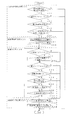
図3は実施の形態1における制御装置40が行う高圧抑制制御に係るフローチャートを表す図である。制御装置40は、前述したように、制御開始判断処理部40a、制御開始時処理部40b、制御中処理部40c及び制御終了時処理部40dを有している。図3に基づいて各部が行う処理について説明する。
FIG. 3 is a diagram illustrating a flowchart relating to high-pressure suppression control performed by the
制御開始判断処理部40aは高圧抑制制御を開始するか否かの開始条件判断処理を行う(S10)。本実施の形態では、開始判断において不可欠となる、制御有効時の運転モード、高圧上昇判断をするための物理的なパラメータの値、圧縮機11の駆動周波数及びバイパス回路用開閉弁21の状態の4項目に基づいて判断を行う。
The control start
まず、運転モードについて、熱交換容量を大きく変化させることができる熱源側熱交換器15が凝縮器として機能する場合は上記のような問題が発生しないことから、暖房運転又は暖房主体運転で運転しているかどうかを判断する(S11)。次に、高圧圧力上昇現象が発生しているかどうかの判断を行う。本実施の形態では、高圧圧力上昇現象に係る判断をするための物理的パラメータは、圧力センサ61から送信される信号に基づいて判断した高圧圧力PSとする。圧力センサ61からの信号に基づいて判断した高圧圧力PSの値が、あらかじめ設定した閾値P1よりも大きいかどうかを判断する(S12)。閾値P1よりも大きいと判断すると、前述した高圧圧力上昇現象が発生したものとする。
First, regarding the operation mode, when the heat source
図4は高圧抑制制御における閾値の設定条件を表す図である。ここで、高圧圧力PSの過度の上昇は、空気調和装置100(熱源側ユニット10)の故障原因となるため、設計においてその上限(高圧設計圧力)が定められる。そして、高圧設計圧力を越えるような圧力では、制御装置40は、空気調和装置100(熱源側ユニット10)を保護するための制御を行う。高圧抑制制御は、それより小さい圧力において処理を行えばよいので、閾値P1は、高圧設計圧力よりも下方にマージンを設けた値に設定するようにする。
FIG. 4 is a diagram illustrating threshold setting conditions in high-pressure suppression control. Here, an excessive increase in the high-pressure pressure PS causes a failure of the air conditioner 100 (heat source side unit 10), so an upper limit (high-pressure design pressure) is set in the design. And the
また、圧縮機11が最低駆動周波数で駆動しているかどうかを判断する(S15)。これは、圧縮機11が最低駆動周波数で駆動を行っても、なお、負荷に対して多くの冷媒が流れて能力過多となってしまう場合において高圧抑制制御を行うようにするためである。最低駆動周波数に基づいて判断を行うことは、エネルギ効率の面からは都合がよい。ただ、必ずしも最低駆動周波数に限定するものではなく、上方にマージンを持たせるようにしてもよい。ここで、高圧抑制制御は強制的に負荷側ユニット50に供給する能力(冷媒量)を抑えるものである。マージンを持たせすぎると、最もエネルギ消費が大きい圧縮機11を、供給する能力に対して過剰に駆動させてしまうことがあるため、注意する必要がある。さらに、バイパス用開閉弁22が開放された状態は、既に高圧抑制制御が開始されているので、バイパス用開閉弁22が閉じられた状態であるかどうかを判断し(S16)、閉じられた状態であると判断すると、制御開始時処理部40bによる制御開始時処理に移行させる。
Further, it is determined whether or not the compressor 11 is driven at the lowest drive frequency (S15). This is because, even when the compressor 11 is driven at the minimum drive frequency, the high pressure suppression control is performed when a large amount of refrigerant flows to the load and the capacity becomes excessive. The determination based on the minimum driving frequency is convenient from the viewpoint of energy efficiency. However, it is not necessarily limited to the minimum drive frequency, and a margin may be provided above. Here, the high pressure suppression control suppresses the ability (refrigerant amount) supplied to the load side unit 50 forcibly. If the margin is too large, the compressor 11 that consumes the largest amount of energy may be excessively driven with respect to the supply capability, so care must be taken. Furthermore, since the high pressure suppression control has already been started when the bypass on-off
制御開始時処理部40bは、制御開始判断処理部40aが高圧抑制制御を行うものと判断すると、バイパス用開閉弁22−バイパス用絞り装置23−バイパス管21−熱源側熱交換器15bを通過して圧縮機11の吸入側に至るバイパス回路を形成する制御開始時処理を行う(S20)。まず、熱源側開閉弁14bを閉止させる処理を行う(S21)。次にバイパス用開閉弁22を開放させる処理を行う(S22)。バイパス用開閉弁22を先に開放すると、熱源側開閉弁14bを通過している液冷媒とバイパス管21を通過したガス冷媒とが入り混じり、冷媒回路の流れを乱すため、熱源側開閉弁14bを閉止させてから、バイパス用開閉弁22を開放し、バイパスに冷媒を通過させる必要がある。ここで、前述したように選定した熱源側熱交換器15によっては、閉止させる熱源側開閉弁14は、熱源側開閉弁14bでなく、熱源側開閉弁14a又は14cになる場合もある。
When the control start
制御中処理部40cは、制御開始時処理部40bにより制御開始時処理が行われると高圧抑制制御中処理を行う(S30)。高圧抑制制御中処理では、開度調整制御処理及び制御終了判断処理を行う。まず、バイパス用絞り装置23の開度調整制御処理については、圧力センサ61からの信号に基づいて判断した高圧側圧力PSが閾値P1以上であると判断すると(S31)、バイパス用絞り装置23の開度を変更して大きくさせる(開く)処理を行い、バイパスに分流する冷媒の量を増やす(S32)。ここで、バイパス用絞り装置23の開度について説明する。制御開始処理時にバイパス用開閉弁22を開放させた際のバイパス用絞り装置23の初期開度はあらかじめ定めておく。この初期開度については、最低周波数において圧縮機11が供給する能力などのパラメータに基づいて、目標とする高圧圧力PSを閾値P2の圧力以下にするため、バイパスに流すべき冷媒量より決定する。また、バイパス用絞り装置23の開度変更幅については、あらかじめ任意に設定してもよい。本実施の形態では、圧力を低下させるために急激に多くの冷媒を分流させるのではなく、空気調和装置100の定常運転時における冷凍サイクルのバランスが維持できるように、10%〜20%増し程度の変更を行うようにする。ここで、閾値P2は、図4に示しているように、暖房運転、暖房主体運転時において、凝縮器として機能する負荷側熱交換器52aにおいて目標とする凝縮温度に近い温度における高圧圧力PSとなるように設定する。
When the control start
次に行う制御終了判断処理は、高圧抑制制御を行わなくてもよい物理的パラメータの値、圧縮機11の駆動周波数、運転モード及び圧縮機11の状態の4項目に基づいて判断する。本実施の形態では、判断のための物理的パラメータは制御開始判断と同様に高圧側圧力PSを用いる。圧力センサ61からの信号に基づいて、高圧側の圧力PSが閾値P2以下であるかどうかを判断する(S33)。
The control end determination process to be performed next is determined based on four items of physical parameter values that do not require high-pressure suppression control, the drive frequency of the compressor 11, the operation mode, and the state of the compressor 11. In the present embodiment, the physical parameter for determination uses the high-pressure side pressure PS as in the control start determination. Based on the signal from the
また、制御装置40は、各種センサからの信号に基づいて、負荷側ユニット10が要求する負荷を判断し、インバータ回路により圧縮機11の駆動周波数を変更し、負荷に合わせた能力供給を行う。そこで、例えば暖房運転を行う負荷側ユニット50が増えるなどにより、閾値F1以上の駆動周波数で圧縮機11を駆動させているかどうかを判断する(S34)。ここで、図4に示すように、例えば閾値F1としては、冷媒を分流しなかったときに最低駆動周波数により吐出する冷媒量を、冷媒を分流したときに熱源側ユニット50側に供給することができる圧縮機11の駆動周波数を設定する。つまり、S34においては圧縮機11が、最低駆動周波数で吐出する冷媒量を越える冷媒量を負荷側ユニット50に供給しているかどうかを判断することになる。
Moreover, the
また、負荷側熱交換器52が凝縮器ではなく蒸発器として機能する冷房運転又は冷房主体運転で運転しているかどうかを判断する(S35)。そして、圧縮機11が停止しているかどうかを判断する(S36)。制御中処理部40cは、S33〜S36の判断のうち、1つでも条件を満たしていると判断すると、制御終了時処理部40dによる制御終了時処理に移行させる。一方、すべての条件を満たしていないと判断すると、所定の時間待機した後(S37)、S31に戻って開度調整制御処理及び制御終了判断処理を行う。所定の時間については、例えば、制御中処理部40c(制御装置40)が記憶手段45に記憶された制御プログラムなどにより、その処理を行っている場合は、制御ソフトウェアにおける次のサンプリングまでの時間となる。
Further, it is determined whether or not the load side heat exchanger 52 is operated in a cooling operation or a cooling main operation that functions as an evaporator instead of a condenser (S35). And it is judged whether the compressor 11 has stopped (S36). If the in-
ここで、制御中処理部40cが行う2つの制御処理は、制御プロセスとして、それぞれ互いに干渉しない処理であるため、どちらの処理を先に行ってもよいと考えられる。ただ、制御終了判断処理を開度調整制御処理より先に処理してしまうと、制御開始時処理部40bが処理を行った後、高圧抑制制御を行う前に制御終了を判断する可能性があることから、開度調整制御処理、制御終了判断処理の順に行うことが望ましい。
Here, the two control processes performed by the in-
制御終了時処理部40dは、制御中処理部40cが制御終了判断処理において制御終了と判断すると、冷媒がバイパスを通過しないようにし、制御開始時処理前における冷媒の流れに戻すための制御終了時処理を行う(S40)。まず、バイパス用開閉弁22を閉止させるための処理を行う(S41)。次に、熱源側開閉弁14bを開放させるための処理を行う(S42)。ここで、熱源側開閉弁14bを先に開放させると、熱源側開閉弁14bを流れてくる液冷媒とバイパス管21を通過したガス冷媒とが入り混じり、冷媒回路の流れを乱すため、バイパス用開閉弁22を先に閉止させ、バイパスを通過する冷媒の流れを遮断した後、熱源側開閉弁14bを開放させるようにする。
When the in-
以上のように、実施の形態1の空気調和装置100によれば、暖房運転、暖房主体運転時において、圧縮機11が最低駆動周波数で駆動しているときに、圧力センサ61からの信号に基づいて、高圧圧力PSがあらかじめ定めた閾値P1以上の圧力になったものと制御装置40が判断すると、バイパス用開閉弁22を開放して、バイパス管21によるバイパスに冷媒の一部を分流して負荷側ユニット50側に流れる冷媒量を少なくするようにしたので、熱源側ユニット10側から、負荷側熱交換器52の熱交換容量に合った能力(冷媒量)を供給することができ、高圧圧力上昇現象を抑え、過熱による圧縮機11の温度上昇、異常停止などを防止することができる。また、圧縮機11、負荷側ユニット50における運転の開始、停止回数を少なくするなどにより、例えば、COP(Coefficient of Performance :エネルギ消費効率)、APF(Annual Performance Factor:通年エネルギ消費効率)などを改善し、省エネルギを図ることができる。夏季でも暖房運転を行うことがあり、負荷側熱交換器52の熱交換容量が小さいことがある、冷暖混在運転が可能な空気調和装置100において、圧力上昇現象が発生する可能性が高いので、特に上記の効果を発揮することができる。
As described above, according to the
図9は、制御により変移するモリエル線図(p−h線図)を表す図である。実施の形態1で説明した方法を用いた場合、モリエル線図(p−h線図)は、図9の様に移行するが、この際、バイパス回路として利用している負荷側ユニット50の凝縮器(負荷側熱交換器52)による能力損失Qlossに対し、圧縮機11における入力低下幅(W1−W2)が大きい特性を持つ場合、上記の効果に加え、COP、APFは向上する。また、Qlossで発生した排熱を再利用すれば、COP、APFはさらに向上させることができる。 FIG. 9 is a diagram illustrating a Mollier diagram (ph diagram) which is changed by the control. When the method described in the first embodiment is used, the Mollier diagram (ph diagram) shifts as shown in FIG. 9. At this time, condensation of the load side unit 50 used as a bypass circuit is performed. When the input loss width (W1-W2) in the compressor 11 is large with respect to the capacity loss Qloss due to the compressor (load side heat exchanger 52), COP and APF are improved in addition to the above effects. Moreover, if the waste heat generated in Qloss is reused, COP and APF can be further improved.
さらに、冷暖分岐ユニット30は、複数の負荷側ユニット50a、50bを直列又は並列に切り換え可能に接続することができる。この場合において、複数の負荷側ユニット50a、50bが並列接続から直列接続に切り換えられ、冷媒の流れに対して上流側の負荷側ユニット50の負荷側熱交換器52のみが、例えば凝縮器として使用されることにより、高圧圧力が上昇した場合でも、バイパス用開閉弁22を開状態に制御し、冷媒を分流させるため、高圧の過上昇を効果的に抑制できる。特に、熱交換容量(負荷)が小さい負荷側熱交換器52aを有する負荷側ユニット50a(低能力ユニット)と、熱交換容量が大きい負荷側ユニット50b(高能力ユニット)とが混在する場合には、低能力ユニットが暖房運転、高能力ユニットが冷房運転を行う冷暖同時運転中に、高圧圧力が上昇する可能性がある。しかし、この実施の形態の空気調和装置では、制御装置40がバイパス用開閉弁22を開状態に制御して冷媒を分流させるため、高圧の過上昇を効果的に抑制できる。このとき、制御装置40が暖房運転している負荷側ユニット50を特定し、その熱交換能力、室内温度等から高圧の異常上昇のおそれがあることを圧力検出値によらず或いは圧力検出値を併用して判断することも可能である。
Furthermore, the cooling /
また、制御装置40が、圧力センサ61からの信号に基づいて圧力を判断するので、直接的に高圧圧力PSの上昇に基づいて高圧抑制制御の開始判断を行うことができる。そして、バイパスを通過した冷媒については、熱源側熱交換器15bを通過させて顕熱を除去して圧縮機11の吸入側に戻し、バイパス回路を構成するようにしたので、必要以上に温度が高い過熱蒸気の冷媒が、圧縮機11の吸入側に流入して、吸入側冷媒の温度を上昇させずにすむ。このため、さらに高圧圧力上昇現象を抑えることができる。このとき、バイパス管21の一端を複数の熱源側熱交換器15への配管のいずれかに連通させて冷媒の顕熱除去を行うようにしたので、専用の熱交換器を用いることなく、スペース及びコストの削減を図ることができる。さらに、制御装置40の指示に基づいて、高圧圧力PSの圧力状態に基づいて、バイパス用絞り装置23により分流する冷媒量を調整できるようにしたので、高圧圧力の上昇を効果的に抑えていくことができる。
Further, since the
実施の形態2.
図5は実施の形態2における制御装置40が行う高圧抑制制御に係るフローチャートを表す図である。ここで、空気調和装置100の装置構成は図1と同じであり、実施の形態1で説明を行っているため説明を省略する。実施の形態1では、制御開始判断処理部40aが、圧力センサ61からの信号により判断した高圧圧力PSに基づいて、開始条件判断処理を行った。
FIG. 5 is a diagram illustrating a flowchart relating to the high-pressure suppression control performed by the
前述したように、暖房運転、暖房主体運転時においては、熱源側熱交換器15が蒸発器の機能を果たすことになる。ここで、気温が高いほど空気が有する熱量が多くなるため、例えば夏季など外気温が20℃以上の場合には、熱源側熱交換器15において、冷媒と空気との熱交換がされやすくなる。この結果、外気温が高いときには冷媒の蒸発温度が上昇する傾向にある。これが圧縮機11の吸入側の圧力、高圧圧力PSの上昇につながり、高圧圧力上昇現象を引き起こす要因の一つとなる。そこで、本実施の形態では、制御開始判断処理部40aは、温度センサ62からの信号により判断した周辺温度Tに基づいて、高圧抑制制御を開始するか否かの開始条件判断処理を行うものとする。圧力上昇現象の要因が発生した段階で判断することで、例えば、系が安定する間に高圧設計圧力以上の圧力になってしまうような急激な圧力上昇になる前に、冷媒を分流し、高圧圧力PSを下げるなど、早期の対応を行うことができ、空気調和装置100(熱源側ユニット10)を保護するための制御を行うなどの事態を防ぐことができる。
As described above, during the heating operation and the heating-main operation, the heat source
図5において、図3と同じステップ番号を付しているものは、実施の形態1において説明した処理と同様の処理を行うので説明を省略する。前述したように、S11において、運転モードを判断した後、高圧圧力上昇現象の判断を行うが、本実施の形態では、この判断をするための物理的パラメータは、温度センサ62から送信される信号に基づいて判断した周辺温度Tとする。温度センサ62からの信号に基づいて判断した周辺温度Tの値が、あらかじめ設定した閾値T1よりも大きいかどうかを判断する(S13)。大きいと判断すると、前述した高圧圧力上昇現象発生の前触れがあるものとする。ここで、図4に示すように、閾値T1は夏季における外気温度に基づいて設定するものとする。
5 that have the same step numbers as those in FIG. 3 perform the same processes as those described in the first embodiment, and a description thereof will be omitted. As described above, after the operation mode is determined in S11, the high pressure increase phenomenon is determined. In this embodiment, the physical parameter for this determination is a signal transmitted from the
また、周辺温度Tだけで判断することも可能であるが、例えば、熱源側ユニット50における負荷と圧縮機11から供給する能力とのバランスがよければ高圧圧力上昇現象は発生しないため、周辺温度Tだけを判断条件とすると、高圧圧力上昇現象が発生しえないような運転状態であっても、高圧抑制制御を開始するものと判断してしまうことがある。そのため、他の判断条件(特に負荷側ユニット50の負荷に関する条件)を付することが望ましい。そこで、例えば暖房運転している負荷側ユニット50の台数を判断するなどの処理を行う。本実施の形態では、暖房運転している負荷側ユニット50の熱交換容量に関するパラメータの総和を算出し、その総和が閾値Q1以下であるかどうかを判断する(S14)。図4で示すように、閾値Q1は、例えば圧縮機11を最低駆動周波数で駆動したときに熱源側ユニット50に供給できる能力に基づいて設定するものとする。例えば、各負荷側ユニット50における熱交換容量に関するパラメータについては、そのデータを記憶装置41に記憶しておくようにする。制御開始判断処理部40aは、各熱源側ユニット50の負荷側制御装置54から送信された信号に基づいて、各熱源側ユニット50の運転状態を判断し、暖房運転を行っている熱源側ユニットの熱交換容量に関するパラメータのデータを記憶装置41から読み込み、総和を算出するようにする。
Although it is possible to make a determination based only on the ambient temperature T, for example, if the balance between the load in the heat source unit 50 and the ability supplied from the compressor 11 is good, the high pressure rise phenomenon does not occur. If only the determination condition is used, it may be determined that the high-pressure suppression control is started even in an operation state in which the high-pressure increase phenomenon cannot occur. Therefore, it is desirable to attach other determination conditions (particularly conditions relating to the load of the load side unit 50). Therefore, for example, processing such as determining the number of load-side units 50 in heating operation is performed. In the present embodiment, the sum of the parameters related to the heat exchange capacity of the load-side unit 50 that is in the heating operation is calculated, and it is determined whether the sum is equal to or less than the threshold value Q1 (S14). As shown in FIG. 4, the threshold value Q1 is set based on, for example, the ability that can be supplied to the heat source unit 50 when the compressor 11 is driven at the lowest drive frequency. For example, the parameter regarding the heat exchange capacity in each load side unit 50 is stored in the
そして、閾値Q1以下であると判断すれば、高圧圧力上昇現象が発生する可能性があるものとする。ここで、前述したように、実際に高圧圧力上昇現象が発生する前の段階で高圧抑制制御の開始を判断する。そのため、実施の形態1と同じ閾値P2とすると、バイパス用開閉弁22を開放した段階で既に閾値P2以下の条件を満たしていることがある。そこで、周辺温度Tに基づいて開始判断処理を行う場合、閾値P2については、実施の形態1の場合よりも低めに設定するとよい。
And if it is judged that it is below threshold value Q1, it will be assumed that a high pressure rise phenomenon may occur. Here, as described above, the start of the high-pressure suppression control is determined at a stage before the high-pressure rise actually occurs. Therefore, if the threshold value P2 is the same as that in the first embodiment, the condition below the threshold value P2 may already be satisfied when the bypass on-off
以上のように、実施の形態2の空気調和装置によれば、実施の形態1のように、高圧圧力上昇現象を抑え、過熱による圧縮機11の温度上昇、異常停止などの防止、省エネルギを図る。また、制御装置40が、温度センサ62からの信号に基づいて周辺温度Tを判断するようにしたので、高圧圧力上昇現象が発生しやすくなる夏季など外気温が高い場合にその要因が発生した段階で判断することができ、早期の対応を行うことができる。
As described above, according to the air conditioner of the second embodiment, as in the first embodiment, the high pressure increase phenomenon is suppressed, the temperature of the compressor 11 is increased due to overheating, the abnormal stop is prevented, and the energy is saved. Plan. Further, since the
実施の形態3.
図6は実施の形態3における制御装置40が行う高圧抑制制御に係るフローチャートを表す図である。本実施の形態においても、空気調和装置100の装置構成は図1と同じであるため説明を省略する。図6において、図3、図5と同じステップ番号を付しているものは、実施の形態1、2において説明した処理と同様の処理を行うので説明を省略する。本実施の形態は、圧力センサ61からの信号に基づいて判断した高圧圧力PSと、温度センサ62からの信号に基づいて判断した周辺温度Tとの両方に基づいて、制御開始判断処理部40aが開始条件判断処理を行うようにしたものである。高圧圧力PS及び周辺温度Tにより高圧抑制制御を行うか否かの判断材料を多くし、空気調和装置100の状態に応じた判断を行うことができる。
FIG. 6 is a diagram illustrating a flowchart relating to the high-pressure suppression control performed by the
実施の形態4.
図7は実施の形態4に係る空気調和装置100Aの構成図である。例えば、分流しようとする(単位時間あたりの)冷媒量があらかじめ決まっている場合には、バイパス絞り装置22による開度調整を必要とせずにすむ。そこで、本実施の形態では、バイパス絞り装置22の代わりに、一定量の冷媒を通過させるキャピラリチューブ24を用いるものとする。
FIG. 7 is a configuration diagram of an
図8は実施の形態4における制御装置40が行う高圧抑制制御に係るフローチャートを表す図である。図8において、図3とおなじステップ番号を付しているものは、実施の形態1において説明した処理と同様の処理を行うので説明を省略する。図8に示すように、制御装置40の制御中処理部40cが行う高圧抑制制御中処理において、前述した開度調整制御処理となるS31、S32の処理を行わなくてもよい。そのため、制御装置40における制御中処理部40cが行う処理負担を減らすことができる。
FIG. 8 is a diagram illustrating a flowchart relating to the high-pressure suppression control performed by the
上述した実施の形態では、冷暖混在運転が可能な空気調和装置への適用について説明したが、本発明は、冷暖房切換運転が可能な他の空気調和装置についても適用することができる。また、例えばヒートポンプ装置等、冷媒回路を構成する他の冷凍サイクル装置にも適用することができる。 In the embodiment described above, the application to the air conditioner capable of performing the cooling and heating mixed operation has been described. However, the present invention can also be applied to other air conditioner capable of performing the cooling and heating switching operation. Further, the present invention can be applied to other refrigeration cycle apparatuses that constitute a refrigerant circuit, such as a heat pump apparatus.
Claims (8)
負荷側絞り装置及び負荷側熱交換器を有する複数の負荷側ユニットと、
暖房運転を行う前記負荷側ユニットに気体の冷媒を供給し、冷房運転を行う前記負荷側ユニットに液体の冷媒を供給するための気液分離器を有する冷暖分岐ユニットと
を配管接続して冷媒回路を構成し、冷媒を循環させて運転を行う冷暖房混在運転可能な空気調和装置であって、
前記圧縮機が吐出した冷媒が分流するバイパスを形成するバイパス管と、
開閉により前記バイパス管への冷媒の分流を制御するバイパス用開閉弁と、
前記熱源側熱交換器を蒸発器とし、前記負荷側熱交換器の少なくとも1つが凝縮器として機能する運転を行う際、前記圧縮機の吐出側における冷媒圧力の異常上昇又は異常上昇のおそれがあるかどうかを判断し、異常上昇又は異常上昇のおそれがあると判断すると、前記バイパス用開閉弁を開放させて前記バイパス管に冷媒を分流をさせる処理を行う制御手段と、
を備え、
前記熱源側熱交換器は、複数の熱交換器を冷媒回路に対して並列に配管接続して構成しており、
前記バイパス管を通過した冷媒が、前記複数の熱交換器のうちのいずれかの熱交換器を通過し、顕熱が除去されて前記圧縮機の吸入側に戻るように、前記バイパス管の一端と、前記いずれかの熱交換器に通じる配管とを連通させることを特徴とする空気調和装置。A heat source side unit having a heat source side heat exchanger and a compressor;
A plurality of load side units having a load side expansion device and a load side heat exchanger;
A refrigerant circuit is connected by piping to a cooling / heating branch unit having a gas-liquid separator for supplying a gaseous refrigerant to the load-side unit performing heating operation and supplying a liquid refrigerant to the load-side unit performing cooling operation An air conditioning apparatus capable of air-conditioning mixed operation that operates by circulating a refrigerant,
A bypass pipe forming a bypass through which the refrigerant discharged from the compressor is diverted;
A bypass on-off valve that controls the flow of refrigerant to the bypass pipe by opening and closing;
When performing an operation in which the heat source side heat exchanger is an evaporator and at least one of the load side heat exchangers functions as a condenser, there is a risk of abnormal rise or abnormal rise in refrigerant pressure on the discharge side of the compressor Control means for performing a process of opening the bypass on-off valve and diverting the refrigerant to the bypass pipe when it is determined that there is a risk of abnormal increase or abnormal increase;
Equipped with a,
The heat source side heat exchanger is configured by connecting a plurality of heat exchangers in parallel to the refrigerant circuit,
One end of the bypass pipe so that the refrigerant that has passed through the bypass pipe passes through any one of the plurality of heat exchangers, and sensible heat is removed to return to the suction side of the compressor. When the air conditioning apparatus according to claim Rukoto communicates with a pipe leading to the one of the heat exchanger.
前記制御手段は、前記複数の負荷側ユニットが直列接続に切り換えられた場合に、前記バイパス用開閉弁を開状態に制御することを特徴とする請求項1に記載の空気調和装置。The cooling / heating branch unit is connected so that at least two of the plurality of load side units can be switched in series or in parallel,
2. The air conditioner according to claim 1, wherein the control unit controls the bypass on-off valve to be in an open state when the plurality of load-side units are switched to a serial connection.
前記制御手段は、前記低能力ユニットが暖房運転、前記高能力ユニットが冷房運転を行う冷暖同時運転時に、前記バイパス用開閉弁を開状態に制御することを特徴とする請求項1又は2に記載の空気調和装置。The plurality of load-side units are composed of a high-capacity unit and a low-capacity unit,
The said control means controls the said on-off valve for bypass to an open state at the time of the cooling / heating simultaneous operation in which the said low capacity unit performs heating operation, and the said high capacity unit performs cooling operation. Air conditioner.
前記制御手段は、前記異常上昇又は異常上昇のおそれがあるかどうかの判断に加え、前記圧縮機が所定の駆動周波数以下で駆動しているものと判断したときに前記バイパス用開閉弁を開放させて前記バイパス管に冷媒を分流をさせる処理を行うことを特徴とする請求項1〜5のいずれかに記載の空気調和装置。The compressor is a variable capacity compressor having an inverter circuit for changing a driving frequency,
The control means opens the bypass on-off valve when determining that the compressor is operating at a predetermined drive frequency or lower, in addition to determining whether there is a risk of abnormal increase or abnormal increase. air conditioning apparatus according to any one of claims 1 to 5, characterized in that performing the process of the diverts coolant to the bypass pipe Te.
前記制御手段は、前記圧縮機の吐出側における冷媒の圧力に基づいて、前記バイパス用絞り装置の開度を制御することを特徴とする請求項1〜6のいずれかに記載の空気調和装置。The bypass further includes a bypass throttle device for controlling the amount of the refrigerant to be diverted,
The air conditioner according to any one of claims 1 to 6 , wherein the control means controls an opening degree of the bypass throttling device based on a refrigerant pressure on a discharge side of the compressor.
Applications Claiming Priority (1)
| Application Number | Priority Date | Filing Date | Title |
|---|---|---|---|
| PCT/JP2007/066593 WO2009028043A1 (en) | 2007-08-28 | 2007-08-28 | Air conditioner |
Publications (2)
| Publication Number | Publication Date |
|---|---|
| JPWO2009028043A1 JPWO2009028043A1 (en) | 2010-11-25 |
| JP5106536B2 true JP5106536B2 (en) | 2012-12-26 |
Family
ID=40386787
Family Applications (1)
| Application Number | Title | Priority Date | Filing Date |
|---|---|---|---|
| JP2009529893A Active JP5106536B2 (en) | 2007-08-28 | 2007-08-28 | Air conditioner |
Country Status (6)
| Country | Link |
|---|---|
| US (1) | US20110023512A1 (en) |
| EP (1) | EP2182306B1 (en) |
| JP (1) | JP5106536B2 (en) |
| CN (1) | CN101790669B (en) |
| HK (1) | HK1142947A1 (en) |
| WO (1) | WO2009028043A1 (en) |
Families Citing this family (20)
| Publication number | Priority date | Publication date | Assignee | Title |
|---|---|---|---|---|
| US20100204838A1 (en) * | 2009-02-12 | 2010-08-12 | Liebert Corporation | Energy efficient air conditioning system and method utilizing variable capacity compressor and sensible heat ratio load matching |
| WO2011104870A1 (en) * | 2010-02-26 | 2011-09-01 | 株式会社 日立製作所 | Air conditioner and air-conditioning hot-water-supplying system |
| JP5171924B2 (en) * | 2010-10-29 | 2013-03-27 | 三菱電機株式会社 | Air conditioner |
| US9625187B2 (en) | 2010-12-15 | 2017-04-18 | Mitsubishi Electric Corporation | Combined air-conditioning and hot-water supply system |
| EP2829823B1 (en) | 2012-03-15 | 2019-07-17 | Mitsubishi Electric Corporation | Refrigeration cycle apparatus |
| JP5889745B2 (en) * | 2012-08-03 | 2016-03-22 | 日立アプライアンス株式会社 | Refrigeration cycle apparatus, and refrigeration apparatus and air conditioner equipped with the refrigeration cycle apparatus |
| JP5983401B2 (en) * | 2012-12-28 | 2016-08-31 | ダイキン工業株式会社 | Air conditioner |
| WO2014118952A1 (en) * | 2013-01-31 | 2014-08-07 | 三菱電機株式会社 | Refrigeration-cycle device and method for controlling refrigeration-cycle device |
| US9488384B2 (en) * | 2013-03-22 | 2016-11-08 | Carrier Corporation | Heat pump water module with condensing coil in water storage tank |
| JP5747968B2 (en) * | 2013-10-07 | 2015-07-15 | ダイキン工業株式会社 | Heat recovery type refrigeration system |
| CN104949297B (en) * | 2014-03-27 | 2018-02-16 | 珠海格力电器股份有限公司 | Air-conditioner set and its compress control method |
| WO2015174054A1 (en) * | 2014-05-12 | 2015-11-19 | パナソニックIpマネジメント株式会社 | Refrigeration cycle device |
| CN104776630B (en) * | 2015-04-28 | 2017-05-03 | 广东美的暖通设备有限公司 | Multi-split system |
| CN107356003B (en) | 2016-05-10 | 2021-04-20 | 比亚迪股份有限公司 | Heat pump air conditioning system and electric automobile |
| CN107351624B (en) * | 2016-05-10 | 2020-08-25 | 比亚迪股份有限公司 | Heat pump air conditioning system and electric automobile |
| JP6721546B2 (en) * | 2017-07-21 | 2020-07-15 | ダイキン工業株式会社 | Refrigeration equipment |
| AU2018342809B2 (en) * | 2017-09-29 | 2020-07-09 | Daikin Industries, Ltd. | Air-conditioning system |
| US10941965B2 (en) * | 2018-05-11 | 2021-03-09 | Mitsubishi Electric Us, Inc. | System and method for providing supplemental heat to a refrigerant in an air-conditioner |
| CN108826419A (en) * | 2018-08-16 | 2018-11-16 | 爱能森(深圳)高端智能装备有限公司 | A kind of heat pump system, heating system and changes in temperature co-feeding system |
| US11933527B2 (en) * | 2020-02-27 | 2024-03-19 | Heatcraft Refrigeration Products Llc | Cooling system with oil return to accumulator |
Citations (5)
| Publication number | Priority date | Publication date | Assignee | Title |
|---|---|---|---|---|
| JPH0599519A (en) * | 1991-10-03 | 1993-04-20 | Mitsubishi Heavy Ind Ltd | Heat pump type air conditioner |
| JP2001330332A (en) * | 2000-05-22 | 2001-11-30 | Daikin Ind Ltd | Refrigerant circuit of air conditioner |
| JP2004085179A (en) * | 2002-08-22 | 2004-03-18 | Lg Electronics Inc | Multi-air conditioner and operation control method of outdoor fan |
| JP2006090683A (en) * | 2004-09-27 | 2006-04-06 | Samsung Electronics Co Ltd | Multiple room type air conditioner |
| JP2006300373A (en) * | 2005-04-18 | 2006-11-02 | Daikin Ind Ltd | Air conditioner |
Family Cites Families (12)
| Publication number | Priority date | Publication date | Assignee | Title |
|---|---|---|---|---|
| US3481152A (en) * | 1968-01-18 | 1969-12-02 | Frick Co | Condenser head pressure control system |
| JPH0799297B2 (en) * | 1986-06-25 | 1995-10-25 | 株式会社日立製作所 | Air conditioner |
| JP2664740B2 (en) * | 1988-09-30 | 1997-10-22 | 株式会社東芝 | Air conditioner |
| JP2909187B2 (en) * | 1990-10-26 | 1999-06-23 | 株式会社東芝 | Air conditioner |
| US5237833A (en) * | 1991-01-10 | 1993-08-24 | Mitsubishi Denki Kabushiki Kaisha | Air-conditioning system |
| JP3635665B2 (en) * | 1992-05-28 | 2005-04-06 | 三菱電機株式会社 | Air conditioner |
| JPH06341740A (en) * | 1993-05-28 | 1994-12-13 | Mitsubishi Heavy Ind Ltd | Operating method for heat pump type air conditioner |
| JPH11294886A (en) * | 1998-04-14 | 1999-10-29 | Hitachi Ltd | Air conditioner with heat storage tank |
| JP3744763B2 (en) * | 2000-02-24 | 2006-02-15 | 三洋電機株式会社 | Air conditioner |
| US6907745B2 (en) * | 2003-06-26 | 2005-06-21 | Carrier Corporation | Heat pump with improved performance in heating mode |
| US7475556B2 (en) * | 2004-03-15 | 2009-01-13 | Parker Hannifin Corporation | System and apparatus controlling a variable speed compressor system |
| KR101176482B1 (en) * | 2006-10-19 | 2012-08-22 | 엘지전자 주식회사 | Multi-air conditioner for heating and cooling operations at the same time |
-
2007
- 2007-08-28 CN CN2007801003927A patent/CN101790669B/en active Active
- 2007-08-28 WO PCT/JP2007/066593 patent/WO2009028043A1/en active Application Filing
- 2007-08-28 EP EP07806115.7A patent/EP2182306B1/en active Active
- 2007-08-28 US US12/674,036 patent/US20110023512A1/en not_active Abandoned
- 2007-08-28 JP JP2009529893A patent/JP5106536B2/en active Active
-
2010
- 2010-09-28 HK HK10109247.0A patent/HK1142947A1/en not_active IP Right Cessation
Patent Citations (5)
| Publication number | Priority date | Publication date | Assignee | Title |
|---|---|---|---|---|
| JPH0599519A (en) * | 1991-10-03 | 1993-04-20 | Mitsubishi Heavy Ind Ltd | Heat pump type air conditioner |
| JP2001330332A (en) * | 2000-05-22 | 2001-11-30 | Daikin Ind Ltd | Refrigerant circuit of air conditioner |
| JP2004085179A (en) * | 2002-08-22 | 2004-03-18 | Lg Electronics Inc | Multi-air conditioner and operation control method of outdoor fan |
| JP2006090683A (en) * | 2004-09-27 | 2006-04-06 | Samsung Electronics Co Ltd | Multiple room type air conditioner |
| JP2006300373A (en) * | 2005-04-18 | 2006-11-02 | Daikin Ind Ltd | Air conditioner |
Also Published As
| Publication number | Publication date |
|---|---|
| CN101790669A (en) | 2010-07-28 |
| HK1142947A1 (en) | 2010-12-17 |
| EP2182306A1 (en) | 2010-05-05 |
| EP2182306A4 (en) | 2016-02-17 |
| EP2182306B1 (en) | 2017-11-01 |
| US20110023512A1 (en) | 2011-02-03 |
| CN101790669B (en) | 2012-08-08 |
| JPWO2009028043A1 (en) | 2010-11-25 |
| WO2009028043A1 (en) | 2009-03-05 |
Similar Documents
| Publication | Publication Date | Title |
|---|---|---|
| JP5106536B2 (en) | Air conditioner | |
| JP5774225B2 (en) | Air conditioner | |
| JP5318099B2 (en) | Refrigeration cycle apparatus and control method thereof | |
| JP4200532B2 (en) | Refrigeration equipment | |
| JP5409715B2 (en) | Air conditioner | |
| US9080778B2 (en) | Air-conditioning hot-water supply combined system | |
| EP2902726B1 (en) | Combined air-conditioning and hot-water supply system | |
| US9863680B2 (en) | Heat pump apparatus | |
| JP2007240025A (en) | Refrigerating device | |
| JP5908183B1 (en) | Air conditioner | |
| JP2017161182A (en) | Heat pump device | |
| CN111133258B (en) | Air conditioner | |
| JP6948796B2 (en) | Refrigerant circuit system and control method | |
| JPWO2017130319A1 (en) | Refrigeration cycle equipment | |
| WO2020234994A1 (en) | Air conditioning device | |
| JP6695034B2 (en) | Heat pump device | |
| JP7444199B2 (en) | air conditioner | |
| WO2023032138A1 (en) | Refrigeration cycle device | |
| JP4548502B2 (en) | Refrigeration equipment | |
| WO2020202519A1 (en) | Refrigeration cycle device | |
| JP2023100176A (en) | air conditioner | |
| JP2017161085A (en) | Heat pump device | |
| JP2008020189A (en) | Refrigerating unit |
Legal Events
| Date | Code | Title | Description |
|---|---|---|---|
| A131 | Notification of reasons for refusal |
Free format text: JAPANESE INTERMEDIATE CODE: A131 Effective date: 20111220 |
|
| A521 | Written amendment |
Free format text: JAPANESE INTERMEDIATE CODE: A523 Effective date: 20120214 |
|
| TRDD | Decision of grant or rejection written | ||
| A01 | Written decision to grant a patent or to grant a registration (utility model) |
Free format text: JAPANESE INTERMEDIATE CODE: A01 Effective date: 20120904 |
|
| A01 | Written decision to grant a patent or to grant a registration (utility model) |
Free format text: JAPANESE INTERMEDIATE CODE: A01 |
|
| A61 | First payment of annual fees (during grant procedure) |
Free format text: JAPANESE INTERMEDIATE CODE: A61 Effective date: 20121002 |
|
| R150 | Certificate of patent or registration of utility model |
Ref document number: 5106536 Country of ref document: JP Free format text: JAPANESE INTERMEDIATE CODE: R150 Free format text: JAPANESE INTERMEDIATE CODE: R150 |
|
| FPAY | Renewal fee payment (event date is renewal date of database) |
Free format text: PAYMENT UNTIL: 20151012 Year of fee payment: 3 |
|
| R250 | Receipt of annual fees |
Free format text: JAPANESE INTERMEDIATE CODE: R250 |
|
| R250 | Receipt of annual fees |
Free format text: JAPANESE INTERMEDIATE CODE: R250 |
|
| R250 | Receipt of annual fees |
Free format text: JAPANESE INTERMEDIATE CODE: R250 |
|
| R250 | Receipt of annual fees |
Free format text: JAPANESE INTERMEDIATE CODE: R250 |
|
| R250 | Receipt of annual fees |
Free format text: JAPANESE INTERMEDIATE CODE: R250 |
|
| R250 | Receipt of annual fees |
Free format text: JAPANESE INTERMEDIATE CODE: R250 |
|
| R250 | Receipt of annual fees |
Free format text: JAPANESE INTERMEDIATE CODE: R250 |
|
| R250 | Receipt of annual fees |
Free format text: JAPANESE INTERMEDIATE CODE: R250 |