JP5103171B2 - Assembly method of hydraulic camshaft adjuster - Google Patents
Assembly method of hydraulic camshaft adjuster Download PDFInfo
- Publication number
- JP5103171B2 JP5103171B2 JP2007511979A JP2007511979A JP5103171B2 JP 5103171 B2 JP5103171 B2 JP 5103171B2 JP 2007511979 A JP2007511979 A JP 2007511979A JP 2007511979 A JP2007511979 A JP 2007511979A JP 5103171 B2 JP5103171 B2 JP 5103171B2
- Authority
- JP
- Japan
- Prior art keywords
- main body
- assembly
- pin
- blade
- peripheral portion
- Prior art date
- Legal status (The legal status is an assumption and is not a legal conclusion. Google has not performed a legal analysis and makes no representation as to the accuracy of the status listed.)
- Expired - Fee Related
Links
Images


Classifications
-
- F—MECHANICAL ENGINEERING; LIGHTING; HEATING; WEAPONS; BLASTING
- F01—MACHINES OR ENGINES IN GENERAL; ENGINE PLANTS IN GENERAL; STEAM ENGINES
- F01L—CYCLICALLY OPERATING VALVES FOR MACHINES OR ENGINES
- F01L1/00—Valve-gear or valve arrangements, e.g. lift-valve gear
- F01L1/34—Valve-gear or valve arrangements, e.g. lift-valve gear characterised by the provision of means for changing the timing of the valves without changing the duration of opening and without affecting the magnitude of the valve lift
- F01L1/344—Valve-gear or valve arrangements, e.g. lift-valve gear characterised by the provision of means for changing the timing of the valves without changing the duration of opening and without affecting the magnitude of the valve lift changing the angular relationship between crankshaft and camshaft, e.g. using helicoidal gear
- F01L1/3442—Valve-gear or valve arrangements, e.g. lift-valve gear characterised by the provision of means for changing the timing of the valves without changing the duration of opening and without affecting the magnitude of the valve lift changing the angular relationship between crankshaft and camshaft, e.g. using helicoidal gear using hydraulic chambers with variable volume to transmit the rotating force
- F01L2001/3445—Details relating to the hydraulic means for changing the angular relationship
- F01L2001/34453—Locking means between driving and driven members
- F01L2001/34469—Lock movement parallel to camshaft axis
Description
本発明は請求項1の前段に記載の油圧式カムシャフトアジャスタの組立方法に関する。 The present invention relates to a method for assembling a hydraulic camshaft adjuster according to the first stage of claim 1.
燃料消費量の低減、未処理排気ガス放出の低減、そして出力とトルクを増加するため、火花点火式エンジンにおいてカムシャフトアジャスタを設けることが知られている。カムシャフトアジャスタはクランクシャフトに対するカムシャフトの相対的な位相位置を変化させる。今のところ、作動チャンバーを有する油圧ブレード型のアジャスタが広く使用されている。その調整は、制御弁を経由してエンジンの油圧回路からブレードユニットへ油を流入させることにより行なわれる。該制御弁は電磁装置により開閉される。 It is known to provide a camshaft adjuster in a spark ignition engine to reduce fuel consumption, reduce raw exhaust emissions, and increase power and torque. The camshaft adjuster changes the relative phase position of the camshaft with respect to the crankshaft. At present, hydraulic blade type adjusters having working chambers are widely used. The adjustment is performed by flowing oil from the engine hydraulic circuit to the blade unit via the control valve. The control valve is opened and closed by an electromagnetic device.
特許文献1は、内燃機関のクランクシャフトに対するカムシャフトの回転角度を調整する一般的なカムシャフトアジャスタを開示している。該カムシャフトアジャスタは、回転方向に対し駆動輪に固定接続される本体外周部、及び回転方向に対しカムシャフトに固定接続される本体内周部を有し、本体外周部は少なくとも一つの油圧チャンバーを有し、本体内周部は該油圧チャンバーを二つの作動チャンバーに分割する少なくとも一つの揺動ブレードを有する。該揺動ブレードは後方ストッパと前方ストッパの間を制御された油圧により移動させることが可能であり、ストッパのうちの一つにおいて、油圧で解除できロックの目的でロック溝/穴に係合する、ばねで負荷されたロックピンを用いてロック可能な基本位置を有する。該ロックピンは油圧が存在しない場合に、カムシャフトアジャスタの望ましくない動きを防止する。これらのロックピンは、ロック溝内に公差の集積から生じてロックの確実な機能に必要なロックの遊びを有する。ロックの遊びの限度値は、下限では確実なロック及び解除機能に関係し、上限では騒音の放出に関係する。騒音の放出は一方では揺動ブレードと後方ストッパ又は前方ストッパとの間の、そして他方ではロックピンとロック溝との間の減衰されない衝突を通じて発生する。静粛なエンジン及び確実に動作するロックを得る目的は、一般にロックの遊びの厳しい公差によって達成される。しかしながら、この厳しい公差にはロックの遊びを調整するための技術的な限界があり、ロックの遊びを連続的に測定することによって調整作業を監視することは非常に費用を要する。 Patent Document 1 discloses a general camshaft adjuster that adjusts the rotation angle of a camshaft with respect to a crankshaft of an internal combustion engine. The camshaft adjuster has a main body outer peripheral portion fixedly connected to the drive wheel in the rotational direction and a main body inner peripheral portion fixedly connected to the camshaft in the rotational direction, and the main body outer peripheral portion is at least one hydraulic chamber. The main body inner periphery has at least one oscillating blade that divides the hydraulic chamber into two working chambers. The oscillating blade can be moved between the rear stopper and the front stopper by controlled hydraulic pressure, and can be released by hydraulic pressure at one of the stoppers and engages the lock groove / hole for the purpose of locking. It has a basic position that can be locked using a spring-loaded lock pin. The lock pin prevents unwanted movement of the camshaft adjuster when hydraulic pressure is not present. These lock pins have the lock play required for reliable functioning of the lock resulting from the accumulation of tolerances in the lock groove. The limit value of the play of the lock is related to a reliable lock and release function at the lower limit and to noise emission at the upper limit. The emission of noise occurs on the one hand through an undamped collision between the oscillating blade and the rear or front stopper and on the other hand between the lock pin and the lock groove. The goal of obtaining a quiet engine and a reliably operating lock is generally achieved by tight tolerances in lock play. However, this tight tolerance has technical limitations for adjusting the lock play, and monitoring the adjustment operation by continuously measuring the lock play is very expensive.
本発明は、最小限の遊びを有し、調整プロセスを省略し、確実に組立てでき、費用効率の高い生産ができる油圧式カムシャフトアジャスタの組立方法を提供することにある。 The present invention has a minimal play, skip adjustment process, can be reliably assembled to provide a method of assembling a hydraulic camshaft adjuster can cost-effective production.
この目的は請求項1に記載された構成によって達成される。 This object is achieved by the configuration described in claim 1.
本発明によるカムシャフトアジャスタの実質的な利点は、ピンとロック用の凹部間のロックの遊びを調整するための調整装置が、カムシャフトアジャスタの組立て用には必要ないということである。最小限の遊びもまた確実に生み出すことができる。凹部の形状は目的に応じて設計することが可能である。該形状は生産容易化のために穴として構成されてもよい。凹部の形状は、半径方向の公差が大きい場合に同じロックの遊びを設けるため、ベースストッパのストップ・エッジ及び組立てストッパが、カムシャフトアジャスタの回転軸に対して半径方向に向いているような方法で設計されてもよい。凹部の形状は品質保証用の簡単な検査用ゲージを使用するために、双方のストップ・エッジが互いに平行で、場合によってはカムシャフトアジャスタの回転軸に対して半径方向に走る仮想の線とも平行であるとよい。 A substantial advantage of the camshaft adjuster according to the invention is that an adjustment device for adjusting the play of the lock between the pin and the locking recess is not necessary for the assembly of the camshaft adjuster. Minimal play can also be produced reliably. The shape of the recess can be designed according to the purpose. The shape may be configured as a hole for ease of production. The shape of the recess is such that the stop edge of the base stopper and the assembly stopper are oriented radially with respect to the rotation axis of the camshaft adjuster in order to provide the same locking play when the radial tolerance is large It may be designed with. The shape of the recess is such that both stop edges are parallel to each other, and in some cases parallel to an imaginary line running radially to the rotation axis of the camshaft adjuster, in order to use a simple inspection gauge for quality assurance. It is good to be.
本発明の更なる改良及び利点は他の従属項及び記述から明らかとなる。 Further improvements and advantages of the invention will become apparent from the other dependent claims and the description.
以下、図面を用いて、本発明の二つの例示的な実施形態を説明する。 Hereinafter, two exemplary embodiments of the present invention will be described with reference to the drawings.
図1〜6は本発明によるカムシャフトアジャスタの製造を示す。 1-6 illustrate the manufacture of a camshaft adjuster according to the present invention.
単純化のために同じ参照番号が図中の相当する構成部品に用いられる。更に、同一の構成部品に対しては図中の例として各場合に一つの要素のみが示される。 For simplicity, the same reference numerals are used for corresponding components in the figures. Furthermore, for the same component, only one element is shown in each case as an example in the figure.
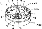
図1〜10は内燃機関のクランクシャフト(ここに図示せず)に対してカムシャフト(同様に図示せず)を調整するための油圧式カムシャフトアジャスタ1を示す。図1によれば、カムシャフトアジャスタ1は調整のため互いに対して回転可能な二つの伝達部品(2、3)を有し、本体内周部2は回転方向に固定された形でカムシャフトに固定され、本体外周部3はカムシャフトに対して回転可能に取り付けられる。伝達部品(2、3)は第一カバー4(図2)と第二カバー5(図5)の間に配置される。本体外周部3は駆動輪として設計された第一カバー4に回転方向に固定された形で固定され、駆動輪4はその外周に該駆動輪4と一体的に形成された、又は該駆動輪4と固定接続された別個部材である歯車6を有し、カムシャフトはその歯車6を介して内燃機関のクランクシャフトにより駆動される。この代替として、歯車6はまた本体外周部3に直接固定されてもよい。ここで示され、議論されている歯車によるギア駆動の代わりに、例えばタイミングベルト駆動あるいはチェーン駆動のような他の駆動接続であっても良い。
1 to 10 show a hydraulic camshaft adjuster 1 for adjusting a camshaft (also not shown) relative to a crankshaft (not shown here) of an internal combustion engine. According to FIG. 1, the camshaft adjuster 1 has two transmission parts (2, 3) that can rotate with respect to each other for adjustment, and the inner
図1によれば、カムシャフトを囲むスリーブ形の本体外周部3は、締付けねじを受けるための穴8を持つ内側に突き出たブレード7、7.1を有する。回転方向に固定された方法でカムシャフトに取り付けられる本体内周部2は外側に突き出た対応ブレード9、9.1を有する。本体外周部3のブレード7及び本体内周部2の対応ブレード9の双方とも、それらの外周に少なくとも一つのシール10、11を有する。本体内周部2及び本体外周部3は二つのカバー4、5と共に、特定の対応ブレード9、9.1により二つの作動チャンバー12a及び12bに分割されることが可能な、少なくとも一つの油圧媒体チャンバー12を形成し、作動チャンバー12bの隙間(図3)は例示されているカムシャフトアジャスタ1の位置においてのみ見ることができる。
According to FIG. 1, the sleeve-shaped
クランクシャフトの駆動トルクをカムシャフトに伝達可能にするため、既述したようにカムシャフトアジャスタ1の本体内周部2は回転方向に固定された方法でカムシャフトに接続される。駆動トルクは本体外周部3によってカムシャフトアジャスタ1へと導入され、そして作動チャンバー12a、12bを経由して本体内周部2に伝達される。カムシャフトアジャスタ1の本体外周部3とカムシャフトの間の位相位置は、作動チャンバー12a及び12bの油圧媒体の充填量を変えることにより調整可能である。制御弁(ここに図示せず)はカムシャフトアジャスタ1への油圧媒体の供給を制御し、従って位相位置もしくはその変化を制御する。
In order to make it possible to transmit the drive torque of the crankshaft to the camshaft, the main body inner
カムシャフトアジャスタ1は油圧により作動可能でピン13及び圧縮ばね14を備えたロック機構を有し、該ロック機構はピン13の軸方向の動きによって本体内周部2と本体外周部3の間のロック状態を生み出す。本体内周部2のブレード9.1に望ましくは配置され、その中へピン13がばね14と共に挿入されるピン穴は15により示され、ばね14はピン穴15が盲穴として設計された場合には、一方がピン穴15の底で、もう一方がピン13の端部側で支持され、そしてピン穴15がカバーで閉じられた通し穴として設計された場合には、一方がカバーで、もう一方がピン13で支持される。図3〜7によれば、カバーとして設計された駆動輪4は中にピン13がロックされた状態で係合する凹部16を有する。該凹部16は各々の場合ロック装置の構成によって二つのカバー4、5のうちの一つに形成され、凹部16は別個の部分としてカバー4、5に固定されるか、又はカバー4、5内に形成され、すなわちカバー4、5と一体に成形される。図10によれば、凹部16はピン13を受ける凹部16a及び解除用の溝として設計される凹部16bを有する。本体内周部2と本体外周部3の間の固定接続を解除する、すなわち取り外すために、ピンは特定の方向に対してばね力に反するように、解除用の溝16bを通じて油圧が作用され、ピンの移動が開始される。
The camshaft adjuster 1 has a lock mechanism that can be operated by hydraulic pressure and includes a
図8及び9はピン穴15’内に配置されたピン13’がカップの方式で設計され、その内部に少なくとも圧縮ばね14’を部分的に収容するロック装置の更なる改良を示す。凹部16の反対側にある端部では、ピン穴15’がリリース通路21を有する。
FIGS. 8 and 9 show a further improvement of the locking device in which the
図1〜6は油圧式カムシャフトアジャスタ1の組立品を示す。図1による上方からの斜視図は、本体内周部2が対応ブレード9.1の一つと共にロック位置17(図3,4参照)のストッパの所にあり、そして本体外周部3がブレード7.1の1つと共に同じ所にあることを示している。ブレード7.1と対応ブレード9.1が(ここでのみ)互いに当接し、ロック位置17は図3及び4にはっきりと見ることができ、一方で隙間18はブレード/対応ブレードの残りのペアの間に見られる。ベースストッパ17は圧力媒体の圧力が存在しない場合に、カムシャフトアジャスタ1の望ましくない動きを防止する。ピン13は圧縮ばね14と共に、本体内周部2の中に配置され盲穴として設計されているピン穴15内へと挿入され、最初に圧縮ばね14、続いてピン13が挿入されて、その結果圧縮ばね14は盲穴15の底に当接する。カムシャフトアジャスタ1は、ここではまだ解除位置にある。
1 to 6 show an assembly of the hydraulic camshaft adjuster 1. The perspective view from above according to FIG. 1 shows that the body
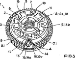
図2によれば、第一カバー4として設計された駆動輪は外周に配置されたその歯車6と共に、まだ解除位置にあるカムシャフトアジャスタ1上にその後に置かれている。 According to FIG. 2, the drive wheel designed as the first cover 4 is subsequently placed on the camshaft adjuster 1 which is still in the release position, with its gear 6 arranged on the outer periphery.
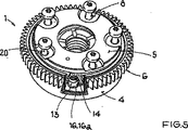
図3による下方からの斜視図は駆動輪4が置かれた後、該駆動輪4を時計回り又は反時計回りに回転することによりピン13が凹部16内へと案内され、カムシャフトアジャスタ1が今やロック状態にあることを示す。
In the perspective view from the lower side according to FIG. 3, after the driving wheel 4 is placed, the driving wheel 4 is rotated clockwise or counterclockwise so that the
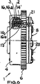
図4によれば、本体内周部2及び本体外周部3と共にパッケージ内にあるピン13は、今や駆動輪4に対して(反時計回りに)図10に見られる組立てストッパ19へ向けて回されており、圧縮ばね14のばね圧により保持されている。この位置においてカムシャフトアジャスタ1は最終的なロック位置にあり、第二カバー5は締付けねじ20が本体外周部3内に位置する穴8を通して挿入されることにより、図5に従って位置決めされることができる。図6はねじ締めされたカバー5及び、従って組立て状態の「固定」を示す。
According to FIG. 4, the
このロック装置の場合、最大のあり得るロックの遊びSは主に凹部16aにおける開口幅Wとピン13の直径Dとの差によって形成され、それにより構成部品の形状と位置の公差及び芯出し精度がロックの遊びに対して同様に影響を及ぼす可能性がある。組立てストッパ19は組立ての際、本体内周部2がロックピン13により組立てストッパ19に向かって回され、同時に本体内周部2及び本体外周部3が共通のストッパ、すなわちベースストッパ17の所に置かれるような方法で設計される。この位置から、これはロックの遊びSが主に二つのストッパ17と19の間の距離によってのみ形成されることを確実にする。
In the case of this locking device, the largest possible locking play S is mainly formed by the difference between the opening width W in the recess 16a and the diameter D of the
図7は図6による、しかし反転した位置におけるカムシャフトアジャスタを示し、ロック装置の領域がより良い理解のために切開して表わされている。既に上述のように、本体内周部2及び本体外周部3は共通のベースストッパ17の所に置かれ、ピン13は組立てストッパ19に対して当接している。本体内周部2は今やロックの遊びSによって反時計回りに回されることができ、それは本体内周部がベースストッパ17に対して当接する前に、カムシャフトアジャスタ1が既にロックされ得ることを意味する。
FIG. 7 shows the camshaft adjuster according to FIG. 6, but in the inverted position, with the area of the locking device being shown incised for better understanding. As already mentioned above, the inner
Claims (5)
前記組立ての際、前記本体内周部(2)の前記ブレード(9.1)及び前記本体外周部(3)の前記ブレード(7.1)が前記ベースストッパ位置(17)に位置づけられ、その後、前記ピン(13)が前記本体内周部(2)及び前記本体外周部(3)と一緒に前記カバー内の前記ロック用の凹部(16)に形成された組立てストッパ(19)に当接するように回され、この組立状態が、前記本体外周部(3)を前記カバーに固定することにより、固定されることを特徴とする組立方法。A main body inner periphery (2) having a blade (9, 9.1) connected to a camshaft in a fixed manner in a rotational direction, and provided rotatably with respect to the camshaft. .1) between the two covers (4, 5) and the blades (9, 9.1) and the main body outer peripheral portion (2) of the main body inner peripheral portion (2). 3) The blades (7, 7.1) are arranged so as to mesh with each other, and the pin (13) attached to the inner peripheral part (2) of the main body has the two covers (4, 5). Are engaged with each other by engaging with a locking recess (16) formed in one of the blades (9.1) and the outer peripheral portion (3) of the inner peripheral portion (2) of the main body. blade) (7.1) has a base stopper position (17) to be locked In the assembly method of the combustion engine of a hydraulic camshaft adjuster (1),
During the assembly, the blade (9.1) of the inner peripheral part (2) of the main body and the blade (7.1) of the outer peripheral part of the main body (3) are positioned at the base stopper position (17). The pin (13) contacts the assembly stopper (19) formed in the locking recess (16) in the cover together with the main body inner periphery (2) and the main body outer periphery (3). The assembly method is characterized in that the assembly state is fixed by fixing the outer peripheral portion (3) of the main body to the cover.
組立のための次のステップ、
a)前記本体内周部(2)のブレード(9.1)が前記ベースストッパ位置(17)に位置づけられ、そして前記本体外周部(3)のブレード(7.1)が前記ベースストッパ位置(17)に位置づけられるステップと、
b)前記ピン(13)及び圧縮ばね(14)が前記本体内周部(2)内に配置されたピン穴(15)内へ挿入されるステップと、
c)駆動輪として設計された第一カバー(4)が前記二つの本体(2、3)上に置かれるステップと、
d)前記ピン(13)が、前記駆動輪(4)を後方又は前方に回転させることにより前記ロック用の凹部(16)内へ挿入されるステップと、
e)前記本体内周部(2)及び前記本体外周部(3)と共に前記ピン(13)が、前記ロック用の凹部(16)内の前記組立てストッパ(19)に当接するように、前記駆動輪(4)に対して回されるステップと、
f)第二カバー(5)が前記二つの本体(2、3)上に置かれ、位置決めされるステップと、
g)前記第二カバー(5)が前記カムシャフトアジャスタ(1)にねじ締めされるステップと
によって特徴づけられる組立方法。Connected to the cam shaft is fixed to the rotating direction method, body peripheral portion having a blade (9,9.1) and (2), rotatably provided with respect to the cam shaft, the blades (7, 7 .1) between the two covers (4, 5) and the blades (9, 9.1) and the main body outer peripheral portion (2) of the main body inner peripheral portion (2). 3) The blades (7, 7.1) are arranged so as to mesh with each other, and the pin (13) attached to the inner peripheral part (2) of the main body has the two covers (4, 5). Are engaged with each other by engaging with a locking recess (16) formed in one of the blades (9.1) and the outer peripheral portion (3) of the inner peripheral portion (2) of the main body. blade) (7.1) has a base stopper position (17) to be locked In the assembly method of the combustion engine of a hydraulic camshaft adjuster (1),
The next step for assembly,
a) The blade (9.1) of the inner periphery (2) of the main body is positioned at the base stopper position (17), and the blade (7.1) of the outer periphery (3) of the main body is positioned at the base stopper position ( 17)
b) inserting the pin (13) and the compression spring (14) into a pin hole (15) disposed in the inner periphery (2) of the body;
c) a first cover (4) designed as a drive wheel is placed on the two bodies (2, 3);
d) the pin (13) being inserted into the locking recess (16) by rotating the drive wheel (4) backward or forward;
e) The drive so that the pin (13) together with the main body inner peripheral part (2) and the main body outer peripheral part (3) abuts the assembly stopper (19) in the locking recess (16). A step rotated relative to the wheel (4);
f) a second cover (5) being placed and positioned on the two bodies (2, 3);
g) An assembly method characterized by the step of screwing the second cover (5) onto the camshaft adjuster (1).
Applications Claiming Priority (3)
| Application Number | Priority Date | Filing Date | Title |
|---|---|---|---|
| DE102004022097.2 | 2004-05-05 | ||
| DE102004022097A DE102004022097A1 (en) | 2004-05-05 | 2004-05-05 | Hydraulic camshaft adjuster and method of mounting same |
| PCT/EP2005/004624 WO2005108752A1 (en) | 2004-05-05 | 2005-04-29 | Hydraulic camshaft adjuster and method for adjusting the same |
Publications (3)
| Publication Number | Publication Date |
|---|---|
| JP2007536463A JP2007536463A (en) | 2007-12-13 |
| JP2007536463A5 JP2007536463A5 (en) | 2011-04-21 |
| JP5103171B2 true JP5103171B2 (en) | 2012-12-19 |
Family
ID=34967242
Family Applications (1)
| Application Number | Title | Priority Date | Filing Date |
|---|---|---|---|
| JP2007511979A Expired - Fee Related JP5103171B2 (en) | 2004-05-05 | 2005-04-29 | Assembly method of hydraulic camshaft adjuster |
Country Status (4)
| Country | Link |
|---|---|
| US (1) | US7661397B2 (en) |
| JP (1) | JP5103171B2 (en) |
| DE (1) | DE102004022097A1 (en) |
| WO (1) | WO2005108752A1 (en) |
Families Citing this family (13)
| Publication number | Priority date | Publication date | Assignee | Title |
|---|---|---|---|---|
| DE102007011282A1 (en) | 2007-03-08 | 2008-09-11 | Schaeffler Kg | Device for adjusting the camshaft of an internal combustion engine |
| DE102008021315A1 (en) * | 2008-04-29 | 2009-11-05 | Schaeffler Kg | Device for adjusting the rotational position of a camshaft relative to a crankshaft of an internal combustion engine |
| DE102008028640A1 (en) | 2008-06-18 | 2009-12-24 | Gkn Sinter Metals Holding Gmbh | Hydraulic camshaft adjuster |
| DE102009020653A1 (en) | 2009-05-08 | 2010-11-18 | Daimler Ag | Phase adjuster, particularly valve impulse phase adjuster for assembly fixture, for adjustment of phase position of shaft, has assembly module, hydraulic adjustment unit and two cover units |
| EP2360357A1 (en) * | 2010-02-11 | 2011-08-24 | Delphi Technologies, Inc. | Camshaft phase shifter |
| JP5569458B2 (en) * | 2011-04-18 | 2014-08-13 | 株式会社デンソー | Valve timing adjustment device |
| DE102012209532A1 (en) | 2012-06-06 | 2013-12-12 | Schaeffler Technologies AG & Co. KG | Rotor for a hydraulic camshaft adjuster |
| DE102013207747A1 (en) * | 2013-04-29 | 2014-10-30 | Schaeffler Technologies Gmbh & Co. Kg | Hydraulic camshaft adjuster with partial recess on its camshaft flange surface |
| DE102014009091A1 (en) * | 2014-06-19 | 2015-12-24 | Hilite Germany Gmbh | Swivel motor adjuster for a camshaft |
| DE102016107986A1 (en) | 2015-11-04 | 2017-05-04 | Hilite Germany Gmbh | Hydraulic valve and connecting rod with a hydraulic valve |
| DE102016220943A1 (en) | 2016-10-25 | 2018-04-26 | Schaeffler Technologies AG & Co. KG | Camshaft adjuster with locking mechanism |
| US10458289B2 (en) * | 2017-03-16 | 2019-10-29 | Ford Global Technologies, Llc | System and method for a phase control apparatus of a cam timing system |
| CN108729971A (en) * | 2018-06-22 | 2018-11-02 | 博格华纳汽车零部件(宁波)有限公司 | Variable cam phase regulator |
Family Cites Families (11)
| Publication number | Priority date | Publication date | Assignee | Title |
|---|---|---|---|---|
| JP2000230511A (en) * | 1998-12-07 | 2000-08-22 | Mitsubishi Electric Corp | Vane type hydraulic actuator |
| JP2000179310A (en) | 1998-12-11 | 2000-06-27 | Toyota Motor Corp | Valve timing control device for internal combustion engine |
| DE10064222B4 (en) * | 1999-12-24 | 2006-02-09 | Aisin Seiki K.K., Kariya | Adjustable valve control system |
| JP4389383B2 (en) * | 1999-12-24 | 2009-12-24 | アイシン精機株式会社 | Valve timing control device |
| DE10213831A1 (en) * | 2001-03-28 | 2002-11-07 | Denso Corp | Variable valve timing device |
| JP3807314B2 (en) * | 2001-03-28 | 2006-08-09 | 株式会社デンソー | Valve timing adjustment device |
| JP4411814B2 (en) * | 2001-03-30 | 2010-02-10 | 株式会社デンソー | Valve timing adjustment device |
| JP3476786B2 (en) | 2001-04-20 | 2003-12-10 | 株式会社日立ユニシアオートモティブ | Valve timing control device for internal combustion engine |
| DE10150856B4 (en) | 2001-10-15 | 2005-08-11 | Ina-Schaeffler Kg | Device for changing the timing of gas exchange valves of an internal combustion engine, in particular rotary piston adjusting device for adjusting the rotational angle of a camshaft relative to a crankshaft |
| DE10253496B4 (en) * | 2001-11-21 | 2017-03-16 | Schaeffler Technologies AG & Co. KG | Method for operating a hydraulic camshaft adjuster s |
| JP4177197B2 (en) | 2003-08-08 | 2008-11-05 | 株式会社日立製作所 | Valve timing control device for internal combustion engine |
-
2004
- 2004-05-05 DE DE102004022097A patent/DE102004022097A1/en not_active Withdrawn
-
2005
- 2005-04-29 WO PCT/EP2005/004624 patent/WO2005108752A1/en active Application Filing
- 2005-04-29 JP JP2007511979A patent/JP5103171B2/en not_active Expired - Fee Related
-
2006
- 2006-11-03 US US11/592,730 patent/US7661397B2/en not_active Expired - Fee Related
Also Published As
| Publication number | Publication date |
|---|---|
| DE102004022097A1 (en) | 2005-12-08 |
| US20070095317A1 (en) | 2007-05-03 |
| JP2007536463A (en) | 2007-12-13 |
| WO2005108752A1 (en) | 2005-11-17 |
| US7661397B2 (en) | 2010-02-16 |
Similar Documents
| Publication | Publication Date | Title |
|---|---|---|
| JP5103171B2 (en) | Assembly method of hydraulic camshaft adjuster | |
| JP2007536463A5 (en) | ||
| JP5925172B2 (en) | Concentric cam with check valve in spool for phaser | |
| JP4161277B2 (en) | Valve timing control device | |
| JP4570977B2 (en) | Valve timing control device for internal combustion engine and assembly method thereof | |
| JP6350365B2 (en) | Valve timing adjusting device, lock jig used for manufacturing valve timing adjusting device, and method for manufacturing valve timing adjusting device | |
| US20050045130A1 (en) | Camshaft incorporating variable camshaft timing phaser rotor | |
| JP2005325758A (en) | Valve timing adjusting device | |
| JPH11153009A (en) | Valve timing adjusting device for internal combustion engine | |
| JP2005016482A (en) | Valve timing controlling device | |
| JP5360111B2 (en) | Valve timing adjustment device | |
| JP3385929B2 (en) | Valve timing control device for internal combustion engine | |
| JP5071408B2 (en) | Valve timing adjusting device and manufacturing method thereof | |
| JP5835261B2 (en) | Manufacturing apparatus and manufacturing method of valve timing adjusting device | |
| JP4626819B2 (en) | Valve timing control device | |
| JP5472215B2 (en) | Valve timing adjusting device and assembly method thereof | |
| JP4487957B2 (en) | Valve timing adjustment device | |
| US9500105B2 (en) | Camshaft adjuster | |
| US7204217B2 (en) | Hydraulic camshaft adjuster for a camshaft of an internal combustion engine | |
| US10954828B2 (en) | Variable camshaft phaser with magnetic locking cover bushing | |
| JP4304878B2 (en) | Valve timing adjustment device | |
| WO2017002558A1 (en) | Valve timing control device of internal combustion engine | |
| JP3873466B2 (en) | Valve timing control device | |
| JP3963210B2 (en) | Valve timing control device for internal combustion engine | |
| JP3991473B2 (en) | Valve timing control device |
Legal Events
| Date | Code | Title | Description |
|---|---|---|---|
| A621 | Written request for application examination |
Free format text: JAPANESE INTERMEDIATE CODE: A621 Effective date: 20080314 |
|
| A131 | Notification of reasons for refusal |
Free format text: JAPANESE INTERMEDIATE CODE: A131 Effective date: 20101027 |
|
| A601 | Written request for extension of time |
Free format text: JAPANESE INTERMEDIATE CODE: A601 Effective date: 20110127 |
|
| RD03 | Notification of appointment of power of attorney |
Free format text: JAPANESE INTERMEDIATE CODE: A7423 Effective date: 20110127 |
|
| A602 | Written permission of extension of time |
Free format text: JAPANESE INTERMEDIATE CODE: A602 Effective date: 20110203 |
|
| A524 | Written submission of copy of amendment under section 19 (pct) |
Free format text: JAPANESE INTERMEDIATE CODE: A524 Effective date: 20110228 |
|
| A02 | Decision of refusal |
Free format text: JAPANESE INTERMEDIATE CODE: A02 Effective date: 20110531 |
|
| A521 | Written amendment |
Free format text: JAPANESE INTERMEDIATE CODE: A523 Effective date: 20110930 |
|
| A911 | Transfer to examiner for re-examination before appeal (zenchi) |
Free format text: JAPANESE INTERMEDIATE CODE: A911 Effective date: 20111007 |
|
| A912 | Re-examination (zenchi) completed and case transferred to appeal board |
Free format text: JAPANESE INTERMEDIATE CODE: A912 Effective date: 20120127 |
|
| A01 | Written decision to grant a patent or to grant a registration (utility model) |
Free format text: JAPANESE INTERMEDIATE CODE: A01 |
|
| A61 | First payment of annual fees (during grant procedure) |
Free format text: JAPANESE INTERMEDIATE CODE: A61 Effective date: 20121001 |
|
| FPAY | Renewal fee payment (event date is renewal date of database) |
Free format text: PAYMENT UNTIL: 20151005 Year of fee payment: 3 |
|
| R150 | Certificate of patent or registration of utility model |
Free format text: JAPANESE INTERMEDIATE CODE: R150 |
|
| R250 | Receipt of annual fees |
Free format text: JAPANESE INTERMEDIATE CODE: R250 |
|
| R250 | Receipt of annual fees |
Free format text: JAPANESE INTERMEDIATE CODE: R250 |
|
| RD04 | Notification of resignation of power of attorney |
Free format text: JAPANESE INTERMEDIATE CODE: R3D04 |
|
| LAPS | Cancellation because of no payment of annual fees |