JP5102811B2 - Inner rotor type heat dissipation fan - Google Patents
Inner rotor type heat dissipation fan Download PDFInfo
- Publication number
- JP5102811B2 JP5102811B2 JP2009154282A JP2009154282A JP5102811B2 JP 5102811 B2 JP5102811 B2 JP 5102811B2 JP 2009154282 A JP2009154282 A JP 2009154282A JP 2009154282 A JP2009154282 A JP 2009154282A JP 5102811 B2 JP5102811 B2 JP 5102811B2
- Authority
- JP
- Japan
- Prior art keywords
- inner rotor
- seal casing
- rotor type
- frame
- fixed seat
- Prior art date
- Legal status (The legal status is an assumption and is not a legal conclusion. Google has not performed a legal analysis and makes no representation as to the accuracy of the status listed.)
- Active
Links
Images


Classifications
-
- H—ELECTRICITY
- H02—GENERATION; CONVERSION OR DISTRIBUTION OF ELECTRIC POWER
- H02K—DYNAMO-ELECTRIC MACHINES
- H02K9/00—Arrangements for cooling or ventilating
- H02K9/02—Arrangements for cooling or ventilating by ambient air flowing through the machine
- H02K9/04—Arrangements for cooling or ventilating by ambient air flowing through the machine having means for generating a flow of cooling medium
- H02K9/06—Arrangements for cooling or ventilating by ambient air flowing through the machine having means for generating a flow of cooling medium with fans or impellers driven by the machine shaft
-
- F—MECHANICAL ENGINEERING; LIGHTING; HEATING; WEAPONS; BLASTING
- F04—POSITIVE - DISPLACEMENT MACHINES FOR LIQUIDS; PUMPS FOR LIQUIDS OR ELASTIC FLUIDS
- F04D—NON-POSITIVE-DISPLACEMENT PUMPS
- F04D25/00—Pumping installations or systems
- F04D25/02—Units comprising pumps and their driving means
- F04D25/06—Units comprising pumps and their driving means the pump being electrically driven
- F04D25/0606—Units comprising pumps and their driving means the pump being electrically driven the electric motor being specially adapted for integration in the pump
-
- F—MECHANICAL ENGINEERING; LIGHTING; HEATING; WEAPONS; BLASTING
- F04—POSITIVE - DISPLACEMENT MACHINES FOR LIQUIDS; PUMPS FOR LIQUIDS OR ELASTIC FLUIDS
- F04D—NON-POSITIVE-DISPLACEMENT PUMPS
- F04D29/00—Details, component parts, or accessories
- F04D29/40—Casings; Connections of working fluid
- F04D29/52—Casings; Connections of working fluid for axial pumps
- F04D29/522—Casings; Connections of working fluid for axial pumps especially adapted for elastic fluid pumps
- F04D29/526—Details of the casing section radially opposing blade tips
-
- F—MECHANICAL ENGINEERING; LIGHTING; HEATING; WEAPONS; BLASTING
- F04—POSITIVE - DISPLACEMENT MACHINES FOR LIQUIDS; PUMPS FOR LIQUIDS OR ELASTIC FLUIDS
- F04D—NON-POSITIVE-DISPLACEMENT PUMPS
- F04D29/00—Details, component parts, or accessories
- F04D29/60—Mounting; Assembling; Disassembling
- F04D29/601—Mounting; Assembling; Disassembling specially adapted for elastic fluid pumps
-
- F—MECHANICAL ENGINEERING; LIGHTING; HEATING; WEAPONS; BLASTING
- F04—POSITIVE - DISPLACEMENT MACHINES FOR LIQUIDS; PUMPS FOR LIQUIDS OR ELASTIC FLUIDS
- F04D—NON-POSITIVE-DISPLACEMENT PUMPS
- F04D29/00—Details, component parts, or accessories
- F04D29/60—Mounting; Assembling; Disassembling
- F04D29/64—Mounting; Assembling; Disassembling of axial pumps
- F04D29/644—Mounting; Assembling; Disassembling of axial pumps especially adapted for elastic fluid pumps
- F04D29/646—Mounting or removal of fans
-
- H—ELECTRICITY
- H02—GENERATION; CONVERSION OR DISTRIBUTION OF ELECTRIC POWER
- H02K—DYNAMO-ELECTRIC MACHINES
- H02K7/00—Arrangements for handling mechanical energy structurally associated with dynamo-electric machines, e.g. structural association with mechanical driving motors or auxiliary dynamo-electric machines
- H02K7/14—Structural association with mechanical loads, e.g. with hand-held machine tools or fans
Description
本発明は、放熱ファンに関するもので、特に内ローター式モーターを利用して駆動する内ローター式放熱ファンに係るものである。 The present invention relates to a heat dissipating fan, and more particularly to an inner rotor heat dissipating fan that is driven using an inner rotor motor.
従来の放熱ファンの一般な構造として、外ローター式モーターを利用して回動するように駆動を行うものがある。この外ローター式モーターとしては、例えば中華民国新型公告第488497号「ファンの増圧導流装置」(特許文献1を参照)があり、そこにおいて、概略、ステータ組を利用してローターが回動して作動するのを駆動することができるようにとしている。 As a general structure of a conventional heat dissipating fan, there is one that drives to rotate using an outer rotor type motor. As this outer rotor type motor, for example, there is a new announcement of the Republic of China No. 488497 “Fan pressure booster device” (refer to Patent Document 1), in which the rotor is rotated using a stator assembly. It can be driven to operate.
また、従来の放熱ファンの構造として、例えば図8を参照すると、外ローター式モーターを利用して従来の放熱ファン70を駆動する構造が掲示されている。放熱ファン70にはフレーム71、ステータ72、回路板73およびローター74が含まれる。フレーム71の内側には軸管711が設けられ、軸管711の内に少なくとも一個の軸受け712が設けられる。ステータ72と回路板73は軸管711の外側の周面に嵌設され、回路板73はステータ72と電気的に接続される。ローター74には回動軸741とインペラー742が形成され、回動軸741の一端は軸管711の内まで伸び入れられて軸受け712と枢接するように形成される。インペラー742は回動軸741の他端に結合され、インペラー742にはステータ72に対応するように永久磁石743が設けられる。これにより、回路板73によってステータ72と永久磁石743との間に磁束鎖交の作用が生じるのを制御することにより、インペラー742が回動して作動するのを連動することができるため、一定の放熱の効果を達成することができるようにとしたものがある。
For example, referring to FIG. 8, as a structure of a conventional heat radiating fan, a structure for driving a conventional
上述した従来の放熱ファン70は主に外ローター式モーターを採用して駆動を行うものである。しかし、一般的に、外ローター式モーターは内ローター式モーターと比べて、回動の安定性が比較的劣るとともに、回転速度が比較的低いなどの問題点を有し、また現在では電子製品に関しては普遍的に高速度、功能の整合性と微小化などの方向に研究開発を行っているため、電子製品に要求される放熱の効能性も段々と高まる。そのため、上述した外ローター式モーターを利用して駆動を行う従来の放熱ファン70では一部分の電子製品における放熱の要求を充分に満足することができなかった。
The conventional
上述した従来の放熱ファン70を放熱の需要が高い電子製品に適用させるべく、関係業者においては例えば中華民国公開第200744290号「ファンおよびその内ローター式モーター」(特許文献2を参照)が研究開発されている。例えば図9を参照すると、内ローター式モーターで駆動を行う従来の放熱ファン80が掲示されており、放熱ファン80には框体81、ステータ構造82、ローター構造83、駆動装置84およびインペラー85が含まれる。框体81は第一框体811と第二框体812により組成される。ステータ構造82には磁気導引部材821が形成される。ローター83には回動軸831と磁性部材832が形成され、回動軸831は框体81の内部まで貫穿されることにより、磁性部材832は回動軸831に嵌設されるとともに、磁気導引部材821に対応するように形成される。駆動装置84は磁気導引部材821に電気的に接続される。インペラー85は回動軸831と連結するとともに、框体81の外部に位置するように形成される。これにより、駆動装置84によって磁気導引部材821の電流の方向を制御することができるため、磁性部材832と磁束鎖交の作用が生じてローター構造83とインペラー85が回動して作動するのを駆動することができるようにとしたものがある。
In order to apply the above-described conventional heat-dissipating
しかし、上述した従来の放熱ファン80は各種の電子製品に対して放熱を行おうとする時、放熱ファン80にはフレームの設計を有しないため、運転時においてインペラー85から生じる気流を上記電子製品に予定される発熱の部位まで有効に導引して集中させることができず、そのため、従来の放熱ファン80においては相変わらず放熱の効果がよくないなどの問題点があった。
However, when the above-described conventional
上述した従来の放熱ファン80におけるフレームを有しないことから生じる問題点を改善するべく、例えば図10を参照すると、内ローター式モーターを利用し、かつフレームを有する放熱ファン90を駆動する構造が掲示されている。放熱ファン90にはフレーム91、内ローター式モーター92、インペラー93および回路板94が含まれる。フレーム91にはプラスチック材料を利用して射出成形によってフレーム部911とモーターフレーム92が形成され、モーターフレーム912はフレーム部911の内側に位置するように形成される。内ローター式モーター92はモーターフレーム912の内部に結合され、内ローター式モーター92には回動軸921、磁性部材922とステータ923が含まれる。回動軸921の一端はモーターフレーム912の外部まで伸出するように形成され、磁性部材922は回動軸921に結合されてステータ923に位置合わせるように形成される。インペラー93は回動軸921の一端に結合されてモーターフレーム912の外部に位置するように形成される。回路板94はステータ923に電気的に接続される。これにより、内ローター式モーター92を利用してインペラー93が回動して作動するのを駆動することができるため、予定される放熱の作用を提供できるようにしていた。
In order to improve the problems caused by the absence of the frame in the above-described conventional
上記のような従来の放熱ファン70においては、回動の安定性が比較的劣るとともに、回転速度が比較的低いなどの問題点があった。また、上記のような従来の放熱ファン80においては、フレームの設計を有しないため、運転時においてインペラー85から生じる気流を電子製品に予定される発熱の部位まで有効に導引して集中させることができないため、放熱の効果がよくないなどの問題点があった。
The conventional
さらに、上記のような従来の放熱ファン90においては、放熱ファン90は主に射出成形の方式によってフレーム91を形成するため、フレーム91の設計を利用してインペラー93が運転時において生じる気流を導引して集中させることはできる。しかし、フレーム91のモーターフレーム912はプラスチックの材料を利用して射出成形によって作成されるため、回路板94によりステータ923と磁性部材922との間に磁束鎖交の作用が生じるのを制御する過程において、モーターフレーム912そのものは磁気封止の作用を提供することができず、そのため、磁束漏洩の現象が生じ易くなるとともに、電磁妨害の問題も生じ易くなるため、インペラー93の運転時の功能に影響を及ぼし、ひいては従来の放熱ファン90の放熱効果が低くなるという問題点があった。
Further, in the conventional
本発明はこのような問題点に鑑みて発明されたものであって、その主な目的とするところは、内ローター式モーターを利用して駆動を行うことにより、磁束漏洩の現象が生じるのを有効に防止することができるとともに、電磁妨害の問題が生じるのを抑えることができる内ローター式放熱ファンを提供しようとするものである。 The present invention was invented in view of such problems, and the main object of the present invention is to cause the phenomenon of magnetic flux leakage by driving using an inner rotor type motor. It is an object of the present invention to provide an inner rotor type heat dissipation fan that can be effectively prevented and can suppress the occurrence of electromagnetic interference problems.
上記目的を達成するために、本発明による内ローター式放熱ファンは、フレーム、シールケーシング、内ローター式モーター、インペラーおよび回路板を有する。フレームには框体と固定座が形成され、框体の両端にはそれぞれ風入口と風出口が形成される。風入口と風出口との間には気流通路が形成され、固定座と框体との間は複数個の連接部材によって互いに連接するように形成される。シールケーシングは磁気導引性材料により作成される中空框体からなり、シールケーシングの一端には結合部が形成され、結合部はフレームの固定座に結合される。内ローター式モーターはシールケーシングの内部に設置され、内ローター式モーターにはローターとステータが含まれる。ローターは回動自在にステータの内に収容され、ローターには回動軸と磁性部材が形成され、磁性部材は回動軸と結合してステータに位置合わせるように形成される。インペラーは回動軸と結合してシールケーシングの外部に位置するように形成される。回路板はステータと電気的に接続するように形成される。 In order to achieve the above object, an inner rotor radiating fan according to the present invention includes a frame, a seal casing, an inner rotor motor, an impeller, and a circuit board. A frame and a fixed seat are formed on the frame, and a wind inlet and a wind outlet are formed at both ends of the frame, respectively. An airflow passage is formed between the wind inlet and the wind outlet, and the fixed seat and the housing are formed to be connected to each other by a plurality of connecting members. The seal casing is formed of a hollow casing made of a magnetically conductive material. A coupling portion is formed at one end of the sealing casing, and the coupling portion is coupled to a fixed seat of the frame. The inner rotor type motor is installed inside the seal casing, and the inner rotor type motor includes a rotor and a stator. The rotor is rotatably accommodated in the stator, the rotor is formed with a rotating shaft and a magnetic member, and the magnetic member is formed so as to be coupled to the rotating shaft and aligned with the stator. The impeller is formed so as to be coupled to the rotating shaft and located outside the seal casing. The circuit board is formed to be electrically connected to the stator.
また、本発明による内ローター式放熱ファンは、シールケーシングの外周面に凹部が形成され、フレームの固定座はシールケーシングの外周面を被覆し、固定座の内周面に係止部が形成され、係止部とシールケーシングの凹部との間は互いに係止して結合するように形成することもできる。また、シールケーシングの内周面に凸部が形成され、ステータの外周面に位置決め溝が形成され、位置決め溝はシールケーシングの凸部を係止するように形成することもできる。また、フレームの固定座は内側の周壁に位置決め部を有するスリーブからなり、固定座の内部に位置決め部材とシールキャップが結合され、位置決め部材とシールキャップは互いに結合して位置決め部に当接するように形成され、回路板は位置決め部材とシールキャップとの間に設置され、位置決め部材により回路板とステータが隔離されるように形成することもできる。また、フレームの固定座は内側の周壁には当接部を有するスリーブからなり、シールケーシングの結合部は当接部に当接するように形成することもできる。また、シールケーシングの結合部には拡径部が形成されることにより、シールケーシングの外周壁には段部が形成され、フレームの固定座の内側の周壁には位置決め部が形成され、段部と位置決め部は互いに係止して結合するように形成することもできる。また、シールケーシングの拡径部の底部の縁端には複数個の突出フックが形成されることもできる。 Further, in the inner rotor radiating fan according to the present invention, a concave portion is formed on the outer peripheral surface of the seal casing, the fixed seat of the frame covers the outer peripheral surface of the seal casing, and a locking portion is formed on the inner peripheral surface of the fixed seat. The locking portion and the recessed portion of the seal casing may be formed so as to be locked and coupled to each other. Moreover, a convex part is formed in the inner peripheral surface of a seal casing, a positioning groove is formed in the outer peripheral surface of a stator, and a positioning groove can also be formed so that the convex part of a seal casing may be latched. Further, the fixed seat of the frame is composed of a sleeve having a positioning portion on the inner peripheral wall, and a positioning member and a seal cap are coupled to the inside of the fixed seat, and the positioning member and the seal cap are coupled to each other and come into contact with the positioning portion. The circuit board may be formed between the positioning member and the seal cap, and the circuit board and the stator may be isolated by the positioning member. Further, the fixed seat of the frame may be formed of a sleeve having a contact portion on the inner peripheral wall, and the joint portion of the seal casing may be formed to contact the contact portion. In addition, a diameter-enlarged portion is formed in the joint portion of the seal casing, so that a step portion is formed on the outer peripheral wall of the seal casing, and a positioning portion is formed on the inner peripheral wall of the fixed seat of the frame. The positioning part can also be formed so as to be locked and coupled to each other. Also, a plurality of protruding hooks can be formed at the edge of the bottom of the enlarged diameter portion of the seal casing.
本発明の請求項1の内ローター式放熱ファンによれば、内ローター式モーターを利用してローターとインペラーの回動の作動を安定化することができ、またフレームを合わせて利用して上記インペラーから生じる気流を有効に導引して集中させることができ、さらにシールケーシングによって磁気封止の作用を提供して磁束漏洩の現象が生じるのを避けることができるとともに、電磁妨害の問題が生じるのを抑えることができ、全体の放熱の効果をより一層高めることができる。
According to the inner rotor type heat radiating fan of
本発明の請求項2の内ローター式放熱ファンによれば、シールケーシングは固定座に対して任意に回動したりまたは脱落したりするのを確保することができるため、上記シールケーシングと上記固定座との間の結合の安定性を高めることができる。
According to the inner rotor radiating fan of
本発明の請求項3の内ローター式放熱ファンによれば、ステータがシールケーシングの内部において任意に回動するのを確保することができるため、組立の便利性を高めることができる。
According to the inner rotor type heat radiating fan of
本発明の請求項4、5の内ローター式放熱ファンによれば、ステータが作動時において生じる高熱から回路板の放熱効果に影響を及ぼしてしまうのを避けることができるため、上記回路板における各種の電子部材が損壊してしまうのを有効に防止することができる。
According to the inner rotor type heat radiating fan of
本発明の請求項6、7、8、9の内ローター式放熱ファンによれば、シールケーシングと固定座との間の結合の安定性をより一層高めることができる。 According to the inner rotor type heat dissipating fan of claims 6, 7, 8, and 9 of the present invention, the stability of the coupling between the seal casing and the fixed seat can be further enhanced.
本発明の請求項10の内ローター式放熱ファンによれば、同様にシールケーシングと固定座との間の結合の安定性をより一層高めることができる。
According to the inner rotor radiating fan of
本発明の請求項11の内ローター式放熱ファンによれば、回路板などの部材が脱落するのを有効に防止することができる。 According to the inner rotor type heat radiating fan of the eleventh aspect of the present invention, it is possible to effectively prevent the members such as the circuit board from falling off.
本発明の実施の形態について、以下、図面を参照して説明する。 Embodiments of the present invention will be described below with reference to the drawings.
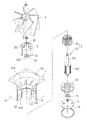
図1は本発明の第1実施形態の内ローター式放熱ファンによる分解斜視図、図2は本発明の第1実施形態の内ローター式放熱ファンによる組み立てられた状態の断面図である。図1、2を参照すると、本発明の第1の実施形態による内ローター式放熱ファンが掲示されており、内ローター式放熱ファンには主にフレーム1、シールケーシング2、内ローター式モーター3、インペラー4および回路板5が含まれる。
FIG. 1 is an exploded perspective view of an inner rotor type heat radiating fan according to the first embodiment of the present invention, and FIG. 2 is a cross-sectional view of the assembled state by the inner rotor type heat radiating fan of the first embodiment of the present invention. Referring to FIGS. 1 and 2, an inner rotor radiating fan according to a first embodiment of the present invention is posted. The inner rotor radiating fan mainly includes a
フレーム1は射出成形によって作成することができる。シールケーシング2はフレーム1の内側に結合される。内ローター式モーター3はシールケーシング2の内部に設置される。インペラー4は内ローター式モーター3と連結するように形成される。回路板5は内ローター式モーター3に電気的に接続される。これにより、回路板5を利用して内ローター式モーター3がインペラー4を連動して回動するように作動するのを制御することができ、またフレーム1によってインペラー4が回動時に生じる気流を導引して集中させることができ、さらにシールケーシング2を利用して磁気封止の作用を提供し、磁束漏洩の現象が生じるのを避けることができるとともに、電磁妨害の問題が生じるのを抑えることができる。
The
本発明の第1の実施形態におけるフレーム1には框体11と固定座12が形成される。框体11の両端にはそれぞれ風入口111と風出口112が形成され、風入口111と風出口112との間には気流通路113が形成される。固定座12は気流通路113内に形成され、かつ固定座12と框体11との間は複数個の連接部材13を利用して互いに連接することができる。それぞれの連接部材13は好ましくは框体11の風出口112に隣接するように形成され、そしてそれぞれの連接部材13は選択的にリブまたは静的羽根などの構造からなることができる。
A
再び図1を参照すると、固定座12は好ましくは両端においてそれぞれ開口を有するスリーブからなり、上記スリーブの内側の周壁にはそれぞれ当接部121と位置決め部122が形成され、当接部121または位置決め部122はそれぞれ環状フランジまたは複数個の突出体などの構造設計からなることができる。また、固定座12の内部には好ましくは位置決め部材14とシールキャップ15が結合され、その中に位置決め部材14は第一軸受け16が結合するのに用いられ、そして位置決め部材14とシールキャップ15は互いに係止して結合することができるとともに、位置決め部122に当接して安定した結合の作用を獲得することができる。
Referring to FIG. 1 again, the fixed
本発明の第1実施形態におけるシールケーシング2は磁気導引性の材料により作成される中空框体からなり、シールケーシング2の一端には結合部21が形成され、結合部21はフレーム1の固定座12と結合して当接部121に当接するように形成される。その他に、シールケーシング2において風入口111と風出口112に向いている両端にはそれぞれ第一開口22と第二開口23が形成され、それにより、内ローター式モーター3の組立作業を行うのに便利になる。その中に、第一開口22にはさらに収容室221が形成され、収容室221は第二軸受け222と結合するのに用いられる。
The
本発明の第1実施形態における内ローター式モーター3はシールケーシング2の内部に組み立てられ、さらに内ローター式モーター3にはローター31とステータ32が含まれる。ローター31は回動自在にステータ32の内に収容され、さらにローター31には回動軸311と磁性部材312が形成される。回動軸311の一端は第一開口22を経由してシールケーシング2の内部まで貫穿して通過するように形成され、さらに回動軸311の他端は第二開口23を経由して位置決め部材14の内まで伸び入れるように形成される。これにより、回動軸311はそれぞれ第一軸受け16および第二軸受け222と互いに結合することができるため、第一軸受け16と第二軸受け222によってスムースに回動することができる。磁性部材312は回動軸311の外側の周面に直接固定されることにより、磁性部材312はステータ32と位置合わせるように形成される。
The inner
本発明の第1実施形態におけるインペラー4は回動軸311の一端に結合され、そしてインペラー4はシールケーシング2の外部に位置するように形成される。その他に、回路板5は位置決め部材14とシールキャップ15との間に設置され、回路板5はステータ32に電気的に接続される。その中に、位置決め部材14は回路板5を固定するのに用いられ、そして回路板5の取り付け位置とステータ32の取り付け位置は位置決め部材14によって分離されることにより、ステータ32の作動時に生じる高熱が回路板5の放熱効果に悪影響を及ぼしてしまうのを避けることができ、さらにシールキャップ15を利用して回路板5が脱落するのを有効に防止することができる。
The
本発明の内ローター式放熱ファンを作成する時、フレーム1は好ましくは選択的にプラスチック材料により作成され、そして射出成形を利用して框体11と固定座12を形成し、さらに射出成形の過程においてシールケーシング2を合わせて射出成形作業に使用される金型の中に直接置き入れることにより、固定座12が成形した後、固定座12はシールケーシング2の結合部21を直接被覆するように形成されるため、シールケーシング2と固定座12との両者の間は固定するように形成される。或いは、事前に射出成形の方式によってフレーム1を形成した後、再びシールケーシング2の結合部21をしまりばめによる結合方式で固定座12の内側に固定して当接部121に当接させることができる。そして、フレーム1とシールケーシング2との組立の作業を完成した後、直ちに内ローター式モーター3関係の部材をシールケーシング2の内部に組み立てることができ、それから合わせてインペラー4と回路板5などの部材を組み立てることにより、本発明の内ローター式放熱ファンを構成することができる。
When producing the inner rotor heat dissipating fan of the present invention, the
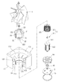
図3は本発明の第2実施形態による内ローター式放熱ファンの分解斜視図で、図4は本発明の第2実施形態による内ローター式放熱ファンの組み立てられた状態の断面図である。図3、4を参照すると、本発明の第2実施形態の内ローター式放熱ファンが掲示されており、内ローター式放熱ファンには同様にフレーム1’、シールケーシング2’、内ローター式モーター3、インペラー4および回路板5が含まれる。そして、フレーム1’、シールケーシング2’、内ローター式モーター3、インペラー4および回路板5は上述した第1実施形態に掲示されている構造と大体同じであるが、その主な差異は以下のとおりである。
FIG. 3 is an exploded perspective view of an inner rotor heat dissipation fan according to a second embodiment of the present invention, and FIG. 4 is a cross-sectional view of the assembled state of the inner rotor heat dissipation fan according to the second embodiment of the present invention. Referring to FIGS. 3 and 4, an inner rotor type heat dissipating fan according to a second embodiment of the present invention is posted. Similarly, the inner rotor type heat dissipating fan includes a
シールケーシング2’において、パンチングの方式を利用してシールケーシング2’の外周面に凹部24を形成し、またシールケーシング2’の内周面において相対するように凸部25を形成し、さらにステータ32’の外周面において位置決め溝321を形成することができる。図5は本発明の第2実施形態による内ローター式放熱ファンの図7のA−A線に沿った断面図である。図5を参照すると、射出成形の方式を利用してフレーム1’を形成することにより、固定座12が成形された後、固定座12が直接シールケーシング2’の外周面に被覆される時、上述したシールケーシング2’の構造の設計によって固定座12の内周面にはさらに係止部123が形成される。係止部123とシールケーシング2’の凹部24との間は互いに係止した結合状態が形成されることにより、シールケーシング2’が不用意に脱落したり回動したりするのを回避することができる。その他に、ステータ32’がシールケーシング2’の内部に取り付けられる時、ステータ32’の位置決め溝321を合わせてシールケーシング2’の凸部25を係止することにより、ステータ32’がシールケーシング2’の内部において不用意に回動するのを防止することができるため、よりよい組立の便利性を提供することができる。
In the
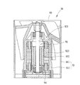
図6は本発明の第3実施形態による内ローター式放熱ファンの分解斜視図で、図7は本発明の第3実施形態による内ローター式放熱ファンの組み立てられた状態の断面図である。図6、7を参照すると、本発明の第3実施形態の内ローター式放熱ファンが掲示されており、内ローター式放熱ファンには同様にフレーム1”、シールケーシング2”、内ローター式モーター3、インペラー4および回路板5が含まれる。その中に、フレーム1”、シールケーシング2”、内ローター式モーター3、インペラー4および回路板5は上述した第1実施形態に掲示されている構造とは大体同じであり、その主な差異は下記のとおりである。
FIG. 6 is an exploded perspective view of an inner rotor heat dissipation fan according to the third embodiment of the present invention, and FIG. 7 is a cross-sectional view of the assembled state of the inner rotor heat dissipation fan according to the third embodiment of the present invention. Referring to FIGS. 6 and 7, an inner rotor type heat dissipating fan according to a third embodiment of the present invention is posted. Similarly, the inner rotor type heat dissipating fan includes a
シールケーシング2”の結合部21にはさらに拡径部211が形成され、拡径部211の底部の縁端には複数個の突出フック212が形成されることにより、シールケーシング2”の外周壁には段部213が形成される。また、フレーム1”において上述した第1実施形態に掲示されている当接部121が省かれた。射出成形の方式によってフレーム1”を形成することにより、固定座12が成形された後、固定座12がシールケーシング2’の外周面を直接被覆するように形成される時、固定座12の位置決め部122はシールケーシング2”の段部213と互いに係止した結合状態が形成されることにより、シールケーシング2”が任意に脱落したり回動したりしないのを確保することができる。その他に、回路板5、位置決め部材14とシールキャップ15がシールケーシング2”の内部に取り付けられる時、シールケーシング2”のそれぞれの突出フック212を折り曲げることにより、それぞれの突出フック212によって回路板5、位置決め部材14とシールキャップ15などの部材が脱落するのを有効に防止することができ、ひいてはよりよい結合の作用を提供することができる。或いは、シールケーシング2”は直接鋲着の方式によって回路板5、位置決め部材14とシールキャップ15などの部材を固定することができるため、組立の便利性を高めることができる。
The
本発明の内ローター式放熱ファンを実際に使用する時、内ローター式放熱ファンを各種の電子製品の予定される発熱の部位に取り付けることができ、そしてフレーム1の風出口112は上記予定される発熱の部位に向くように配置できる。さらに回路板5を利用して内ローター式モーター3のステータ32とローター31の磁性部材312が磁束鎖交の作用を生じさせるのを制御することにより、ローター31の回動軸311は回動して作動するように形成されるため、さらに回動軸311を経由してインペラー4が回動して作動するのを連動することができる。これにより、インペラー4が回転する時、気流を導引してフレーム1の風入口111を経由して気流通路113に進入し、それから再び気流通路113を経由して気流を集中して集中風出口112から導出されることにより、上記電子製品に対して放熱の作用を行うことができる。
When the inner rotor-type heat radiating fan of the present invention is actually used, the inner rotor-type heat radiating fan can be attached to a predetermined heat generating portion of various electronic products, and the
上述の如く、本発明の内ローター式放熱ファンによれば、内ローター式モーター3の特性を利用することによってローター31とインペラー4の回動の作動を有効的に安定化にし、そしてその回転速度を高めることができ、さらにフレーム1を利用してインペラー4から生じる気流を有効に導引して集中させることにより、放熱ファンの全体の放熱効果を高めることができる。さらに最も重要なのは、内ローター式モーター3はシールケーシング2、2’の内部に取り付けられているため、回路板5の制御によってステータ32、32’と磁性部材312との間に磁束鎖交の作用が生じられる過程において、シールケーシング2、2’そのものは磁気封止の作用を提供することにより、磁束漏洩の現象が生じるのを有効に避けることができるため、インペラー4の運転の功能には影響を受けることなく、さらに電磁妨害が生じるのを防止することができるため、全体の放熱の効果を高めることができる。
As described above, according to the inner rotor type heat radiating fan of the present invention, the operation of the rotation of the
本発明は、その精神とび必須の特徴事項から逸脱することなく他のやり方で実施することができる。従って、本明細書に記載した好ましい実施形態は例示的なものであり、限定的なものではない。 The present invention may be implemented in other ways without departing from the spirit and essential characteristics thereof. Accordingly, the preferred embodiments described herein are exemplary and not limiting.
1、1’、1” フレーム
11 框体
111 風入口
112 風出口
113 気流通路
12 固定座
121 当接部
122 位置決め部
123 係止部
13 連接部材
14 位置決め部材
15 シールキャップ
16 第一軸受け
2、2’、2” シールケーシング
21 結合部
211 拡径部
212 突出フック
213 段部
22 第一開口
221 収容室
222 第二軸受け
23 第二開口
24 凹部
25 凸部
3 内ローター式モーター
31 ローター
311 回動軸
312 磁性部材
32、32’ ステータ
321 位置決め溝
4 インペラー
5 回路板
70 放熱ファン
71 フレーム
711 軸管
712 軸受け
72 ステータ
73 回路板
74 ローター
741 回動軸
742 インペラー
743 永久磁石
80 放熱ファン
81 框体
811 第一框体
812 第二框体
82 ステータ構造
821 磁気導引部材
83 ローター構造
84 駆動装置
85 インペラー
90 放熱ファン
91 フレーム
911 フレーム部
912 モーターフレーム
92 内ローター式モーター
921 回動軸
922 磁性部材
923 ステータ
93 インペラー
94 回路板
DESCRIPTION OF
Claims (7)
Applications Claiming Priority (2)
| Application Number | Priority Date | Filing Date | Title |
|---|---|---|---|
| TW097136470A TWI373903B (en) | 2008-09-23 | 2008-09-23 | Inner-rotor type fan |
| TW097136470 | 2008-09-23 |
Publications (2)
| Publication Number | Publication Date |
|---|---|
| JP2010077963A JP2010077963A (en) | 2010-04-08 |
| JP5102811B2 true JP5102811B2 (en) | 2012-12-19 |
Family
ID=42037447
Family Applications (1)
| Application Number | Title | Priority Date | Filing Date |
|---|---|---|---|
| JP2009154282A Active JP5102811B2 (en) | 2008-09-23 | 2009-06-29 | Inner rotor type heat dissipation fan |
Country Status (3)
| Country | Link |
|---|---|
| US (1) | US7976292B2 (en) |
| JP (1) | JP5102811B2 (en) |
| TW (1) | TWI373903B (en) |
Families Citing this family (18)
| Publication number | Priority date | Publication date | Assignee | Title |
|---|---|---|---|---|
| TWI411200B (en) * | 2010-07-12 | 2013-10-01 | Sunonwealth Electr Mach Ind Co | Motor and heat dissipating fan with the motor |
| JP2012102686A (en) * | 2010-11-11 | 2012-05-31 | Nippon Densan Corp | Ventilation fan |
| JP5395843B2 (en) | 2011-01-10 | 2014-01-22 | 建準電機工業股▲分▼有限公司 | Heat dissipation fan |
| KR101197950B1 (en) * | 2011-04-13 | 2012-11-05 | 뉴모텍(주) | Fan Motor |
| TWI448048B (en) * | 2011-09-01 | 2014-08-01 | Sunonwealth Electr Mach Ind Co | Miniaturized fan and a cooling fan utilizing the same |
| CN102444597A (en) * | 2012-01-04 | 2012-05-09 | 大连海密梯克泵业有限公司 | Magnetic transmission fan |
| KR101930333B1 (en) * | 2012-06-15 | 2018-12-18 | 엘지이노텍 주식회사 | Motor |
| TWI525966B (en) * | 2013-11-29 | 2016-03-11 | Sunonwealth Electruc Machine Industry Co Ltd | Motor and its motor shock mechanism |
| CN105871115B (en) * | 2016-05-17 | 2018-03-16 | 西安交通大学 | A kind of mixing actuator and start method based on electromagnetic drive piezoelectricity clamper |
| US10184477B2 (en) * | 2016-12-05 | 2019-01-22 | Asia Vital Components Co., Ltd. | Series fan inclination structure |
| CN108425866B (en) * | 2017-02-14 | 2020-08-28 | 台达电子工业股份有限公司 | Thin fan |
| EP4234949A3 (en) * | 2017-03-16 | 2023-10-04 | LG Electronics Inc. | Motor fan |
| CN107803578B (en) * | 2017-11-10 | 2023-06-23 | 嘉兴职业技术学院 | Positioning device of electric welding machine |
| TWI650487B (en) * | 2018-03-08 | 2019-02-11 | 建準電機工業股份有限公司 | fan |
| TWI674736B (en) * | 2018-05-09 | 2019-10-11 | 建準電機工業股份有限公司 | Motor rotor |
| JP2020133550A (en) * | 2019-02-22 | 2020-08-31 | 日本電産株式会社 | Axial flow fan |
| US11118600B2 (en) * | 2019-11-18 | 2021-09-14 | Asia Vital Components Co., Ltd. | Anti-press fan structure |
| CN114673671B (en) * | 2020-12-25 | 2024-04-02 | 广东美的白色家电技术创新中心有限公司 | Blower and dust suction device |
Family Cites Families (22)
| Publication number | Priority date | Publication date | Assignee | Title |
|---|---|---|---|---|
| US2823849A (en) * | 1953-05-15 | 1958-02-18 | Voith Gmbh J M | Fluid drive for turbo units |
| US3303995A (en) * | 1964-09-08 | 1967-02-14 | Rotron Mfg Co | Fan motor cooling arrangement |
| JPS5541742U (en) * | 1978-09-11 | 1980-03-18 | ||
| JPS62134000U (en) * | 1986-02-17 | 1987-08-24 | ||
| JPS62156199U (en) * | 1986-03-26 | 1987-10-03 | ||
| DE4334124A1 (en) * | 1993-03-04 | 1994-09-08 | Bosch Gmbh Robert | Device for receiving an electric motor |
| JP3545846B2 (en) * | 1995-06-14 | 2004-07-21 | 株式会社ミツバ | Drain structure of fan motor |
| DE19706852A1 (en) * | 1997-02-21 | 1998-09-03 | Bosch Gmbh Robert | Holding device for an electric motor |
| US5917258A (en) * | 1997-10-08 | 1999-06-29 | Siemens Canada Limited | Bearing assembly for an ultra quiet electric motor |
| JP3318531B2 (en) * | 1998-08-04 | 2002-08-26 | ミネベア株式会社 | Rotating electric machine and its bearing structure |
| US6069423A (en) * | 1999-04-21 | 2000-05-30 | Vita-Mix Corporation | Motor cooling and sound absorbing system |
| JP2001157393A (en) * | 1999-11-19 | 2001-06-08 | Minebea Co Ltd | Rotor structure for inner rotor-type motor |
| JP3482373B2 (en) * | 2000-04-28 | 2003-12-22 | ミネベア株式会社 | Blower |
| JP2003009470A (en) * | 2001-06-21 | 2003-01-10 | Toshiba Corp | Fan motor |
| DE10131590A1 (en) * | 2001-07-03 | 2003-01-16 | Bosch Gmbh Robert | Device for fastening an electric motor |
| DE20308665U1 (en) * | 2003-06-03 | 2004-12-30 | Minebea Co., Ltd. | Internal rotor electric motor |
| JP2005256676A (en) * | 2004-03-10 | 2005-09-22 | Koyo Seiko Co Ltd | Electric pump unit |
| JP4823694B2 (en) * | 2006-01-13 | 2011-11-24 | 日本電産コパル株式会社 | Small fan motor |
| TW200744290A (en) | 2006-05-26 | 2007-12-01 | Delta Electronics Inc | Fan and motor with inner rotor thereof |
| TWI322551B (en) * | 2006-07-28 | 2010-03-21 | Delta Electronics Inc | Fan for vehicle and its used motor |
| US20080197731A1 (en) * | 2007-02-15 | 2008-08-21 | Nidec Corporation | Brushless motor and pump mounted with brushless motor |
| JP5039439B2 (en) * | 2007-06-12 | 2012-10-03 | アイシン精機株式会社 | Electric pump rotor |
-
2008
- 2008-09-23 TW TW097136470A patent/TWI373903B/en active
- 2008-10-15 US US12/251,512 patent/US7976292B2/en active Active
-
2009
- 2009-06-29 JP JP2009154282A patent/JP5102811B2/en active Active
Also Published As
| Publication number | Publication date |
|---|---|
| US7976292B2 (en) | 2011-07-12 |
| US20100073873A1 (en) | 2010-03-25 |
| TW201014124A (en) | 2010-04-01 |
| TWI373903B (en) | 2012-10-01 |
| JP2010077963A (en) | 2010-04-08 |
Similar Documents
| Publication | Publication Date | Title |
|---|---|---|
| JP5102811B2 (en) | Inner rotor type heat dissipation fan | |
| US7800263B2 (en) | Heat dissipating fan | |
| JP4881354B2 (en) | Miniature fan | |
| JP6104566B2 (en) | Electric water pump | |
| TW200845878A (en) | Fan and fan assembly | |
| US20130171014A1 (en) | Advection Fans | |
| JP2012222338A (en) | Heat dissipation system including horizontal convection fan | |
| EP1653591A1 (en) | Self-cooling electric machine | |
| CN201284749Y (en) | Inner rotor type cooling fan | |
| US20100316514A1 (en) | Heat-Dissipating Fan | |
| JP2019082115A (en) | Centrifugal fan | |
| CN107204675A (en) | Electric power unit | |
| CN218733539U (en) | Protective cover for permanent magnet synchronous motor | |
| JP2012180810A (en) | Air blowing device | |
| JP6450928B2 (en) | Electric blower and electric vacuum cleaner using the same | |
| JP6950422B2 (en) | Centrifugal fan | |
| US8820692B2 (en) | Motor casing and a motor utilizing the same | |
| JP2011153549A (en) | Pump device | |
| CN101713413B (en) | Inner rotor type radiator fan | |
| US20080100172A1 (en) | Electric fan | |
| JP4809911B2 (en) | fan | |
| TWI413346B (en) | Fan case | |
| KR101918068B1 (en) | Motor combined with fan | |
| JP2005273592A (en) | Centrifugal fan | |
| JP2006066866A (en) | Fan frame |
Legal Events
| Date | Code | Title | Description |
|---|---|---|---|
| A977 | Report on retrieval |
Free format text: JAPANESE INTERMEDIATE CODE: A971007 Effective date: 20111130 |
|
| A131 | Notification of reasons for refusal |
Free format text: JAPANESE INTERMEDIATE CODE: A131 Effective date: 20111206 |
|
| A521 | Request for written amendment filed |
Free format text: JAPANESE INTERMEDIATE CODE: A523 Effective date: 20120210 |
|
| TRDD | Decision of grant or rejection written | ||
| A01 | Written decision to grant a patent or to grant a registration (utility model) |
Free format text: JAPANESE INTERMEDIATE CODE: A01 Effective date: 20120904 |
|
| A01 | Written decision to grant a patent or to grant a registration (utility model) |
Free format text: JAPANESE INTERMEDIATE CODE: A01 |
|
| A61 | First payment of annual fees (during grant procedure) |
Free format text: JAPANESE INTERMEDIATE CODE: A61 Effective date: 20120928 |
|
| FPAY | Renewal fee payment (event date is renewal date of database) |
Free format text: PAYMENT UNTIL: 20151005 Year of fee payment: 3 |
|
| R150 | Certificate of patent or registration of utility model |
Free format text: JAPANESE INTERMEDIATE CODE: R150 Ref document number: 5102811 Country of ref document: JP Free format text: JAPANESE INTERMEDIATE CODE: R150 |
|
| R250 | Receipt of annual fees |
Free format text: JAPANESE INTERMEDIATE CODE: R250 |
|
| R250 | Receipt of annual fees |
Free format text: JAPANESE INTERMEDIATE CODE: R250 |
|
| R250 | Receipt of annual fees |
Free format text: JAPANESE INTERMEDIATE CODE: R250 |
|
| S531 | Written request for registration of change of domicile |
Free format text: JAPANESE INTERMEDIATE CODE: R313531 |
|
| R350 | Written notification of registration of transfer |
Free format text: JAPANESE INTERMEDIATE CODE: R350 |
|
| R250 | Receipt of annual fees |
Free format text: JAPANESE INTERMEDIATE CODE: R250 |
|
| R250 | Receipt of annual fees |
Free format text: JAPANESE INTERMEDIATE CODE: R250 |
|
| R250 | Receipt of annual fees |
Free format text: JAPANESE INTERMEDIATE CODE: R250 |
|
| R250 | Receipt of annual fees |
Free format text: JAPANESE INTERMEDIATE CODE: R250 |
|
| R250 | Receipt of annual fees |
Free format text: JAPANESE INTERMEDIATE CODE: R250 |
|
| R250 | Receipt of annual fees |
Free format text: JAPANESE INTERMEDIATE CODE: R250 |