JP5101700B2 - High pressure discharge lamp with partial coating and vehicle headlight with the high pressure discharge lamp - Google Patents
High pressure discharge lamp with partial coating and vehicle headlight with the high pressure discharge lamp Download PDFInfo
- Publication number
- JP5101700B2 JP5101700B2 JP2010526247A JP2010526247A JP5101700B2 JP 5101700 B2 JP5101700 B2 JP 5101700B2 JP 2010526247 A JP2010526247 A JP 2010526247A JP 2010526247 A JP2010526247 A JP 2010526247A JP 5101700 B2 JP5101700 B2 JP 5101700B2
- Authority
- JP
- Japan
- Prior art keywords
- discharge lamp
- pressure discharge
- coating
- discharge
- lamp according
- Prior art date
- Legal status (The legal status is an assumption and is not a legal conclusion. Google has not performed a legal analysis and makes no representation as to the accuracy of the status listed.)
- Expired - Fee Related
Links
Images

Classifications
-
- H—ELECTRICITY
- H01—ELECTRIC ELEMENTS
- H01J—ELECTRIC DISCHARGE TUBES OR DISCHARGE LAMPS
- H01J61/00—Gas-discharge or vapour-discharge lamps
- H01J61/02—Details
- H01J61/30—Vessels; Containers
- H01J61/35—Vessels; Containers provided with coatings on the walls thereof; Selection of materials for the coatings
Abstract
Description
本発明は、少なくとも1つの放電容器と、この放電容器の放電空間内に延在する2つの電極とを有し、これら2つの電極間には高圧放電ランプの駆動時に光を発するアークが生じる、殊に車両ヘッドライト用の高圧放電ランプに関する。さらに本発明は、少なくとも1つのこの種の高圧放電ランプが設けられている車両ヘッドライトにも関する。 The present invention has at least one discharge vessel and two electrodes extending into the discharge space of the discharge vessel, and an arc that emits light is generated between the two electrodes when the high-pressure discharge lamp is driven. More particularly, the present invention relates to a high pressure discharge lamp for a vehicle headlight. The invention further relates to a vehicle headlight provided with at least one such high-pressure discharge lamp.
この種の高圧放電ランプは例えばインターネットドメインwww.osram.deにおいて製品名「XENARC(R)」に示されている。これらの従来の放電ランプは、イオン化可能な充填物で充填されており、また2つの電極が延在している放電空間を境界付ける放電容器を有する。2つの電極はエネルギ供給のために放電容器から突出した給電部と接続されており、またランプの駆動時に光を発する放電アークを生じさせるガス放電を形成する。 Shown in the product name "Xenarc (R)" in this type of high pressure discharge lamp, for example Internet domain Www.Osram.De. These conventional discharge lamps are filled with an ionizable filling and have a discharge vessel that bounds the discharge space in which the two electrodes extend. The two electrodes are connected to a power feeding portion protruding from the discharge vessel for supplying energy, and form a gas discharge that generates a discharge arc that emits light when the lamp is driven.
点火特性を改善するために、例えばDE 10 2004 043 636 A1からは、導電性で光透過性の層が少なくとも部分的なコーティング部として放電容器の表面に被着されている高圧放電ランプが公知である。このコーティング部は電極と共に、また場合によっては給電部と共にコンデンサを形成し、その間に位置する放電容器のガラスおよび放電容器内の充填ガスがこのコンデンサの誘電体を形成する。これによって、殊に点火パルスの高周波成分を用いて、放電容器内では電極とコーティング部との間の誘電的に妨害された放電が生じる。この誘電的に妨害された放電は、放電空間内に多数の自由キャリアを生成し、高圧放電ランプの2つの電極間の電気的な降伏を実現する、もしくはそのために必要な点火電圧を著しく低減する。
In order to improve the ignition characteristics, for example,
この種の高圧放電ランプにおける欠点は、放電アークの色温度および輝度が放電アークの長さにわたり不均一に生じていることにより、殊にこの種の高圧放電ランプが自動車ヘッドライトにおいて使用される場合にはランプから発せられる光が他の道路使用者を幻惑させる虞があることである。殊に、過度に高い色温度を有する、この種のランプの放電空間内のいわゆるホットスポットが対向車両の幻惑を生じさせる可能性がある。 The disadvantage of this type of high-pressure discharge lamp is that the color temperature and brightness of the discharge arc are not uniform over the length of the discharge arc, especially when this type of high-pressure discharge lamp is used in automotive headlights. There is a possibility that the light emitted from the lamp may dazzle other road users. In particular, so-called hot spots in the discharge space of this type of lamp, which have an excessively high color temperature, can cause the oncoming vehicle to become dazzled.
発明の開示
本発明が基礎となる課題は、従来の解決手段に比べて改善された輝度効果が実現されている、少なくとも1つのこの種の高圧放電ランプを備えた高圧放電ランプおよび車両ヘッドライトを提供することである。
DISCLOSURE OF THE INVENTION The problem underlying the present invention is to provide a high-pressure discharge lamp and a vehicle headlight comprising at least one high-pressure discharge lamp of this kind, which realizes an improved luminance effect compared to the conventional solutions. Is to provide.
この課題は、少なくとも1つの放電容器と、放電容器の放電空間内に延在する2つの電極とを有し、2つの電極間には高圧放電ランプの駆動時に光を発する放電アークが生じ、ランプの周囲面上に電極の少なくとも一方の放電空間側の端部セクションの領域において、発せられる光の輝度および色温度を変化させる部分的なコーティング部が被着されている、高圧放電ランプによって解決される。さらにこの課題は、少なくとも1つのこの種の高圧放電ランプを備えた車両ヘッドライトによって解決される。本発明の殊に有利な実施形態は従属請求項に記載されている。 This problem includes at least one discharge vessel and two electrodes extending into the discharge space of the discharge vessel, and a discharge arc is generated between the two electrodes that emits light when the high-pressure discharge lamp is driven. This is solved by a high-pressure discharge lamp in which a partial coating is applied on the peripheral surface of the electrode in the region of the end section on the discharge space side of at least one of the electrodes to change the brightness and color temperature of the emitted light. The Furthermore, this problem is solved by a vehicle headlight comprising at least one such high-pressure discharge lamp. Particularly advantageous embodiments of the invention are described in the dependent claims.
少なくとも1つの電極の放電空間側の端部セクションの領域における高圧放電ランプの本発明によるコーティング部に基づき、ランプの色および輝度がより均一になり、他の道路使用者、例えば対向車両のドライバがもはや眩惑されない、または少なくとも余り眩惑されないことが達成される。何故ならば、輝度ならびに色温度がこの種の部分コーティング部によって変更されるからである。さらに、この種の部分コーティング部によって実際の発光体の幾何学を非常に正確に調整することができる。これによって、例えばヘッドライトのリフレクタ幾何学をさらに良好に高圧放電ランプに適合させることができるので、改善された輝度効果が達成される。本発明の殊に有利な実施例によれば、部分的なコーティング部が発せられる光の輝度および色温度を低減させるコーティングとして構成されている。 Based on the coating part according to the invention of the high-pressure discharge lamp in the region of the end section on the discharge space side of the at least one electrode, the color and brightness of the lamp become more uniform and other road users, for example drivers of oncoming vehicles, It is achieved that it is no longer dazzled or at least not too dazzled. This is because the brightness and color temperature are changed by this type of partial coating. Furthermore, the geometry of the actual illuminant can be adjusted very accurately by this type of partial coating. This achieves an improved brightness effect, for example because the reflector geometry of the headlight can be better adapted to the high-pressure discharge lamp. According to a particularly advantageous embodiment of the invention, the partial coating is designed as a coating that reduces the brightness and color temperature of the emitted light.
本発明の有利な実施形態において、ランプの放電容器は安全性の理由から、少なくとも部分的に外管によって包囲されている。コーティング部を外管の外周面および/または放電容器の外周面上に被着させることができる。外管の外周面上に被着されているコーティング部は、放電容器上に被着されているコーティング部に比べて熱的な負荷が低減されている。放電容器の外周面上にコーティング部を被着することは、このコーティング部が機械的な損傷から保護されており、また外管と放電容器との間の空間に存在するガス充填物、殊に不活性ガスによるコーティング部の不所望な反応を回避できるという利点を有する。しかしながら本発明は、外管を備えたタイプのランプに限定されるものではなく、むしろ外管を備えておらず、放電容器上に被着されているコーティング部を備えた高圧放電ランプを構成することもできる。 In an advantageous embodiment of the invention, the discharge vessel of the lamp is at least partly surrounded by an outer tube for safety reasons. The coating portion can be deposited on the outer peripheral surface of the outer tube and / or the outer peripheral surface of the discharge vessel. The coating portion deposited on the outer peripheral surface of the outer tube has a reduced thermal load compared to the coating portion deposited on the discharge vessel. The deposition of the coating on the outer peripheral surface of the discharge vessel means that the coating is protected from mechanical damage and that the gas filling present in the space between the outer tube and the discharge vessel, in particular There is an advantage that an undesirable reaction of the coating portion by the inert gas can be avoided. However, the present invention is not limited to the type of lamp provided with an outer tube, but rather comprises a high-pressure discharge lamp that does not include an outer tube but includes a coating portion deposited on the discharge vessel. You can also.
有利には、2つの電極の放電空間側の端部セクションの領域内において、外管および/または放電容器の周囲面上にはそれぞれ1つのコーティング部が被着されている。高圧放電ランプの本発明による実施形態においては、コーティング部が少なくとも、外管および/または放電容器の外周セクションに被着されている。 Advantageously, in the region of the end section on the discharge space side of the two electrodes, one coating is deposited on the outer surface of the outer tube and / or the discharge vessel, respectively. In an embodiment according to the invention of a high-pressure discharge lamp, the coating is applied at least to the outer tube and / or the outer peripheral section of the discharge vessel.
コーティング部がリング状に外管および/または放電容器の周囲に延在する場合には殊に有利であることが分かった。コーティング部は、非常に明るく高い色温度を有する白色のホットスポットのリング状の遮蔽部を形成するので、ランプの色温度および輝度はより均一になる。 It has been found to be particularly advantageous if the coating extends in the form of a ring around the outer tube and / or the discharge vessel. The coating portion forms a white hot spot ring-shaped shield having a very bright and high color temperature, so that the color temperature and brightness of the lamp are more uniform.
本発明による高圧放電ランプの実施形態においては、コーティング部が間隔を置いて電極の端部セクションを包囲するように、コーティング部が外管または放電容器上に被着されている。コーティング部がそれぞれ電極の放電空間側の端部セクションの手前において約0.2mm〜1.2mm、有利には0.5mmの間隔を置いた位置から出発して被着されており、放電容器の端部セクションの方向に向かって延在している。有利には、各コーティング部は少なくとも放電空間から高圧放電ランプの放電容器内の電極のヒューズシールにまで延在している。 In an embodiment of the high-pressure discharge lamp according to the invention, the coating part is deposited on the outer tube or the discharge vessel so that the coating part is spaced and surrounds the end section of the electrode. Each of the coatings is deposited starting from a position spaced about 0.2 mm to 1.2 mm, preferably 0.5 mm, in front of the end section on the discharge space side of the electrode. It extends in the direction of the end section. Advantageously, each coating extends from at least the discharge space to the electrode fuse seal in the discharge vessel of the high-pressure discharge lamp.
本発明の択一的な実施例においては、コーティング部が電極の一方の端部から出発して外管または放電容器上にそれぞれ被着されており、また放電容器の端部セクションの方向に延在している。このヴァリエーションにおいては、電極の端部の領域において放射されるビームの少なくとも一部がコーティング部によって捕捉されないので、非常に高い輝度が達成される。 In an alternative embodiment of the invention, the coating is deposited on the outer tube or discharge vessel starting from one end of the electrode and extending in the direction of the end section of the discharge vessel. Exist. In this variation, very high brightness is achieved because at least part of the beam emitted in the region of the end of the electrode is not captured by the coating.
コーティング部の位置および幾何学を制御するために、コーティング部は例えばマスク技術またはスクリーン技術により被着される。 In order to control the position and geometry of the coating part, the coating part is applied, for example, by mask technology or screen technology.
本発明によるコーティング部は有利には少なくとも1つの吸収フィルタ、干渉フィルタおよび/またはこの種のフィルタの組合せを有する。コーティング部の構成に応じて、放電アークから発せられる光の吸収または部分的な吸収が達成される。干渉フィルタ装置によって、眩惑を惹起する不所望な波長領域の光を放電ランプの放射スペクトルからフィルタリングすることができる。 The coating according to the invention preferably has at least one absorption filter, interference filter and / or a combination of such filters. Depending on the configuration of the coating part, absorption or partial absorption of light emitted from the discharge arc is achieved. The interference filter device can filter out light in an undesired wavelength region that causes dazzling from the radiation spectrum of the discharge lamp.
本発明による実施形態においては、コーティング部が真空コーティング法によって外管および/または放電容器上に被着されている。真空コーティング法においては、規定の層厚および高い付着性を有するコーティング部が達成される。ここで有利には、真空コーティングプロセスは連続的に実施され、すなわち真空チャンバの中間換気を行うことなく実施され、これによってコーティング部の汚染は生じないので、高圧放電ランプのコーティング部の品質はさらに改善されている。輝度効果の所望の改善を達成するために、コーティング部の光学的な特性を使用される材料、層幾何学および層厚によって簡単に調整することができる。コーティング部を1つまたは複数の材料から構成することができる。 In an embodiment according to the present invention, the coating part is deposited on the outer tube and / or the discharge vessel by a vacuum coating method. In the vacuum coating method, a coating portion having a specified layer thickness and high adhesion is achieved. Advantageously, the quality of the coating part of the high-pressure discharge lamp is further improved since the vacuum coating process is carried out continuously, i.e. without any intermediate ventilation of the vacuum chamber, thereby causing no contamination of the coating part. It has been improved. In order to achieve the desired improvement in the brightness effect, the optical properties of the coating can be easily adjusted by the materials used, the layer geometry and the layer thickness. The coating portion can be composed of one or more materials.
本発明の殊に有利な実施例においては、コーティング部がPVDスパッタリング技術またはCVD技術により被着されている。例えば反応性PVDスパッタリングプロセスが使用される。 In a particularly advantageous embodiment of the invention, the coating is applied by PVD sputtering or CVD techniques. For example, a reactive PVD sputtering process is used.
殊に、車両ヘッドライトに使用される高圧放電ランプにおいては、外管ないし放電容器の外周面のコーティングされていないセクションが有利には、ECE規格に従い必要とされる照明強度を達成するためには十分に高い輝度を有する。 In particular, in high-pressure discharge lamps used for vehicle headlights, an uncoated section of the outer surface of the outer tube or discharge vessel is preferably used to achieve the required illumination intensity according to the ECE standard. It has a sufficiently high brightness.
以下では、本発明を有利な実施例に基づいて詳細に説明する。 In the following, the invention will be described in detail on the basis of advantageous embodiments.
本発明を以下では、例えば車両ヘッドライトにおいて使用されるような高圧放電ランプに基づいて説明する。しかしながら本発明による高圧放電ランプは、この形式のランプに限定されるものではない。 The invention will be described below on the basis of a high-pressure discharge lamp as used, for example, in vehicle headlights. However, the high-pressure discharge lamp according to the invention is not limited to this type of lamp.
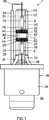
図1は、石英ガラスから成る放電容器2(バーナ)を備えた高圧放電ランプ1の概略図を示す。放電容器2は放電空間4の境界をなし、また直径上に配置されシールされている端部セクション6,8を有し、これらの端部セクション6,8内には気密に電流を流すためのモリブデンフィルム10がそれぞれ1つずつ埋め込まれている。モリブデンフィルム10は第1の狭隘側12においてドープされたモリブデンから成る外部給電部14,16と接続されている。放電容器2の放電空間4内には直径上に配置されている2つの電極18,20が突出しており、これら2つの電極18,20はドープされたタングステンから成り、またモリブデンフィルム10の第2の狭隘側22とそれぞれ接続されている。これら2つの電極間にはランプの駆動中に光を発するガス放電が生じる。放電容器2の放電空間4内にはイオン化可能な充填物が封入されており、この充填物は高純度のキセノンガスおよび複数の金属ハロゲン化物から成る。放電容器2は外管24によって包囲されており、この外管24は紫外線放射を吸収するドーパントを有する石英ガラスから成る。さらに高圧放電ランプ1は、放電容器2および外管24を支持するランプソケット26を有する。ランプソケット26は、図示されていないランプホルダ内に収容するための絶縁性プラスチックから成る部分的に円筒状のソケットケーシング28を有する。このソケットケーシング28はランプ側において、このソケットケーシング28に外管24を固定するための固定リング32を備えた固定セクション30を有する。放電容器2においてソケット側とは反対側に位置する外部給電部14は、絶縁スリーブ34によって包囲されている電流帰還部36を介して、ランプソケット26の電気的な接続リング38と接続されており、他方ではソケット側の外部給電部16は高圧放電ランプ1の図示されていない内部接触ピンと接続されている。
FIG. 1 shows a schematic view of a high-
外管24の外周面40には、各電極18,20の放電空間側の端部セクション42の領域において、発せられる光の輝度および色温度を変化させる、殊に低下させる部分的なコーティング部44が被着されている。コーティング部44はそれぞれ、これらのコーティング部44が間隔を置いて電極18,20の端部セクション42を包囲し、且つ放電容器2内の電極6,8のヒューズシール48にまで延びるように、ほぼリング状に外管24上に被着されている。高圧放電ランプ1の本発明によるコーティング部44に基づき、ランプの色および輝度をより均一にすることができ、また他の道路使用者、例えば対向車両のドライバがもはや眩惑されない、または少なくとも余り眩惑されないことが達成される。何故ならば、輝度ならびに色温度がこの種の部分コーティング部44によって低減されるからである。さらに、この種の部分コーティング部44によって実際の発光体の幾何学を非常に正確に調整することができる。これによって、例えばヘッドライトのリフレクタ幾何学をさらに良好に高圧放電ランプ1に適合させることができるので、改善された輝度効果が達成される。外管24の外周面40上にコーティング部44が被着されることにより、放電容器2上にコーティング部が被着される場合に比べて熱的な負荷は低減される。外管24の外周面40のコーティングされていないセクション46は、ECEによって道路照明のために要求される照明強度を達成するためには十分に高い輝度を有する。
On the outer
本発明の図示されていない実施例においては、コーティング部44が放電容器2上に被着されている。放電容器2の外周面上にコーティング部44を被着することは、このコーティング部44が機械的な損傷から保護されており、また外管と放電容器との間の空間に存在するガス充填物、殊に不活性ガスによるコーティング部の不所望な反応を回避できるという利点を有する。さらにはコーティング部44を電極18,20の一方の端部から出発して外管24または放電容器2上にそれぞれ被着させ、放電容器2の端部セクション6,8の方向に延在させることができる。
In a non-illustrated embodiment of the invention, a
コーティング部44は少なくとも1つの吸収フィルタ、干渉フィルタおよび/またはこの種のフィルタの組み合わせを有し、図示されている実施例においては真空コーティング法によって外管24上に被着されている。コーティング部44の位置および幾何学を制御するために、コーティング部44は例えばマスク技術またはスクリーン技術により被着される。真空コーティング法においては、規定の層厚および高い付着性を有するコーティング部が達成される。ここで有利には、真空コーティングプロセスは連続的に実施され、すなわち真空チャンバの中間換気を行うことなく実施され、これによってコーティング部の汚染は生じないので、高圧放電ランプ1のコーティング部の品質はさらに改善されている。輝度効果の所望の改善を達成するために、コーティング部44の光学的な特性を使用される材料、層幾何学および層厚によって簡単に調整することができる。コーティング部を種々の材料から構成することができる。例えば、コーティング部をPVDスパッタリング技術またはCVD技術により被着させることができる。
The
概略的に示されている放電アーク50を有する放電空間4の領域における図1の高圧放電ランプ1の拡大図を示す図2によれば、この図示されている実施例におけるコーティング部44はそれぞれ、電極18,20の放電空間側の端部セクション42の手前において約0.2〜1.2mm、有利には0.5mmの間隔Xを置いた位置から出発して、放電容器2の端部セクション6,8の方向に向かって延在している(図1を参照されたい)。コーティング部44は電極18,20の縁部領域において生じる、非常に明るく高い色温度を有する白色のホットスポット52のリング状の遮蔽部を形成するので、ランプの色温度および輝度はより均一になる。図示されている本発明の実施例において光アーク長Lは約5mmである。幅Tを有する放電アーク50の中心領域54は最大輝度の少なくとも約50%の輝度を有する。幅Tを有する放電アーク50のセクション56は最大輝度の少なくとも約20%の輝度を示し、輝度の中心58は基準軸60から間隔Rを置いている。
According to FIG. 2 which shows an enlarged view of the high-
本発明による高圧放電ランプ1は外管24を備えたランプに限定されるものではなく、むしろ外管24を備えておらず、放電容器2上に被着されているコーティング部44を備えた高圧放電ランプを実施することもできる。さらに、コーティング部44の幾何学も前述の実施例に限定されるものではない。殊に、コーティング部44を外管24または放電容器2の1つまたは複数の周囲セクションにのみ被着させることができる。
The high-
少なくとも1つの放電容器2と、放電容器2の放電空間4内に延在する2つの電極18,20とを有し、これら2つの電極18,20間には高圧放電ランプ1の駆動時に光を発する放電アーク50が生じる、殊に車両ヘッドライト用の高圧放電ランプ1が開示されており、この高圧放電ランプ1では、ランプの周囲面40上に電極18,20の少なくとも一方の放電空間側の端部セクション42の領域において、発せられる光の輝度および色温度を変化させる部分的なコーティング部44が被着されている。さらに、少なくとも1つのこの種の高圧放電ランプを備えた車両ヘッドライトが開示されている。
At least one
1 高圧放電ランプ、 2 放電容器、 4 放電空間、 6,8,42 端部セクション、 10 モリブデンフィルム、 12,22 狭隘側、 14,16 給電部、 18,20 電極、 24 外管、 26 ランプソケット、 28 ソケットケーシング、 30 固定セクション、 32 固定リング、 34 絶縁スリーブ、 36 電流帰還部、 38 接続リング、 40 外周面、 44 コーティング部、 46,56 セクション、 50 放電アーク、 52 ホットスポット、 54 領域、 58 中心、 60 基準軸
DESCRIPTION OF
Claims (12)
前記放電容器(2)は少なくとも部分的に外管(24)によって包囲されており、
前記2つの電極(18,20)の放電空間側の端部セクション(42)の領域において、発せられる前記光の輝度および色温度を低減させる部分的なコーティング部(44)が前記外管(24)の外周面上にそれぞれ1つずつ被着されていることを特徴とする、高圧放電ランプ。At least one discharge vessel (2) and two electrodes (18, 20) extending into the discharge space (4) of the discharge vessel (2), between the two electrodes (18, 20) In the high-pressure discharge lamp (1) for vehicle headlights, a discharge arc (50) that emits light is generated when the high-pressure discharge lamp (1) is driven.
The discharge vessel (2) is at least partially surrounded by an outer tube (24);
Wherein in the region of the end section of the discharge electric space side of the two electrodes (18, 20) (42), partial coating unit for reducing the luminance and the color temperature of the emitted light (44) is the outer pipe ( characterized in that it is deposited one each on the outer peripheral surface 24), the high-pressure discharge lamp.
Applications Claiming Priority (3)
| Application Number | Priority Date | Filing Date | Title |
|---|---|---|---|
| DE102007046559A DE102007046559A1 (en) | 2007-09-28 | 2007-09-28 | High-pressure discharge lamp with partial coating and vehicle headlights with such a lamp |
| DE102007046559.0 | 2007-09-28 | ||
| PCT/EP2008/062406 WO2009043726A1 (en) | 2007-09-28 | 2008-09-18 | High-pressure discharge lamp with partial coating and vehicle headlight comprising said lamp |
Publications (2)
| Publication Number | Publication Date |
|---|---|
| JP2010541142A JP2010541142A (en) | 2010-12-24 |
| JP5101700B2 true JP5101700B2 (en) | 2012-12-19 |
Family
ID=40276017
Family Applications (1)
| Application Number | Title | Priority Date | Filing Date |
|---|---|---|---|
| JP2010526247A Expired - Fee Related JP5101700B2 (en) | 2007-09-28 | 2008-09-18 | High pressure discharge lamp with partial coating and vehicle headlight with the high pressure discharge lamp |
Country Status (7)
| Country | Link |
|---|---|
| US (1) | US20100194264A1 (en) |
| EP (1) | EP2191494B1 (en) |
| JP (1) | JP5101700B2 (en) |
| CN (1) | CN101809707A (en) |
| AT (1) | ATE520146T1 (en) |
| DE (1) | DE102007046559A1 (en) |
| WO (1) | WO2009043726A1 (en) |
Families Citing this family (3)
| Publication number | Priority date | Publication date | Assignee | Title |
|---|---|---|---|---|
| JP5343768B2 (en) * | 2009-09-01 | 2013-11-13 | ウシオ電機株式会社 | High pressure discharge lamp |
| DE102011076212A1 (en) * | 2011-05-20 | 2012-11-22 | Osram Ag | DISCHARGE LAMP |
| US9607821B2 (en) * | 2011-09-13 | 2017-03-28 | Osram Sylvania Inc. | Modified spectrum incandescent lamp |
Family Cites Families (14)
| Publication number | Priority date | Publication date | Assignee | Title |
|---|---|---|---|---|
| JPS6087156U (en) * | 1983-11-16 | 1985-06-15 | 東芝ライテック株式会社 | small metal halide lamp |
| JP2974193B2 (en) * | 1992-05-15 | 1999-11-08 | 松下電子工業株式会社 | Metal halide lamps for automotive headlights |
| US5708328A (en) * | 1992-06-03 | 1998-01-13 | General Electric Company | Universal burn metal halide lamp |
| DE69514710T2 (en) | 1994-05-12 | 2000-09-28 | Iwasaki Electric Co Ltd | Metal halide lamp |
| JPH1196974A (en) * | 1997-09-18 | 1999-04-09 | Iwasaki Electric Co Ltd | Metal halide lamp with transparent heat insulating film |
| JP3603723B2 (en) * | 1999-03-26 | 2004-12-22 | 松下電工株式会社 | Metal halide lamp and discharge lamp lighting device |
| EP1168417A1 (en) * | 2000-06-26 | 2002-01-02 | General Electric Company | Incandescent lamp with an IR reflective coating and a fully reflective end coating |
| DE10204691C1 (en) * | 2002-02-06 | 2003-04-24 | Philips Corp Intellectual Pty | Mercury-free, high-intensity, high pressure gas discharge lamp for vehicle headlights, has infra-red reflecting coating on lower wall to promote vaporization |
| DE10222954A1 (en) * | 2002-05-24 | 2003-12-04 | Philips Intellectual Property | High-pressure gas discharge lamp |
| DE10247983A1 (en) | 2002-07-23 | 2004-02-05 | Philips Intellectual Property & Standards Gmbh | lamp |
| JP2004220867A (en) | 2003-01-10 | 2004-08-05 | Koito Mfg Co Ltd | Discharging bulb |
| DE102004043636A1 (en) | 2004-09-07 | 2006-03-09 | Patent-Treuhand-Gesellschaft für elektrische Glühlampen mbH | Mercury-free halogen metal-vapor high-pressure discharge lamp for vehicle headlight, has discharge vessel provided partially with coating, so that capacitive coupling is produced between coating and electrode and/or power supply lines |
| JP2006134656A (en) * | 2004-11-04 | 2006-05-25 | Harison Toshiba Lighting Corp | Metal halide lamp |
| JP2007026921A (en) * | 2005-07-19 | 2007-02-01 | Koito Mfg Co Ltd | Discharge bulb for automobile |
-
2007
- 2007-09-28 DE DE102007046559A patent/DE102007046559A1/en not_active Withdrawn
-
2008
- 2008-09-18 WO PCT/EP2008/062406 patent/WO2009043726A1/en active Application Filing
- 2008-09-18 JP JP2010526247A patent/JP5101700B2/en not_active Expired - Fee Related
- 2008-09-18 CN CN200880108660A patent/CN101809707A/en active Pending
- 2008-09-18 AT AT08804350T patent/ATE520146T1/en active
- 2008-09-18 EP EP08804350A patent/EP2191494B1/en not_active Not-in-force
- 2008-09-18 US US12/679,683 patent/US20100194264A1/en not_active Abandoned
Also Published As
| Publication number | Publication date |
|---|---|
| DE102007046559A1 (en) | 2009-04-02 |
| WO2009043726A1 (en) | 2009-04-09 |
| ATE520146T1 (en) | 2011-08-15 |
| JP2010541142A (en) | 2010-12-24 |
| EP2191494A1 (en) | 2010-06-02 |
| CN101809707A (en) | 2010-08-18 |
| EP2191494B1 (en) | 2011-08-10 |
| US20100194264A1 (en) | 2010-08-05 |
Similar Documents
| Publication | Publication Date | Title |
|---|---|---|
| US5646471A (en) | Capped high-pressure discharge lamp | |
| JP2006173108A (en) | Arc discharge light source | |
| JP5101700B2 (en) | High pressure discharge lamp with partial coating and vehicle headlight with the high pressure discharge lamp | |
| US7327086B2 (en) | Gas-discharge lamp with a colour-compensating filter | |
| KR20000034948A (en) | Discharge lamp and lighting system having a discharge lamp | |
| KR20060053115A (en) | Electric incandescent lamp for vehicle headlights | |
| JP5032734B2 (en) | Mercury-free high-pressure gas discharge lamp | |
| KR101445789B1 (en) | High-pressure discharge lamp and vehicle headlight with high-pressure discharge lamp | |
| CN1647242A (en) | High-pressure discharge lamp | |
| US20090289550A1 (en) | High-pressure mercury discharge lamp | |
| WO2011148295A2 (en) | Gas-discharge lamp | |
| CN1577715A (en) | Ignitor for short arc discharge lamp | |
| JP2010049983A (en) | Metal halide lamp and headlight for automobile | |
| JPH029442Y2 (en) | ||
| EP2313911B1 (en) | Motor vehicle lamp | |
| US20060262535A1 (en) | Vehicle headlamp | |
| TWI679677B (en) | Electric discharge lamp | |
| JP6202462B2 (en) | Discharge lamp and vehicle lamp | |
| CN104733281A (en) | Discharge lamp and vehicle lamp | |
| JP2010244831A (en) | Discharge lamp for vehicle | |
| WO2008142630A1 (en) | Discharge lamp and headlights for a motor vehicle | |
| JPH029443Y2 (en) | ||
| JP2010257848A (en) | Vehicular headlight | |
| WO2011045696A2 (en) | Discharge lamp with distortion reduced discharge vessel | |
| JP2012119227A (en) | Vehicular headlamp |
Legal Events
| Date | Code | Title | Description |
|---|---|---|---|
| RD04 | Notification of resignation of power of attorney |
Free format text: JAPANESE INTERMEDIATE CODE: A7424 Effective date: 20101228 |
|
| A977 | Report on retrieval |
Free format text: JAPANESE INTERMEDIATE CODE: A971007 Effective date: 20111216 |
|
| A131 | Notification of reasons for refusal |
Free format text: JAPANESE INTERMEDIATE CODE: A131 Effective date: 20111222 |
|
| A601 | Written request for extension of time |
Free format text: JAPANESE INTERMEDIATE CODE: A601 Effective date: 20120321 |
|
| A602 | Written permission of extension of time |
Free format text: JAPANESE INTERMEDIATE CODE: A602 Effective date: 20120328 |
|
| A521 | Request for written amendment filed |
Free format text: JAPANESE INTERMEDIATE CODE: A523 Effective date: 20120419 |
|
| A131 | Notification of reasons for refusal |
Free format text: JAPANESE INTERMEDIATE CODE: A131 Effective date: 20120516 |
|
| A521 | Request for written amendment filed |
Free format text: JAPANESE INTERMEDIATE CODE: A523 Effective date: 20120815 |
|
| TRDD | Decision of grant or rejection written | ||
| A01 | Written decision to grant a patent or to grant a registration (utility model) |
Free format text: JAPANESE INTERMEDIATE CODE: A01 Effective date: 20120829 |
|
| A01 | Written decision to grant a patent or to grant a registration (utility model) |
Free format text: JAPANESE INTERMEDIATE CODE: A01 |
|
| A61 | First payment of annual fees (during grant procedure) |
Free format text: JAPANESE INTERMEDIATE CODE: A61 Effective date: 20120926 |
|
| FPAY | Renewal fee payment (event date is renewal date of database) |
Free format text: PAYMENT UNTIL: 20151005 Year of fee payment: 3 |
|
| R150 | Certificate of patent or registration of utility model |
Ref document number: 5101700 Country of ref document: JP Free format text: JAPANESE INTERMEDIATE CODE: R150 Free format text: JAPANESE INTERMEDIATE CODE: R150 |
|
| R250 | Receipt of annual fees |
Free format text: JAPANESE INTERMEDIATE CODE: R250 |
|
| R250 | Receipt of annual fees |
Free format text: JAPANESE INTERMEDIATE CODE: R250 |
|
| R250 | Receipt of annual fees |
Free format text: JAPANESE INTERMEDIATE CODE: R250 |
|
| R250 | Receipt of annual fees |
Free format text: JAPANESE INTERMEDIATE CODE: R250 |
|
| LAPS | Cancellation because of no payment of annual fees |