JP5101601B2 - Valve device - Google Patents
Valve device Download PDFInfo
- Publication number
- JP5101601B2 JP5101601B2 JP2009503792A JP2009503792A JP5101601B2 JP 5101601 B2 JP5101601 B2 JP 5101601B2 JP 2009503792 A JP2009503792 A JP 2009503792A JP 2009503792 A JP2009503792 A JP 2009503792A JP 5101601 B2 JP5101601 B2 JP 5101601B2
- Authority
- JP
- Japan
- Prior art keywords
- weld layer
- layer
- weld
- valve stem
- welding
- Prior art date
- Legal status (The legal status is an assumption and is not a legal conclusion. Google has not performed a legal analysis and makes no representation as to the accuracy of the status listed.)
- Active
Links
Images

Classifications
-
- F—MECHANICAL ENGINEERING; LIGHTING; HEATING; WEAPONS; BLASTING
- F16—ENGINEERING ELEMENTS AND UNITS; GENERAL MEASURES FOR PRODUCING AND MAINTAINING EFFECTIVE FUNCTIONING OF MACHINES OR INSTALLATIONS; THERMAL INSULATION IN GENERAL
- F16K—VALVES; TAPS; COCKS; ACTUATING-FLOATS; DEVICES FOR VENTING OR AERATING
- F16K27/00—Construction of housing; Use of materials therefor
-
- B—PERFORMING OPERATIONS; TRANSPORTING
- B23—MACHINE TOOLS; METAL-WORKING NOT OTHERWISE PROVIDED FOR
- B23K—SOLDERING OR UNSOLDERING; WELDING; CLADDING OR PLATING BY SOLDERING OR WELDING; CUTTING BY APPLYING HEAT LOCALLY, e.g. FLAME CUTTING; WORKING BY LASER BEAM
- B23K10/00—Welding or cutting by means of a plasma
- B23K10/02—Plasma welding
- B23K10/027—Welding for purposes other than joining, e.g. build-up welding
-
- Y—GENERAL TAGGING OF NEW TECHNOLOGICAL DEVELOPMENTS; GENERAL TAGGING OF CROSS-SECTIONAL TECHNOLOGIES SPANNING OVER SEVERAL SECTIONS OF THE IPC; TECHNICAL SUBJECTS COVERED BY FORMER USPC CROSS-REFERENCE ART COLLECTIONS [XRACs] AND DIGESTS
- Y10—TECHNICAL SUBJECTS COVERED BY FORMER USPC
- Y10S—TECHNICAL SUBJECTS COVERED BY FORMER USPC CROSS-REFERENCE ART COLLECTIONS [XRACs] AND DIGESTS
- Y10S384/00—Bearings
- Y10S384/90—Cooling or heating
- Y10S384/912—Metallic
-
- Y—GENERAL TAGGING OF NEW TECHNOLOGICAL DEVELOPMENTS; GENERAL TAGGING OF CROSS-SECTIONAL TECHNOLOGIES SPANNING OVER SEVERAL SECTIONS OF THE IPC; TECHNICAL SUBJECTS COVERED BY FORMER USPC CROSS-REFERENCE ART COLLECTIONS [XRACs] AND DIGESTS
- Y10—TECHNICAL SUBJECTS COVERED BY FORMER USPC
- Y10S—TECHNICAL SUBJECTS COVERED BY FORMER USPC CROSS-REFERENCE ART COLLECTIONS [XRACs] AND DIGESTS
- Y10S384/00—Bearings
- Y10S384/90—Cooling or heating
- Y10S384/913—Metallic compounds
Description
本発明は、弁装置に関し、特に蒸気弁の弁棒とこの弁棒を支持する軸受けとの間のスティックを防止することのできる弁装置に関する。 The present invention relates to a valve device, and more particularly to a valve device capable of preventing sticking between a valve stem of a steam valve and a bearing supporting the valve stem.
蒸気タ―ビンの主要な蒸気弁は高温高圧下の苛酷な条件のもとで使用され、さらに高速蒸気流を制御する役目を担っている。高温下においては金属表面が活性化状態となり、雰囲気中の高温水蒸気と反応して酸化皮膜を生成する。この生成した酸化皮膜は母材の組成及び雰囲気条件によって、母材との付着強度が異なり、弁のくり返し開閉動作の度に剥離を起こし、これが弁棒の摺動により表面の凹部に局部的に堆積して軸受けとの間隙を埋め、弁棒のスティックを生じることがある。このため、蒸気タ―ビンの定期検査時に弁棒まわりを分解し、酸化皮膜を落とすための手入れが必要となり、また堆積物発生量を予め見込んで弁棒と軸受けとの間隙を大きくとるために、弁棒まわりから漏洩する蒸気量が多くなり、プラント全体の熱効率を低下させる等の問題を起こす。 The main steam valve of the steam turbine is used under severe conditions under high temperature and high pressure, and is responsible for controlling high-speed steam flow. At high temperatures, the metal surface becomes activated and reacts with high temperature water vapor in the atmosphere to form an oxide film. The generated oxide film has different adhesion strength with the base material depending on the composition of the base material and the atmospheric conditions, and peeling occurs each time the valve is repeatedly opened and closed. It can accumulate and fill the gap with the bearing, resulting in a stick on the valve stem. For this reason, it is necessary to take care to disassemble the periphery of the valve stem during the periodic inspection of the steam turbine and remove the oxide film, and to increase the clearance between the valve stem and the bearing in anticipation of the amount of deposit generated in advance. The amount of steam leaking from around the valve stem increases, causing problems such as reducing the thermal efficiency of the entire plant.
従来、上記問題点を解決する方法として、弁棒の外表面に窒化による表面硬化層を設けているが、窒化層は約500℃以上で分解し、軟化する性質を持ち、また窒化層の厚さが極めて薄いため窒化層がなくなると摩耗が急激に進展する欠点がある。 Conventionally, as a method for solving the above problems, a hardened surface layer by nitriding has been provided on the outer surface of the valve stem. Since the thickness is extremely thin, there is a disadvantage that the wear progresses rapidly when the nitrided layer disappears.
上記のように弁棒と軸受けとは酸化被膜が生成した場合においても弁の動作に支障をきたさない程度に間隙を保つ必要がある。また、これら弁棒と軸受けとは低合金鋼(Cr−Mo−V鋼)、12Cr系ステンレス鋼、オ―ステナイト系ステンレス鋼等から構成され、摩耗、スティック等の防止のため窒化による表面硬化処理を行っていた。スティック防止のために設けられる弁棒と軸受けとの間隙は余裕を見込み、大きく設定されているために弁棒が蒸気流によって振動し、軸受け端部がベルマウス状に摩耗し、さらに弁棒の振動を増大させる危険性がある。 As described above, it is necessary to maintain a gap between the valve stem and the bearing so as not to hinder the operation of the valve even when an oxide film is formed. These valve stems and bearings are made of low alloy steel (Cr-Mo-V steel), 12Cr stainless steel, austenitic stainless steel, etc., and surface hardening treatment by nitriding to prevent wear, sticks, etc. Had gone. The clearance between the valve stem and the bearing provided to prevent sticking allows for a margin, and because it is set large, the valve stem vibrates due to the steam flow, the bearing end wears like a bell mouth, and the valve stem There is a risk of increasing vibration.
以上の問題点について、特許文献1は、コバルト基合金で肉盛り溶接した弁装置を提案している。この弁装置は、肉盛り層の初めの少なくとも二層は、重量でNi:9〜11%、Cr:19〜21%、W:14〜16%、C:0.05〜0.15%、Feおよび不純物少量、残部CoからなるCo基合金(ステライトNo.25)、さらにその上の層が、重量でNi:3〜6%、Cr:26〜32%、C:0.9〜1.4%、W:3〜6%、Feおよび不純物少量、残部CoからなるCo基合金(ステライトNo.6)、または重量でNi:4%以下、Cr:25〜29%、C:0.2〜0.3%、Mo:5〜6%、Feおよび不純物少量、残部Co(ステライトNo.21)からなるCo基合金で形成される。なお、ステライトは、デロロステライト社の登録商標である。 Regarding the above problems, Patent Document 1 proposes a valve device welded and welded with a cobalt-based alloy. In this valve device, at least the first two layers of the build-up layer are Ni: 9 to 11% by weight, Cr: 19 to 21%, W: 14 to 16%, C: 0.05 to 0.15%, A Co-based alloy (Stellite No. 25) composed of Fe and a small amount of impurities and the balance Co, and further, the layer thereon is Ni: 3-6%, Cr: 26-32%, C: 0.9-1. 4%, W: 3-6%, Fe and impurities small amount, Co-based alloy (Stellite No. 6) consisting of Co, or Ni by weight: 4% or less, Cr: 25-29%, C: 0.2 It is formed of a Co-based alloy consisting of ˜0.3%, Mo: 5-6%, Fe and a small amount of impurities, and the balance Co (Stellite No. 21). Stellite is a registered trademark of Deloro Stellite.
特許文献1は、肉盛り溶接としてTIG溶接を用いることを例示しているが、特許文献2は、軸受けに接触する弁棒の外表面に、プラズマ粉体肉盛り溶接によるCo基合金の溶接層を形成することを提案している。
Patent Document 1 exemplifies the use of TIG welding as build-up welding, but
また、特許文献3は、蒸気弁の駆動部を構成する弁棒の軸受け接触面に連続的にコバルト基硬質合金粉末を供給しつつ、レーザビームを該粉末に照射し順次溶融させてクラッディング硬化層を形成すること、また、蒸気弁の駆動部を構成する弁棒の軸受け接触面にコバルト基硬質合金粉末を溶射あるいは塗布して硬質合金層を形成し、その後該硬質合金層にレーザビームを照射して再溶融させてクラッディング硬化層を形成することを提案している。 Patent Document 3 discloses a cladding hardening by continuously supplying a cobalt-based hard alloy powder to a bearing contact surface of a valve stem constituting a driving portion of a steam valve, and sequentially irradiating the powder with a laser beam. Forming a hard alloy layer by spraying or coating a cobalt-based hard alloy powder on the bearing contact surface of the valve stem constituting the driving portion of the steam valve, and then applying a laser beam to the hard alloy layer. It has been proposed to form a cured cladding layer by irradiation and remelting.
特許文献1及び特許文献2ともに、Co基合金、典型的にはステライトを用いることにより酸化被膜の発生を低減できることを開示している。
Both Patent Document 1 and
特許文献2が提案するプラズマ粉体肉盛り溶接は、母材への溶接材料の溶け込み深さが小さく、希釈率を5%未満と小さくすることができるため、溶接材料の標準化学組成の肉盛り層を効率的に得ることができる利点がある。また、特許文献3が提案するレーザビーム溶接は、ビーム周辺に冷却用アシストガスを流すので、肉盛り材料がガスで飛散し、溶接効率が低いという問題を有していた。したがって、コバルト基合金をプラズマ粉体肉盛り溶接することが、本発明が対象とする弁装置には効果的である。
しかるに、本発明者等がコバルト基合金をプラズマ粉体肉盛り溶接する実験を種々行ったところ、長時間にわたって高温高圧下の苛酷な条件下に置いた場合、コバルト基合金からなるプラズマ粉体肉盛り溶接層が剥離し、あるいは溶接層に脆性的な割れが発生することを確認した。
また、弁棒に肉盛り溶接を行うと、トリップや緊急負荷遮断が発生した時、弁棒に大きな衝撃が係ることがあり、弁棒の溶接部が脆性破壊を起こしやすくなることを確認した。
本発明は、このような技術的課題に基づいてなされたもので、コバルト基合金をプラズマ粉体肉盛り溶接した弁装置の信頼性を向上することを目的とする。The plasma powder build-up welding proposed in
However, when the present inventors conducted various experiments for plasma powder overlay welding of a cobalt base alloy, the plasma powder wall made of a cobalt base alloy was exposed to severe conditions under high temperature and pressure for a long time. It was confirmed that the prime weld layer peeled off or brittle cracks occurred in the weld layer.
In addition, when overlay welding was performed on the valve stem, it was confirmed that a large impact might be applied to the valve stem when a trip or an emergency load interruption occurred, and the welded portion of the valve stem was likely to cause brittle fracture.
The present invention has been made based on such a technical problem, and an object of the present invention is to improve the reliability of a valve device in which a cobalt-base alloy is welded with plasma powder.
本発明者等は、かかる目的のもと、コバルト基合金からなるプラズマ粉体肉盛り溶接層が剥離し、あるいは溶接層に脆性的な割れが発生する原因を究明したところ、コバルト基合金の母材への希釈率が影響していることを知るに至った。上述したように、プラズマ粉体肉盛り溶接は、希釈率を5%未満と小さくできることを特徴とするものの、希釈率が5%未満と低い場合には剥離が生じやすい。一方、希釈率が高くなると、溶接層に脆性的な割れが発生する傾向が高い。そこで本発明は、希釈率を特定の範囲になるようにしてコバルト基合金からなるプラズマ粉体肉盛り溶接層を形成することを提案するものである。
また、より安全を重視する必要がある蒸気タービンによる発電システム等の弁装置においては、安全面より、軸受け側にコバルト基合金の肉盛り溶接を提案するものである。For these purposes, the present inventors have investigated the cause of peeling of the plasma powder build-up weld layer made of a cobalt-based alloy or the occurrence of brittle cracks in the weld layer. It came to know that the dilution rate to the material had an effect. As described above, plasma powder build-up welding is characterized in that the dilution rate can be reduced to less than 5%, but peeling tends to occur when the dilution rate is less than 5%. On the other hand, when the dilution rate is high, there is a high tendency for brittle cracks to occur in the weld layer. Therefore, the present invention proposes to form a plasma powder build-up weld layer made of a cobalt-based alloy so that the dilution ratio falls within a specific range.
In addition, in a valve device such as a power generation system using a steam turbine that needs to place more emphasis on safety, it is proposed to build up a cobalt-based alloy on the bearing side for safety.
すなわち本発明は、弁棒との摺動面を有する軸受けを備える弁装置であって、軸受けには弁棒との摺動面に耐熱コバルト基合金からなるプラズマ粉体肉盛り溶接層Xが形成され、かつ、弁棒には軸受けとの摺動面に耐熱コバルト基合金からなるプラズマ粉体肉盛り溶接層Yが形成された弁装置を提供する。この弁装置において、軸受け側に形成された溶接層Xは、軸受けの表面に形成された、希釈率が15〜25%の第1の溶接層と、第1の溶接層の上に形成された、希釈率が第1の溶接層の希釈率の50%以下である第2の溶接層とを備え、かつ、弁棒側に形成された溶接層Yは、弁棒の表面に形成された、希釈率が15〜25%の第3の溶接層と、第3の溶接層の上に形成された、希釈率が第3の溶接層の希釈率の50%以下である第4の溶接層とを備えることを特徴とする。ここで、本発明における希釈率とは、母材への溶接金属の溶け込み量を示すパラメータであり、溶接した金属の全量をA、母材へ溶け込んでいる溶接金属の量をBとすると、B/A×100(%)で求められる値をいう。
第3の溶接層および第4の溶接層の厚さは、それぞれ1.5〜2.0mmであることが好ましい。
That is, the present invention is a valve device including a bearing having a sliding surface with a valve stem, and a plasma powder build-up weld layer X made of a heat-resistant cobalt-based alloy is formed on the sliding surface with the valve rod. In addition, a valve device is provided in which a plasma powder build-up weld layer Y made of a heat-resistant cobalt-based alloy is formed on the sliding surface of the valve stem with the bearing. In this valve device, the weld layer X formed on the bearing side was formed on the first weld layer formed on the surface of the bearing and having a dilution rate of 15 to 25% and the first weld layer. The second weld layer having a dilution ratio of 50% or less of the dilution ratio of the first weld layer, and the weld layer Y formed on the valve stem side was formed on the surface of the valve stem, A third weld layer having a dilution rate of 15 to 25%, and a fourth weld layer formed on the third weld layer and having a dilution rate of 50% or less of the dilution rate of the third weld layer; It is characterized by providing. Here, the dilution rate in the present invention is a parameter indicating the amount of weld metal melted into the base metal, where A represents the total amount of welded metal and B represents the amount of weld metal melted into the base metal. / A × 100 (%) means a value obtained.
The thickness of the third weld layer and the fourth weld layer is preferably 1.5 to 2.0 mm, respectively.
以上説明したように、本発明の弁装置によれば、希釈率を特定の範囲になるようにしてコバルト基合金からなるプラズマ粉体肉盛り溶接層を形成することにより、長時間にわたって高温高圧下の苛酷な条件下に置いた場合でも、コバルト基合金からなるプラズマ粉体肉盛り溶接層が剥離し、あるいは溶接層に脆性的な割れが発生することを防止し、コバルト基合金をプラズマ粉体肉盛り溶接した弁装置の信頼性を向上することができる。
また、弁棒及びこの弁棒を支持する軸受けを備える本発明の弁装置によれば、摩擦係数の低いコバルト基合金同士で摺動することになるので、上記の効果に加えて、より低いトルクで弁の開閉が可能となる。したがって、本発明によれば、弁開閉のためのアクチュエータを小型化できるという効果を奏する。As described above, according to the valve device of the present invention, the plasma powder build-up weld layer made of a cobalt-based alloy is formed so that the dilution rate falls within a specific range, thereby allowing high temperature and high pressure for a long time. Even under severe conditions, the plasma powder build-up weld layer made of cobalt-based alloy is prevented from peeling or brittle cracking in the weld layer is prevented. The reliability of the welded valve device can be improved.
In addition, according to the valve device of the present invention including the valve stem and the bearing that supports the valve stem, the cobalt base alloy having a low friction coefficient slides with each other. The valve can be opened and closed. Therefore, according to the present invention, it is possible to downsize the actuator for opening and closing the valve.
以下、添付図面に示す実施の形態に基づいてこの発明を詳細に説明する。
図1は、本実施の形態における軸受け2に弁棒1が嵌合された状態を示す模式図である。
概略円柱状の弁棒1は、母材11と、母材11の外表面に形成された溶接層12とを備えている。また、概略中空円筒状の軸受け2もまた、母材21と、母材21の内周面に形成された溶接層22とを備えている。弁棒1の溶接層12と軸受け2の溶接層22とが摺動面をなす。Hereinafter, the present invention will be described in detail based on embodiments shown in the accompanying drawings.
FIG. 1 is a schematic diagram showing a state in which a valve stem 1 is fitted to a
The substantially cylindrical valve stem 1 includes a
弁棒1の母材11及び軸受け2の母材21は、低合金鋼(Cr−Mo−V鋼)、12Cr系ステンレス鋼、オ―ステナイト系ステンレス鋼等から構成することができる。
弁棒1の溶接層12及び軸受け2の溶接層22は、コバルト基合金をプラズマ粉体肉盛り溶接して得たものである。コバルト基合金としては、ステライトを用いることができる。ステライトには表1に示すようにいくつかの種類がある。本発明はそのいずれを用いることもできる。また、Co基合金として、トリバロイ(デロロステライト社の登録商標)を用いることもできる。トリバロイにも表1に示すようにいくつかの種類があり、本発明はそのいずれを用いることもできる。いずれの合金も、相当量のCrを含んでいる点で共通している。なお、表1は代表的な成分を重量%で示している。The
The

弁棒1の溶接層12及び軸受け2の溶接層22は、プラズマ粉体肉盛り溶接により形成されている。プラズマ粉体肉盛り溶接は、プラズマ溶接トーチと溶接母材との間に発生させたプラズマアーク中に粉体状の溶接金属を供給、溶解して肉盛りする方法である。前述したように、プラズマ粉体肉盛り溶接は、希釈率が低い肉盛り層が得られる特徴を有しているが、本発明では、低希釈率という特徴を利用するのではなく、希釈率を通常よりも高くした溶接層を設ける。
The
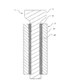
弁棒1の溶接層12は、図2に示すように、母材11と接する第1の溶接層12aと、第1の溶接層12aの上に形成される第2の溶接層12bとから構成される。つまり、母材11に対してプラズマ粉体肉盛り溶接を行うことにより、第1の溶接層12aを形成する。第1の溶接層12aを形成し、その表面を研削、研磨加工した後に、第1の溶接層12aの上にプラズマ粉体肉盛り溶接を行うことにより、第2の溶接層12bを形成する。第2の溶接層12bを形成した後、その表面を研削、研磨加工して、溶接層12を得る。第1の溶接層12aと第2の溶接層12bとは、通常、同一の溶接金属で構成される。
As shown in FIG. 2, the
本実施形態による弁棒1は、第1の溶接層12aの希釈率を5〜25%にする。
第1の溶接層12aの希釈率が5%未満になると、弁棒1の使用環境下において、溶接層12が母材11と第1の溶接層12aとの界面で剥離しやすくなるからである。これは、希釈率が低いと、母材11に対する第1の溶接層12aの間で融合不良などの溶接欠陥が入り、密着強度が低くなるためと解される。実際の溶接工程においては、希釈率の部分的な変動を考慮して、希釈率の下限を10%として管理することが好ましい。
一方、第1の溶接層12aの希釈率が25%を超えると、弁棒1の使用環境下において、第1の溶接層12aに割れが発生しやすくなる。好ましい希釈率は15〜25%、より好ましい希釈率は17〜23%である。希釈率が高いと割れが発生する理由は、以下の通りである。希釈率が高くなると、第1の溶接層12a内に、母材11中のFe成分が多く溶け込むことになる。このFeと上記したCo基合金に含まれるCr成分とが結びつくことにより、σ相が析出しやすい状態となる。ここで、σ相とは、FeとCrの金属間化合物であり、非常に硬く、かつ脆い特性を有している。Fe成分が多く溶け込んだ第1の溶接層12aが長時間高温に保持されることにより、σ相が第1の溶接層12aに析出して割れやすくなる。また、プラズマ粉体肉盛り溶接後に、第1の溶接層12aが常温まで冷却される過程で第1の溶接層12aに引張りの残留応力が生じる。この残留応力は、希釈率の増加に伴い高くなる傾向にある。一方、弁棒1の作動により、第1の溶接層12aには外力が加わる。この外力と残留応力の和が、第1の溶接層12aの破壊強度を超えると割れが発生する。
In the valve stem 1 according to the present embodiment, the dilution rate of the
This is because when the dilution ratio of the
On the other hand, if the dilution ratio of the
次に、第2の溶接層12bは、第1の溶接層12aと同様の溶接金属で構成される。したがって、第1の溶接層12aに対して第2の溶接層12bは高い密着強度を得ることができる。このように高い密着強度を得ることができるため、第2の溶接層12bは比較的低い希釈率を許容し、第1の溶接層12aの50%以下の希釈率とすればよい。より具体的な希釈率としては、5%未満、さらには3%未満とすることができる。なお、第2の溶接層12bの希釈率は、第1の溶接層12aを母材として求めることになる。
Next, the
第1の溶接層12a(第2の溶接層12b)の希釈率は、プラズマ粉体肉盛り溶接の条件により調整することができる。例えば、上記したステライト、トリバロイを溶接金属とする場合、以下の条件とすることにより、第1の溶接層12aによる希釈率を15〜25%にすることができる。
母材11の予熱温度:250〜350℃
溶接速度:70〜80mm/min.
アシストガス:Arガス(温度;20℃)
ガス流量:プラズマガス;2〜3l/min. シールドガス;10〜15l/min.
トーチと溶接部の距離:5〜10mm
トーチ温度:90〜120℃
溶接金属粒度分布:60〜180μmThe dilution rate of the
Preheating temperature of base material 11: 250-350 ° C
Welding speed: 70-80 mm / min.
Assist gas: Ar gas (temperature; 20 ° C)
Gas flow rate: plasma gas; 2-3 l / min. Shielding gas: 10-15 l / min.
Distance between torch and weld: 5-10mm
Torch temperature: 90-120 ° C
Weld metal particle size distribution: 60-180 μm
上記溶接条件には、溶接速度を遅くしているところに特徴がある。これは、15〜25%というプラズマ粉体肉盛り溶接においては、高めの希釈率を得るためである。つまり、溶接速度を遅くすることによって、溶接金属が液相状態となる時間を長くして希釈率を高くするのである。液相状態となる時間を多くすることで、溶接面の波打ちが低減され、表面が平滑な第1の溶接層12aを得ることができる利点もある。The welding condition is characterized in that the welding speed is reduced. This is to obtain a higher dilution rate in the plasma powder overlay welding of 15 to 25%. That is, by reducing the welding speed, the time during which the weld metal is in the liquid phase is lengthened and the dilution rate is increased. By increasing the time for the liquid phase state, there is an advantage that the
第2の溶接層12bは、第1の溶接層12aよりも希釈率は低い。したがって、第1の溶接層12aと同じ装置を使用し、肉盛り溶接層の厚みが同じならば第1の溶接層12aを形成する場合に比べて、溶接速度を70〜100mm/min.の範囲で速くすればよい。他の溶接条件は、第1の溶接層12aと同様とすればよい。
The
第1の溶接層12a、第2の溶接層12bの厚さは、使用環境によって適宜設定されるべきであるが、各々、1.5〜2.0mm程度とすることが好ましい。1層で3〜4mmの厚さの溶接層12を得ようとする場合、後に行う研削、研磨加工の負担を軽減するためにも、溶接ビードの波の高さを抑えて均一な厚さの肉盛りを行うには、熟練者による溶接が必要である。しかるに、第1の溶接層12a、第2の溶接層12bの厚さが1.5〜2.0mm程度と比較的薄い場合には、ロボットでの溶接によっても表面が平滑な溶接面を得ることができる。さらに、第1の溶接層12aの溶接金属と第2の溶接層12bの溶接金属が同じであるため、各々の厚さを1.5〜2.0mm程度と薄くすることができるので、溶接中のガスの巻き込みが少なく、研削による異物滞留の原因となる空孔の発生を低減することができる。
Although the thickness of the
以上では、弁棒1の溶接層12について説明したが、軸受け2の溶接層22についても、同様の形態を有する第1の溶接層、第2の溶接層を設ける。
Although the
コバルト基合金は乾燥摩擦係数が小さく、スケールが発生しないため摩擦係数は安定している。特に、コバルト基合金同士の乾燥摩擦係数は0.56と、コバルト基合金とFe基合金との摩擦係数が0.41であるのに比べて高いが、スケールの発生が皆無であること及び高温蒸気の介在により、実質的に摩擦係数は乾燥時よりも低く安定している。したがって、弁棒1と軸受け2の摺動面にコバルト基合金を配設することにより、より低いトルクで弁の開閉が可能となる。したがって、本発明によれば、弁開閉のためのアクチュエータを小型化できるという効果をも奏する。
Cobalt-based alloys have a low dry friction coefficient and are stable because they do not generate scale. In particular, the dry friction coefficient between cobalt-base alloys is 0.56, which is higher than the friction coefficient between cobalt-base alloys and Fe-base alloys is 0.41, but there is no generation of scale and high temperature. Due to the presence of steam, the coefficient of friction is substantially lower and stable than during drying. Therefore, by disposing the cobalt base alloy on the sliding surfaces of the valve stem 1 and the
1.2%Cr−0.3%Mo鋼(JIS SCM3)を用意した。板状のこの鋼材(母材)に対して、以下の要領でプラズマ粉体肉盛り溶接を行った。なお、プラズマ粉体肉盛り溶接は、図2に示すように、2層とし、かつ希釈率を変えた。希釈率は、図2に示すように、溶接速度を変えることにより調節した。なお、図2において、第1の溶接層とは母材表面に形成したものであり、第2の溶接層とは第1の溶接層の表面に形成したものである。第1の溶接層を形成した後に、その表面を研削、研磨加工することにより図2に示す厚さとした。その後、第2の溶接層を形成した後に、その表面を研削、研磨加工することにより図2に示す厚さとした。 1.2% Cr-0.3% Mo steel (JIS SCM3) was prepared. Plasma powder build-up welding was performed on the plate-shaped steel material (base material) in the following manner. In addition, as shown in FIG. 2, plasma powder build-up welding was made into two layers and the dilution rate was changed. The dilution rate was adjusted by changing the welding speed as shown in FIG. In FIG. 2, the first weld layer is formed on the surface of the base material, and the second weld layer is formed on the surface of the first weld layer. After forming the first weld layer, the surface was ground and polished to a thickness shown in FIG. Then, after forming the second weld layer, the surface was ground and polished to the thickness shown in FIG.
鋼材の予熱温度:300℃
溶接速度:60〜80mm/min.
アシストガス:Arガス(温度;20℃)
ガス流量:プラズマガス;2.5l/min.シールドガス;12l/min.
トーチと溶接部の距離:6mm
トーチ温度:90〜120℃
溶接金属材質:55%Co−30%Cr−15%W(重量%)
溶接金属粒度分布:120μm(平均粒径)Preheating temperature of steel: 300 ° C
Welding speed: 60 to 80 mm / min.
Assist gas: Ar gas (temperature; 20 ° C)
Gas flow rate: plasma gas; 2.5 l / min. Shielding gas: 12 l / min.
Distance between torch and welded part: 6mm
Torch temperature: 90-120 ° C
Weld metal material: 55% Co-30% Cr-15% W (% by weight)
Weld metal particle size distribution: 120 μm (average particle size)
以上の要領で作製された、試料を用いて溶接層の剥離、割れの評価を行った。
剥離の評価は、超音波探傷検査により行った。また、割れの評価は、蛍光浸透探傷検査により行った。
その結果を表2に示すが、第1の溶接層の希釈率が5%未満の場合には、母材から第1の溶接層の剥離が観察された。ただし、第2の溶接層の希釈率が5%未満の場合には、第1の溶接層から第2の溶接層が剥離する事例はなかった。
第1の溶接層の希釈率が25%を超えると、第1の溶接層に割れが観察された。同様に、第2の溶接層の希釈率が25%を超えると、第2の溶接層に割れが観察された。Evaluation of peeling and cracking of the weld layer was performed using the sample prepared as described above.
The evaluation of peeling was performed by ultrasonic flaw detection inspection. Moreover, the evaluation of the crack was performed by the fluorescence penetrant inspection.
The results are shown in Table 2. When the dilution ratio of the first weld layer was less than 5%, peeling of the first weld layer from the base material was observed. However, when the dilution rate of the second weld layer was less than 5%, there was no case where the second weld layer peeled off from the first weld layer.
When the dilution ratio of the first weld layer exceeded 25%, cracks were observed in the first weld layer. Similarly, cracks were observed in the second weld layer when the dilution ratio of the second weld layer exceeded 25%.
以上の結果より、母材に接するプラズマ粉体肉盛り溶接による第1の溶接層の希釈率は、5〜25%の範囲とすることが好ましい。また、第1の溶接層上に形成する第2の溶接層の希釈率は、第2の溶接層を構成するコバルト基合金の本来の特性を引き出すために、5%以下、好ましくは3%以下とする。 From the above results, the dilution rate of the first weld layer by plasma powder build-up welding in contact with the base material is preferably in the range of 5 to 25 % . Also, the dilution ratio of the second weld layer formed on the first weld layer, in order to bring out the inherent characteristics of the cobalt-based alloy constituting the second welding layer, 5% or less, preferably 3% The following.
1…弁棒、11…母材、12…溶接層、12a…第1の溶接層、12b…第2の溶接層
2…軸受け、21…母材、22…溶接層DESCRIPTION OF SYMBOLS 1 ... Valve stem, 11 ... Base material, 12 ... Welded layer, 12a ... 1st welded layer, 12b ... 2nd welded
Claims (2)
前記軸受けには前記弁棒との摺動面に耐熱コバルト基合金からなるプラズマ粉体肉盛り溶接層Xが形成され、かつ、
前記弁棒には前記軸受けとの摺動面に耐熱コバルト基合金からなるプラズマ粉体肉盛り溶接層Yが形成されており、
前記軸受け側に形成された前記溶接層Xは、
前記軸受けの表面に形成された、希釈率が15〜25%の第1の溶接層と、
前記第1の溶接層の上に形成された、希釈率が前記第1の溶接層の希釈率の50%以下である第2の溶接層とを備え、かつ、
前記弁棒側に形成された前記溶接層Yは、
前記弁棒の表面に形成された、希釈率が15〜25%の第3の溶接層と、
前記第3の溶接層の上に形成された、希釈率が前記第3の溶接層の希釈率の50%以下である第4の溶接層とを備えることを特徴とする弁装置。A valve device comprising a bearing having a sliding surface with a valve stem,
The bearing is formed with a plasma powder build-up weld layer X made of a heat-resistant cobalt-based alloy on the sliding surface with the valve stem, and
A plasma powder build-up weld layer Y made of a heat-resistant cobalt base alloy is formed on the sliding surface of the valve stem with the bearing,
The weld layer X formed on the bearing side is:
A first weld layer having a dilution rate of 15 to 25% formed on the surface of the bearing;
A second weld layer formed on the first weld layer and having a dilution rate of 50% or less of the dilution rate of the first weld layer, and
The weld layer Y formed on the valve stem side is
A third weld layer having a dilution rate of 15 to 25% formed on the surface of the valve stem;
And a fourth weld layer formed on the third weld layer and having a dilution rate of 50% or less of the dilution rate of the third weld layer.
Applications Claiming Priority (1)
| Application Number | Priority Date | Filing Date | Title |
|---|---|---|---|
| PCT/JP2007/054803 WO2008111150A1 (en) | 2007-03-12 | 2007-03-12 | Valve gear |
Publications (2)
| Publication Number | Publication Date |
|---|---|
| JPWO2008111150A1 JPWO2008111150A1 (en) | 2010-06-24 |
| JP5101601B2 true JP5101601B2 (en) | 2012-12-19 |
Family
ID=39759101
Family Applications (1)
| Application Number | Title | Priority Date | Filing Date |
|---|---|---|---|
| JP2009503792A Active JP5101601B2 (en) | 2007-03-12 | 2007-03-12 | Valve device |
Country Status (5)
| Country | Link |
|---|---|
| US (1) | US8167270B2 (en) |
| EP (1) | EP2147737A4 (en) |
| JP (1) | JP5101601B2 (en) |
| CN (1) | CN101489711B (en) |
| WO (1) | WO2008111150A1 (en) |
Families Citing this family (9)
| Publication number | Priority date | Publication date | Assignee | Title |
|---|---|---|---|---|
| JP2010084693A (en) * | 2008-10-01 | 2010-04-15 | Aisan Ind Co Ltd | Engine valve |
| JP5320196B2 (en) * | 2009-07-15 | 2013-10-23 | 日立Geニュークリア・エナジー株式会社 | Dissimilar material overlay welding method and dissimilar material overlay welded structure |
| US9816619B2 (en) * | 2011-01-17 | 2017-11-14 | Hamilton Sundstrand Corporation | Thrust plate for butterfly valve |
| US9989496B2 (en) * | 2012-11-29 | 2018-06-05 | Beijing Institute Of Technology | Fixed value residual stress test block and manufacturing and preservation method thereof |
| JP7163009B2 (en) * | 2017-06-26 | 2022-10-31 | 三菱重工業株式会社 | High temperature sliding parts and steam turbines |
| CN108591610B (en) * | 2018-04-27 | 2024-04-23 | 湖南乐准智芯生物科技有限公司 | Microfluidic system, micro valve and control method |
| US11155904B2 (en) | 2019-07-11 | 2021-10-26 | L.E. Jones Company | Cobalt-rich wear resistant alloy and method of making and use thereof |
| CN114160941A (en) * | 2021-11-25 | 2022-03-11 | 沈阳鼓风机集团核电泵业有限公司 | Method for plasma surfacing of cobalt-based alloy in cylindrical inner hole |
| JP2024027367A (en) | 2022-08-17 | 2024-03-01 | 三菱重工業株式会社 | Overlay welding method |
Citations (6)
| Publication number | Priority date | Publication date | Assignee | Title |
|---|---|---|---|---|
| JPS62254976A (en) * | 1986-04-28 | 1987-11-06 | Mitsubishi Electric Corp | Powder plasma building-up method for guide bar |
| JPS62279083A (en) * | 1986-05-29 | 1987-12-03 | Japan Steel Works Ltd:The | Powder plasma padding method |
| JPH04147769A (en) * | 1990-10-12 | 1992-05-21 | Nippon Steel Corp | Build-up welding method by welding for titanium alloy engine valve |
| JPH0671451A (en) * | 1992-08-28 | 1994-03-15 | Hitachi Ltd | Production of shovel |
| JPH06221105A (en) * | 1993-01-28 | 1994-08-09 | Toshiba Corp | Steam valve |
| JP2000117485A (en) * | 1998-10-13 | 2000-04-25 | Mitsubishi Heavy Ind Ltd | Powder material and weld metal for powder plasma cladding by welding |
Family Cites Families (11)
| Publication number | Priority date | Publication date | Assignee | Title |
|---|---|---|---|---|
| NL271417A (en) * | 1960-11-15 | 1900-01-01 | ||
| US3271553A (en) * | 1965-06-24 | 1966-09-06 | Arcos Corp | Overlay welding |
| US4173685A (en) * | 1978-05-23 | 1979-11-06 | Union Carbide Corporation | Coating material and method of applying same for producing wear and corrosion resistant coated articles |
| JPS59169696A (en) | 1983-03-18 | 1984-09-25 | Toshiba Corp | Valve device |
| JPS6017206A (en) | 1983-07-08 | 1985-01-29 | Hitachi Ltd | Steam valve |
| JPH01152091U (en) * | 1988-04-08 | 1989-10-19 | ||
| JPH06174126A (en) | 1992-12-08 | 1994-06-24 | Toshiba Corp | Manufacture of valve spindle |
| US6780458B2 (en) * | 2001-08-01 | 2004-08-24 | Siemens Westinghouse Power Corporation | Wear and erosion resistant alloys applied by cold spray technique |
| JP3886394B2 (en) * | 2002-02-25 | 2007-02-28 | 株式会社荏原製作所 | Covering material with corrosion resistance and wear resistance |
| DE102004060538B3 (en) * | 2004-12-16 | 2006-03-16 | Daimlerchrysler Ag | Firmly adhered hard metal layers on substrates, especially valve seating rings on cylinder heads, produced using adhesion-promoting layer formed by applying plasma jet containing hard metal to substrate |
| CN100526512C (en) * | 2005-12-14 | 2009-08-12 | 东方电气集团东方汽轮机有限公司 | Steam turbine valve manifold stellite alloy plasma spray welding method and equipment |
-
2007
- 2007-03-12 EP EP07738275A patent/EP2147737A4/en not_active Withdrawn
- 2007-03-12 US US12/309,029 patent/US8167270B2/en active Active
- 2007-03-12 CN CN2007800260670A patent/CN101489711B/en active Active
- 2007-03-12 WO PCT/JP2007/054803 patent/WO2008111150A1/en active Application Filing
- 2007-03-12 JP JP2009503792A patent/JP5101601B2/en active Active
Patent Citations (6)
| Publication number | Priority date | Publication date | Assignee | Title |
|---|---|---|---|---|
| JPS62254976A (en) * | 1986-04-28 | 1987-11-06 | Mitsubishi Electric Corp | Powder plasma building-up method for guide bar |
| JPS62279083A (en) * | 1986-05-29 | 1987-12-03 | Japan Steel Works Ltd:The | Powder plasma padding method |
| JPH04147769A (en) * | 1990-10-12 | 1992-05-21 | Nippon Steel Corp | Build-up welding method by welding for titanium alloy engine valve |
| JPH0671451A (en) * | 1992-08-28 | 1994-03-15 | Hitachi Ltd | Production of shovel |
| JPH06221105A (en) * | 1993-01-28 | 1994-08-09 | Toshiba Corp | Steam valve |
| JP2000117485A (en) * | 1998-10-13 | 2000-04-25 | Mitsubishi Heavy Ind Ltd | Powder material and weld metal for powder plasma cladding by welding |
Also Published As
| Publication number | Publication date |
|---|---|
| EP2147737A4 (en) | 2013-02-27 |
| US20100006793A1 (en) | 2010-01-14 |
| EP2147737A1 (en) | 2010-01-27 |
| WO2008111150A1 (en) | 2008-09-18 |
| US8167270B2 (en) | 2012-05-01 |
| CN101489711B (en) | 2012-05-09 |
| CN101489711A (en) | 2009-07-22 |
| JPWO2008111150A1 (en) | 2010-06-24 |
Similar Documents
| Publication | Publication Date | Title |
|---|---|---|
| JP5101601B2 (en) | Valve device | |
| KR101671679B1 (en) | Brake disc and method for producing same | |
| US8703044B2 (en) | Machine components and methods of fabricating and repairing | |
| JP7126870B2 (en) | Methods of welding superalloys | |
| Thawari et al. | Effect of multi-layer laser cladding of Stellite 6 and Inconel 718 materials on clad geometry, microstructure evolution and mechanical properties | |
| Kumar et al. | Some studies on nickel based Inconel 625 hard overlays on AISI 316L plate by gas metal arc welding based hardfacing process | |
| JP4517008B1 (en) | High temperature material conveying member | |
| Váz et al. | Welding and thermal spray processes for maintenance of hydraulic turbine runners: case studies | |
| JPH0778273B2 (en) | Wing member surface treatment method | |
| JP4412563B2 (en) | High temperature material conveying member | |
| Lisiecki et al. | Laser cladding of Co-based metallic powder at cryogenic conditions | |
| US20160146020A1 (en) | BRAZING METHOD FOR REINFORCING THE Z-NOTCH OF TiAl BLADES | |
| JP2005254283A (en) | Method of repairing wear-resistant member | |
| Keshavarz et al. | A Comparison of weldability, structure, and mechanical properties of CM64 and Tribaloy T-800 welds for hard-facing of turbine blades | |
| JP5554192B2 (en) | Co-based hardfacing material and overlaying method | |
| JP2004077408A (en) | Valve for light-water reactor | |
| Deshmukh et al. | Evaluation of surface characteristics of PTAW Hardfacing based on energy and powder supplied | |
| Klimpel et al. | Laser repair hardfacing of titanium alloy turbine | |
| KR20090037428A (en) | Valve gear | |
| JP2007100217A (en) | Roller for conveying hot material | |
| Sahu et al. | Effect of current pulsation on weld microstructure during micro-plasma arc welding of Inconel 718 | |
| Raya et al. | Laser cladding of continuous caster lateral rolls: Microstructure, wear and corrosion characterisation and on-field performance evaluation | |
| Venkataraman et al. | Development of nickel alloy based hardfacing procedure for fast breeder test reactor control rod sheath using conventional gas tungsten arc welding process and metal cored alloy grade ERC Ni Cr–B | |
| JP2006015380A (en) | Alloy for repair-welding of hard build-up welding part and repair-welding method | |
| Türkan et al. | CORROSION AND MECHANICAL BEHAVIOUR OF TIG-WELDED AISI 304L STAINLESS STEEL. |
Legal Events
| Date | Code | Title | Description |
|---|---|---|---|
| A621 | Written request for application examination |
Free format text: JAPANESE INTERMEDIATE CODE: A621 Effective date: 20090107 |
|
| A131 | Notification of reasons for refusal |
Free format text: JAPANESE INTERMEDIATE CODE: A131 Effective date: 20110720 |
|
| A521 | Written amendment |
Free format text: JAPANESE INTERMEDIATE CODE: A523 Effective date: 20110916 |
|
| A521 | Written amendment |
Free format text: JAPANESE INTERMEDIATE CODE: A523 Effective date: 20110916 |
|
| A131 | Notification of reasons for refusal |
Free format text: JAPANESE INTERMEDIATE CODE: A131 Effective date: 20120328 |
|
| A521 | Written amendment |
Free format text: JAPANESE INTERMEDIATE CODE: A523 Effective date: 20120420 |
|
| TRDD | Decision of grant or rejection written | ||
| A01 | Written decision to grant a patent or to grant a registration (utility model) |
Free format text: JAPANESE INTERMEDIATE CODE: A01 Effective date: 20120829 |
|
| A01 | Written decision to grant a patent or to grant a registration (utility model) |
Free format text: JAPANESE INTERMEDIATE CODE: A01 |
|
| A61 | First payment of annual fees (during grant procedure) |
Free format text: JAPANESE INTERMEDIATE CODE: A61 Effective date: 20120926 |
|
| FPAY | Renewal fee payment (event date is renewal date of database) |
Free format text: PAYMENT UNTIL: 20151005 Year of fee payment: 3 |
|
| R151 | Written notification of patent or utility model registration |
Ref document number: 5101601 Country of ref document: JP Free format text: JAPANESE INTERMEDIATE CODE: R151 |
|
| FPAY | Renewal fee payment (event date is renewal date of database) |
Free format text: PAYMENT UNTIL: 20151005 Year of fee payment: 3 |
|
| S111 | Request for change of ownership or part of ownership |
Free format text: JAPANESE INTERMEDIATE CODE: R313111 |
|
| R350 | Written notification of registration of transfer |
Free format text: JAPANESE INTERMEDIATE CODE: R350 |
|
| R250 | Receipt of annual fees |
Free format text: JAPANESE INTERMEDIATE CODE: R250 |
|
| S533 | Written request for registration of change of name |
Free format text: JAPANESE INTERMEDIATE CODE: R313533 |
|
| R350 | Written notification of registration of transfer |
Free format text: JAPANESE INTERMEDIATE CODE: R350 |