JP5100471B2 - Rotary compressor - Google Patents
Rotary compressor Download PDFInfo
- Publication number
- JP5100471B2 JP5100471B2 JP2008089090A JP2008089090A JP5100471B2 JP 5100471 B2 JP5100471 B2 JP 5100471B2 JP 2008089090 A JP2008089090 A JP 2008089090A JP 2008089090 A JP2008089090 A JP 2008089090A JP 5100471 B2 JP5100471 B2 JP 5100471B2
- Authority
- JP
- Japan
- Prior art keywords
- crankshaft
- frame
- rotary compressor
- thrust
- eccentric
- Prior art date
- Legal status (The legal status is an assumption and is not a legal conclusion. Google has not performed a legal analysis and makes no representation as to the accuracy of the status listed.)
- Active
Links
Images


Description
この発明は、冷凍空調装置に用いられるロータリ圧縮機に関するものである。 The present invention relates to a rotary compressor used in a refrigeration air conditioner.
ブレードがピストンから離間しないようにスプリングにより付勢されるロータリ圧縮機において、シリンダへッドの軸受を廃止して、フレームにのみ軸受を形成する、いわゆる片持ち軸受構造を採用すると、フレームに形成された軸受やピストンの内周面に形成された軸受に対するガス圧縮荷重による駆動軸の軸傾斜角が増大してしまう。従って軸受の負荷容量が低下するので油膜が形成されにくくなり、軸受の信頼性は大きく損なわれてしまう課題があった。 In a rotary compressor that is energized by a spring so that the blades are not separated from the piston, if a so-called cantilever bearing structure is adopted in which the bearings of the cylinder head are eliminated and the bearings are formed only on the frame, the frame is formed. The shaft inclination angle of the drive shaft due to the gas compression load on the bearing formed on the inner peripheral surface of the bearing or piston is increased. Therefore, since the load capacity of the bearing is reduced, it is difficult to form an oil film, and the reliability of the bearing is greatly impaired.
そこで、ブレードとピストンを一体化するとともに、ブレードを往復且つ揺動自在に支持するガイド、シリンダの端面開口部を閉塞し駆動軸を回転自在に支持するフレーム、他方の端面開口部を閉塞するシリンダヘッドを備えるとともに、シリンダを扁平化したロータリ圧縮機が提案されている(例えば、特許文献1参照)。
ロータリ圧縮機のクランクシャフトと電動機の回転子には、クランクシャフトの回転により偏芯部に生じる遠心力を打ち消すべくバランスウェイトが設けられている。しかし、各部品の寸法のバラツキや組立時のバラツキが存在するために、完全なバランスをとることはできず、クランクシャフトには振れ回り運動をしようとする力が作用する。 A balance weight is provided on the crankshaft of the rotary compressor and the rotor of the electric motor so as to cancel the centrifugal force generated in the eccentric portion by the rotation of the crankshaft. However, since there is a variation in the dimensions of each component and a variation during assembly, a perfect balance cannot be achieved, and a force for swinging acts on the crankshaft.
従来の片持ち軸受構造のロータリ圧縮機は、上記のように振れ回り運動をしようとするクランクシャフトをシリンダヘッドでその下端面を支持する。そのために、振れ回り運動が大きくなり、圧縮機の振動、騒音が大きくなるという課題があった。 A conventional rotary compressor having a cantilever bearing structure supports the lower end surface of a crankshaft that is about to swing as described above with a cylinder head. For this reason, there has been a problem that the whirling motion is increased and the vibration and noise of the compressor are increased.
また、電動機の固定子と電動機の回転子との高さ方向(軸方向)の中心ズレにより生じる磁気推力を鉛直下方に作用させ、クランクシャフトの下端をシリンダの下側に配置したシリンダヘッドに押し当てて、スラスト支持しているため、スラスト荷重が大きくなり、機械損失が大きくなるという課題があった。 In addition, the magnetic thrust generated by the center deviation in the height direction (axial direction) between the stator of the motor and the rotor of the motor is applied vertically downward, and the lower end of the crankshaft is pushed against the cylinder head disposed below the cylinder. Since the thrust is supported, there is a problem that the thrust load increases and the mechanical loss increases.
また、従来の片持ち軸受構造のロータリ圧縮機は、圧縮機の排除容積を拡大するために、偏芯軸の偏芯量を増大させようとした場合、スラスト軸受面積を確保するためには、偏芯軸の反偏芯側外周がシリンダヘッド内周よりも外側に位置する必要があることが、偏芯量の増加に対する制約となり、圧縮機の排除容積拡大に対する制約となっていた。 Further, in the conventional rotary compressor with a cantilever bearing structure, in order to increase the eccentric amount of the eccentric shaft in order to increase the excluded volume of the compressor, in order to ensure the thrust bearing area, The fact that the outer periphery of the eccentric shaft on the side opposite to the eccentric side needs to be located outside the inner periphery of the cylinder head is a restriction on the increase in the amount of eccentricity and a restriction on the expansion of the excluded volume of the compressor.
この発明は、上記のような課題を解決するためになされたもので、クランクシャフトの振れ回り運動を低減することにより、振動、騒音の小さいロータリ圧縮機を提供することを目的とする。 The present invention has been made to solve the above-described problems, and an object of the present invention is to provide a rotary compressor with low vibration and noise by reducing the swinging motion of the crankshaft.
この発明に係るロータリ圧縮機は、
密閉容器内に、圧縮機構部を下部に、前記圧縮機構部を駆動する電動機を上部に配置し、冷媒を圧縮するロータリ圧縮機において、
前記圧縮機構部は、
前記電動機の駆動力を当該圧縮機構部に伝達し、主軸部と前記主軸部に対し偏芯する偏芯部を有するクランクシャフトと、
前記冷媒を圧縮する圧縮室が形成され、軸方向の両端に開口部を有するシリンダと、
前記クランクシャフトの前記偏芯部に嵌合するローリングピストンと、
前記シリンダの前記一方の開口部を閉塞し、前記クランクシャフトを支持するフレームと、
前記シリンダの前記他方の開口部を閉塞するシリンダヘッドとを備え、
前記電動機は、
固定子と、前記固定子の内側に設けられる回転子とを備え、前記回転子の軸方向中心の位置を、前記固定子の軸方向中心の位置に対して所定量下方にずらして配置し、前記回転子に対し鉛直上方に作用する磁気推力が、前記回転子と前記クランクシャフトとに対し鉛直下方に作用する重力を上回るように構成して、前記クランクシャフトを前記フレームに対して押し付け、前記クランクシャフトをフレームの下端面により支持し、
前記フレームは、前記クランクシャフトのスラスト荷重を、該フレームにより上面側から支持するとともに、
前記クランクシャフトを前記シリンダヘッドで支持することなく、前記クランクシャフトの偏芯部の上端面をフレームの下端面により支持することを特徴とする。
The rotary compressor according to the present invention is
In the rotary container for compressing the refrigerant, the compression mechanism part is disposed in the lower part, the electric motor that drives the compression mechanism part is disposed in the upper part in the sealed container,
The compression mechanism is
A crankshaft having an eccentric portion that transmits the driving force of the electric motor to the compression mechanism portion and is eccentric with respect to the main shaft portion;
A cylinder formed with a compression chamber for compressing the refrigerant, and having openings at both ends in the axial direction;
A rolling piston that fits into the eccentric part of the crankshaft;
A frame for closing the one opening of the cylinder and supporting the crankshaft;
A cylinder head that closes the other opening of the cylinder;
The motor is
A stator and a rotor provided on the inner side of the stator, the axial center position of the rotor is shifted downward by a predetermined amount with respect to the axial center position of the stator, The magnetic thrust acting vertically above the rotor is configured to exceed the gravity acting vertically below the rotor and the crankshaft, and the crankshaft is pressed against the frame, Support the crankshaft by the lower end surface of the frame,
The frame supports the thrust load of the crankshaft from the upper surface side by the frame ,
The upper end surface of the eccentric portion of the crankshaft is supported by the lower end surface of the frame without supporting the crankshaft by the cylinder head .
この発明に係るロータリ圧縮機は、回転子の軸方向中心の位置を、固定子の軸方向中心の位置に対して所定量下方にずらして配置し、回転子に対し鉛直上方に作用する磁気推力が、回転子とクランクシャフトとに対し鉛直下方に作用する重力を上回るように構成することにより、クランクシャフトの振れ回り運動を低減することにより、振動、騒音の小さいロータリ圧縮機を提供することができる。 The rotary compressor according to the present invention is arranged such that the axial center position of the rotor is shifted downward by a predetermined amount with respect to the axial center position of the stator, and the magnetic thrust acting vertically upward with respect to the rotor However, it is possible to provide a rotary compressor with low vibration and noise by reducing the swinging motion of the crankshaft by configuring it so as to exceed the gravity acting vertically downward with respect to the rotor and the crankshaft. it can.
実施の形態1.
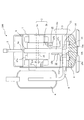
図1、図2は実施の形態1を示す図で、図1はロータリ圧縮機100の縦断面図、図2はクランクシャフト10の振れ回りを示す模式図((a)は本実施の形態、(b)は従来)である。
1 and FIG. 2 are diagrams showing the first embodiment, FIG. 1 is a longitudinal sectional view of the
図1により、ロータリ圧縮機100の構成を説明する。鋼板製の密閉容器1内に、電動機2と圧縮機構部3とが収納固定されている。密閉容器1の底部に、圧縮機構部3を潤滑するための潤滑油4(冷凍機油)が封入されている。
The configuration of the
密閉容器1の上部(上面)に吐出管5が嵌挿され、吐出口5aを形成している。
A
電動機2は、固定子2aと、この固定子2aの内側に設けられる回転子2bとからなる。電動機2は、例えば、ブラシレスDCモータである。
The
回転子2bは、クランクシャフト10の回転により偏芯軸10aに生じる遠心力を打ち消すべくバランスウエイト17a,17bが設けられている。
The
回転子2bの略中心部に駆動軸6が嵌挿され、回転子2bの回転は駆動軸6により圧縮機構部3へ伝達される。
The
また、密閉容器1の外部に吸入マフラ8が設けられる。吸入マフラ8は、密閉容器1内の圧縮機構部3へ吸入管9にて接続されている。
A
圧縮機構部3は、以下に示す要素を備える、所謂ロータリ圧縮機100の形態である。
(1)駆動軸6と同体である、主軸部10cと主軸部10cに対し偏芯する偏芯軸10aを有するクランクシャフト10;
(2)外周が密閉容器1に嵌合し、内部に圧縮室を形成するシリンダ11;
(3)クランクシャフト10が回転自在に嵌挿される軸受部12bと、シリンダ11上端の開口部を閉塞する端板12cとを有するフレーム12;
(4)シリンダ11下端の開口部を閉塞する端板13aを有するシリンダヘッド13;
(5)クランクシャフト10の偏芯軸10aに回転自在に嵌挿され、クランクシャフト10の回転によりシリンダ11内を公転運動するローリングピストン14;
(6)ローリングピストン14の外径に一端が当接したままシリンダ11に設けられた溝内を往復運動する板状のベーン(図示せず)。
The
(1) A
(2) A
(3) A
(4) a
(5) A
(6) A plate-like vane (not shown) that reciprocates in a groove provided in the
ここで、電動機2の回転子2bの軸方向中心16の位置(高さ)を、固定子2aの軸方向中心15の位置(高さ)に対し、所定量(Δd)下方にずらして配置する。
Here, the position (height) of the
これにより、回転子2bと固定子2aの中心のΔdのズレにより、回転子2bに対し鉛直上方に作用する磁気推力が発生する。そして、この磁気推力が、回転子2bとクランクシャフト10とに対し鉛直下方に作用する重力を上回り、クランクシャフト10をフレーム12に対して押し付ける力が作用するようにΔdを選ぶ。
As a result, a magnetic thrust acting vertically upward on the
クランクシャフト10の偏芯軸10aの上端面がフレーム12の下端面により支持され、スラスト軸受12aを形成している。
The upper end surface of the
以上のように、クランクシャフト10を、偏芯軸10aに対し上面側からスラスト軸受12aにより支持する構成とすることにより、従来の偏芯軸10a下端でスラスト支持するような構成に対し、図2に示すようにクランクシャフト10の振れ回りを抑制することができ、ロータリ圧縮機100の振動、騒音を低減することができる。
As described above, the configuration in which the
図2(a)は本実施の形態のロータリ圧縮機100のクランクシャフト10の振れ回りを示す模式図、図2(b)は比較のために示す従来のロータリ圧縮機100のクランクシャフト10の振れ回りを示す模式図である。尚、図2の矢印はバランスウエイト17a,17b及び偏芯軸10aに作用する遠心力を示している。
FIG. 2A is a schematic view showing the swing of the
図2(a)に示すように、本実施の形態のロータリ圧縮機100は、クランクシャフト10を、偏芯軸10aに対し上面側からスラスト軸受12aにより支持する。
As shown in FIG. 2A, the
それに対し、従来のロータリ圧縮機100は、図2(b)に示すように、振れ回り運動をしようとするクランクシャフト10の下端面をシリンダヘッド13で支持する。
On the other hand, as shown in FIG. 2B, the conventional
従って、本実施の形態のロータリ圧縮機100は、従来のロータリ圧縮機100に比べ、クランクシャフト10の振れ回りを抑制することができ、ロータリ圧縮機100の振動、騒音を低減することができる。
Therefore, the
また、本実施の形態のロータリ圧縮機100のクランクシャフト10のスラスト軸受12aに加わるスラスト荷重は、
本実施の形態のスラスト荷重=電動機2の磁気推力 −クランクシャフト10と回転子2bとに加わる重力
となる。
The thrust load applied to the thrust bearing 12a of the
Thrust load of the present embodiment = magnetic thrust of the
従来の鉛直下向きに磁気推力を作用させているロータリ圧縮機100のクランクシャフト10のスラスト軸受12aに加わるスラスト荷重は、
従来のスラスト荷重=電動機2の磁気推力 +クランクシャフト10と回転子2bとに加わる重力
となる。
The thrust load applied to the thrust bearing 12a of the
Conventional thrust load = magnetic thrust of the
本実施の形態のロータリ圧縮機100のクランクシャフト10のスラスト軸受12aに加わるスラスト荷重は、従来の鉛直下向きに磁気推力を作用させているロータリ圧縮機100のクランクシャフト10のスラスト軸受12aに加わるスラスト荷重に比べて低減されることにより、圧縮機構部3の機械損失の低減が可能になる。
The thrust load applied to the thrust bearing 12a of the
また、クランクシャフト10よりスラスト軸受12aに加わる荷重が低減されたため、スラスト軸受12aの摺動面積を低減する事が可能になり、さらに圧縮機構部3の機械損失の低減が可能になる。
Further, since the load applied to the thrust bearing 12a from the
また、従来の片持ち軸受構造のロータリ圧縮機100のように、クランクシャフト10のスラスト荷重を下端面で支持するような構造においては、クランクシャフト10の安定性を確保するために偏芯軸10aの反偏芯側の外周がシリンダヘッド13の内周13bよりも、外側に位置している必要がある。
Further, in a structure in which the thrust load of the
本実施の形態のロータリ圧縮機100は、クランクシャフト10を、偏芯軸10aに対し上面側からスラスト軸受12aにより支持する構造としたことにより、偏芯軸10aの反偏芯側外周がシリンダヘッド13内周よりも外側に位置する必要がなくなる。偏芯量の増加に対する制約が少なくなり、偏芯軸10aの偏芯量を増加させて、クランクシャフト10の偏芯軸10aの反偏芯側の外周が、クランクシャフト10の主軸部10c外周より、内側に位置する場合でも、クランクシャフト10の挙動を安定させることが可能になり、ロータリ圧縮機100の排除容積拡大を容易に行うことができる。
The
尚、偏芯軸10aの反偏芯側外周がクランクシャフトの主軸部10cの外周より内側に位置することとしたが、振動・騒音の低減を要する場合には、偏芯軸10aの反偏芯側外周がクランクシャフトの主軸部10cの外周より、外側に位置するように構成する。このように構成することで偏芯軸10aの全周にわたってスラスト軸受12aにより支持されるためクランクシャフト10の挙動を安定させることができる。
The outer periphery of the
また、クランクシャフト10の短軸を廃止し、クランクシャフト10を偏芯軸10aに対し上面側からスラスト軸受12aにより支持する構造としたことにより、偏芯量を同一とした場合に偏芯軸10aの外径を縮小させる事が可能になり、偏芯軸10a部の機械損失を低減する事が可能になる。
Further, the short shaft of the
以上のように、本実施の形態のロータリ圧縮機100は、電動機2の回転子2bの軸方向中心16の位置を、固定子2aの軸方向中心15の位置に対し、所定量(Δd)下方に位置させることにより、回転子2bに対し鉛直上方に作用する磁気推力が発生し、この磁気推力が回転子2bとクランクシャフト10とに対し鉛直下方に作用する重力を上回るようにしたので、従来のロータリ圧縮機100に比べ、クランクシャフト10の振れ回りを抑制することができ、ロータリ圧縮機100の振動、騒音を低減することができる。
As described above, in the
また、本実施の形態のロータリ圧縮機100のクランクシャフト10のスラスト軸受12aに加わるスラスト荷重は、従来の鉛直下向きに磁気推力を作用させているロータリ圧縮機100のクランクシャフト10のスラスト軸受12aに加わるスラスト荷重に比べて低減されることにより、圧縮機構部3の機械損失の低減が可能になる。
Further, the thrust load applied to the thrust bearing 12a of the
また、クランクシャフト10よりスラスト軸受12aに加わる荷重が低減されたため、スラスト軸受12aの摺動面積を低減する事が可能になり、さらに圧縮機構部3の機械損失の低減が可能になる。
Further, since the load applied to the thrust bearing 12a from the
また、クランクシャフト10を、偏芯軸10aに対し上面側からスラスト軸受12aにより支持する構造としたことにより、偏芯量の増加に対する制約が少なくなり、偏芯軸10aの偏芯量を増加させて、クランクシャフト10の偏芯軸10aの反偏芯側の外周が、クランクシャフト10の主軸部10c外周より内側に位置する場合でも、クランクシャフト10の挙動を安定させることが可能になり、ロータリ圧縮機100の排除容積拡大を容易に行うことができる。
Further, since the
また、クランクシャフト10の短軸を廃止し、クランクシャフト10を偏芯軸10aに対し上面側からスラスト軸受12aにより支持する構造としたことにより、偏芯量を同一とした場合に偏芯軸10aの外径を縮小させる事が可能になり、偏芯軸10a部の機械損失を低減する事が可能になる。
Further, the short shaft of the
実施の形態2.
図3は実施の形態2を示す図で、ロータリ圧縮機100の圧縮機構部3付近の縦断面図である。
FIG. 3 is a view showing the second embodiment, and is a longitudinal sectional view of the vicinity of the
本実施の形態では、クランクシャフト10とフレーム12のスラスト軸受12aとの間に、スラスト受け部材20を嵌挿している。
In the present embodiment, a
スラスト受け部材20は、薄板で略リング状である。スラスト受け部材20の材料は、クランクシャフト10及びフレーム12よりも硬度が十分に大きいばね鋼材等である。
The
スラスト受け部材20は、フレーム12のスラスト軸受12aに設ける。突起と孔等により、スラスト受け部材20の回り止めを行う。
The
図3に示すように、クランクシャフト10とフレーム12のスラスト軸受12aとの間に、薄板状のスラスト受け部材20を嵌挿することにより、スラスト荷重による機械損失を低減することが可能になり、より効率の高いロータリ圧縮機100を得ることができる。
As shown in FIG. 3, by inserting a thin plate-like
また、クランクシャフト10とフレーム12のスラスト軸受12aとの間に、スラスト受け部材20を嵌挿することにより、クランクシャフト10のスラスト面の摩耗を低減することが可能になり、より信頼性の高いロータリ圧縮機100を得ることができる。
Further, by inserting the
尚、クランクシャフト10とフレーム12のスラスト軸受12aとの間に、別体のスラスト受け部材20を嵌挿する例を示したが、偏芯軸10aの反偏芯側外周がクランクシャフト10の主軸部10cの外周より内側に位置する場合は、スラスト受け部材20をフレーム12と一体に設けるとよい。
Although an example in which a separate
スラスト受け部材20をフレーム12と別体に設けると負荷に耐えられずスラスト受け部材20が変形、分離等して振れ回りが発生し、振動・騒音の原因となる可能性があるが、スラスト受け部材20をフレーム12と一体に設けることにより係る可能性を低減することができる。
If the
以上のように、本実施の形態によれば、クランクシャフト10とフレーム12のスラスト軸受12aとの間に、クランクシャフト10及びフレーム12よりも硬度が十分に大きい、ばね鋼材などの薄板状のスラスト受け部材20を嵌挿することにより、スラスト荷重による機械損失を低減することが可能になり、より効率の高いロータリ圧縮機100を得ることができる。
As described above, according to the present embodiment, a thin plate-like thrust, such as a spring steel material, having a hardness sufficiently higher than that of the
また、クランクシャフト10とフレーム12のスラスト軸受12aとの間に、スラスト受け部材20を嵌挿することにより、クランクシャフト10のスラスト面の摩耗を低減することが可能になり、より信頼性の高いロータリ圧縮機100を得ることができる。
Further, by inserting the
1 密閉容器、2 電動機、2a 固定子、2b 回転子、3 圧縮機構部、4 潤滑油、5 吐出管、5a 吐出口、6 駆動軸、8 吸入マフラ、9 吸入管、10 クランクシャフト、10a 偏芯軸、10c 主軸部、11 シリンダ、12 フレーム、12a スラスト軸受、12b 軸受部、12c 端板、13 シリンダヘッド、13a 端板、13b 内周、14 ローリングピストン、15 固定子2aの軸方向中心、16 回転子2bの軸方向中心、17a バランスウエイト、17b バランスウエイト、20 スラスト受け部材、100 ロータリ圧縮機。
DESCRIPTION OF
Claims (3)
前記圧縮機構部は、
前記電動機の駆動力を当該圧縮機構部に伝達し、主軸部と前記主軸部に対し偏芯する偏芯部を有するクランクシャフトと、
前記冷媒を圧縮する圧縮室が形成され、軸方向の両端に開口部を有するシリンダと、
前記クランクシャフトの前記偏芯部に嵌合するローリングピストンと、
前記シリンダの前記一方の開口部を閉塞し、前記クランクシャフトを支持するフレームと、
前記シリンダの前記他方の開口部を閉塞するシリンダヘッドとを備え、
前記電動機は、
固定子と、前記固定子の内側に設けられる回転子とを備え、前記回転子の軸方向中心の位置を、前記固定子の軸方向中心の位置に対して所定量下方にずらして配置し、前記回転子に対し鉛直上方に作用する磁気推力が、前記回転子と前記クランクシャフトとに対し鉛直下方に作用する重力を上回るように構成して、前記クランクシャフトを前記フレームに対して押し付け、前記クランクシャフトをフレームの下端面により支持し、
前記フレームは、前記クランクシャフトのスラスト荷重を、該フレームにより上面側から支持するとともに、
前記クランクシャフトを前記シリンダヘッドで支持することなく、前記クランクシャフトの偏芯部の上端面をフレームの下端面により支持することを特徴とするロータリ圧縮機。 In the rotary container for compressing the refrigerant, the compression mechanism part is disposed in the lower part, the electric motor that drives the compression mechanism part is disposed in the upper part in the sealed container,
The compression mechanism is
A crankshaft having an eccentric portion that transmits the driving force of the electric motor to the compression mechanism portion and is eccentric with respect to the main shaft portion;
A cylinder formed with a compression chamber for compressing the refrigerant, and having openings at both ends in the axial direction;
A rolling piston that fits into the eccentric part of the crankshaft;
A frame for closing the one opening of the cylinder and supporting the crankshaft;
A cylinder head that closes the other opening of the cylinder;
The motor is
A stator and a rotor provided on the inner side of the stator, the axial center position of the rotor is shifted downward by a predetermined amount with respect to the axial center position of the stator, The magnetic thrust acting vertically above the rotor is configured to exceed the gravity acting vertically below the rotor and the crankshaft, and the crankshaft is pressed against the frame, Support the crankshaft by the lower end surface of the frame,
The frame supports the thrust load of the crankshaft from the upper surface side by the frame ,
A rotary compressor characterized in that an upper end surface of an eccentric portion of the crankshaft is supported by a lower end surface of a frame without supporting the crankshaft by the cylinder head .
Priority Applications (1)
| Application Number | Priority Date | Filing Date | Title |
|---|---|---|---|
| JP2008089090A JP5100471B2 (en) | 2008-03-31 | 2008-03-31 | Rotary compressor |
Applications Claiming Priority (1)
| Application Number | Priority Date | Filing Date | Title |
|---|---|---|---|
| JP2008089090A JP5100471B2 (en) | 2008-03-31 | 2008-03-31 | Rotary compressor |
Publications (2)
| Publication Number | Publication Date |
|---|---|
| JP2009243317A JP2009243317A (en) | 2009-10-22 |
| JP5100471B2 true JP5100471B2 (en) | 2012-12-19 |
Family
ID=41305506
Family Applications (1)
| Application Number | Title | Priority Date | Filing Date |
|---|---|---|---|
| JP2008089090A Active JP5100471B2 (en) | 2008-03-31 | 2008-03-31 | Rotary compressor |
Country Status (1)
| Country | Link |
|---|---|
| JP (1) | JP5100471B2 (en) |
Cited By (1)
| Publication number | Priority date | Publication date | Assignee | Title |
|---|---|---|---|---|
| US9360784B2 (en) | 2014-01-09 | 2016-06-07 | Samsung Electronics Co., Ltd. | Magenta toner for developing electrostatic latent images |
Families Citing this family (1)
| Publication number | Priority date | Publication date | Assignee | Title |
|---|---|---|---|---|
| JP2023034613A (en) | 2021-08-31 | 2023-03-13 | 株式会社東芝 | Compressor, and air conditioner |
Family Cites Families (4)
| Publication number | Priority date | Publication date | Assignee | Title |
|---|---|---|---|---|
| JPS48114306U (en) * | 1972-04-03 | 1973-12-27 | ||
| JPS62223477A (en) * | 1986-03-24 | 1987-10-01 | Toshiba Corp | Compressor |
| JPH10159771A (en) * | 1996-12-04 | 1998-06-16 | Matsushita Refrig Co Ltd | Rotary compressor and cooling system |
| JP2001140773A (en) * | 1999-11-18 | 2001-05-22 | Mitsubishi Electric Corp | Rotary compressor |
-
2008
- 2008-03-31 JP JP2008089090A patent/JP5100471B2/en active Active
Cited By (1)
| Publication number | Priority date | Publication date | Assignee | Title |
|---|---|---|---|---|
| US9360784B2 (en) | 2014-01-09 | 2016-06-07 | Samsung Electronics Co., Ltd. | Magenta toner for developing electrostatic latent images |
Also Published As
| Publication number | Publication date |
|---|---|
| JP2009243317A (en) | 2009-10-22 |
Similar Documents
| Publication | Publication Date | Title |
|---|---|---|
| EP2390507B1 (en) | Shaft bearing clearances for an hermetic compressor | |
| KR20110114367A (en) | Hermetic compressor | |
| US9145890B2 (en) | Rotary compressor with dual eccentric portion | |
| JP5066009B2 (en) | Electric compressor | |
| KR20140142046A (en) | Scroll compressor | |
| JP5100471B2 (en) | Rotary compressor | |
| AU2016339431B2 (en) | Compressor | |
| WO2015155802A1 (en) | Scroll compressor | |
| JP6745913B2 (en) | Compressor | |
| JP6351749B2 (en) | Scroll compressor | |
| JP4792947B2 (en) | Compressor | |
| JP6607971B2 (en) | Manufacturing method of rotary compressor | |
| JP6429987B2 (en) | Rotary compressor | |
| KR101711540B1 (en) | Hermetic compressor | |
| KR101698086B1 (en) | Hermetic compressor | |
| JP4356375B2 (en) | Compressor | |
| JP2009074464A (en) | Compressor | |
| KR101738460B1 (en) | Hermetic compressor | |
| JP6650690B2 (en) | Hermetic compressor | |
| JP6675480B2 (en) | Scroll compressor | |
| JP2017014992A (en) | Hermetic compressor | |
| KR20230080885A (en) | Reciprocating compressor | |
| KR101698085B1 (en) | Hermetic compressor | |
| JP2020007928A (en) | Scroll compressor | |
| JPH07233794A (en) | Horizontal rotary compressor |
Legal Events
| Date | Code | Title | Description |
|---|---|---|---|
| A621 | Written request for application examination |
Free format text: JAPANESE INTERMEDIATE CODE: A621 Effective date: 20100526 |
|
| A131 | Notification of reasons for refusal |
Free format text: JAPANESE INTERMEDIATE CODE: A131 Effective date: 20120117 |
|
| A977 | Report on retrieval |
Free format text: JAPANESE INTERMEDIATE CODE: A971007 Effective date: 20120119 |
|
| A521 | Written amendment |
Free format text: JAPANESE INTERMEDIATE CODE: A523 Effective date: 20120127 |
|
| A131 | Notification of reasons for refusal |
Free format text: JAPANESE INTERMEDIATE CODE: A131 Effective date: 20120724 |
|
| A521 | Written amendment |
Free format text: JAPANESE INTERMEDIATE CODE: A523 Effective date: 20120806 |
|
| TRDD | Decision of grant or rejection written | ||
| A01 | Written decision to grant a patent or to grant a registration (utility model) |
Free format text: JAPANESE INTERMEDIATE CODE: A01 Effective date: 20120828 |
|
| A01 | Written decision to grant a patent or to grant a registration (utility model) |
Free format text: JAPANESE INTERMEDIATE CODE: A01 |
|
| A61 | First payment of annual fees (during grant procedure) |
Free format text: JAPANESE INTERMEDIATE CODE: A61 Effective date: 20120925 |
|
| FPAY | Renewal fee payment (event date is renewal date of database) |
Free format text: PAYMENT UNTIL: 20151005 Year of fee payment: 3 |
|
| R150 | Certificate of patent or registration of utility model |
Ref document number: 5100471 Country of ref document: JP Free format text: JAPANESE INTERMEDIATE CODE: R150 Free format text: JAPANESE INTERMEDIATE CODE: R150 |
|
| R250 | Receipt of annual fees |
Free format text: JAPANESE INTERMEDIATE CODE: R250 |
|
| R250 | Receipt of annual fees |
Free format text: JAPANESE INTERMEDIATE CODE: R250 |
|
| R250 | Receipt of annual fees |
Free format text: JAPANESE INTERMEDIATE CODE: R250 |
|
| R250 | Receipt of annual fees |
Free format text: JAPANESE INTERMEDIATE CODE: R250 |
|
| R250 | Receipt of annual fees |
Free format text: JAPANESE INTERMEDIATE CODE: R250 |
|
| R250 | Receipt of annual fees |
Free format text: JAPANESE INTERMEDIATE CODE: R250 |
|
| R250 | Receipt of annual fees |
Free format text: JAPANESE INTERMEDIATE CODE: R250 |
|
| R250 | Receipt of annual fees |
Free format text: JAPANESE INTERMEDIATE CODE: R250 |