JP5098016B2 - Pulp supply equipment for used paper recycling equipment - Google Patents
Pulp supply equipment for used paper recycling equipment Download PDFInfo
- Publication number
- JP5098016B2 JP5098016B2 JP2007010904A JP2007010904A JP5098016B2 JP 5098016 B2 JP5098016 B2 JP 5098016B2 JP 2007010904 A JP2007010904 A JP 2007010904A JP 2007010904 A JP2007010904 A JP 2007010904A JP 5098016 B2 JP5098016 B2 JP 5098016B2
- Authority
- JP
- Japan
- Prior art keywords
- pulp
- paper
- mesh belt
- making
- papermaking
- Prior art date
- Legal status (The legal status is an assumption and is not a legal conclusion. Google has not performed a legal analysis and makes no representation as to the accuracy of the status listed.)
- Expired - Fee Related
Links
Images


Classifications
-
- D—TEXTILES; PAPER
- D21—PAPER-MAKING; PRODUCTION OF CELLULOSE
- D21B—FIBROUS RAW MATERIALS OR THEIR MECHANICAL TREATMENT
- D21B1/00—Fibrous raw materials or their mechanical treatment
- D21B1/04—Fibrous raw materials or their mechanical treatment by dividing raw materials into small particles, e.g. fibres
- D21B1/12—Fibrous raw materials or their mechanical treatment by dividing raw materials into small particles, e.g. fibres by wet methods, by the use of steam
- D21B1/30—Defibrating by other means
- D21B1/32—Defibrating by other means of waste paper
-
- D—TEXTILES; PAPER
- D21—PAPER-MAKING; PRODUCTION OF CELLULOSE
- D21C—PRODUCTION OF CELLULOSE BY REMOVING NON-CELLULOSE SUBSTANCES FROM CELLULOSE-CONTAINING MATERIALS; REGENERATION OF PULPING LIQUORS; APPARATUS THEREFOR
- D21C5/00—Other processes for obtaining cellulose, e.g. cooking cotton linters ; Processes characterised by the choice of cellulose-containing starting materials
- D21C5/02—Working-up waste paper
-
- D—TEXTILES; PAPER
- D21—PAPER-MAKING; PRODUCTION OF CELLULOSE
- D21C—PRODUCTION OF CELLULOSE BY REMOVING NON-CELLULOSE SUBSTANCES FROM CELLULOSE-CONTAINING MATERIALS; REGENERATION OF PULPING LIQUORS; APPARATUS THEREFOR
- D21C7/00—Digesters
- D21C7/06—Feeding devices
-
- D—TEXTILES; PAPER
- D21—PAPER-MAKING; PRODUCTION OF CELLULOSE
- D21F—PAPER-MAKING MACHINES; METHODS OF PRODUCING PAPER THEREON
- D21F9/00—Complete machines for making continuous webs of paper
-
- D—TEXTILES; PAPER
- D21—PAPER-MAKING; PRODUCTION OF CELLULOSE
- D21F—PAPER-MAKING MACHINES; METHODS OF PRODUCING PAPER THEREON
- D21F9/00—Complete machines for making continuous webs of paper
- D21F9/02—Complete machines for making continuous webs of paper of the Fourdrinier type
-
- Y—GENERAL TAGGING OF NEW TECHNOLOGICAL DEVELOPMENTS; GENERAL TAGGING OF CROSS-SECTIONAL TECHNOLOGIES SPANNING OVER SEVERAL SECTIONS OF THE IPC; TECHNICAL SUBJECTS COVERED BY FORMER USPC CROSS-REFERENCE ART COLLECTIONS [XRACs] AND DIGESTS
- Y02—TECHNOLOGIES OR APPLICATIONS FOR MITIGATION OR ADAPTATION AGAINST CLIMATE CHANGE
- Y02W—CLIMATE CHANGE MITIGATION TECHNOLOGIES RELATED TO WASTEWATER TREATMENT OR WASTE MANAGEMENT
- Y02W30/00—Technologies for solid waste management
- Y02W30/50—Reuse, recycling or recovery technologies
- Y02W30/64—Paper recycling
Abstract
Description
本発明は古紙再生装置のパルプ供給装置に関し、さらに詳細には、古紙が発生する場所に配置されて、発生する古紙を廃棄処分することなく、その場で再利用可能な紙に再生処理する什器サイズの小型古紙再生装置において、スラリー状のパルプ懸濁液を抄いて湿紙とする抄紙部の主要部を構成するパルプ供給装置に関する。 The present invention relates to a pulp supply device for used paper recycling apparatus, and more particularly, a container that is disposed in a place where used paper is generated and recycles the generated used paper into paper that can be reused on the spot without being disposed of. The present invention relates to a pulp supply apparatus that constitutes a main part of a paper making section that makes wet paper by making a slurry-like pulp suspension in a small-sized waste paper recycling apparatus.
官公庁や一般企業等の各種事業所の日常業務はもちろんのこと、一般家庭の日常生活においても、使用済みや不要となった各種書類いわゆる古紙が発生している。これらの古紙は、ゴミとして廃棄されたり、焼却されたりして、廃棄処分されることになる。 In addition to daily work at various offices such as government offices and general enterprises, various types of used paper, so-called waste paper, are generated in daily life of ordinary households. These waste papers are discarded as trash or incinerated for disposal.
一方、限りある地球資源の有効利用という機運の世界的な高まりのなかで、近時、廃棄処分されてきた古紙を、廃棄処分することなく再生利用するための技術が種々開発されている。 On the other hand, various technologies for reclaiming waste paper that has been disposed of recently without being disposed of have been developed in the global increase in the momentum of effective utilization of limited earth resources.
これらの古紙再生技術は、ほとんどが製紙業界において採用実施されており、その古紙再生設備には、通常の製紙設備同様、再生紙の高速大量生産と高品質化を目的として、広大な敷地、莫大な投資、および紙抄きに使われる大量の水や薬品などが必要とされる。 Most of these recycled paper recycling technologies are adopted and implemented in the paper industry. Like the normal papermaking equipment, the used paper recycling equipment has a vast site, enormous volume for the purpose of high-speed mass production and high quality of recycled paper. Investment, and a large amount of water and chemicals used for papermaking.
また、古紙再生にあっては多くの人手による古紙回収作業が必要であり、しかも、この古紙回収には、多人数による異物混入、古紙再生紙への知識不足による分別不良、忌避品の除去不足などの問題があり、せっかく古紙を回収しても、これらの古紙を100%再生紙として再生するには、専門業者による再度の選別や洗浄等の作業を余儀なくされている。さらに、極秘文書などの古紙は、機密上の問題から古紙回収には簡単に出されることはなく、焼却処分されてしまうため、リサイクル化が進んでいない。 In addition, waste paper recycling requires a lot of manual waste paper collection work, and this waste paper collection involves the mixing of foreign substances by many people, poor sorting due to insufficient knowledge of recycled paper, and insufficient removal of repellents. However, even if waste paper is collected, in order to recycle these waste paper as 100% recycled paper, work such as re-sorting and washing by a specialist is required. Furthermore, waste paper such as top-secret documents is not easily collected for waste paper collection due to confidentiality issues and is incinerated, so recycling is not progressing.
これらの古紙回収の問題を解決するには、古紙発生元において自前で再生利用することができるような技術の開発が有効であり、この観点から特許文献1に記載されるような装置が開発提案されている。
In order to solve these waste paper collection problems, it is effective to develop a technology that can be recycled and used by the waste paper generation source. From this viewpoint, an apparatus as described in
この装置は、少量の水を加えながら古紙を少しずつ引きちぎり細かく裁断する方式の湿式シュレッダであり、このシュレッダにより裁断処理された裁断屑は社外の古紙再生工場等へ送られて、再生紙の原料として再利用されている。 This device is a wet shredder that cuts waste paper little by little while adding a small amount of water, and the cutting waste cut by this shredder is sent to an external waste paper recycling factory, etc. Reused as raw material.
この湿式シュレッダによる裁断屑はパルプ化されて紙片の形態を留めていないので、高い機密性を保持することができ、極秘文書などの古紙のリサイクル化を促進するという効果が期待できる。 Since the cutting waste produced by the wet shredder is pulped and does not retain the form of a piece of paper, high confidentiality can be maintained, and an effect of promoting recycling of used paper such as top secret documents can be expected.
しかしながら、この湿式シュレッダは、かなり大型の装置で、大きな設置スペースを必要とすることから、多量の古紙が発生する大きな事業所等においてのみ使用可能なものであり、大きな設置スペースがなく、発生する古紙も少量であるような小規模店舗や個人事務所、あるいは一般家庭には不向きないしは使用不可能であった。しかも、裁断処理された裁断屑は再生紙の原料として再利用されるといっても、古紙再生工場等の大規模工場でのみ処理可能なもので、紙再生のためのコストも高くつき、不経済であった。 However, since this wet shredder is a fairly large device and requires a large installation space, it can be used only in large establishments where a large amount of waste paper is generated and does not have a large installation space. It was unsuitable or unusable for small-scale stores, private offices, or ordinary households where small amounts of waste paper were used. In addition, even though the cut scraps that have been cut can be reused as raw materials for recycled paper, they can only be processed at large-scale factories such as used paper recycling factories. It was an economy.
本発明はかかる従来の問題点に鑑みてなされたものであって、その目的とするところは、大きな事業所等だけでなく、小規模店舗や一般家庭などの室内にも設置可能であるとともに、環境に優しくかつランニングコストも低く抑えることができ、しかも、機密情報や個人情報など各種情報の漏洩・流出を確実に防止できて、高い機密性を保持することができる什器サイズの古紙再生装置を実現するパルプ供給装置を提供することにある。 The present invention has been made in view of such conventional problems, and the purpose thereof is not only a large business office, but also can be installed in a room such as a small store or a general household, A furniture-sized recycled paper recycling device that is environmentally friendly and can keep running costs low, and that can reliably prevent the leakage and outflow of various types of information such as confidential information and personal information, while maintaining high confidentiality. It is in providing the pulp supply apparatus which implement | achieves.
また、本発明の他の目的とするところは、上記パルプ供給装置を備えた抄紙装置を提供することにある。 Another object of the present invention is to provide a papermaking apparatus provided with the above pulp supply apparatus.
さらに、本発明の他の目的とするところは、上記抄紙装置を備えた古紙再生装置を提供することにある。 Furthermore, another object of the present invention is to provide a used paper recycling apparatus provided with the paper making apparatus.
この目的を達成するため、本発明のパルプ供給装置は、古紙が発生する場所に配置可能な什器サイズの古紙再生装置において、前工程のパルプ製造部で製造された古紙パルプを抄紙して再生紙を製造する抄紙装置のパルプ供給部を構成する装置であって、上記抄紙装置において走行方向へ向けて上向き傾斜状に配置されて走行する無端網状ベルトの下面に摺接可能に配設された仕切り部材と、上記無端網状ベルトの上面に摺接可能に配設されるとともに、上記パルプ製造部から送られてくる水と古紙パルプが共存するスラリー状のパルプ懸濁液の供給幅を規定する抄き枠体とを備え、上記抄き枠体内に、供給された上記パルプ懸濁液の均等な分散を促す曲がりくねった流通路と、この流通路の上流側に設けられて、滞留される上記パルプ懸濁液の水位を一定に維持するオーバフロー堰とが設けられ、上記抄き枠体内に供給された上記パルプ懸濁液が、上記曲がりくねった流通路を通過した後に上記オーバフロー堰により規定される一定水位まで滞留し、上記走行する上記無端網状ベルト上面に均一に拡散して供給されることを特徴とする。 In order to achieve this object, the pulp supply apparatus of the present invention is a paper-sized paper recycling apparatus that can be placed at a place where used paper is generated. A pulp supply unit of a papermaking apparatus for manufacturing the papermaking apparatus, wherein the partition is disposed so as to be slidable on the lower surface of the endless mesh belt that is disposed in an upwardly inclined manner in the traveling direction in the papermaking apparatus. A paper and a paper which is disposed so as to be slidable on the upper surface of the member and the endless mesh belt and which defines a supply width of a slurry-like pulp suspension in which water sent from the pulp manufacturing unit and waste paper pulp coexist. A winding flow path that encourages even dispersion of the supplied pulp suspension, and the pulp that is provided and retained on the upstream side of the flow path. Suspension Provided and overflow weir to maintain the water level constant is, the paper making frame the pulp suspension supplied in the body, retention to a certain level defined by the overflow gate after passing through the flow passage meandering above The upper end of the traveling endless mesh belt is uniformly diffused and supplied.
好適な実施態様として、以下の構成が採用される。
(1)上記抄き枠体内に上下方向へ曲がりくねった上記流通路が設けられるとともに、この流通路の出口側部位に、上記網状ベルトの網目を上側から閉塞状態に被覆する平板部材が設けられ、上記抄き枠体内に供給された上記パルプ懸濁液が、上記曲がりくねった流通路を通過した後に上記オーバフロー堰により規定される一定水位まで滞留し、これにより、走行方向へ向けて上向き傾斜状に配置されて走行する上記無端網状ベルト上面に均一に拡散して供給される。
The following configuration is adopted as a preferred embodiment.
( 1 ) The flow path that winds in the vertical direction is provided in the paper making frame body, and a flat plate member that covers the mesh of the mesh belt from the upper side to the closed state is provided at an exit side portion of the flow path, The pulp suspension supplied into the papermaking frame stays up to a certain water level defined by the overflow weir after passing through the tortuous flow passage, and thereby inclines upward in the running direction. It is supplied by being uniformly diffused on the upper surface of the endless mesh belt which is disposed and travels.
(2)上記仕切り部材は、上記網状ベルトの下面を摺接支持するスノコ構造とされる。 ( 2 ) The partition member has a slat structure that slidably supports the lower surface of the mesh belt.
(3)上記流通路は、上記抄き枠体内に設けられた複数の堰部材により形成されている。 ( 3 ) The flow path is formed by a plurality of weir members provided in the paper making frame.
(4)上記本体枠内に上記複数の堰部材が起立状に設けられることにより、上記流通路が上下方向へ曲がりくねって形成され、この流通路の進行方向は、その入口から上方向へ向けて延びる一方、上記出口へ向けて上方向へ延びる構成とされる。 (4) by said plurality of dam members are provided in upright shape to the body frame, it is formed by winding the flow passage in the vertical direction, the traveling direction of the flow passages toward from the inlet upward While extending, it is configured to extend upward toward the outlet.
(5)上記流通路の入口近傍に、仕切り板が設けられるとともに、この仕切り板に複数の連通孔が所定間隔をもって開設され、上記本体枠内に起立状に設けられた上記堰部材のうち、上記流通路の上向きから下向きに変わる部位を仕切り形成する堰部材の上端縁は、上記平板部材上に流れて滞留するパルプ懸濁液の水位よりも低くなるように設定される。 ( 5 ) A partition plate is provided in the vicinity of the inlet of the flow passage, and a plurality of communication holes are opened at predetermined intervals in the partition plate, and among the weir members provided upright in the body frame, The upper end edge of the weir member that partitions and forms the portion that changes from the upward direction to the downward direction of the flow path is set to be lower than the water level of the pulp suspension that flows and stays on the flat plate member.
(6)上記抄き枠体の平板部材は、上記網状ベルトの走行方向へ向けて平行する上向き傾斜状の上り勾配に設定配置される。 ( 6 ) The flat plate member of the paper making frame is set and arranged in an upwardly inclined upward gradient parallel to the traveling direction of the mesh belt.
(7)上記抄き枠体の平板部材は、上記網状ベルトの走行方向へ向けて下向き傾斜状の下り勾配に設定配置される。 ( 7 ) The flat plate member of the papermaking frame is set and arranged with a downward slope inclined downward toward the traveling direction of the mesh belt.
(8)上記抄き枠体の平板部材の先端縁に、上記網状ベルト上へのパルプ懸濁液の円滑な流れを確保するための薄い案内シートが設けられ、この案内シートの先端縁は、上記仕切り部材のスノコ構造を形成する桟により支持される上記網状ベルトの上面部位に摺接配置される。 (8) to the leading edge of the flat plate member of the paper making frame body, a thin guide sheet is provided for ensuring a smooth flow of pulp suspension to the mesh belt, the leading end edge of the guide sheet, The partition member is slidably disposed on an upper surface portion of the mesh belt supported by a crosspiece forming a slat structure of the partition member.
(9)上記本体枠は、その枠内幅寸法が製造すべき再生紙の幅寸法に設定されて上記パルプ懸濁液の供給幅を規定するとともに、その下端面が傾斜走行する上記網状ベルトの上面に摺接するように配される。 ( 9 ) The main body frame has a width within the frame that is set to a width of the recycled paper to be manufactured to define the supply width of the pulp suspension, and the lower end surface of the mesh belt that is inclined. It is arranged so as to be in sliding contact with the upper surface.
本発明の抄紙装置は、古紙が発生する場所に配置可能な什器サイズの古紙再生装置を構成し、前工程のパルプ製造装置で製造された古紙パルプを抄紙して再生紙を製造するものであって、上記パルプ製造装置から送られてくる水と古紙パルプが共存するスラリー状のパルプ懸濁液を抄いて湿紙とする抄紙工程部を備え、この抄紙工程部は、パルプ懸濁液を抄きながら搬送する抄紙コンベアと、この抄紙コンベアの抄紙工程開始端位置に設けられて、上記パルプ製造装置からの上記パルプ懸濁液を上記抄紙コンベアに供給するパルプ供給部を備え、このパルプ供給部は、上述したパルプ供給装置により構成されていることを特徴とする。 The paper making apparatus of the present invention constitutes a furniture-sized used paper recycling apparatus that can be placed in a place where used paper is generated, and makes recycled paper by making paper from the used paper pulp manufactured by the pulp manufacturing apparatus in the previous process. A papermaking process unit that makes a wet pulp by making a slurry-like pulp suspension in which water and waste paper pulp coexisting from the pulp production apparatus coexist, and this papermaking process unit produces the pulp suspension. And a pulp supply unit that is provided at a papermaking process start end position of the papermaking conveyor and that supplies the pulp suspension from the pulp manufacturing apparatus to the papermaking conveyor. Is constituted by the pulp supply device described above.
好適な実施態様として、上記パルプ製造装置から送られてくる水と古紙パルプが共存するスラリー状のパルプ懸濁液を抄いて湿紙とする上記抄紙工程部と、この抄紙工程部で抄紙形成された湿紙を乾燥させて再生紙とする乾燥工程部と、これら抄紙工程部および乾燥工程部の連係部において上記湿紙を圧搾脱水する脱水ロール部とを備えてなり、上記パルプ製造装置から供給される上記パルプ懸濁液を抄紙するとともに、脱水・乾燥する構成とされる。 As a preferred embodiment, the paper-making process section that makes wet paper by making a slurry-like pulp suspension in which water and waste paper pulp coexisting from the pulp manufacturing apparatus coexist, and paper-making is formed in this paper-making process section. The wet paper is dried to make recycled paper, and a dewatering roll that presses and dehydrates the wet paper in the paper making process and the connecting part of the drying process is supplied from the pulp manufacturing apparatus. The pulp suspension is paper-made and dehydrated and dried.
また、本発明の古紙再生装置は、什器サイズの装置ケース内に、古紙を離解し叩解して古紙パルプを製造するパルプ製造部と、このパルプ製造部で製造された古紙パルプを抄紙して再生紙を製造する抄紙部と、これらパルプ製造部および抄紙部を連動して駆動制御する制御部を備えてなり、上記抄紙部が上記抄紙装置から構成されていることを特徴とする。 In addition, the used paper recycling apparatus of the present invention is a paper manufacturing unit for producing recycled paper pulp by breaking up and beating the used paper in a fixture-sized device case, and making and recycling the used paper pulp manufactured by this pulp manufacturing department. a paper making unit for manufacturing paper, it includes a control unit for controlling driving by interlocking the pulp making section and paper making section, the paper making unit is characterized by being composed of the paper making apparatus.
本発明のパルプ供給装置によれば、前工程のパルプ製造部で製造された古紙パルプを抄紙して再生紙を製造する抄紙装置のパルプ供給部を構成し、上記抄紙装置において走行方向へ向けて上向き傾斜状に配置されて走行する無端網状ベルトの下面に摺接可能に配設された仕切り部材と、上記無端網状ベルトの上面に摺接可能に配設されるとともに、上記パルプ製造部から送られてくる水と古紙パルプが共存するスラリー状のパルプ懸濁液の供給幅を規定する抄き枠体とを備え、上記抄き枠体内に、供給された上記パルプ懸濁液の均等な分散を促す曲がりくねった流通路と、この流通路の上流側に設けられて、滞留される上記パルプ懸濁液の水位を一定に維持するオーバフロー堰とが設けられ、上記抄き枠体内に供給された上記パルプ懸濁液が、上記曲がりくねった流通路を通過した後に上記オーバフロー堰により規定される一定水位まで滞留し、上記走行する上記無端網状ベルト上面に均一に拡散して供給されるから、抄き枠体内に送られるパルプ懸濁液の供給水量に変動が生じても、抄き枠体内に滞留するパルプ懸濁液の水位は常時一定に維持されて、その結果、上記無端網状ベルト上に抄かれる湿紙の坪量が安定し、ひいては均一な地合の再生紙を得ることができる。 According to the pulp supply device of the present invention, the pulp supply unit of the paper making device that produces recycled paper by making the waste paper pulp produced in the pulp production unit of the previous process constitutes the traveling direction in the paper making device. A partition member disposed so as to be slidable on the lower surface of the endless mesh belt that is disposed in an upwardly inclined manner, and is disposed so as to be slidable on the upper surface of the endless mesh belt, and is supplied from the pulp manufacturing unit. A paper frame that defines the supply width of a slurry-like pulp suspension in which water and waste paper pulp coexist, and the paper suspension is evenly dispersed in the paper frame a flow path meandering encourage, provided on the upstream side of the flow passage, and overflow weir to maintain the water level of the pulp suspension to be retained constant is provided, which is supplied to the paper making frame body The pulp suspension is Accumulated to a certain level defined by the overflow gate after passing through the flow passage meandering above, since supplied uniformly diffused into the endless mesh belt upper surface of the running, suspended pulp is sent to the paper making frame body Even if fluctuations occur in the amount of water supplied to the turbid liquid, the water level of the pulp suspension staying in the papermaking frame is always kept constant. As a result, the basis weight of the wet paper made on the endless mesh belt is reduced. A recycled paper having a stable and uniform texture can be obtained.
さらに、上記パルプ供給装置を備える本発明の抄紙装置にあっては、以下に列挙するような優れた特有の効果が得られ、大きな事業所等だけでなく、小規模店舗や一般家庭などにも設置可能であるとともに、環境に優しくかつランニングコストも低く抑えることができ、しかも、機密情報や個人情報など各種情報の漏洩・流出を確実に防止できて、高い機密性を保持することができる古紙再生装置を提供することができる。 Furthermore, in the paper making apparatus of the present invention provided with the above pulp supply device, excellent specific effects listed below can be obtained, not only for large establishments, but also for small stores and general households. Used paper that can be installed, is environmentally friendly, has low running costs, and can reliably prevent leaks and leaks of various types of information such as confidential information and personal information, while maintaining high confidentiality A playback device can be provided.
(1)什器サイズの装置ケース内に、古紙を離解し叩解して古紙パルプを製造するパルプ製造部と、このパルプ製造部で製造された古紙パルプを抄紙して再生紙を製造する抄紙部(上記抄紙装置)を備えてなる小型簡素な構造の古紙再生装置が実現し、これにより、古紙を廃棄処分することなく、古紙発生元において自前で再生利用することができ、古紙の廃棄を軽減して、ゴミ問題解決に役立つばかりか、限りある資源を有効利用することができる。 (1) A pulp manufacturing unit that produces used paper pulp by breaking and beating used paper in a fixture-sized device case, and a paper making unit that produces recycled paper by making used paper pulp produced by this pulp manufacturing unit ( Recycled paper recycling equipment with a small and simple structure has been realized, which allows the paper to be recycled on its own without waste disposal, reducing waste paper disposal In addition to helping to solve the garbage problem, limited resources can be used effectively.
特に、この種の古紙は機密上の問題からリサイクル化が進んでおらず、上記のように古紙発生元において自前で再生利用することができることにより、資源有効利用の効果は顕著である。 In particular, this type of waste paper has not been recycled due to security problems, and can be recycled and reused at the waste paper source as described above, so that the effect of effective resource utilization is remarkable.
(2)また、古紙発生場所に、製紙工場や古紙再生工場の大規模な設備と同様な機能を有するコンパクトな古紙再生設備が設置されることにより、小規模店舗や一般家庭などにおいても、連続して紙の循環使用を可能にすることができ、さらには、古紙の回収廃棄に要する輸送費や焼却費等の各種経費も不要となって、経済的である。 (2) In addition, by installing a compact used paper recycling facility that has the same functions as the large-scale equipment of a paper mill or a recycled paper recycling plant at the waste paper generation site, Thus, the paper can be recycled, and it is economical because various expenses such as transportation costs and incineration costs required for collecting and discarding the used paper are unnecessary.
(3)装置構造がコンパクトで、大きな事業所等だけでなく、小規模店舗や一般家庭などにも設置可能であり、この観点からも、機密情報や個人情報など各種情報の漏洩・流出を確実に防止することができる。 (3) The device structure is compact and can be installed not only in large offices, but also in small stores and general households. From this point of view, the leakage and outflow of various information such as confidential information and personal information is ensured. Can be prevented.
(4)古紙が発生する場所に配置されて、発生した古紙が離解処理されて古紙パルプとされるとともに、この古紙パルプが、上記抄紙部により抄紙されて再生紙とされ、これにより、上記古紙が、その発生場所内において再生紙として循環使用される構成とされていることにより、古紙に記載された文字や線図等の各種情報が古紙の発生場所外へ拡散することが全くなく、この点からも、機密情報や個人情報の漏洩・流出を確実に防止することができ、高い機密性を保持することができ、また資源の有効利用を図ることもできる。 (4) The used paper is disposed at a place where the used paper is generated, and the generated used paper is disaggregated to be used paper pulp, and this used paper pulp is made into a recycled paper by the paper making unit. However, because it is configured to be recycled as recycled paper within the place where it is generated, various information such as letters and diagrams written on the used paper will not diffuse outside the place where the used paper is generated. In view of this, it is possible to reliably prevent leakage or outflow of confidential information or personal information, maintain high confidentiality, and achieve effective use of resources.
すなわち、本発明の抄紙装置を抄紙部として備える古紙再生装置を使用することにより、その使用に係る一定の系(例えば、学校、病院、市役所、法律事務所、特許事務所、一般家庭等)の外へ上記各種情報が拡散するおそれが全くなくなる。 That is, by using a used paper recycling apparatus equipped with the papermaking apparatus of the present invention as a papermaking part, certain systems (for example, schools, hospitals, city halls, law offices, patent offices, general households, etc.) related to its use There is no possibility of the various information spreading out.
換言すれば、例えば従来周知のシュレッダの場合、古紙が裁断されて小片となり、そこに記載された文字や線図が判読不能となったとしても、裁断された紙片は焼却場等で廃棄処分されることになるため、上記系外への拡散を完全に防止することはできない。この点に関して、上記系外への拡散を防止する目的で、系内の倉庫に保管するという方法も考えられるが、反面、そのような保管場所の確保が必要となり、対象となる紙も一回の使用のみでは、資源の有効利用という観点から効率が悪い。 In other words, for example, in the case of a conventionally known shredder, even if the waste paper is cut into small pieces and the characters and diagrams described there become unreadable, the cut paper pieces are discarded at an incinerator or the like. Therefore, the diffusion outside the system cannot be completely prevented. In this regard, it is conceivable to store in a warehouse in the system for the purpose of preventing the diffusion outside the system, but on the other hand, it is necessary to secure such a storage place, and the target paper is also used once. The use of only is inefficient from the viewpoint of effective use of resources.
これに対して、本発明の古紙再生装置によれば、古紙に記載される各種情報がその使用に係る系外へと拡散しまうことは全くなく、しかも、資源を有効に活用することができる。 On the other hand, according to the used paper recycling apparatus of the present invention, various information written on used paper is never diffused outside the system related to its use, and resources can be used effectively.
以下、本発明の実施形態を図面に基づいて詳細に説明する。なお、図面全体にわたって同一の符号は同一の構成部材または要素を示している。 Hereinafter, embodiments of the present invention will be described in detail with reference to the drawings. Throughout the drawings, the same reference numeral indicates the same component or element.
実施形態1
本発明に係る古紙再生装置が図1〜図9に示されており、この古紙再生装置1は、具体的には古紙が発生する場所に配置されて、発生する古紙UPを廃棄処分することなく、その場で再利用可能な紙に再生処理する装置であって、古紙UPとしては、官公庁・一般企業の機密文書や一般家庭の私的文書等で、使用済みや不要となった書類が該当する。
The used paper recycling apparatus of the present invention is shown in FIGS. 1-9, the used
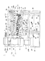
古紙再生装置1は、図9に示すような什器サイズ、つまり、事務所内に配置使用される書棚、ロッカー、事務机、複写機、パーソナルコンピュータなどの什器類と同等な小型形状寸法を備えるもので、図1に示すように、パルプ製造部2、抄紙部(抄紙装置)3および制御部4を主要部として構成され、これら装置構成部2〜4が装置ケース5内に装置収容されてなるコンパクト設計とされるとともに、上記パルプ製造部2および抄紙部3の駆動源は、一般家庭用交流電源により駆動する電動駆動源とされている。
The used
装置ケース5は、上述したように什器サイズのもので、具体的な形状寸法は目的や用途に応じて適宜設計される。図示の実施形態の装置ケース5は、事務所等に一般的に配置使用される複写機程度の形状寸法を有するほぼ直方体形状の箱体とされ、その底部には移動手段としてキャスタ6、6、…が設けられて、設置床面上を方向自在に移動可能とされている。また、装置ケース5の天板部には、古紙UPを投入するための投入口5aが設けられるとともに、側部には、再生紙RP、RP、…を受け取るための再生紙受取トレー7が取外し可能に設けられている。この再生紙受取トレー7には、装置ケース5の排出口5bが臨んで設けられており、この排出口5bから排出される再生紙RP、RP、…が順次積層状に受け取られる。
As described above, the
パルプ製造部(パルプ製造装置)2は、古紙UPを離解し叩解して古紙パルプを製造する工程部位で、古紙UPを攪拌破砕して離解する離解部10と、この離解部10で離解された古紙UPを叩解する叩解部11とからなり、図示の実施形態においては、これら離解部10および叩解部11が古紙パルプUPを所定時間循環させる循環式とされている。
The pulp manufacturing unit (pulp manufacturing apparatus) 2 is a process part that dissects and beats waste paper UP to produce waste paper pulp, and a
離解部10は、古紙UPを攪拌する攪拌装置12と、この攪拌装置12に水を供給する給水部13とを備えてなる。
The
攪拌装置12は、攪拌槽15、攪拌インペラ16および駆動モータ17を備えてなる。攪拌槽15は、図2に示すように、その天井壁に、装置ケース5の外部に対して開閉可能な構造を有する投入口5aが設けられるとともに、その内部に、上記攪拌インペラ16が回転可能に設けられている。攪拌槽15の内容積は、一度に攪拌処理すべき古紙UPの枚数に応じて設定される。図示の実施形態においては、約1.5リットルの水を加えて、A4判のPPC(plain paper copier)古紙UPを8枚程度(約32g)一度に攪拌処理(バッチ処理)できる容積を有する攪拌槽15とされている。
The stirring
また、攪拌インペラ16は、攪拌槽15の傾斜した底面部位に設けられるとともに、駆動モータ17の回転軸17a(12a)に駆動連結されて、駆動モータ17により連続的にまたは間欠的に正逆回転駆動される。駆動モータ17としては具体的には電動モータが使用され、この駆動モータ17が制御部4に電気的に接続されている。
The
このように攪拌インペラ16が正逆回転されることにより、古紙UPがA4判の大きさのままで攪拌される場合でも、攪拌インペラ16の正回転後の逆回転による水の噴流作用により、古紙UPが有効に分散させられる結果、攪拌インペラ16に絡みつくのが有効に防止されて、これにより、古紙UP、UP、…の均一な離解・叩解が実現する。
Thus, even when the used paper UP is agitated with the size of A4 size by rotating the stirring
給水部13は、図1に示すように、白水回収槽20および給水ポンプ21を備えてなる。白水回収槽20は、後述するように、抄紙部3において濾過脱水される白水W(抄紙する際に抄き網により濾過された極低濃度のパルプ水)を回収するもので、この白水回収槽20に回収された白水Wが、給水ポンプ21により、上記攪拌装置12の攪拌槽15に攪拌用の水として供給される。
As shown in FIG. 1, the
また、この給水部13は、後述するように、パルプ濃度調整部25の濃度調濃度調整用給水手段としての機能も兼備し、この目的のため、白水回収槽20内の白水Wを濃度調整槽26に濃度調整用の水として供給する濃度調整用給水ポンプ27を備えている。28および29は、白水回収槽20内に設けられた下限水位用フロートスイッチと上限水位用フロートスイッチをそれぞれ示している。
Further, as will be described later, the
そして、攪拌装置12において、装置ケース5の投入開口つまり投入口5aから攪拌槽15内に投入された古紙UP、UP、…は、駆動モータ17による攪拌インペラ16の正転・逆転動作により、給水部13から供給された水Wの中で所定時間(図示の場合は3分〜5分間)だけ攪拌され、これにより、離解・叩解されて、古紙パルプUPPとなる。
In the
叩解部11は、少なくとも一台の叩解機を備え、図示の実施形態においては一台の叩解機30を備えてなる。
The beating
叩解機30は、上記離解部10で離解された古紙UPを加圧叩解するとともに、古紙UP上の文字、図形等を形成するインキ類を磨砕微細化するものである。
The beating
叩解機30は、図3に示すように、微小な叩解隙間をもって対向配置されるとともに、相対的に移動する複数(図示の場合は二つ)の叩解部材31、32を主要部として構成され、具体的には、離解部10の攪拌槽15に連通可能な叩解槽33と、この叩解槽33内に相対的に移動可能に設けられた上記叩解部材31、32と、これら叩解部材31、32を相対的に移動させる駆動源34とを備えてなる。
As shown in FIG. 3, the beating
図示の叩解機30においては、具体的には図示しないが、上記叩解部材31、32が相対的に回転する回円盤状の形態とされ、上側の叩解部材31が固定側とされるとともに、下側の叩解部材32が回転側とされてなる。
In the illustrated beating
叩解槽33は、上記一対の叩解部材31、32を収納可能な密閉型円筒形状とされ、上側槽33aと下側槽33bが相互に螺合結合されてなる上下分割構造を備える。この叩解槽33は、上側槽33aの天部中央部に供給口35が開設されるとともに、下側槽33bの円筒側部に排出口36が開設されており、これら供給口35および排出口36は、それぞれ図示しない配管を介して、上記離解部10の攪拌槽15に連通可能に接続されている。なお、具体的には図示しないが、上記供給口35が上記攪拌槽15の底部位置に連通可能とされるとともに、上記排出口36が上記攪拌槽15の上部位置に連通可能とされている。
The
上側の固定側叩解部材31は、上記上側槽33aの天部内側面に適宜の固定手段により固定的に設けられており、この固定側叩解部材31に対して、下側の回転側叩解部材32が微小な叩解隙間Aをもって同心状にかつ回転可能に対向配置されている。
The upper fixed
この回転側叩解部材32は、回転基台38上に一体的に設けられるとともに、この回転基台38の回転支軸38aが、上記叩解槽33の底部の底部中央の開口37を介して、叩解槽33の外部へ臨み、回転駆動源である駆動モータ34の回転軸34aに直接取り付け固定されて、ダイレクトモータ構造とされている。この駆動モータ34としては具体的には電動モータが使用され、この駆動モータ34が制御部4に電気的に接続されている。
The rotation side beating member 32 is integrally provided on the
上記微小な叩解隙間Aを形成する両叩解部材31、32の対向面31a、32a同士は協働して叩解作用面を形成する。これら対向する叩解作用面31a、32aは、多数の砥粒が結合材により結合されてなる砥石面の形態とされ、また、両叩解作用面31a、32aは、図3に示すように、その径寸法が互いの対向方向へ連続的に大きくなるテーパ面形状とされて、その間に両円錐形状の叩解隙間Aが形成される。
The opposing
また、上記固定側叩解部材31の叩解作用面31aの中心部位には、叩解槽33の供給口35に同軸状に連通する入口39が形成されるとともに、両叩解部材31、32の叩解作用面31a、32aの外周縁部31b、32b間に形成される環状隙間40が叩解槽33の排出口36に連通する出口とされている。
In addition, an
また、これに関連して、回転側叩解部材32の叩解作用面32aには、複数の案内リブ41、41、…が周方向へ等間隔をもって設けられるとともに、回転側叩解部材32を支持する回転基台38の外周には、複数のブレード42、42、…が周方向へ所定間隔をもって設けられている。
In relation to this, a plurality of
回転側叩解部材32の回転により、上記複数の案内リブ41、41、…は、上記入口39から叩解隙間Aに流入する古紙パルプUPPを上記出口40へ案内する作用をなし、また、上記複数のブレード42、42、…は、この出口40から排出される古紙パルプUPPを、遠心力で上記叩解槽33の排出口36へ向けて押出すポンプ作用をなす。
By the rotation of the rotation side beating member 32, the plurality of
上記叩解隙間Aの間隙寸法は、0.05mm〜0.8mm程度に設定されている。なお、この叩解隙間Aの間隙寸法は、叩解槽33の上側槽33aと下側槽33bを相対的に回転操作して、それらの螺合部分を螺進退させることで、微調整可能とされている。このように、叩解隙間Aの間隙寸法が目的に応じて微調整可能とされることにより、上記叩解作用面31a、32aの協働作用には、装置機械構造の強度と駆動力に応じた高い圧力と摺動力が得られる。また、叩解隙間Aの間隙寸法を調整することにより、叩解部11の叩解速度(叩解時間)を適宜調整することも可能である。
The gap size of the beating gap A is set to about 0.05 mm to 0.8 mm. It should be noted that the gap size of the beating gap A can be finely adjusted by relatively rotating the
しかして、駆動モータ34により、回転側叩解部材32が固定側叩解部材31に対して回転駆動された状態において、上記離解部10の攪拌槽15から叩解槽33の供給口35へ供給される古紙パルプUPPは、上記入口39から叩解隙間Aに流入して、この叩解隙間Aを通過しながら、相対的に回転する叩解作用面31a、32aによる加圧叩解作用を受けるとともに、古紙UP上の文字、図形等を形成するインキ類が磨砕微細化され、この後、上記出口40から叩解槽33の排出口36を介して、再び上記攪拌槽15へ還流される(図3における矢符で示される流通経路を参照)。
Thus, the used paper supplied from the stirring
なお、上記叩解槽33の供給口35および排出口36は、開閉手段により開閉可能とされている。この開閉手段の具体的構造は図示しないが、例えば、従来公知の手動または自動の開閉弁が設けられてなる。これら開閉弁は、叩解部11が運転停止時には上記供給口35および排出口36を閉止して、攪拌装置12の攪拌槽15からの古紙UPや古紙パルプUPPの叩解槽33への流入を阻止する一方、叩解部11の運転時には供給口35および排出口36を開口して、攪拌槽15と叩解槽33との間での古紙パルプUPPの循環回流を許容する。
The
この場合、離解部10が叩解部11と同時に駆動していると、叩解槽33は、離解部10の攪拌槽15と共に古紙パルプUPPが回流するパルプ回流槽を構成して、このパルプ回流槽10、23を循環回流する古紙パルプUPPは、離解部10による攪拌離解作用と、叩解部11による加圧叩解作用およびインキ磨砕微細化作用を順次繰り返して受けることになる。この結果、後述する抄紙部3で抄紙再生される再生紙RPにとっての最適な紙力強度が確保されるとともに、白色度の高い再生紙RPを得ることができる(脱墨と同等な効果が得られる)。
In this case, when the
パルプ濃度調整部25は、攪拌槽15の下流側に設けられて、攪拌槽15で製造された古紙パルプUPPの濃度を後続の抄紙に適した適正濃度に調整するものである。このパルプ濃度調整部25は、攪拌槽15で製造された古紙パルプUPPを貯留する濃度調整槽26と、この濃度調整槽26に水を供給する濃度調整用給水部とを備えてなり、この濃度調整用給水部としては、前述したごとく、給水部13が兼用されている。
The pulp
濃度調整槽26の内容積は、攪拌装置12によりバッチ処理される古紙UPの枚数(量)に応じて設定される。図示の実施形態においては、前述したように、8枚程度(約32g)のA4判の古紙UPがバッチ処理されるので、これに対応した量の古紙パルプUPPの濃度を調整できる容積を有する濃度調整槽26とされている。
The internal volume of the
これに関連して、上記攪拌装置12の攪拌槽15の底部には、排水口15bが設けられており、この排水口15bは図示しない排水弁により開閉動作される構成とされている。この排水弁は具体的には電磁開閉弁からなり、上記制御部4に電気的に接続されている。
In this connection, a
パルプ濃度調整部25の具体的な濃度調整方法は、上記濃度調整槽26において、攪拌槽15内でバッチ処理にて製造された古紙パルプUPPの全量に対して、上記濃度調整用給水部13から水Wが加水されて、これら古紙パルプUPPと水Wの合計体積が所定値になることにより、所定濃度のパルプ懸濁液PSとなるように構成されている。なお、調整されるべきパルプ懸濁液PSの目標濃度は、予め行なった実験データに基づいて、後述する抄紙部3における抄紙能力を考慮して設定され、図示の場合は約0.1%濃度に設定されている。43は、濃度調整槽26内に設けられたフロートスイッチで、濃度調整槽26内のパルプ懸濁液PSの量(古紙パルプUPPと水Wの合計体積)が上記所定値になったときの水位を検知する。
The concrete concentration adjusting method of the pulp
しかして、上記濃度調整槽26において、上記攪拌槽15(および叩解槽33)で製造された古紙パルプUPPの全量が、攪拌槽15の排水口15bから自重で濃度調整槽26内へ落下供給されるとともに、この古紙パルプUPPに対して、濃度調整用給水部13から白水Wが上記所定値になるまで加水されて(フロートスイッチ43により検知)、これにより古紙パルプUPPの濃度が調整されて、所定濃度のパルプ懸濁液PSとされる。
Thus, in the
図示の実施形態においては、上記古紙パルプUPPの全量(約32gの古紙UP+1.5リットルの水W)に対して、上記濃度調整用給水部13から希釈用の水Wが加水されて、古紙パルプUPPと水Wの合計体積(全量)が32リットルになるように制御され、これにより、約0.1%濃度(目標濃度)のパルプ懸濁液PSが調製される。この濃度調整されたパルプ懸濁液PSは、第一懸濁液供給ポンプ44により、次工程の抄紙部3のパルプ供給槽90へ送られる。
In the illustrated embodiment, the water W for dilution is added from the concentration adjusting
なお、上記攪拌槽15の排水口15bから古紙パルプUPPが濃度調整槽26内へ落下供給される間、攪拌槽15内においては、給水部13から給水ポンプ21により水Wが供給されるとともに、駆動モータ17により攪拌インペラ16が回転して、攪拌槽15内の洗浄が行われる。
While the waste paper pulp UPP is dropped and supplied into the
以上のように、給水部13の給水源は、白水回収槽20に回収される抄紙部3で脱水された白水Wであり、換言すれば、抄紙部3で脱水回収される白水Wは、すべて上記離解部10の攪拌装置12およびパルプ濃度調整部25で帰還利用される水循環方式とされている。
As described above, the water supply source of the
抄紙部(抄紙装置)3は、上記離解部10で製造された古紙パルプUPPを抄紙して再生紙RPを製造する工程部位で、抄紙工程部50、脱水ロール部51および乾燥工程部52を備えてなる。
The papermaking unit (papermaking apparatus) 3 is a process part for producing recycled paper RP by making paper waste UPP produced by the
この抄紙部3は、古紙再生装置1における最重要構成部位であり、従来の古紙再生工場等の大規模工場でのみ処理可能であった再生紙製造のための抄紙を、事務所等の小さな設置空間に配置使用される複写機程度の形状寸法(什器サイズ)の装置ケース5内で実現するため、その構成装置50〜52は、以下に詳述するような種々の特徴構成を備えている。
This
抄紙工程部50は、上記パルプ製造部2の離解部10から送られてくる水Wと古紙パルプUPPが共存するスラリー状のパルプ懸濁液PSを抄いて湿紙とする部位で、抄紙コンベア55とパルプ供給部(パルプ供給装置)56を主要部として構成されている。
The paper
抄紙コンベア55は、パルプ懸濁液を抄きながら搬送するもので、上記パルプ懸濁液PSを濾過脱水する無数の網目よりなる抄き網構造の網状ベルト60がその走行方向へ向けて直線状に走行する配置構成とされている。
The
具体的には、抄紙コンベア55は、パルプ懸濁液PSを抄きながら搬送する無端ベルトの形態とされた上記網状ベルト60と、この網状ベルト60を走行駆動する駆動モータ61とを備えてなる。
Specifically, the
網状ベルト60は、具体的には、所定幅を有する抄き網構造の板材が所定長さの環状に接続形成されてなる無端ベルトである。
Specifically, the
この網状ベルト60を構成する抄き網構造の板材は、パルプ懸濁液PSが上記抄き網構造の無数の網目により適正に濾過脱水できる材質とされ、好適には、ポリプロピレン(PP)、ポリエチレンテレフタレート(PET)、ポリアミド(PA)(一般に「ナイロン」(登録商標)と呼ばれる)あるいはステンレス鋼(SUS)などの耐腐食性に優れる材料で形成されており、図示の実施形態においては、耐熱性に優れるPET製網状ベルト60とされている。
The sheet material of the mesh net structure constituting the
また、網状ベルト60を構成する抄き網構造は、網目の細かいものや織り目の細かく平滑なものが好ましく、具体的には対象となる紙の特性に対応して選択されるが、特に以下の点が考慮される。
Further, the paper making net structure constituting the
(1)網状ベルト60の網目の大きさ:
網状ベルト60の網目の大きさは、好適には25メッシュ〜80メッシュに設定され、図示の実施形態においては、50メッシュの網状ベルト60が採用されている。
(1) Mesh size of mesh belt 60:
The mesh size of the
(2)網状ベルト60の網目の線径:
網状ベルト60の網目は、メッシュ数(大きさ)だけでなく網の線径も大きく影響する。同じメッシュ数でも、線径が太いと網目の大きさが小さくなり、細いと大きくなり、これは網目の空間率、あるいは空気を通す度合いの通気度(cm3/cm2/sec)で表される。
(2) Mesh diameter of mesh belt 60:
The mesh of the
例えば、網目が細かくて通気度が悪くなると、濾水率も悪くなり、その結果、後述するパルプ供給部56の抄き枠体78が網状ベルト60の走行方向へ長くなって、装置の大型化を招く。また、逆に、網目が粗くて通気度が良すぎると、上記抄き枠体78は短くて装置も小型になるが、再生される再生紙RPは目の粗い紙質になり、表裏面の平滑度の差も大きくなって、平滑度の悪い紙となる。
For example, if the mesh is fine and the air permeability is poor, the drainage rate is also deteriorated. As a result, the
(3)織り構造:
網状ベルト60の網目の編み方としては、一重織り、二重織り、縦糸径と横糸径を変える等の方法があるが、多重織りでは後述する網状ベルト60を回転支持するロール径を大きくさせて、装置の大型化を招くことから、図示の実施形態においては、一重織りの網状ベルト60が使用されている。
(3) Weave structure:
As a method of knitting the mesh of the
以上の諸条件を考慮して、網状ベルト60としては、抄紙時に古紙パルプUPPが網状ベルト60の網目から抜け落ちるのを防ぐため、網の線径が細くて、メッシュ数が多く、かつ通気度を落とさない網目構造のものが好ましく、図示の実施形態の網状ベルト60としては、平織りで、50メッシュのPET製網状ベルト60が使用されている。この網状ベルト60によれば、筆記に問題ない良好な紙質が得られることが実験的に判明している。
Considering the above conditions, the
さらに、網状ベルト60の幅寸法は、パルプ懸濁液PSを抄いて製造すべき再生紙RPの幅寸法よりも若干大きな所定幅寸法に設定される。
Further, the width dimension of the
網状ベルト60は、図1および図4に示すように、駆動ローラ65、従動ローラ66、支持ローラ67、脱水ロール70および予備脱水ロール74を介して、回転走行可能に懸架支持されるとともに、上記駆動ローラ65を介して、上記駆動モータ61に駆動連結されている。
As shown in FIGS. 1 and 4, the
そして、上記網状ベルト60における抄紙工程長さLは、上記什器サイズの装置ケース5内における網状ベルト60の直線状走行方向長さ(図示の場合は図1および図4における左右方向長さ)の範囲内に設定されている。
The paper making process length L in the
具体的には、上記網状ベルト60の抄紙工程長さLは、その抄き網構造の濾過脱水率および網状ベルト60の走行速度との関係で、パルプ懸濁液PSが適正な坪量に抄かれるのに十分であるとともに、網状ベルト60を備える上記抄紙コンベア55が什器サイズの装置ケース5内に収容し得るように設定されている。
Specifically, the papermaking process length L of the
また、上記網状ベルト60の走行速度は、上述した諸条件を考慮して設定されるもので、好適には0.1m/分〜1m/分に設定され、図示の実施形態においては0.2m/分に設定されている。ちなみに、従来の古紙再生工場等の大規模工場でのこの種抄紙ベルトの走行速度は、少なくとも100m/分以上に設定され、早いものでは1000m/分をはるかに上回る速度に設定される。
The traveling speed of the
この網状ベルト60の走行速度は、特に抄紙工程における湿紙の坪量に影響し、網状ベルト60の走行速度が減小すると坪量は増加し、走行速度が増すと坪量が低下する。この場合、古紙パルプUPPの叩解度は網状ベルト60の濾水に影響し、叩解度およびパルプ濃度が一定条件で有れば、一定の坪量を得ることができる。
The traveling speed of the
上記網状ベルト60を走行駆動する駆動モータ61は、具体的には電動モータで、制御部4に電気的に接続されている。また、この駆動モータ61は、後述する脱水ロール部51および乾燥工程部42の走行駆動源としても共用され、この共用のための構造つまり駆動連結機構については後述する。
The drive motor 61 that travels and drives the
パルプ供給部(パルプ供給装置)56は、上記網状ベルト60上に上記パルプ製造部2の離解部10からのパルプ懸濁液PSを供給する部位で、上記抄紙コンベア55の抄紙工程開始端位置に設けられており、このパルプ供給部56により、パルプ懸濁液PSが上記網状ベルト60上面に均一に広がり供給される構成とされている。
The pulp supply unit (pulp supply device) 56 is a part for supplying the pulp suspension PS from the
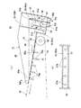
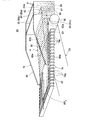
図示のパルプ供給部56の具体的構造が図6および図7に示されている。すなわち、このパルプ供給部56において、上記網状ベルト60が上述のごとく走行方向へ向けて上向き傾斜状に配置されるとともに、この網状ベルト60の上下両側位置に、抄き枠体78および仕切り部材79がそれぞれ配置されてなる。
The specific structure of the illustrated
抄き枠体78は、網状ベルト60の上面に摺接可能に配設されるとともに、上記パルプ製造部2から送られてくるパルプ懸濁液PSの供給幅を規定するもので、図6および図7に示すように、本体枠80、この本体枠80の内側に設けられた流通路81、この流通路81の出口側部位に設けられた平板部材82、および本体枠80の後端部に設けられたオーバフロー堰83とを備える。
The
本体枠80は、先端部つまり網状ベルト60の走行方向側端部が開放された平面コ字形状とされ、その下端面80aが傾斜走行する上記網状ベルト60の上面に摺接するように配されるとともに、本体枠80の枠内幅寸法L(図8参照)が製造すべき再生紙RPの幅寸法に設定されている。
The
流通路81は、供給された上記パルプ懸濁液PSの均等な分散を促すもので、曲がりくねった流通路の形態とされ、上記抄き枠体78内における上記オーバーフロー堰83の下流側に設けられている。
The
上記流通路81は、具体的には、本体枠80内に設けられた複数の堰部材85、85、…から主として構成され、図示の実施形態においては、本体枠80の底面を形成する底板86と、本体枠80内に起立状に設けられた3枚の堰部材85a、85b、85cと、上記オーバーフロー堰83とから、上記流通路81が形成されている。
Specifically, the
具体的には、図7(a)に示すように、上記3枚の堰部材85a、85b、85cおよび上記オーバーフロー堰83が上記本体枠80内に所定の等間隔をもって起立状にかつ平行に設けられて、上記流通路81が上下方向へ曲がりくねって形成されており、この流通路81の進行方向は、その入口81aつまり上記底板86に開設された開口から上方向へ向けて延びる一方、その出口81bへ向けて上方向へ延びる構成とされている(図7(a)における矢符参照)。上記入口81aは、パルプ懸濁液PSを供給するパルプ供給槽90に連通可能とされている。
Specifically, as shown in FIG. 7A, the three
なお、これら流通路81を形成する各部材83、85a、85b、85c、86と本体枠80との組立構造は、図示実施形態のように、別個独立して形成した各部材を一体的に接続組立てされるほか、射出成形可能なプラスチック製など、一体成形可能な材料から形成される場合には一体成形されても良い。
The assembly structure of the
これら本体枠80内に起立状に設けられた堰部材85a、85b、85cのうち、上記流通路81の上向きから下向きに変わる部位を仕切り形成する堰部材、つまり本実施形態においては堰部材85aの上端縁は、後述するように、平板部材82上に流れて滞留するパルプ懸濁液PSの水位、つまり、オーバーフロー堰83により規定される水位Hよりも下位に位置するように設定されている。
Among the
また、上記流通路81の入口81aの近傍位置には、仕切り板87が流通路81を仕切るように設けられるとともに、この仕切り板87に、図7(b)に示すように、複数の連通孔87a、87a、…が所定間隔をもって開設されている。
Further, a
平板部材82は、流通路81の出口81b側部位に設けられて、上記網状ベルト60の網目を上側から閉塞状態に被覆している。この平板部材82は、上記網状ベルト60の走行方向へ向けて平行する上向き傾斜状の上り勾配に設定配置されている。
The
これに関連して、仕切り部材79は、複数本の骨組み部材79a、79a、…からなる水切り可能なスノコ構造を備え、上記網状ベルト60の下面全幅を摺接支持する形状寸法を有する。
In relation to this, the
また、上記平板部材82の先端縁には、上記網状ベルト60上へのパルプ懸濁液の円滑な流れを確保するための薄い案内シート88が設けられている。この案内シート88の先端縁88aは、上記仕切り部材79のスノコ構造を形成する桟つまり上記骨組み部材79a、79a、…の一つ(本実施形態においては最後部の桟79a)に対応した位置に設定され、具体的には、この桟79aにより支持される網状ベルト60の上面部位に摺接配置されている。
A
オーバーフロー堰83は、上述したように、上記抄き枠体78内に滞留される上記パルプ懸濁液PSの水位Hを一定にするためのもので、その上端縁83aが水平直線状に形成されるとともに、その高さ位置は、網状ベルト60上に抄かれる湿紙RP0さらには再生紙RPの坪量を所望の値に安定して維持すべく、網状ベルト60の前述した諸条件に対応して設定される。
As described above, the
すなわち、上記網状ベルト60上に抄かれる湿紙RP0の坪量を安定して確保するためには、上記抄き枠体78におけるパルプ懸濁液PSの滞留作用が重要な要素であり、この滞留作用は、抄き枠体78内におけるパルプ懸濁液PSの水量(滞留水量)に大きく影響される。このため、このパルプ懸濁液PSの水量を一定させることがきわめて重要である。
That is, in order to stably secure the basis weight of the wet paper RP 0 to ska on the
本パルプ供給部(パルプ供給装置)56においては、上記オーバーフロー堰83が設けられることで、上記抄き枠体78内のパルプ懸濁液PSの水量が所定値に安定して維持される構成とされている。
In the present pulp supply unit (pulp supply device) 56, by providing the
また、オーバフロー堰83が上記流通路81の出口側部位でなく、流通路81の入口側部位つまり上流側に設けられていることにより、パルプ懸濁液PSの水位Hの脈打ち現象が有効に防止され得る。
Further, since the
オーバフロー堰83が上記流通路81の出口側部位に設けられると、パルプ懸濁液PSが網状ベルト60の抄き網構造で濾水されて、上記水位Hが低下すると、流通路81の出口81bから出たパルプ懸濁液PSが、上記オーバフロー堰83を乗り越える間のタイムラグを生じ、これにより水位Hが脈打ちを起こして、再生紙RPの地合に横縞模様を生じさせてしまう。
When the
これに対して、図示の実施形態のように、オーバフロー堰83が流通路81の上流側部位に設けられていることで、このような不具合が有効に回避される。
On the other hand, such an inconvenience is effectively avoided by providing the
上記オーバーフロー堰83の後側には、このオーバーフロー堰83と本体枠80の後部壁部分とにより形成されたパルプ懸濁液回収部89が設けられている。オーバーフロー堰83からオーバーフローしたパルプ懸濁液PSは、このパルプ懸濁液回収部89に流下回収されるとともに、底板86に開設された排出口89aから前記白水回収槽20へ回収される。
A pulp
また、上記パルプ供給部56の上流側には、このパルプ供給部56にパルプ懸濁液PSを供給されるパルプ供給槽90が設けられている。
Further, on the upstream side of the
このパルプ供給槽90には、パルプ製造部2で製造されたパルプ懸濁液PSが第一懸濁液供給ポンプ44により供給されて貯留される。このパルプ供給槽90内には、貯留されるパルプ懸濁液PSを攪拌するための攪拌装置91が設けられおり、パルプ懸濁液PSの濃度が均一に保たれる。
In the
このパルプ供給槽90に貯留されるパルプ懸濁液PSは、下限水位用フロートスイッチ92および上限水位用フロートスイッチ93により検知されて、第二懸濁液供給ポンプ94により、上記パルプ供給部56の抄き枠体78内へ連続的に供給される構成とされている。
The pulp suspension PS stored in the
しかして、上記パルプ供給槽90に貯留されるパルプ懸濁液PSが、第二懸濁液供給ポンプ94により、上記入口81aから抄き枠体78内の流通路81に供給されると、この曲がりくねった流通路81を図7に矢符にて示されるようにゆっくりと通過した後に、出口81bから平板部材82上に流れて、上記オーバーフロー堰83により規定される一定水位Hまで滞留し、これにより、走行方向へ向けて上向き傾斜状に配置されて走行する上記網状ベルト60上面に均一に拡散して供給される。
When the pulp suspension PS stored in the
一方、上記オーバーフロー堰83からオーバフローしてパルプ懸濁液回収部89に回収されたパルプ懸濁液PSは、上記のごとく白水回収槽20へ回収される。
On the other hand, the pulp suspension PS overflowed from the
上記パルプ供給部56におけるパルプ懸濁液PSの流通経路構造における作用効果は以下のとおりと推測される。
The effects of the pulp suspension PS in the flow path structure in the
(i)複数の連通孔87a、87a、…を有する仕切り板87の存在:
仕切り板87が流通路81を仕切るように設けられるとともに、この仕切り板87に、複数の連通孔87a、87a、…が開設されていることにより、パルプ供給槽90から供給されるパルプ懸濁液PSが、この仕切り版87の複数の連通孔87a、87a、…を通過する際に、流通路81全体に分散されて、流通路81の断面開口全体に流量が均一になるように調整される。
(I) Presence of the
A
(ii)流通路81の曲がりくねった経路:
堰部材85(85a、85b、85c)により区画形成される曲流通路81は曲がりくねって長く、パルプ懸濁液PSがこのような流通路81を通過することで、均等に分散される。
(Ii) The winding path of the flow path 81:
The
(iii)オーバーフロー堰83:
オーバーフロー堰83の存在により、抄き枠体78内に送られるパルプ懸濁液PSの供給水量に変動が生じても、抄き枠体78内に滞留するパルプ懸濁液PSの水位Hは常時一定に維持されて、その結果、網状ベルト60上に抄かれる湿紙RP0の坪量を安定させることができる。
(Iii) Overflow weir 83:
Even if the supply water amount of the pulp suspension PS fed into the
(iv)平板部材82の先端縁の薄い案内シート88:
案内シート88の先端縁88aが、仕切り部材79のスノコ構造を形成する桟79aにより支持される網状ベルト60の上面部位に摺接配置されていることにより、網状ベルト60のネットによる均一な濾水が確保される。
(Iv)
Since the
仕切り部材79の桟79a、79a間にあると、パルプ懸濁液PSは網状ベルト60の抄き網構造から濾水される際に、従動ローラ66の方向にも自由に流れる傾向にあり、これがため、網目による均一な濾水が困難で、局所的に不均一な濾水箇所が現れてしまう。このように濾水が不均一な場合、再生紙RPの地合に縦縞模様を生じさせてしまう。
If it is between the
これに対して、図示の実施形態のように、案内シート88の先端縁88aが、仕切り部材79のスノコ構造を形成する桟79aの上面位置に設定されていることで、このような不具合が有効に回避される。
In contrast, as shown in the illustrated embodiment, the
脱水ロール部51は、上述の抄紙工程部50と後述の乾燥工程部42の連係部において、上記網状ベルト60上の湿紙RP0を圧搾脱水する部位である。
The
具体的には、下流側の上記乾燥工程部42の後述する平滑面ベルト95と上流側の上記抄紙工程部50の網状ベルト60とが図1および図4に示すように、上下に積層状に配設されるとともに、これら平滑面ベルト95と網状ベルト60の上下隣接部分が上記連係部とされて、上記脱水ロール部51が、これら網状ベルト60および平滑面ベルト95を上下両側から挟圧状に転動圧搾する構造とされている。
Specifically, as shown in FIGS. 1 and 4, a smooth surface belt 95 (to be described later) of the
上記脱水ロール部51は、脱水ロール70、プレスロール71および駆動モータ72を主要部として備えるととともに、その補助部として、予備脱水ロール74およびスラリー化防止ロール75が設けられている。
The
脱水ロール70は、網状ベルト60に下側から転接するもので、具体的には、高剛性材料からなる円筒ロール70aの外周に、微細連続気孔の多孔質材料からなる脱水層70bが巻装されてなる。脱水層70bは、親水性、吸水性および保水性に優れる材料からなり、好適には柔軟性に優れる微細連続気孔の多孔質材料からなる。また、脱水層70bの円筒ロール70aに対する巻装構造としては、ある程度厚みのある脱水層70bを円筒ロール70aの外周に一回巻きしたり、あるいは円筒状の脱水層70bを円筒ロール70aに外嵌する単層構造と、薄い脱水層70bを円筒ロール70aの外周に複数回巻きする多層構造とがある。
The
図示の実施形態の脱水ロール70は、ステンレス鋼製円筒ロール70aの円筒外周面に、ミクロンサイズの超微細な連続気孔を有する超微細連続発泡材料からなる円筒状の脱水層70bが外嵌されてなる単層構造とされている。
The
プレスロール71は、後述する乾燥工程部42の平滑面ベルト95を上側から転動加圧するもので、具体的には、高剛性材料からなる円筒ロールの形態とされている。図示の実施形態のプレスロール71は、ステンレス鋼製円筒ロールからなる。
The
これら脱水ロール70とプレスロール71は、具体的には単一の駆動モータ72に駆動連結されて、両ロール70、71が連動して回転駆動される。この場合、これら両ロール70、71は、その外周面間において挟圧状に転動圧搾される網状ベルト60、平滑面ベルト95の接触面(網状ベルト60の下面および平滑面ベルト95の上面)に対して、両ロール70、71の外周面が、互いに僅かの回転速度差をもってそれぞれ転動接触するように回転制御される。
Specifically, the
具体的には、プレスロール71の回転速度が脱水ロール70の回転速度よりも僅かに大きく設定されており、これにより、平滑面ベルト95の走行速度が、上記網状ベルト60の走行速度よりも大きく設定されることになる。このような構成とされることにより、後述するように、脱水ロール部51により圧搾脱水された湿紙RP0が、下側の網状ベルト60の上面から上側の平滑面ベルト95の下面に転写移転される際に、湿紙RP0にテンションがかかって、湿紙RP0に皺が発生するのを有効に防止する。
Specifically, the rotational speed of the
また、上記駆動モータ72は、図示の実施形態においては、後述するように、抄紙工程部50の駆動モータ61が共用とされている。
In the illustrated embodiment, the drive motor 72 is shared with the drive motor 61 of the paper
そして、この駆動モータ72の駆動により、上記両ロール70、71が、上記両ベルト60、95を上下両側から挟圧状に転動圧搾して、網状ベルト60上の湿紙RP0に含まれている水分Mが上記網状ベルト60を介して上記脱水ロール70に吸水されて脱水される。この圧搾脱水された白水Wは、給水部13の白水回収槽20に回収される。
Then, by driving the drive motor 72, both the
この圧搾脱水の具体的メカニズムを図8(a)により説明すると、上記両ロール70、71の回転により、上面に湿紙RP0を載置した網状ベルト60と平滑面ベルト95が、その間に上記湿紙RP0を介在させた状態で、上記両ロール70、71間へ案内されて、上下両側から挟圧状に転動圧搾される。すると、湿紙RP0に含まれている水分Mは、上記両ロール70、71の上流側(図面において右側)へ搾り出されるが、上側の平滑面ベルト95が後述するように平滑面を有する孔のない構造であることから、この搾り出された水分Mはすべて下側の網状ベルト60の微細な連続気孔を通過して上記脱水ロール70の脱水層70bに吸水される。
The specific mechanism of the pressure dehydration will be described with reference to FIG. 8A. By rotating both the
予備脱水ロール74およびスラリー化防止ロール75は、これら脱水ロール部51におけるプレスロール71と脱水ロール70による圧搾脱水作用を補助するために設けられている。
The
予備脱水ロール74は、図1に示すように、脱水ロール部51の上流側において、上記網状ベルト60に下側から転接してテンションを与えるように配設されている。
As shown in FIG. 1, the
この予備脱水ロール74の具体的構造は、上記脱水ロール70と同様であり、高剛性材料からなる円筒ロール74aの外周に、微細連続気孔の多孔質材料からなる脱水層74bが巻装されてなる。図示の実施形態の予備脱水ロール74は、ステンレス鋼製円筒ロール74aの円筒外周面に、ミクロンサイズの超微細な連続気孔を有する超微細連続発泡材料からなる円筒状の脱水層74bが外嵌されてなる単層構造とされている。
The specific structure of the
そして、網状ベルト60上面に均一に拡散されて、この網状ベルト60と共に搬送される湿紙RP0は、網状ベルト60により濾過脱水されながら、上記予備脱水ロール74によっても複合的に吸水脱水されて、プレスロール71と脱水ロール70による圧搾脱水作用を予備的に補助する。
Then, the wet paper RP0 that is uniformly diffused on the upper surface of the
スラリー化防止ロール75は、図1および図8(b)に示すように、脱水ロール部51の上流側近傍位置において、上記平滑面ベルト95を上側から転動加圧して、平滑面ベルト95を下側の網状ベルト60上の湿紙RP0に押さえ付けるように配設されている。
As shown in FIGS. 1 and 8 (b), the
そして、図8(b)を参照して、脱水ロール70とプレスロール71により、上面に湿紙RP0を載置した網状ベルト60と平滑面ベルト95が上下両側から挟圧状に転動圧搾されると、湿紙RP0に含まれている水分Mは、両ロール70、71の上流側(図面において右側)へ搾り出されるが、同時に、脱水ロール70自身が先の圧搾脱水の結果保水している水分Mもまた搾り出される。
8B, the
この場合、スラリー化防止ロール75が設けられていないとすると、図8(a)に示すように、両ロール70、71の上流側近傍位置においては、上側の平滑面ベルト95と下側の網状ベルト60との交差角度(これら両ベルト60、95が両ロール70、71による挟圧点を交点として挟む角度)が比較的大きく、これにより、上側の平滑面ベルト95が下側の網状ベルト60上の湿紙RP0に対して離隔した状態にある。このため、両ロール70、71の上流側へ搾り出された上記湿紙RP0に含まれている水分と脱水ロール70自身が保水していた水分の複合された水分Mの一部M´が、上記網状ベルト60を介して上記脱水ロール70に吸水されずに、湿紙RP0に吸収されて、湿紙RP0が再びスラリー化してしまうおそれがある。
In this case, if the
なお、上側の平滑面ベルト95と下側の網状ベルト60との交差角度がそれほど大きくない場合には、上記のような問題は起こらないため、上記スラリー化防止ロール75の設置を省略することも可能である。
In addition, when the crossing angle between the upper
上記脱水ロール部51により圧搾脱水された湿紙RP0は、脱水ロール部51の下流側部位において、下側の網状ベルト60の上面から上側の平滑面ベルト95の下面に転写移転されて、平滑面ベルト95と共に搬送されて、乾燥工程部42による乾燥工程が実施される。
The wet paper RP0 squeezed and dewatered by the
なお、上記移転作用は平滑面ベルト95の平滑面構造により起こるものと考えられる。つまり、下側の網状ベルト60の表面が、微細な連続気孔が多数開口されてなる微細凹凸面であるのに対して、上側の平滑面ベルト95の表面が孔のない平滑面であり、この結果、僅かに水分を含んでいる湿紙RP0が上記平滑面ベルト95の表面との間の表面張力で吸着されるものと考えられる。
Note that the transfer action is considered to occur due to the smooth surface structure of the
また、前述したように、平滑面ベルト95の走行速度は、網状ベルト60の走行速度よりも大きく設定されており、これにより、脱水ロール部51により圧搾脱水された湿紙RP0が、下側の網状ベルト60の上面から上側の平滑面ベルト95の下面に転写移転されるに際して、上記湿紙RP0に上記速度差によるテンションがかけられる結果、湿紙RP0は皺が寄ることなく平滑な状態で平滑面ベルト95に転写され得る。
Further, as described above, the traveling speed of the
乾燥工程部42は、上記抄紙工程部50で抄紙形成された後、脱水ロール部51で圧搾脱水された湿紙RP0を乾燥させて再生紙RPとする部位で、乾燥コンベア91と加熱乾燥部92を主要部として構成されている。
The
乾燥コンベア91は、脱水ロール部51で圧搾脱水された湿紙RP0を平滑にしながら搬送するもので、上記平滑面ベルト95とこの平滑面ベルト95を走行駆動する駆動モータ96とを備えてなる。
The drying
平滑面ベルト95は、湿紙RP0を加熱乾燥させながら搬送するもので、具体的には、所定幅を有する平滑面構造の板材が所定長さの環状に接続形成されてなる無端ベルトである。
The
上記所定幅は、網状ベルト60と同様に、製造すべき再生紙RPの幅寸法よりも若干大きな寸法に設定される。また、平滑面構造の板材は、湿紙RP0の片側表面を適正な平滑面に仕上げることができ、かつ後述する加熱乾燥部97による加熱作用に耐え得る材質とされ、好適には、フッ素樹脂、ステンレス鋼等の可撓性耐熱材料で形成されており、図示の実施形態においては、フッ素樹脂製ベルトが採用されている。さらに、上記所定長さは、湿紙RP0が完成品である再生紙RPに加熱乾燥されるのに十分な長さで、かつ装置ケース5における乾燥ベルトコンベア部42の収容空間に収容し得る大きさに設定される。
The predetermined width is set to a size slightly larger than the width of the recycled paper RP to be manufactured, like the
この平滑面ベルト95は、図1および図4に示すように、駆動ローラ100、従動ローラ101、102、プレスロール71、スラリー化防止ロール75、平滑面仕上げロール103、103および予備脱水ロール74を介して、回転走行可能に懸架支持されるとともに、上記駆動ローラ100を介して、上記駆動モータ96に駆動連結されている。
As shown in FIGS. 1 and 4, the
平滑面ベルト95を走行駆動する駆動モータ96は、前述したように、上記抄紙工程部50および脱水ロール部41の走行駆動源としても共用され、この共用のための構造つまり駆動連結機構が図6に示されている。
As described above, the drive motor 96 that travels the
図4において、105は動力伝達ギヤ、106はスプロケット、107はスプロケット106、106間に掛け渡される動力伝達チェーン、および78は動力伝達軸をそれぞれ示している。
4, 105 is a power transmission gear, 106 is a sprocket, 107 is a power transmission chain spanned between the
上記動力伝達ギヤ105、105、…、スプロケット106、106、…の歯車比は、駆動源が単一の駆動モータ96であることから、駆動ローラ100、従動ローラ101、102、プレスロール71、スラリー化防止ロール75、平滑面仕上げロール103、103および予備脱水ロール74のすべてが、平滑面ベルト95に対して、互いに実質的に同一の周速度をもってそれぞれ転動接触するように設定されている。
The gear ratio of the power transmission gears 105, 105,...,
加熱乾燥部92は、上記平滑面ベルト95上の湿紙RP0を加熱乾燥する部位で、上記平滑面ベルト95の走行経路途中箇所に配されたヒータプレート109を加熱部として備える。
The heating and drying
図示の実施形態のヒータプレート109は、上記平滑面ベルト95の走行経路における水平走行部分に設けられており、具体的には、平滑面ベルト95における上記湿紙RP0の保持面である上面と反対側面つまり下面に摺接して設けられている。これにより、上記平滑面ベルト95上の湿紙RP0は、上記ヒータプレート109により加熱された平滑面ベルト95により間接的に加熱乾燥されることとなる。
The
また、平滑面ベルト95の走行途中に、上記2つの平滑面仕上げロール103、103が配設されている。具体的には、これら平滑面仕上げロール103、103は、上記平滑面ベルト95の走行経路における水平走行部分において、上記ヒータプレート109と対向して並列状に配置されている。
In addition, the two smooth surface finishing rolls 103 and 103 are disposed while the
そして、両平滑面仕上げロール103、103は、平滑面ベルト95上の湿紙RP0を順次転動加圧して、平滑面ベルト95の表面に接触する湿紙RP0の片側表面と反対側表面を適正な平滑面に仕上げる。
Then, both smooth surface finishing rolls 103 and 103 roll and press the wet paper RP0 on the
なお、図示の実施形態においては、2つの平滑面仕上げロール103、103が設けられているが、平滑面仕上げロールの配設数は目的に応じて適宜増減される。 In the illustrated embodiment, two smooth surface finishing rolls 103 and 103 are provided, but the number of smooth surface finishing rolls is appropriately increased or decreased according to the purpose.
上記平滑面ベルト95における上記加熱乾燥部92の下流側には、剥離部材110が設けられている。この剥離部材110は、具体的には耐熱性を有する弾性ヘラの形態とされており、図示の実施形態の剥離部材110は、弾性変形可能な0.1〜0.3mm厚程度のステンレス鋼板の外周面にテフロン(登録商標)加工が施されてなり、その基端部が固定側に支持されるとともに(図示省略)、その先端エッジ110aが上記平滑面ベルト95の表面に弾発的に当接係止されている。
A peeling
そして、平滑面ベルト95上で乾燥処理されて搬送される乾紙つまり再生紙RPは、上記剥離部材110の先端エッジ110aにより、平滑面ベルト95の保持面から順次剥離されることとなる。
Then, the dry paper, that is, recycled paper RP, which is transported after being dried on the
これに関連して、この剥離部材110の下流側つまり平滑面ベルト95の走行経路終端位置、つまり乾燥工程部42の終端位置には、上記平滑面ベルト95から剥離された再生紙RPを所定形状寸法(図示の場合は長さ寸法のみ)に切断する定寸カッタ111が設けられている。この定寸カッタ111の具体的構造は図示しないが、例えば、従来公知の両サイドスリッターの形態とされ、ソレノイドによりギロチンカット動作する構造が採用され得る。
In relation to this, the recycled paper RP peeled off from the
そして、平滑面ベルト95から剥離された再生紙RPは、定寸カッタ111により所定長さ(図示の実施形態においては、A4版の縦寸法)に切断されて、再使用可能な形状寸法の再生紙RPとされ、装置ケース5の排出口5bから排出される。なお、この場合の所定長さでの切断は、平滑面ベルト95のベルト送り量を近接スイッチ、エンコーダ等のセンサにより計測して行う。
Then, the recycled paper RP peeled off from the
制御部4は、上述した離解部10および抄紙部3の各駆動部の動作を相互に連動して自動制御するもので、具体的には、CPU,ROM,RAMおよびI/Oポートなどからなるマイクロコンピュータで構成されている。
The control unit 4 automatically controls the operations of the drive units of the
この制御部4には、パルプ製造部2のパルプ製造工程および抄紙部3の抄紙工程を連続して実行させるためのプログラム等が組み込まれるとともに、各駆動部の駆動に必要な種々の情報、例えば、離解部10における攪拌装置12の駆動時間および給水部13の動作タイミング、あるいは、抄紙部3におけるコンベア部40、42の走行速度、加熱乾燥部92の駆動時間および定寸カッタ111の動作タイミングなどが、予めデータとしてまたはキーボード等により適宜選択的に入力設定されている。
The control unit 4 incorporates a program for continuously executing the pulp manufacturing process of the pulp manufacturing unit 2 and the paper making process of the
また、上記制御部4には、前述したように、各フロートスイッチ28、29、43、87、88および各駆動部17、874、61(72、96)、89、105、111が電気的に接続されており、制御部4は、これらの各種実測値およびデータに従って、上記各駆動部17、874、61(72、96)、89、105、111を制御する。
Further, as described above, the
しかして、以上のように構成された古紙再生装置1は、電源投入により起動して、制御部4により各駆動部が相互に関連して自動制御され、これにより、装置ケース5の投入口5aに投入された古紙UP、UP、…は、パルプ製造部2、離解部10および叩解部11により離解・叩解処理されて、古紙パルプUPPが製造された後、さらにこの古紙パルプUPPが抄紙部3の抄紙工程部50、脱水ロール部51および乾燥工程部52により抄紙されて、再生紙RPとして再生され、装置ケース5の排出口5bから再生紙受取トレー7に排出される。
Thus, the used
以上のように構成された古紙再生装置1において、抄紙部3のパルプ供給部(パルプ供給装置)56は、抄紙工程部50の走行する無端網状ベルト60の下面に摺接可能に配設された仕切り部材79と、上記網状ベルト60の上面に摺接可能に配設されるとともに、パルプ製造部2から送られてくるパルプ懸濁液PSの供給幅を規定する抄き枠体78とを備え、この抄き枠体78内に、滞留される上記パルプ懸濁液PSの水位を一定にするオーバフロー堰83が設けられ、上記抄き枠体78内に供給されたパルプ懸濁液PSが、上記オーバフロー堰83により規定される一定水位Hまで滞留し、走行方向へ向けて上向き傾斜状に配置されて走行する上記網状ベルト60上面に均一に拡散して供給されるから、抄き枠体78内に送られるパルプ懸濁液PSの供給水量に変動が生じても、抄き枠体78内に滞留するパルプ懸濁液の水位Hは常時一定に維持されて、その結果、上記網状ベルト60上に抄かれる湿紙RP0の坪量が安定し、ひいては均一な地合の再生紙RPを得ることができる。
In the used
さらに、上記パルプ供給部56を備える抄紙装置3にあっては、以下に列挙するような優れた特有の効果が得られ、大きな事業所等だけでなく、小規模店舗や一般家庭などにも設置可能であるとともに、環境に優しくかつランニングコストも低く抑えることができ、しかも、機密情報や個人情報など各種情報の漏洩・流出を確実に防止できて、高い機密性を保持することができる古紙再生装置1を提供することができる。
Furthermore, in the
(1)什器サイズの装置ケース5内に、古紙UPを離解し叩解して古紙パルプUPPを製造するパルプ製造部2と、このパルプ製造部2で製造された古紙パルプUPPを抄紙して再生紙RPを製造する抄紙部(抄紙装置)3とを備えてなる小型簡素な構造の古紙再生装置1が実現し、これにより、古紙UPを廃棄処分することなく、古紙UPの発生元において自前で再生利用することができ、古紙UPの廃棄を軽減して、ゴミ問題解決に役立つばかりか、限りある資源を有効利用することができる。
(1) A pulp manufacturing unit 2 that separates and beats used paper UP to produce used paper pulp UPP in a furniture-
特に、この種の古紙UPは機密上の問題からリサイクル化が進んでおらず、上記のように古紙UPの発生元において自前で再生利用することができることにより、資源有効利用の効果は顕著である。 In particular, this type of used paper UP has not been recycled due to security problems, and can be recycled and reused at the source of the used paper UP as described above, so that the effect of effective resource utilization is remarkable. .
(2)また、古紙UPの発生場所に、製紙工場や古紙再生工場の大規模な設備と同様な機能を有するコンパクトな古紙再生設備が設置されることにより、小規模店舗や一般家庭などにおいても、連続して紙の循環使用を可能にすることができ、さらには、古紙UPの回収廃棄に要する輸送費や焼却費等の各種経費も不要となって、経済的である。 (2) In addition, by installing compact used paper recycling equipment that has the same functions as large-scale equipment in paper mills and used paper recycling factories at the location where used paper UP occurs, it can be used in small stores and general households. Further, it is possible to continuously circulate the paper, and it is economical because various expenses such as transportation costs and incineration costs required for collecting and discarding the used paper UP are unnecessary.
(3)装置構造がコンパクトで、大きな事業所等だけでなく、小規模店舗や一般家庭などにも設置可能であり、この観点からも、機密情報や個人情報など各種情報の漏洩・流出を確実に防止することができる。 (3) The device structure is compact and can be installed not only in large offices, but also in small stores and general households. From this point of view, the leakage and outflow of various information such as confidential information and personal information is ensured. Can be prevented.
(4)古紙UPが発生する場所に配置されて、パルプ製造部2により、発生した古紙UPが離解処理されて古紙パルプUPPとされるとともに、抄紙部3により、上記古紙パルプUPPが抄紙されて再生紙RPとされ、これにより、上記古紙UPが、その発生場所内において再生紙RPとして循環使用される構成とされていることにより、古紙UPに記載された文字や線図等の各種情報が古紙UPの発生場所外へ拡散することが全くなく、この点からも、機密情報や個人情報の漏洩・流出を確実に防止することができ、高い機密性を保持することができ、また資源の有効利用を図ることもできる。
(4) The used paper UP is disposed at a place where the used paper UP is generated, the generated paper UP is disaggregated by the pulp manufacturing unit 2 to be used as the used paper pulp UPP, and the used paper pulp UPP is processed by the
すなわち、本実施形態の抄紙装置3を抄紙部として備える古紙再生装置1を使用することにより、その使用に係る一定の系(例えば、学校、病院、市役所、法律事務所、特許事務所、一般家庭等)の外へ上記各種情報が拡散するおそれが全くなくなる。
That is, by using the used
換言すれば、例えば従来周知のシュレッダの場合、古紙が裁断されて小片となり、そこに記載された文字や線図が判読不能となったとしても、裁断された紙片は焼却場等で廃棄処分されることになるため、上記系外への拡散を完全に防止することはできない。この点に関して、上記系外への拡散を防止する目的で、系内の倉庫に保管するという方法も考えられるが、反面、そのような保管場所の確保が必要となり、対象となる紙も一回の使用のみでは、資源の有効利用という観点から効率が悪い。 In other words, for example, in the case of a conventionally known shredder, even if the waste paper is cut into small pieces and the characters and diagrams described there become unreadable, the cut paper pieces are discarded at an incinerator or the like. Therefore, the diffusion outside the system cannot be completely prevented. In this regard, it is conceivable to store in a warehouse in the system for the purpose of preventing the diffusion outside the system, but on the other hand, it is necessary to secure such a storage place, and the target paper is also used once. The use of only is inefficient from the viewpoint of effective use of resources.
これに対して、本実施形態の古紙再生装置1によれば、古紙UPに記載される各種情報がその使用に係る系外へと拡散しまうことは全くなく、しかも、資源を有効に活用することができる。
On the other hand, according to the used
実施形態2
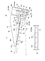
本実施形態は図10および図11に示されており、具体的には、抄き枠体78内の構造が若干改変されたものである。
Embodiment 2
This embodiment is shown in FIG. 10 and FIG. 11, and specifically, the structure in the
すなわち、本実施形態においては、流通路81の出口81b側部位に設けられる平板部材82が、上向き傾斜状の上り勾配に設定配置された実施形態1の場合と逆に、網状ベルト60の走行方向へ向けて下向き傾斜状の下り勾配に設定配置されている。
That is, in the present embodiment, the traveling direction of the
具体的には、上記平板部材82は、堰部材85cと共に、図示のような三角形状断面輪郭を有する中空の板枠の形態とされて、下側板部材82aが網状ベルト60の網目を上側から閉塞状態に被覆するとともに、上側板部材82bが網状ベルト60の走行方向へ向けて下向き傾斜状の下り勾配に設定配置されている。
Specifically, the
しかして、曲がりくねった流通路81を図7に矢符にて示されるようにゆっくりと通過したパルプ懸濁液PSは、流通路81の出口81bから平板部材82の上側板部材82b上に流下して、上記オーバーフロー堰83により規定される一定水位Hまで滞留し、これにより、走行方向へ向けて上向き傾斜状に配置されて走行する上記網状ベルト60上面に均一に拡散して供給される。
Thus, the pulp suspension PS slowly passing through the winding
この場合、平板部材82が下向き傾斜状の下り勾配とされていることによって、平板部材82上に滞留するパルプ懸濁液PSの乱流の発生が有効に防止されて、再生紙RPの地合をより向上させることが可能となる。
In this case, since the
すなわち、平板部材82が上り勾配とされている場合、流通路81の出口81bから平板部材82上に流れるパルプ懸濁液PSは、この平板部材82上を上っていくことになり、パルプ懸濁液PSに乱流が起きることがあり、もし平板部材82上に滞留するパルプ懸濁液PSに乱流が起こると、網状ベルト60により抄紙される再生紙RPの地合にも影響を与えることが考えられる。
That is, when the
本実施形態では、この点を考慮して、下り勾配の平板部材82が採用されており、これにより、流通路81の出口81bから平板部材82上に流れるパルプ懸濁液PSが、平板部材82上面を円滑に流下して、乱流の発生が有効に防止され、再生紙RPの地合がより向上されることが可能となる。
その他の構成および作用は実施形態1と同様である。
In the present embodiment, in consideration of this point, the downwardly inclined
Other configurations and operations are the same as those of the first embodiment.
なお、上述した実施形態はあくまでも本発明の好適な実施態様を示すものであって、本発明はこれに限定されることなく、その範囲内で種々の設計変更が可能である。一例として以下のような改変が可能である。 Note that the above-described embodiment is merely a preferred embodiment of the present invention, and the present invention is not limited to this, and various design changes can be made within the scope thereof. For example, the following modifications are possible.
UP 古紙
CUP 裁断古紙
W 水(白水)
UPP 古紙パルプ
PS パルプ懸濁液
RP0 湿紙
RP 再生紙
1 古紙再生装置
2 パルプ製造部(パルプ製造装置)
3 抄紙部(抄紙装置)
4 制御部
5 装置ケース
10 離解部
11 叩解部
50 抄紙工程部
51 脱水ロール部
52 乾燥工程部
55 抄紙コンベア
56 パルプ供給部(パルプ供給装置)
60 網状ベルト
61 駆動モータ
70 脱水ロール
71 プレスロール
72 駆動モータ
74 予備脱水ロール
75 スラリー化防止ロール
78 抄き枠体
79 仕切り部材
80 本体枠
81 流通路
82 平板部材
83 オーバフロー堰
85(85a〜85c) 堰部材
86 底板
87 仕切り板
87a 連通孔
88 案内シート
88a 先端縁
89 パルプ懸濁液回収部
91 乾燥コンベア
92 加熱乾燥部
95 平滑面ベルト
96 駆動モータ
UP Waste paper CUP Cut waste paper W Water (white water)
UPP Waste paper pulp PS Pulp suspension RP0 Wet paper RP
3 Papermaking department (papermaking equipment)
DESCRIPTION OF SYMBOLS 4
60 Reticulated belt 61
Claims (13)
前記抄紙装置において走行方向へ向けて上向き傾斜状に配置されて走行する無端網状ベルトの下面に摺接可能に配設された仕切り部材と、
前記無端網状ベルトの上面に摺接可能に配設されるとともに、前記パルプ製造部から送られてくる水と古紙パルプが共存するスラリー状のパルプ懸濁液の供給幅を規定する抄き枠体とを備え、
前記抄き枠体内に、供給された前記パルプ懸濁液の均等な分散を促す曲がりくねった流通路と、この流通路の上流側に設けられて、滞留される前記パルプ懸濁液の水位を一定に維持するオーバフロー堰とが設けられ、
前記抄き枠体内に供給された前記パルプ懸濁液が、前記曲がりくねった流通路を通過した後に前記オーバフロー堰により規定される一定水位まで滞留し、前記走行する前記無端網状ベルト上面に均一に拡散して供給される
ことを特徴とする古紙再生装置のパルプ供給装置。 This is a device that constitutes the pulp supply unit of a papermaking machine that produces recycled paper by making wastepaper pulp produced in the pulp production department in the previous process in a furniture-size wastepaper recycling apparatus that can be placed where wastepaper is generated. And
A partition member disposed so as to be slidable on the lower surface of the endless mesh belt that is disposed to be inclined upward in the traveling direction in the papermaking apparatus;
A papermaking frame that is disposed so as to be slidable on the upper surface of the endless mesh belt and defines the supply width of a slurry-like pulp suspension in which water sent from the pulp manufacturing section and waste paper pulp coexist. And
A meandering flow passage that promotes uniform dispersion of the supplied pulp suspension in the paper frame, and a water level of the retained pulp suspension is provided on the upstream side of the flow passage. It is provided with an overflow weir to maintain,
The pulp suspension supplied into the papermaking frame stays up to a certain water level defined by the overflow weir after passing through the tortuous flow path, and is uniformly diffused on the upper surface of the traveling endless mesh belt. A pulp supply device for used paper recycling apparatus, wherein
前記抄き枠体内に供給された前記パルプ懸濁液が、前記曲がりくねった流通路を通過した後に前記オーバフロー堰により規定される一定水位まで滞留し、これにより、走行方向へ向けて上向き傾斜状に配置されて走行する前記無端網状ベルト上面に均一に拡散して供給される
ことを特徴とする請求項1に記載の古紙再生装置のパルプ供給装置。 It said flow passage meandering in the vertical direction with is provided in the paper making frame body, the outlet side region of this passage, the flat plate member for covering the closed state a mesh of the mesh belt from the upper side is provided,
The pulp suspension supplied into the papermaking frame stays at a constant water level defined by the overflow weir after passing through the tortuous flow passage, and thereby inclines upward in the running direction. 2. The pulp supply device for used paper recycling apparatus according to claim 1 , wherein the pulp supply device is uniformly diffused and supplied to the upper surface of the endless mesh belt that is disposed and travels.
ことを特徴とする請求項1に記載の古紙再生装置のパルプ供給装置。 The pulp supply device for used paper recycling apparatus according to claim 1, wherein the partition member has a slat structure that slidably supports the lower surface of the mesh belt.
ことを特徴とする請求項2に記載の古紙再生装置のパルプ供給装置。 The pulp supply device of the used paper recycling apparatus according to claim 2 , wherein the flow path is formed by a plurality of weir members provided in the papermaking frame.
この流通路の進行方向は、その入口から上方向へ向けて延びる一方、前記出口へ向けて上方向へ延びる構成とされている
ことを特徴とする請求項4に記載の古紙再生装置のパルプ供給装置。 By providing the plurality of weir members in an upright manner in the main body frame, the flow path is formed to bend in the vertical direction,
The traveling direction of the flow passage, while extending from the inlet upward, pulp supply of used paper recycling apparatus of claim 4, characterized in that it is configured to extend upward toward the outlet apparatus.
前記本体枠内に起立状に設けられた前記堰部材のうち、前記流通路の上向きから下向きに変わる部位を仕切り形成する堰部材の上端縁は、前記平板部材上に流れて滞留するパルプ懸濁液の水位よりも低くなるように設定されている
ことを特徴とする請求項5に記載の古紙再生装置のパルプ供給装置。 A partition plate is provided in the vicinity of the inlet of the flow passage, and a plurality of communication holes are opened at predetermined intervals in the partition plate.
Among the dam members provided upright in the main body frame, the upper edge of the dam member that partitions and forms a portion that changes from the upward direction to the downward direction of the flow path, the pulp suspension that flows and stays on the flat plate member The pulp supply device for used paper recycling apparatus according to claim 5 , wherein the pulp supply device is set to be lower than the water level of the liquid.
ことを特徴とする請求項2に記載の古紙再生装置のパルプ供給装置。 3. The pulp supply of the used paper recycling apparatus according to claim 2 , wherein the flat plate member of the papermaking frame is set and arranged in an upward slope with an upward inclination parallel to the traveling direction of the mesh belt. apparatus.
ことを特徴とする請求項2に記載の古紙再生装置のパルプ供給装置。 The pulp supply device of the used paper recycling apparatus according to claim 2 , wherein the flat plate member of the papermaking frame is set and arranged with a downward slope inclined downward in the traveling direction of the mesh belt.
この案内シートの先端縁は、前記仕切り部材のスノコ構造を形成する桟により支持される前記網状ベルトの上面部位に摺接配置されている
ことを特徴とする請求項2、7および8のいずれか一つに記載の古紙再生装置のパルプ供給装置。 A thin guide sheet for ensuring a smooth flow of the pulp suspension on the mesh belt is provided at the leading edge of the flat plate member of the papermaking frame,
Leading edge of the guide sheet is any one of claims 2, 7 and 8, characterized in that it is in sliding contact on the upper surface portion of the mesh belt supported by crosspieces forming the louver structure of the partition member The pulp supply apparatus of the used paper recycling apparatus as described in one.
ことを特徴とする請求項4に記載の古紙再生装置のパルプ供給装置。 It said body frame is configured to define the supply width of the pulp suspension is set to the width dimension of the recycled paper to be produced the frame in width, sliding on the upper surface of the mesh belt whose lower end surface is inclined running The pulp supply device for used paper recycling apparatus according to claim 4 , wherein the pulp supply device is disposed so as to be in contact with each other.
前記パルプ製造装置から送られてくる水と古紙パルプが共存するスラリー状のパルプ懸濁液を抄いて湿紙とする抄紙工程部を備え、
この抄紙工程部は、パルプ懸濁液を抄きながら搬送する抄紙コンベアと、この抄紙コンベアの抄紙工程開始端位置に設けられて、前記パルプ製造装置からの前記パルプ懸濁液を前記抄紙コンベアに供給するパルプ供給部を備え、
このパルプ供給部は、請求項1から10のいずれか一つに記載のパルプ供給装置により構成されている
ことを特徴とする古紙再生装置の抄紙装置。 A paper making device of used paper constitutes a used paper recycling apparatus of furniture size small enough to be installed in a location that occurs to produce recycled paper manufacturing used paper pulp by the pulp making device of the previous step,
A papermaking process unit for making wet paper by making a slurry-like pulp suspension coexisting with water sent from the pulp production apparatus and waste paper pulp,
The paper making process section is provided at a paper making conveyor for transporting the pulp suspension while making the pulp suspension, and at a paper making process start end position of the paper making conveyor, and the pulp suspension from the pulp manufacturing apparatus is transferred to the paper making conveyor. A pulp supply section for supplying,
This pulp supply part is comprised by the pulp supply apparatus as described in any one of Claim 1 to 10 , The papermaking apparatus of the used paper recycling apparatus characterized by the above-mentioned.
この抄紙工程部で抄紙形成された湿紙を乾燥させて再生紙とする乾燥工程部と、
これら抄紙工程部および乾燥工程部の連係部において前記湿紙を圧搾脱水する脱水ロール部とを備えてなり、
前記パルプ製造装置から供給される前記パルプ懸濁液を抄紙するとともに、脱水・乾燥する構成とされている
ことを特徴とする請求項11に記載の古紙再生装置の抄紙装置。 The paper making process section for making wet paper by making a slurry-like pulp suspension in which water and waste paper pulp coexisting from the pulp manufacturing apparatus coexist,
A drying process section that dries the wet paper formed in this paper making process section to make recycled paper;
A dehydrating roll unit that squeezes and dehydrates the wet paper in the linkage part of these paper making process unit and drying process unit,
As well as paper making the pulp suspension supplied from the pulp manufacturing device, paper manufacturing apparatus for used paper recycling apparatus of claim 11, characterized by being configured to dehydration and drying.
前記抄紙部は、請求項11または12に記載の抄紙装置から構成されている
ことを特徴とする古紙再生装置。 A pulp manufacturing department that produces waste paper pulp by separating and beating the used paper in a fixture-size device case, a paper making department that produces recycled paper by making waste paper pulp produced by this pulp manufacturing department, and these pulps It is equipped with a control unit that drives and controls the production unit and the papermaking unit.
13. A used paper recycling apparatus, wherein the paper making unit comprises the paper making apparatus according to claim 11 or 12 .
Priority Applications (8)
| Application Number | Priority Date | Filing Date | Title |
|---|---|---|---|
| JP2007010904A JP5098016B2 (en) | 2007-01-20 | 2007-01-20 | Pulp supply equipment for used paper recycling equipment |
| US11/971,117 US8343314B2 (en) | 2007-01-20 | 2008-01-08 | Pulp feeder for used paper recycling apparatus |
| CN2008100034801A CN101225616B (en) | 2007-01-20 | 2008-01-17 | Used paper recycling apparatus , and pulp feeder for used paper recycling apparatus and paper machine |
| EP20080250244 EP1947234B1 (en) | 2007-01-20 | 2008-01-18 | Pulp feeder for used paper recycling apparatus |
| AT08250244T ATE500382T1 (en) | 2007-01-20 | 2008-01-18 | PULP FEEDING DEVICE FOR A USED PAPER RECYCLING DEVICE |
| KR20080005834A KR20080068788A (en) | 2007-01-20 | 2008-01-18 | Pulp feeder for used paper recycling apparatus |
| DE200860005192 DE602008005192D1 (en) | 2007-01-20 | 2008-01-18 | Pulp feeding apparatus for a used paper recycling apparatus |
| ES08250244T ES2363753T3 (en) | 2007-01-20 | 2008-01-18 | PAPER PASTA FEEDING DEVICE FOR A USED PAPER RECYCLING DEVICE. |
Applications Claiming Priority (1)
| Application Number | Priority Date | Filing Date | Title |
|---|---|---|---|
| JP2007010904A JP5098016B2 (en) | 2007-01-20 | 2007-01-20 | Pulp supply equipment for used paper recycling equipment |
Publications (2)
| Publication Number | Publication Date |
|---|---|
| JP2008174878A JP2008174878A (en) | 2008-07-31 |
| JP5098016B2 true JP5098016B2 (en) | 2012-12-12 |
Family
ID=39316354
Family Applications (1)
| Application Number | Title | Priority Date | Filing Date |
|---|---|---|---|
| JP2007010904A Expired - Fee Related JP5098016B2 (en) | 2007-01-20 | 2007-01-20 | Pulp supply equipment for used paper recycling equipment |
Country Status (8)
| Country | Link |
|---|---|
| US (1) | US8343314B2 (en) |
| EP (1) | EP1947234B1 (en) |
| JP (1) | JP5098016B2 (en) |
| KR (1) | KR20080068788A (en) |
| CN (1) | CN101225616B (en) |
| AT (1) | ATE500382T1 (en) |
| DE (1) | DE602008005192D1 (en) |
| ES (1) | ES2363753T3 (en) |
Families Citing this family (11)
| Publication number | Priority date | Publication date | Assignee | Title |
|---|---|---|---|---|
| JP2010275672A (en) * | 2009-05-31 | 2010-12-09 | Seed:Kk | Waste paper recycling apparatus |
| JP2011038199A (en) * | 2009-08-07 | 2011-02-24 | Seed:Kk | Cleaning method of used paper recycling apparatus, cleaning system, and used paper recycling apparatus |
| JP5748410B2 (en) * | 2010-01-21 | 2015-07-15 | デュプロ精工株式会社 | Head box, paper machine, and used paper recycling processor |
| JP5639406B2 (en) * | 2010-08-02 | 2014-12-10 | 株式会社シード | Pulp supply equipment for used paper recycling equipment |
| JP6028167B2 (en) * | 2012-07-02 | 2016-11-16 | デュプロ精工株式会社 | Head box and paper machine |
| JP2017115259A (en) * | 2015-12-24 | 2017-06-29 | デュプロ精工株式会社 | Waste paper recycling processing apparatus |
| CN106192504B (en) * | 2016-07-05 | 2017-12-12 | 连云港市申润包装材料有限公司 | A kind of paper magma reverse mould shaping equipment |
| CN109774182B (en) * | 2019-01-30 | 2023-10-27 | 东莞市宏祥机械设备有限公司 | Automatic fingerstall production equipment |
| CN110284353B (en) * | 2019-06-26 | 2020-11-03 | 浙江鸣春纺织股份有限公司 | Automatic reinforced small-size vertical layering paper machine |
| CN112342841B (en) * | 2020-10-30 | 2022-11-18 | 四川凤生纸业科技股份有限公司 | Green ball treatment process and system |
| CN113229616B (en) * | 2021-04-29 | 2022-04-22 | 浙江音置声学科技有限公司 | Voice braille converter and conversion method thereof |
Family Cites Families (11)
| Publication number | Priority date | Publication date | Assignee | Title |
|---|---|---|---|---|
| US1982349A (en) * | 1931-04-18 | 1934-11-27 | Herbert A Baker | Fourdrinier paper machine |
| US2148613A (en) * | 1936-03-23 | 1939-02-28 | Wood Conversion Co | Head box for fourdrinier machines |
| US3330732A (en) * | 1964-06-11 | 1967-07-11 | Indiana University Foundation | Cleaning and polishing agent for dental prophylaxis |
| US3330723A (en) * | 1964-08-31 | 1967-07-11 | Voith Gmbh J M | Process and apparatus for the production of fibrous webs, especially for making paper or cardboard |
| JPS5240608A (en) * | 1975-09-26 | 1977-03-29 | Itsukou Watanabe | Paper screening apparatus |
| JPH06134331A (en) | 1992-10-21 | 1994-05-17 | Hitachi Zosen Tomioka Kikai Kk | Paper piece crushing device |
| CA2121967C (en) * | 1994-04-22 | 1996-05-21 | Douglas Henry Offerhaus | Method of reducing surface irregularities in paper machine headbox components |
| JPH0860570A (en) * | 1994-08-29 | 1996-03-05 | Toshimichi Kk | Paper recycling device |
| JPH10317290A (en) * | 1997-05-19 | 1998-12-02 | Eizaburo Yokozuka | Recycling of waste paper and apparatus therefor |
| GB0327488D0 (en) * | 2003-11-26 | 2003-12-31 | Saroko Technologies Ltd | Recycling apparatus |
| JP5098001B2 (en) * | 2005-07-20 | 2012-12-12 | 株式会社シード | Waste paper processing equipment |
-
2007
- 2007-01-20 JP JP2007010904A patent/JP5098016B2/en not_active Expired - Fee Related
-
2008
- 2008-01-08 US US11/971,117 patent/US8343314B2/en not_active Expired - Fee Related
- 2008-01-17 CN CN2008100034801A patent/CN101225616B/en not_active Expired - Fee Related
- 2008-01-18 EP EP20080250244 patent/EP1947234B1/en not_active Not-in-force
- 2008-01-18 KR KR20080005834A patent/KR20080068788A/en not_active Application Discontinuation
- 2008-01-18 DE DE200860005192 patent/DE602008005192D1/en active Active
- 2008-01-18 AT AT08250244T patent/ATE500382T1/en not_active IP Right Cessation
- 2008-01-18 ES ES08250244T patent/ES2363753T3/en active Active
Also Published As
| Publication number | Publication date |
|---|---|
| US20080210400A1 (en) | 2008-09-04 |
| CN101225616B (en) | 2012-09-05 |
| JP2008174878A (en) | 2008-07-31 |
| EP1947234A1 (en) | 2008-07-23 |
| CN101225616A (en) | 2008-07-23 |
| DE602008005192D1 (en) | 2011-04-14 |
| US8343314B2 (en) | 2013-01-01 |
| ATE500382T1 (en) | 2011-03-15 |
| ES2363753T3 (en) | 2011-08-16 |
| EP1947234B1 (en) | 2011-03-02 |
| KR20080068788A (en) | 2008-07-24 |
Similar Documents
| Publication | Publication Date | Title |
|---|---|---|
| JP5098016B2 (en) | Pulp supply equipment for used paper recycling equipment | |
| JP5207507B2 (en) | Paper machine for used paper recycling equipment | |
| JP4943874B2 (en) | Paper machine for used paper recycling equipment | |
| JP5207504B2 (en) | Used paper recycling device and its components | |
| JP2009001925A (en) | Papermaking device of waste paper recycling apparatus | |
| JP5207508B2 (en) | Waste paper recycling apparatus cleaning method and system | |
| EP1767689B1 (en) | Used paper recycling apparatus and its constituent devices | |
| JP2010261120A (en) | Paper-making device of waste paper-reclaiming apparatus and waste paper-reclaiming apparatus | |
| JP5479806B2 (en) | Recycled paper smoothing apparatus, paper making apparatus and used paper recycling apparatus for used paper recycling apparatus | |
| JP5639406B2 (en) | Pulp supply equipment for used paper recycling equipment | |
| JP2008174879A (en) | Method and device for adjusting pulp concentration for used paper recycling apparatus | |
| JP5406329B2 (en) | Pulp supply equipment and dewatering equipment for used paper recycling equipment | |
| JP2012021249A (en) | Recycled paper smoothing device in waste paper recycling apparatus | |
| JP2012021257A (en) | Pulp concentration adjusting device, papermaking device and pulp feeder for waste paper recycling apparatus | |
| JP5525075B2 (en) | Paper making equipment and pulp supply equipment for used paper recycling equipment |
Legal Events
| Date | Code | Title | Description |
|---|---|---|---|
| A621 | Written request for application examination |
Free format text: JAPANESE INTERMEDIATE CODE: A621 Effective date: 20100118 |
|
| A977 | Report on retrieval |
Free format text: JAPANESE INTERMEDIATE CODE: A971007 Effective date: 20110812 |
|
| A131 | Notification of reasons for refusal |
Free format text: JAPANESE INTERMEDIATE CODE: A131 Effective date: 20110830 |
|
| A521 | Request for written amendment filed |
Free format text: JAPANESE INTERMEDIATE CODE: A523 Effective date: 20111028 |
|
| A131 | Notification of reasons for refusal |
Free format text: JAPANESE INTERMEDIATE CODE: A131 Effective date: 20120214 |
|
| A521 | Request for written amendment filed |
Free format text: JAPANESE INTERMEDIATE CODE: A523 Effective date: 20120415 |
|
| TRDD | Decision of grant or rejection written | ||
| A01 | Written decision to grant a patent or to grant a registration (utility model) |
Free format text: JAPANESE INTERMEDIATE CODE: A01 Effective date: 20120814 |
|
| A01 | Written decision to grant a patent or to grant a registration (utility model) |
Free format text: JAPANESE INTERMEDIATE CODE: A01 |
|
| A61 | First payment of annual fees (during grant procedure) |
Free format text: JAPANESE INTERMEDIATE CODE: A61 Effective date: 20120830 |
|
| FPAY | Renewal fee payment (event date is renewal date of database) |
Free format text: PAYMENT UNTIL: 20151005 Year of fee payment: 3 |
|
| R150 | Certificate of patent or registration of utility model |
Free format text: JAPANESE INTERMEDIATE CODE: R150 |
|
| LAPS | Cancellation because of no payment of annual fees |