JP5097105B2 - Timepiece with alarm mechanism - Google Patents
Timepiece with alarm mechanism Download PDFInfo
- Publication number
- JP5097105B2 JP5097105B2 JP2008503529A JP2008503529A JP5097105B2 JP 5097105 B2 JP5097105 B2 JP 5097105B2 JP 2008503529 A JP2008503529 A JP 2008503529A JP 2008503529 A JP2008503529 A JP 2008503529A JP 5097105 B2 JP5097105 B2 JP 5097105B2
- Authority
- JP
- Japan
- Prior art keywords
- alarm
- cam
- lever
- time
- hammer
- Prior art date
- Legal status (The legal status is an assumption and is not a legal conclusion. Google has not performed a legal analysis and makes no representation as to the accuracy of the status listed.)
- Expired - Fee Related
Links
- 230000007246 mechanism Effects 0.000 title claims description 79
- 210000000078 claw Anatomy 0.000 claims description 19
- 230000009849 deactivation Effects 0.000 claims description 2
- 230000004048 modification Effects 0.000 description 2
- 238000012986 modification Methods 0.000 description 2
- 241000282461 Canis lupus Species 0.000 description 1
- 230000003213 activating effect Effects 0.000 description 1
- 238000010009 beating Methods 0.000 description 1
- 230000001276 controlling effect Effects 0.000 description 1
- 230000000994 depressogenic effect Effects 0.000 description 1
- 230000000694 effects Effects 0.000 description 1
- 230000030279 gene silencing Effects 0.000 description 1
- 238000000034 method Methods 0.000 description 1
- 230000001105 regulatory effect Effects 0.000 description 1
- 238000005728 strengthening Methods 0.000 description 1
- 230000001960 triggered effect Effects 0.000 description 1
Images


Classifications
-
- G—PHYSICS
- G04—HOROLOGY
- G04B—MECHANICALLY-DRIVEN CLOCKS OR WATCHES; MECHANICAL PARTS OF CLOCKS OR WATCHES IN GENERAL; TIME PIECES USING THE POSITION OF THE SUN, MOON OR STARS
- G04B23/00—Arrangements producing acoustic signals at preselected times
- G04B23/02—Alarm clocks
- G04B23/12—Alarm watches to be worn in pockets or on the wrist
Landscapes
- Physics & Mathematics (AREA)
- Acoustics & Sound (AREA)
- General Physics & Mathematics (AREA)
- Electromechanical Clocks (AREA)
Description
本発明は機械式時計の分野に関し、より詳しくは、「目覚まし時計」という名前でも知られている、アラーム機構を有するタイムピースに関する。 The present invention relates to the field of mechanical watches, and more particularly to a timepiece having an alarm mechanism, also known as “alarm clock”.
「目覚まし時計」という用語の一般に受け入れられている理解を適用すると、そのような機構を備えた携帯時計、特に腕時計は、予め定められた時刻に自動的に作動されるアラーム機能を有している。この機能は、従来のゼンマイ仕掛けのムーブメントと連結したモジュールによって提供される。従来から、このようなモジュールは、
−独立の動力源、一般的には香箱、
−アラームを鳴らす時刻をプログラムするのに使用することのできる調節システム、
−ムーブメントの調速輪列に接続されると共に定められた時刻にアラームを作動させる、3つのピンと孔とを有する作動システム、及び
−着用者に時刻を知らせる時打機構
を備えている。
Applying the generally accepted understanding of the term “alarm clock”, portable watches, particularly watches, with such a mechanism have an alarm function that is automatically activated at a predetermined time. . This function is provided by a module connected to a conventional mainspring movement. Traditionally, such modules have been
An independent power source, typically a barrel
-An adjustment system that can be used to program the time to sound the alarm,
-An actuation system with three pins and holes, connected to the speed-control train of the movement and activating an alarm at a set time; and-a time striking mechanism to inform the wearer of the time.
従来からあるアラームウォッチの機構は、「時計学の理論」(レイモンダン等著、1998年、工科学校連盟刊、ISBN 2-940025-10-X)という本の第217頁〜第218頁に記載されている。 The mechanism of a conventional alarm watch is described on pages 217 to 218 of the book “Theory of Clockology” (written by Raymondan et al., 1998, ISBN 2-940025-10-X). ing.
アラームウォッチはいくつかの欠点を有しており、特に、着用者がアラームの継続時間を制御することができないという問題がある。実際、一度作動されると、香箱がその動力を完全に失うまで、アラームが鳴り続けてしまう。さらに、出願人の知るところ、完全にアラームモードを解除すること以外、作動中にアラームを止めることのできるアラーム機構はない。 Alarm watches have several drawbacks, in particular the problem that the wearer cannot control the duration of the alarm. In fact, once activated, the alarm will sound until the barrel completes its power. Furthermore, applicants are aware that there is no alarm mechanism that can stop an alarm during operation other than completely canceling the alarm mode.
さらに、様々な作動モード、特に、アラーム機能を停止することを可能にするモードを提案しているタイムピースもある。しかしながら、このようなモードによる選択は二者択一であり、柔軟性に欠ける。他の状況、特に、着用者の周囲の人がアラームの騒音に煩わせられることなく、着用者が所定の時刻を知らされることを望む場合も考えられる。 In addition, some timepieces have proposed various operating modes, in particular modes that make it possible to deactivate the alarm function. However, selection by such a mode is an alternative, and lacks flexibility. In other situations, particularly when the wearer wants the wearer to be informed of a predetermined time without being bothered by the noise of the alarm.
本発明は、前記欠点のないアラーム機構を提供することを目的とする。即ち、アラームの継続時間を決定することができ、さらに、着用者は、アラーム機能を停止することなく、アラームを遮断することができる。また、本発明によるアラームは、着用者の周囲の人を煩わせることなく、着用者に時刻を知らせる信号を発生する、消音モードでの動作をも可能にする。 It is an object of the present invention to provide an alarm mechanism that does not have the above drawbacks. That is, the alarm duration can be determined, and the wearer can block the alarm without stopping the alarm function. The alarm according to the present invention also enables operation in a mute mode that generates a signal that informs the wearer of the time without bothering the people around the wearer.
より正確には、本発明は、
−アラーム機構が動作停止状態にあるときには動作停止され、アラーム機構の動作中には動作停止が解除される動力源、
−アラーム時刻をプログラムするのに使用することのできる調節システム、及び
−前記動力源の動作停止の解除を制御する制御部材と、ムーブメントに動力伝達可能に接続されると共に24時間毎に1回転するカムとを有する作動システム
を含むアラーム機構を有するタイムピースに関する。
More precisely, the present invention
A power source that is deactivated when the alarm mechanism is deactivated and is deactivated while the alarm mechanism is activated;
An adjustment system that can be used to program the alarm time, and a control member that controls the release of the power source deactivation and is connected to the movement to transmit power and rotates once every 24 hours. The present invention relates to a timepiece having an alarm mechanism including an operating system having a cam.
本発明によると、前記アラーム機構は、また、少なくとも1つの鐘を打つための少なくとも1つのハンマーを備えた第一時打機構と、少なくとも1つの音を立てない物を打つための少なくとも1つのハンマーを備えた第二時打機構とを有している。前記動力源は、第一又は第二時打機構を駆動する。 According to the present invention, the alarm mechanism also includes a first temporary striking mechanism having at least one hammer for striking at least one bell and at least one hammer for striking at least one non-sounding object. And a second hour striking mechanism. The power source drives the first or second time hitting mechanism.
ある好ましい態様によると、第二時打機構は、また、動力源に動力伝達可能に接続された小歯車、該小歯車によって駆動される前後動カム、及び前記小歯車とハンマーとを動力伝達可能に接続して前記前後動カムの動きをハンマーの振動に変換する前後動中間車を有する。 According to a preferred aspect, the second timing mechanism is also capable of transmitting power to a small gear connected to a power source so as to be able to transmit power, a longitudinal cam driven by the small gear, and the small gear and the hammer. And a longitudinally moving intermediate wheel for converting the motion of the longitudinally moving cam into hammer vibration.
本発明の他の面はタイムピースムーブメント用のアラーム機構に関し、
−アラーム機構が動作停止状態にあるときには動作停止され、アラーム機構の動作中には動作停止が解除される動力源、
−アラーム時刻をプログラムするのに使用することのできる調節システム、
−前記動力源の動作停止の解除を制御する制御部材と、ムーブメントに動的に接続されると共に24時間毎に1回転するカムとを有する作動システム、及び
−前記動力源によって駆動されると共に、鐘又は音を立てない物を打つための少なくとも1つのハンマーを備えた時打機構
を有する。
Another aspect of the invention relates to an alarm mechanism for a timepiece movement,
A power source that is deactivated when the alarm mechanism is deactivated and is deactivated while the alarm mechanism is activated;
An adjustment system that can be used to program the alarm time,
An operating system having a control member for controlling the release of the operation stop of the power source, a cam dynamically connected to the movement and rotating once every 24 hours, and driven by the power source, It has a time striking mechanism with at least one hammer for striking bells or non-sounding objects.
前記制御部材がその端部に第一ピンを有するアームを備え、動力源の動作停止状態を解除するために前記前後動カムがこのピンを受け入れるための孔を有していると好ましい。 Preferably, the control member includes an arm having a first pin at an end thereof, and the longitudinal cam has a hole for receiving the pin in order to release the operation stop state of the power source.
添付の図面を参照してなされる以下の記載を読むことにより、その他の詳細がより明確に理解されるであろう。 Other details will be understood more clearly upon reading the following description made with reference to the accompanying drawings.
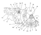
図1に示されているアラーム機構は従来からあるタイムピースムーブメント中に配置されるが、明確さのために、通常の要素は図示していない。同様に、アラーム機構の部品がその上に組み立てられるプレートも図には示されていない。 Although the alarm mechanism shown in FIG. 1 is located in a conventional timepiece movement, the usual elements are not shown for clarity. Similarly, the plate on which the alarm mechanism components are assembled is not shown.
アラーム機構は、図2によりよく示されている作動システムを含み、該作動システムは単一の孔12を備えた単一のカム10を有しており、該カムは調速輪列に連結されると共に時計回りに回転する。このカムは24時間毎に1回転する。孔12は、後で記載する制御部材16のピン14と協働する。図示されていないバネがカム10にピン14を押し付ける力をかける。前記孔の回転方向後方の縁部は回転方向前方の縁部よりもわずかに高くなっており、爪17を形成している。
The alarm mechanism includes an actuation system that is better illustrated in FIG. 2, which has a single cam 10 with a single hole 12 that is connected to a governing wheel train. And rotate clockwise. This cam rotates once every 24 hours. The hole 12 cooperates with a
アラーム時刻を調節する従来からある装置によって、カム10は、着用者が設定したアラーム時刻に孔12がピン14の正面に来るように配置される。制御システムが単一のピンと単一の孔と協働させることによって、前記文献に記載されている、3つのピンと3つの孔とを一列に並べる必要のある伝統的なシステムに比べて大幅に正確さを向上させることができる。
With a conventional device for adjusting the alarm time, the cam 10 is positioned so that the hole 12 is in front of the
制御部材16は3本のアーム18、20及び22を有している。これらのアームは、1つの点Aを中心として回転可能に取り付けられる。第一アーム18の端部は前記ピン14を有しており、その末端は留め部材を形成する尖った角部15になっている。第二アーム20と第三アーム22とは屈曲部20aと22aとをそれぞれ備えており、その端部はそれぞれ指状体20bと22bとになっている。
The
アラーム機構はそれ自身の動力源を備えている。この動力源は、従来の方法で、人手によって、又は自動的に巻き上げられる香箱24で作られている。
The alarm mechanism has its own power source. This power source is made up of a
ムーブメントの縁端部にある点Bに、レバー26が回動可能に取り付けられる。該レバーの端部の内の第一端部26aは、前記香箱24を巻き上げた状態に維持する狼歯車28の歯止めを形成している。前記レバーの第二端部において、レバー26は屈曲部20aと協働するためのピン26bを有している。
A
前記レバー26は、さらに、アラーム機能停止状態において、計数カム32に形成された孔30内に配置されるピン26cを有している。なお、計数カムは、以下の記載より理解されるように、アラームの継続時間を決定するのを可能にすることから、そのように命名された。
The
既に記載した要素よりも低い位置にある歯車列は、香箱24を、計数カム32の下にあると共にその回転軸が同じである中間車に接続する。計数カムの下にあるので、この中間車は図においては見えていない。この中間車によって、回転軸が同じで重ね合わされた2つの車、即ち、該中間車と前記計数カム32とを、動力伝達可能に接続することを可能にする二重小歯車36を介して回転させることができる。好ましい一態様においては、二重小歯車36が前記中間車及び計数カム32と咬合する第一位置と咬合しない第二位置との間を動くことのできるレバー38に、該二重小歯車36が取り付けられる。
The gear train, which is lower than the elements already described, connects the
計数車32に加えて、計数手段は、前記中間車と咬合する車40を有する。車40は、その下に、前記第三アーム22の指状体22bと協働するハート・カム42を支持している。
In addition to the counting
このアラーム機構は、プレート上で回動する留め部材44も有している。この留め部材44は、特に、前記カム10の縁端部近傍に配置される鉤部46と、その役割については後述するピン48とを有している。
The alarm mechanism also includes a retaining member 44 that rotates on the plate. In particular, the fastening member 44 has a
ムーブメントの縁端部に、長いレバー50が回動可能に取り付けられている。このレバーは、アラーム時刻を修正する、従来型の制御棒と協働し、その2つの端部の1つが前記ピン48の近傍に配されている。
A
香箱24が回転すると、歯車列を介して、該香箱は時打機構を駆動する。この時打機構は、その歯が複数の爪52と協働して回転する星形車51を有している。この複数の爪は対応するハンマー54を作動し、澄んだ明るい音を発する鐘56を打つ。ハンマー54は、通常、図示されていないバネと逆バネとを有している。従来から、図示されていない慣性式ブレーキが動力伝達可能に香箱に接続されており、その巻き戻りとハンマーによる時打の周波数を調節している。
When the
好適な一態様において、特許出願EP 05102567.4号に記載されているように、複数の爪52は同一の軸上に配置される。より詳しくは、爪の各々は、
−前記星形車51と協働して爪を回動させるための鉤部52a、
−前記爪をアラーム機能停止位置に保つための、図示されていないバネを有する、位置決め面52b、及び
−ハンマー54が有するピンに直接作用して、ハンマーに鐘56を打たせる爪部52c
を有している。
In a preferred embodiment, the plurality of
-
A
have.
以下の記載より理解されるように、その構造故に、星形車51の形状、特に厚さに応じて、複数の爪は別々に動作することもできるし、また、同時に動くこともできる。この星形車が爪2つを動かすことができる厚さを有していれば、対応する鉤部の相対的な位置によってハンマーを打つ間隔を調節することができる。
As will be understood from the following description, due to the structure, the plurality of claws can be operated separately or can be moved simultaneously depending on the shape of the
前記慣性式ブレーキは、計数カム32の回転の継続を間接的に制御する。計数カムは、約20秒で1回転し、以下の記載からよりよく理解されるように、これによってアラームの継続時間が決定される。
The inertia brake indirectly controls the continuation of the rotation of the
(単純なアラームの動作)
そのアラーム機能停止位置において、レバー26は香箱24の動きを止め、巻き上がった状態にしておく。プログラムされたアラーム時刻に、孔12がピン14の正面に到達する。先に記載したバネによって、ピン14は孔内に落ち、制御部材16が時計回り方向に傾斜する。屈曲部20aがピン26bを押してレバー26を回動させ、時打香箱の巻き戻り停止状態を解除する。そして、計数カム32の孔30からピン26cを除去する。香箱24は時打機構、特に、星形車51を駆動して、時計の着用者にプログラムされていた時刻になったことを知らせる。
(Simple alarm operation)
At the alarm function stop position, the
さらに、香箱は、歯車列を介して計数カム32と二重小歯車36とを駆動する。ピン26cは計数カムの回転中、計数カムの縁端部に当接しており、これによってレバー26が持ち上げられた状態になり、香箱の巻き戻り停止が解除された状態が維持される。
Further, the barrel moves the
計数車32の回転によって、車40とハート・カム42とが時計回り方向に駆動される。これによって、指状体22bが押され、制御部材16が反時計回りに回動する。すると、ピン14が孔12から持ち上げられ、第二アーム20がピン26bから離れる。
The rotation of the
カム10が未だ十分に回転していない場合は、不適切な時点でピン14が孔12内に戻ってしまうのを避けるために、その角部15が留め部材44にしっかりと係留されるまで、第一アーム18が回動する。
If the cam 10 has not yet rotated sufficiently, until its corner 15 is securely anchored to the retaining member 44 to avoid the
計数カム32が1回転すると、ピン26cは孔30内に戻る。持ち上げられていたレバー26は元の位置に戻り、その端部26aは再び香箱の巻き戻りを停止してアラームを止める。
When the
一方、カム10は回転を続け、爪17が留め部材44の鉤部と交差することによって、第一アーム18の角部15を回転させて前記留め部材から解放する。ピン14はカム10の縁部に戻り、24時間後に再び孔内に落ち込む準備ができる。
On the other hand, the cam 10 continues to rotate, and the
第一のアラームの直後に、角部15がまだ留め部材44に係留されている間に、時計の使用者が、再び時打をさせるためにアラーム時刻を修正したい場合は、まず、角部15を解放してピン14が再び孔12内に落ち込むことができるようにする必要がある。アラーム時刻を変更するためには、使用者は制御棒を引かなくてはならない。制御棒が引かれると、ピン48を押しているレバーを動かして、留め部材44が回動される。角部15は解放され、前記ピンがカム10上に戻り、孔12内に落ち込むのを待機する。
Immediately after the first alarm, while the corner 15 is still moored to the fastening member 44, if the watch user wants to correct the alarm time to make it hit again, first the corner 15 Must be released so that the
(マルチモード及び振動装置(図3))
アラーム時打機構を停止して、「サイレント」と称されるモードにすることができると好ましい。同様に、特定の一態様においては、アラーム機構が「消音」と称されるモードで動作する、即ち、前記鐘及びハンマーを動作させることなく、音のしない物、例えば、ケースの背面に取り付けられたピン72を打つハンマー70を動作させるのを可能にする装置を含んでいる。
(Multimode and vibration device (Fig. 3))
Preferably, the alarm beating mechanism can be stopped to enter a mode called “silent”. Similarly, in one particular aspect, the alarm mechanism operates in a mode referred to as "silence", i.e., it is mounted on the back of a case without sound without operating the bell and hammer. It includes a device that enables the
これらのモードの一方又は他方を選択して対応する機能を作動させるためには、着用者が作動モードを選択しなければならない。この選択は、単一の回転軸Cに取り付けられている複数のカムを重ね合わせることによってなされる。当業者によって選択される制御部材によって、着用者はこの回転軸Cを回転させて一方又は他方のカムを動作状態にする。 In order to select one or the other of these modes and activate the corresponding function, the wearer must select the operation mode. This selection is made by overlapping a plurality of cams attached to a single rotation axis C. By means of a control member selected by a person skilled in the art, the wearer rotates this axis of rotation C and puts one or the other cam into operation.
サイレントモードを作動させることのできるカム74は丸く、2本のピン76を有している。これらのピン76は第二アーム20の指状体20bと協働して制御部材16が回転するのを防ぎ、これによってピン14が孔12内に入り込まない状態を維持する。サイレントモードが選択された時には、前記2本のピン76の一方は前記指状体20bと接触する位置に配置されている。他方のピン76は、着用者がアラーム時刻を調節したときのセーフティーを構成する。実際、ある特定のモードの必要性はアラーム時刻の調節に帰し、アラーム時刻が現在時刻と交差したときに適時でない時打を避けることを可能にする。
The
消音モードを作動させることのできるカム78は丸く、凹部78aを有している。
The
この態様においては、香箱24を星形車51に接続する歯車列は、香箱に直接取り付けられたスライディング・ピニオン80を有する。このスライディング・ピニオン80は、点Dを中心として回動する第一レバー82の一端に取り付けられている。感知アーム84が第一レバー82と連結させて組み立てられており、カム78と協働する。
In this embodiment, the gear train that connects the
バネ85がプレートに固定されており、前記感知アーム84をカム78に当接させることを目的として、第一レバー82に力をかけている。
A
第二レバー86が、その複数の端部の内の第一端部によって、前記第一レバー82に回転可能に取り付けられている。第二レバーは、第一レバー82の長さ方向に向いた長円形の開口部88を備えている。プレートに取り付けられた1本のピン90が、該開口部88にその位置を占めている。第二レバー86の第二端部には小歯車92が取り付けられており、以下の記載より理解されるように、該小歯車は、2本のレバー82と86の動きを合わせた動きによって、スライドさせられる。このスライドする小歯車92は、前後動カム94の小歯車と永久的に咬合する。
A
前後動中間車96は、その片側に2本の歯96aを有するフォーク形部材を備え、もう一方の側には鉤爪の形状に配置された2本の堅いアーム96bを備えている。この前後動中間車96は、前記2本のアーム96bの交点で回転可能にプレートに取り付けられている。これらのアームの内の一方のアームの端部、そして他方のアームの端部がカム94と協働し、該中間車96を一方向、次いで他方向に傾斜させて、その発振動を前記フォーク形部材96aに伝える。
The longitudinally moving
ハンマー70は、その回転中心から外れた位置に、前記フォーク96aの2本の歯の間に打ち込まれたピン97を有している。したがって、フォーク96aの振動はハンマーに伝えられ、ハンマーはピン72を打つ。ハンマー70のバネ(図示せず)は、カム94と接触する2本のアーム96bの戻りを強くすることによって、振動を容易にする。
The
香箱と直接的に咬合する歯車列は、点Dを中心として回転する歯車98を経て、小歯車92の近傍で終わる。
The gear train that meshes directly with the barrel completes in the vicinity of the
さらに、振動モードが作動されると、通常のアラームとの接続を断つ必要があることが理解される。図1bに示されているように、この態様においては、星形車51はレバー100に取り付けられている。その歯が前記複数の爪52と協働することができるように、バネ101が停止部材102に対してレバー100を押し付けている。
Furthermore, it will be appreciated that when the vibration mode is activated, it is necessary to disconnect from the normal alarm. In this embodiment, the
前記停止部材102は、ムーブメントの縁端部に配置されているまた別のレバー104の端部によって形成されている。感知アーム106を形成する、レバー104の端部の他端は、軸Cに取り付けられたカムと協働する。通常のアラームが作動状態にあるとき、感知アーム106は該カムの窪んだ部分にあり、レバー104によって、前記バネが星形車51を複数の爪52と接触するように押している。
The
一方、消音モードにおいては、感知アーム106は前記カムの窪みのない部分にあり、レバー104はバネ101に力を加えて、前記複数の爪と接触しないように星形車51を押す。同時に、感知アーム84はカム78の凹部78aに押し込まれてレバー80が回転し、前記スライディング・ピニオン80を香箱24から外す。第二レバー86が回転し、前記開口部88が接触して滑動する前記ピン90の効果によって、前記スライドする小歯車92が相対的に前進して前記歯車98と咬合する。
On the other hand, in the silence mode, the
現在時刻がアラーム用にプログラムされた時刻を示すと、先に説明したように時打用香箱が解放される。そして、ブレーキが解除されているので、時打用香箱は歯車98を回転させて、ハンマー70を高周波数で動作させて振動を起こす。星形車51も回転させられるが、前記複数の爪52と交差しないので、鐘が音を出すことはない。
When the current time indicates the time programmed for the alarm, the hourglass barrel is released as described above. Since the brake is released, the hourglass barrel rotates the
(動作中のアラームの停止)
アラーム機構は、動作中にアラームを停止するのを可能にする装置を有している。この装置は、図1aと図4とに示されている。該装置は、時計のケースの中央部、例えば10時の位置に収容されているボタンを有している。このボタンは並列に取り付けられた設定車112に直接接続されている。この設定車の端部には第一指状体114と第二指状体116とが設けられており、前者はピン114aを、後者はピン116aを備えている。
(Stop alarm during operation)
The alarm mechanism has a device that makes it possible to stop the alarm during operation. This device is shown in FIGS. 1a and 4. FIG. The device has a button housed in the central part of the watch case, for example at the 10 o'clock position. This button is directly connected to the
このピン114aは、レバー38が有する傾斜面118と接触する位置にある。この傾斜面118は、前記設定車112が動くときにピン114aによって与えられる力によって、該レバーをその第一の位置に動かすように、即ち、当該レバーが中間設定車と計数カム32とから離れるように傾斜している。
The
前記ピン116aは、プレートに回動可能に取り付けられたレバー120の近傍に配置されており、該レバーの端部の内の第一端部120aに作用するようになっている。その第二端部120bの近傍では、このレバー120はハート・カム42の高さに位置している。アラーム機能停止位置において、レバー120は前記ハート・カムの2つの肩部に接触しており、これによって、ハート・カム42の安定した位置を定めている。計数カム32は、ハート・カム42がその安定した位置にあるときに、ピン26cが孔30の正面にあるように配置されている。
The pin 116a is disposed in the vicinity of the
当業者には知られていることであるが、ハート・カムがその安定した位置にない場合には、前記レバー120によってかけられる押圧力によってハート・カムをその初期の位置に自動的に戻す。この押圧力は、設定車112が動くときに得られ、レバー120をゆっくりと動かしてハート・カム42に当接させる。
As is known to those skilled in the art, when the heart cam is not in its stable position, the pressing force applied by the
このように、アラームの継続中に着用者がアラームを停止したい場合には、ボタン110を押すことによって設定車112の前記並進動を惹起することができる。
As described above, when the wearer wants to stop the alarm while the alarm continues, the translation of the
先に説明したように、次いで、ピン114aはレバー38に力を及ぼして、レバー38を計数カム32から外す。これによって、計数カムの回転は停止され、ピン26cが計数カム32の縁端部に当接する。この状態では、時打用香箱の巻き戻し動は停止されないままである。
As previously described, the
同時に、ピン116aがレバー120に力をかけ、これによってハート・カム42がその安定した位置に戻る。車40と前記中間車とを介して、アラーム機能停止位置にあっても、計数カム32は駆動される。次いで、ピン26cが孔30内に戻る。すると、レバー26が回動し、その端部26aが歯止め用車28と香箱24の巻き戻りを停止する。
At the same time, the pin 116a applies a force to the
言うまでもなく、バネ又は他の弾性システムが設定車を初期の位置に戻す。図示されていないバネの影響によって、レバー38は、前記二重小歯車36が前記中間車と計数カム32と咬合する、その通常の位置を再び占める。
Needless to say, a spring or other elastic system returns the setting wheel to its initial position. Under the influence of a spring (not shown), the
(現在時刻の調整中のセーフティー)
先に記載したように、携帯時計の着用者がアラーム時刻を調節し、この時刻が現在時刻と交差するとき、ある装置がアラームが作動されるのを防ぐ。同様に、着用者が現在時刻を調節し、この時刻がアラーム時刻と交差するときにもアラームを停止することが望ましい。
(Safety during adjustment of the current time)
As described above, the wearer of the portable watch adjusts the alarm time, and when this time crosses the current time, certain devices prevent the alarm from being activated. Similarly, it is desirable to stop the alarm when the wearer adjusts the current time and this time crosses the alarm time.
これを行うために、レバー50が前記制御部材16の第三アーム22の近くを通過する。より詳しくは、このレバーは、屈曲部22aの高さに位置するピン50aを備えており、該屈曲部と協働することができる。通常の動作においては、ピン50aは制御部材16の移動を妨げない。しかしながら、着用者が現在時刻を調節するために制御棒を引くと、レバー50が動かされてピンが屈曲部22aと接触するようになる。このような機構において、時刻の調節中にこの時刻がアラーム時刻と交差しても、前記ピンが制御部材16が回転するのを妨げるので、ピン14は孔内に入ることができない。
To do this, the
(ミニッツ・リピーター機構付きアラーム)
図4に示されているある特定の態様において、ここまで記載してきたアラーム機構が、例えば先にも言及した出願に記載されているもののような、ミニッツ・リピーター機構と連結される。ある種の変更は当業者には明らかであり、詳細に記述する必要はない。
(Alarm with minute repeater mechanism)
In one particular embodiment shown in FIG. 4, the alarm mechanism described so far is coupled to a minute repeater mechanism, such as that described in the above-referenced application. Certain modifications will be apparent to those skilled in the art and need not be described in detail.
このようにして、2つの機構は、前記慣性式ブレーキによって律せられている同一の時打用香箱24から、その駆動力を得る。時打用香箱は、やはり、レバー26によって巻き戻りの停止と停止解除とが行われる。ミニッツ・リピーター機構が動作中は、レバー26は、ミニッツ・リピーター機構が動作中に回動するレバー50に配設されている留め部材50cによって持ち上げられる。
In this way, the two mechanisms obtain their driving force from the same
アラーム機構と同様に、ミニッツ・リピーター機構も計数カム121を有している。このカムは2つの孔を備えており、前記計数車32と同じ回転軸に取り付けられている。前記レバー38は、前記二重小歯車36に加えて、前記中間車をミニッツ・リピーター機構の計数カムの中間車に動力伝達可能に接続する第二の二重小歯車36bを備えている。このようにすると、静止位置において、レバー38はその第一の位置にあり、二重小歯車36によって、アラーム機構の計数カム32を駆動することが可能になる。ミニッツ・リピーター機構が作動されると、レバー50に設けられた留め部材50cが、該レバーをその第二の位置に戻す。すると、二重小歯車36bがミニッツ・リピーター機構の計数カムを駆動することが可能になる。
Similar to the alarm mechanism, the minute repeater mechanism also has a
これら2つの機構は、時打機構、特に鐘56及びハンマー54も共有する。しかしながら、やはり同じ回動軸に取り付けられた3つの爪52がある。
These two mechanisms also share the time-striking mechanism, in particular the
上方の爪と下方の爪とは全く同じであり、十分な大きさのハンマーに連結されたピンを介して、両者は同じハンマーに作用する。上方の爪は、ミニッツ・リピーター機構の、時用の歯が設けられた部分と1/4時(15分)用の歯が設けられた部分とによって動かされる。下方の爪はアラーム機構の星形車51によって動かされる。中間にある爪は、ミニッツ・リピーター機構の時用の歯が設けられた部分及び1/4時(15分)用の歯が設けられた部分と、星形車51との両方によって動かされる。
The upper and lower claws are exactly the same, and both act on the same hammer via a pin connected to a sufficiently large hammer. The upper pawl is moved by the part of the minute repeater mechanism with the hour teeth and the quarter hour (15 minutes) teeth. The lower claw is moved by the
さらに、アラーム機構が消音モードであるときに、使用者がミニッツ・リピーター機構を作動させたい場合は、装置が前記慣性式ブレーキと係合することが必須の要件となる。これは、レバー50と連結されると共に、スライディング・ピニオン80に当接していないレバー82の端部と協働する棒122を用いて行われる。
Furthermore, if the user wants to activate the minute repeater mechanism when the alarm mechanism is in the mute mode, it is an essential requirement that the device engages the inertial brake. This is done using a
使用者がボタン110を押してミニッツ・リピーター機構を作動させると、レバー50が回動し、前記棒122がレバー82の端部を押す。すると、このレバー82は回動し、スライドする小歯車92を振動用の機構から離すと共にスライディング・ピニオン80を前記慣性式ブレーキに咬合させる。このようにして、ミニッツ・リピーター機構は正常に音を出すことができる。
When the user presses the
このようにして、導入部で記載した欠点のないアラーム機構が提案される。この明細書は情報を与えるためにのみに記載されており、余すところなく記載されてはいない。実際、当業者であれば、先に提供された技術的な説明を労することなく適切に使用して、例えば、消音モードのアラームのみを有するアラーム機構を作ることができる。この消音モード中に、前記慣性式ブレーキの係合を解除する必要もない。当業者であれば、前記慣性式ブレーキが常に係合した状態にある単純化された機構を提供することもできる。要すれば、ミニッツ・リピーター機構の作動時に、このブレーキを再係合させる必要もない。同様に、アラームの継続時間を制御するのに、カムと感知アームとのシステム、又はピンと孔との組み合わせの他の同等物を採用するなど、他の方法を使用することができるのも明らかである。さらに、カム10が24時間xn回毎に1回転する速度で駆動される場合は、該カム10は、その縁部に規則的に分配されたn個の孔を有していてもよい。 In this way, an alarm mechanism without the drawbacks described in the introduction is proposed. This specification is provided for informational purposes only and is not exhaustive. In fact, those skilled in the art can make appropriate use of the technical description provided above without effort, for example, to create an alarm mechanism having only a mute mode alarm. It is not necessary to release the engagement of the inertial brake during the silencing mode. One skilled in the art can also provide a simplified mechanism in which the inertia brake is always engaged. If necessary, it is not necessary to reengage the brake when the minute repeater mechanism is operated. Similarly, it should be apparent that other methods can be used to control the duration of the alarm, such as employing a cam and sensing arm system or other equivalent of a pin and hole combination. is there. Furthermore, if the cam 10 is driven at a speed of one revolution every 24 hours xn times, the cam 10 may have n holes regularly distributed at its edges.
Claims (6)
−アラーム時刻をプログラムするのに使用することのできる調節システム、及び
−前記動力源の動作停止の解除を制御する制御部材(16)と、ムーブメントに動力伝達可能に接続されると共に24時間毎に1回転するカム(10)とを有する作動システム
を含むアラーム機構であって、該アラーム機構が、少なくとも1つの鐘(56)を打つための少なくとも1つのハンマー(54)を備えた第一時打機構と、少なくとも1つの音を立てない物(72)を打つための少なくとも1つのハンマー(70)を備えた第二時打機構とを備え、前記アラーム機構が、前記少なくとも1つの鐘(56)を打つことによって前記第一時打機構により、又は前記少なくとも1つの音を立てない物を振動装置を介して打つことによって前記第二時打機構によりアラームを報知し、前記動力源が(24)第一又は第二時打機構を駆動するアラーム機構を備えるタイムピース。A power source (24) that is deactivated when the alarm mechanism is in an inoperative state and is deactivated during operation of the alarm mechanism;
An adjustment system that can be used to program the alarm time, and a control member (16) that controls the release of the power source deactivation and is connected to the movement in a power-transmittable manner and every 24 hours An alarm mechanism comprising an actuating system having a rotating cam (10), the alarm mechanism comprising at least one hammer (54) for striking at least one bell (56); And a second time striking mechanism with at least one hammer (70) for striking at least one non-sounding object (72) , wherein the alarm mechanism comprises the at least one bell (56) An alarm is notified by the first time striking mechanism by hitting or by the second time striking mechanism by hitting the at least one non-sounding object through a vibration device , (24) A timepiece having an alarm mechanism for driving the first or second time striking mechanism.
Applications Claiming Priority (3)
| Application Number | Priority Date | Filing Date | Title |
|---|---|---|---|
| EP05102568A EP1708051A1 (en) | 2005-03-31 | 2005-03-31 | Timepiece comprising an alarm |
| EP05102568.2 | 2005-03-31 | ||
| PCT/EP2006/061239 WO2006103289A2 (en) | 2005-03-31 | 2006-03-31 | Timepiece comprising an alarm |
Publications (2)
| Publication Number | Publication Date |
|---|---|
| JP2008534942A JP2008534942A (en) | 2008-08-28 |
| JP5097105B2 true JP5097105B2 (en) | 2012-12-12 |
Family
ID=35756134
Family Applications (1)
| Application Number | Title | Priority Date | Filing Date |
|---|---|---|---|
| JP2008503529A Expired - Fee Related JP5097105B2 (en) | 2005-03-31 | 2006-03-31 | Timepiece with alarm mechanism |
Country Status (5)
| Country | Link |
|---|---|
| US (2) | US7742362B2 (en) |
| EP (2) | EP1708051A1 (en) |
| JP (1) | JP5097105B2 (en) |
| RU (1) | RU2007140325A (en) |
| WO (1) | WO2006103289A2 (en) |
Families Citing this family (23)
| Publication number | Priority date | Publication date | Assignee | Title |
|---|---|---|---|---|
| EP2017682A3 (en) | 2007-07-19 | 2010-10-06 | Turlen Holding SA | Alarm module for a timepiece |
| EP2214065B1 (en) * | 2008-12-01 | 2017-02-08 | The Swatch Group Research and Development Ltd. | Timepiece movement equipped with a vibrating alarm |
| EP2339413B1 (en) * | 2009-12-22 | 2012-09-12 | The Swatch Group Research and Development Ltd. | Timepiece movement equipped with a vibrating alarm |
| CH702424A1 (en) * | 2009-12-24 | 2011-06-30 | Montres Breguet Sa | striking mechanism of a watch. |
| EP2363764B1 (en) * | 2010-03-05 | 2015-09-16 | Montres Breguet SA | Device for sequentially controlling at least two lifts of a timepiece mechanism |
| EP2367076B1 (en) * | 2010-03-17 | 2018-08-08 | Glashütter Uhrenbetrieb GmbH | Alarm device suitable for being set 30 days in advance |
| CH703406B1 (en) * | 2010-07-08 | 2015-04-30 | Complitime Sa | Timepiece including a striking mechanism. |
| CH704392A1 (en) * | 2011-01-28 | 2012-07-31 | Montres Breguet Sa | striking mechanism of a hammer lock watch. |
| CH704626A2 (en) * | 2011-03-08 | 2012-09-14 | Montres Breguet Sa | Striking block for alarm clock strike driving mechanism of e.g. instantaneous triggering type grand strike mechanism of wristwatch, has wheel and detent ratchet that co-operate with hook to authorize transfer of energy to sound mechanism |
| EP2498146B1 (en) * | 2011-03-08 | 2018-07-18 | Montres Breguet SA | Grande sonnerie wake-up alarm mechanism |
| EP2498149B1 (en) * | 2011-03-08 | 2015-07-01 | Montres Breguet SA | Duration limiter mechanism for timepiece mechanism |
| EP2498143B1 (en) * | 2011-03-08 | 2018-05-02 | Montres Breguet SA | Isolation mechanism between timepiece mechanisms for setting off different acoustic signals |
| CH704672A2 (en) | 2011-03-22 | 2012-09-28 | Montres Breguet Sa | Selective stop mechanism for striking work of watch, has isolation mobile for controlling position of blocking lever and releasing/prohibiting movement of striking work control rod and/or authorizing/prohibiting impact of hammer on gong |
| EP2615503B1 (en) * | 2012-01-13 | 2014-09-24 | Agenhor SA | Barrel control mechanism for timepiece movement |
| CN103425039B (en) * | 2012-05-25 | 2016-01-27 | 天津海鸥表业集团有限公司 | Automatically alarming in a kind of stem-winder starts control structure |
| EP2808745B1 (en) * | 2013-05-28 | 2019-07-03 | Montres Breguet SA | Striking mechanism provided with means for selecting chime vibration mode |
| CH710189A1 (en) * | 2014-09-23 | 2016-03-31 | Complitime Sa | striking mechanism. |
| EP3339976A1 (en) * | 2016-12-23 | 2018-06-27 | Blancpain SA | Mechanical watch with repeater |
| EP3435169B1 (en) * | 2017-07-25 | 2023-03-01 | Blancpain SA | Halting mechanism for a timepiece chiming mechanism |
| EP3502801B1 (en) * | 2017-12-19 | 2021-02-17 | Omega SA | Chronograph repetition mechanism with safety |
| EP3502802B1 (en) * | 2017-12-19 | 2021-02-17 | Omega SA | Chronograph repetition mechanism with safety |
| EP3547045B1 (en) * | 2018-03-26 | 2022-05-04 | Montres Breguet S.A. | Timepiece transmission mechanism having reduced clutching effort |
| EP3575886B1 (en) * | 2018-05-28 | 2021-03-10 | Blancpain SA | Timepiece with striking mechanism and safety trigger |
Family Cites Families (19)
| Publication number | Priority date | Publication date | Assignee | Title |
|---|---|---|---|---|
| US641475A (en) * | 1899-07-29 | 1900-01-16 | Enrique Torres | Repeating clock. |
| US916953A (en) | 1908-06-12 | 1909-03-30 | Henry A Lugrin | Watch for counting the pulse by sound or touch. |
| US1421801A (en) * | 1921-06-13 | 1922-07-04 | Waltham Watch Co | Repeater timepiece |
| US2034945A (en) * | 1933-11-07 | 1936-03-24 | Frank W Haderman | Striking attachment for clocks |
| CH289113A (en) * | 1950-11-30 | 1953-02-28 | Froidevaux Jean Michel | Alarm clock. |
| FR1166133A (en) * | 1956-01-21 | 1958-11-03 | Clockwork piece with alarm clock | |
| US3732686A (en) | 1972-08-10 | 1973-05-15 | Schild Sa A | Watch movement including alarm mechanism |
| DE2334236C2 (en) * | 1973-07-05 | 1975-07-10 | Timex Corp., Waterbury, Conn. (V.St.A.) | Acoustic signal transmitter for clocks, in particular wristwatches |
| US4135474A (en) * | 1977-09-15 | 1979-01-23 | Ruth Kaplan | Bell actuating mechanism |
| CH626497B (en) * | 1977-11-07 | Ebauches Sa | WATCH EQUIPPED WITH A RESONATOR SHAPED BY ITS ICE SUBJECT TO THE ACTION OF A TRANSDUCER. | |
| CH630220B (en) * | 1978-11-10 | Ebauches Sa | WATCH INCLUDING A BOX CLOSED BY A GLASS AND AN ELECTRO-ACOUSTIC DEVICE. | |
| DE3323420C2 (en) * | 1983-06-29 | 1986-10-16 | Joseph Kieninger Uhrenfabrik GmbH, 7209 Aldingen | Striking mechanism clock with device to switch off the striking mechanism |
| CH692067A5 (en) * | 1998-03-24 | 2002-01-15 | Nardin Ulysse Sa | Piece equipped with an alarm watch. |
| JP2001153976A (en) * | 1999-11-30 | 2001-06-08 | Rhythm Watch Co Ltd | Clock |
| JP3648148B2 (en) * | 2000-10-27 | 2005-05-18 | リズム時計工業株式会社 | Clock device |
| US7070320B2 (en) * | 2001-03-21 | 2006-07-04 | Glashütter Uhrenbetrieb GmbH | Mechanism for triggering a striking work for a timepiece fitted with a timer |
| DE60210955T2 (en) * | 2002-08-27 | 2007-05-24 | Frederic Piguet S.A. | Watch, especially wristwatch, with a wake-up mechanism |
| CH698533B1 (en) * | 2005-03-11 | 2009-08-31 | Richemont Int Sa | Device for fixing at least one ringing tone in a timepiece and a method of attaching at least one ringing tone in a timepiece. |
| EP1708050B1 (en) | 2005-03-31 | 2008-05-14 | Zenith International SA | Timepiece with a minute-repeater mechanism |
-
2005
- 2005-03-31 EP EP05102568A patent/EP1708051A1/en not_active Withdrawn
-
2006
- 2006-03-31 JP JP2008503529A patent/JP5097105B2/en not_active Expired - Fee Related
- 2006-03-31 EP EP06725485A patent/EP1869529A2/en not_active Withdrawn
- 2006-03-31 WO PCT/EP2006/061239 patent/WO2006103289A2/en active Application Filing
- 2006-03-31 RU RU2007140325/28A patent/RU2007140325A/en not_active Application Discontinuation
- 2006-03-31 US US11/910,105 patent/US7742362B2/en not_active Expired - Fee Related
-
2010
- 2010-05-07 US US12/776,128 patent/US7881161B2/en not_active Expired - Fee Related
Also Published As
| Publication number | Publication date |
|---|---|
| JP2008534942A (en) | 2008-08-28 |
| US20080273426A1 (en) | 2008-11-06 |
| WO2006103289A3 (en) | 2007-01-04 |
| WO2006103289A2 (en) | 2006-10-05 |
| EP1708051A1 (en) | 2006-10-04 |
| US7742362B2 (en) | 2010-06-22 |
| US7881161B2 (en) | 2011-02-01 |
| EP1869529A2 (en) | 2007-12-26 |
| US20100214884A1 (en) | 2010-08-26 |
| RU2007140325A (en) | 2009-05-10 |
Similar Documents
| Publication | Publication Date | Title |
|---|---|---|
| JP5097105B2 (en) | Timepiece with alarm mechanism | |
| JP5203182B2 (en) | Timepiece with minute repeater function | |
| US7965585B2 (en) | Ringing mechanism | |
| JP5467118B2 (en) | Hitting mechanism that emits different beating sounds | |
| US7293911B2 (en) | Timekeeper with a mechanism for measuring settable predetermined periods | |
| JP5374571B2 (en) | Quick corrector for indicators that display time-related magnitudes for watches | |
| US8873347B2 (en) | Mechanism for isolating timepiece mechanisms which release various acoustic signals | |
| US8588035B2 (en) | Safety mechanism protecting against inadvertent actuations of the minute repeater | |
| US8565045B2 (en) | Striking mechanism unit and drive mechanism for an alarm striking mechanism for a striking timepiece | |
| US8599651B2 (en) | Alarm strike using the grand strike | |
| US8570841B2 (en) | Duration limiting mechanism for a timepiece mechanism | |
| JP4612277B2 (en) | Watch with time | |
| US7717616B2 (en) | Timepiece with an hour hand able to be moved forward or backward by one hour step | |
| JP2019105630A (en) | Torque smoothing for timepiece, in particular, timepiece with strike mechanism | |
| JP6644124B2 (en) | Repeater mechanism with stretched chains | |
| US11188031B2 (en) | Timepiece with striking mechanism and release-prevention device | |
| JP4759217B2 (en) | Time-starting mechanism for watches equipped with a timer | |
| JP3648148B2 (en) | Clock device | |
| US2974473A (en) | Ship's bell clock | |
| US3475900A (en) | Alarm control mechanism | |
| JP2001153976A (en) | Clock |
Legal Events
| Date | Code | Title | Description |
|---|---|---|---|
| A621 | Written request for application examination |
Free format text: JAPANESE INTERMEDIATE CODE: A621 Effective date: 20090216 |
|
| A711 | Notification of change in applicant |
Free format text: JAPANESE INTERMEDIATE CODE: A712 Effective date: 20100806 |
|
| A977 | Report on retrieval |
Free format text: JAPANESE INTERMEDIATE CODE: A971007 Effective date: 20110819 |
|
| A131 | Notification of reasons for refusal |
Free format text: JAPANESE INTERMEDIATE CODE: A131 Effective date: 20110902 |
|
| A601 | Written request for extension of time |
Free format text: JAPANESE INTERMEDIATE CODE: A601 Effective date: 20111129 |
|
| A602 | Written permission of extension of time |
Free format text: JAPANESE INTERMEDIATE CODE: A602 Effective date: 20111206 |
|
| A601 | Written request for extension of time |
Free format text: JAPANESE INTERMEDIATE CODE: A601 Effective date: 20111228 |
|
| A602 | Written permission of extension of time |
Free format text: JAPANESE INTERMEDIATE CODE: A602 Effective date: 20120111 |
|
| A521 | Request for written amendment filed |
Free format text: JAPANESE INTERMEDIATE CODE: A523 Effective date: 20120131 |
|
| A131 | Notification of reasons for refusal |
Free format text: JAPANESE INTERMEDIATE CODE: A131 Effective date: 20120420 |
|
| A521 | Request for written amendment filed |
Free format text: JAPANESE INTERMEDIATE CODE: A523 Effective date: 20120719 |
|
| TRDD | Decision of grant or rejection written | ||
| A01 | Written decision to grant a patent or to grant a registration (utility model) |
Free format text: JAPANESE INTERMEDIATE CODE: A01 Effective date: 20120831 |
|
| A01 | Written decision to grant a patent or to grant a registration (utility model) |
Free format text: JAPANESE INTERMEDIATE CODE: A01 |
|
| A61 | First payment of annual fees (during grant procedure) |
Free format text: JAPANESE INTERMEDIATE CODE: A61 Effective date: 20120921 |
|
| R150 | Certificate of patent or registration of utility model |
Free format text: JAPANESE INTERMEDIATE CODE: R150 |
|
| FPAY | Renewal fee payment (event date is renewal date of database) |
Free format text: PAYMENT UNTIL: 20150928 Year of fee payment: 3 |
|
| R250 | Receipt of annual fees |
Free format text: JAPANESE INTERMEDIATE CODE: R250 |
|
| LAPS | Cancellation because of no payment of annual fees |