JP5096852B2 - Line width measuring apparatus and inspection method of line width measuring apparatus - Google Patents
Line width measuring apparatus and inspection method of line width measuring apparatus Download PDFInfo
- Publication number
- JP5096852B2 JP5096852B2 JP2007242361A JP2007242361A JP5096852B2 JP 5096852 B2 JP5096852 B2 JP 5096852B2 JP 2007242361 A JP2007242361 A JP 2007242361A JP 2007242361 A JP2007242361 A JP 2007242361A JP 5096852 B2 JP5096852 B2 JP 5096852B2
- Authority
- JP
- Japan
- Prior art keywords
- measurement
- focus area
- line width
- focus
- height
- Prior art date
- Legal status (The legal status is an assumption and is not a legal conclusion. Google has not performed a legal analysis and makes no representation as to the accuracy of the status listed.)
- Active
Links
Images


Classifications
-
- G—PHYSICS
- G01—MEASURING; TESTING
- G01B—MEASURING LENGTH, THICKNESS OR SIMILAR LINEAR DIMENSIONS; MEASURING ANGLES; MEASURING AREAS; MEASURING IRREGULARITIES OF SURFACES OR CONTOURS
- G01B21/00—Measuring arrangements or details thereof, where the measuring technique is not covered by the other groups of this subclass, unspecified or not relevant
- G01B21/02—Measuring arrangements or details thereof, where the measuring technique is not covered by the other groups of this subclass, unspecified or not relevant for measuring length, width, or thickness
- G01B21/04—Measuring arrangements or details thereof, where the measuring technique is not covered by the other groups of this subclass, unspecified or not relevant for measuring length, width, or thickness by measuring coordinates of points
- G01B21/045—Correction of measurements
-
- H—ELECTRICITY
- H01—ELECTRIC ELEMENTS
- H01L—SEMICONDUCTOR DEVICES NOT COVERED BY CLASS H10
- H01L22/00—Testing or measuring during manufacture or treatment; Reliability measurements, i.e. testing of parts without further processing to modify the parts as such; Structural arrangements therefor
- H01L22/10—Measuring as part of the manufacturing process
- H01L22/12—Measuring as part of the manufacturing process for structural parameters, e.g. thickness, line width, refractive index, temperature, warp, bond strength, defects, optical inspection, electrical measurement of structural dimensions, metallurgic measurement of diffusions
-
- H—ELECTRICITY
- H01—ELECTRIC ELEMENTS
- H01L—SEMICONDUCTOR DEVICES NOT COVERED BY CLASS H10
- H01L2924/00—Indexing scheme for arrangements or methods for connecting or disconnecting semiconductor or solid-state bodies as covered by H01L24/00
- H01L2924/0001—Technical content checked by a classifier
- H01L2924/0002—Not covered by any one of groups H01L24/00, H01L24/00 and H01L2224/00
Description
本発明は、パターン寸法を測定する測定装置に関わり、特に、平面状試料のパターン寸法を高精度に寸法測定を行う線幅測定装置の検査方法に関する。 The present invention relates to a measuring apparatus that measures a pattern dimension, and more particularly, to an inspection method for a line width measuring apparatus that measures a pattern dimension of a planar sample with high accuracy.
液晶表示パネル、等のFPD( Flat Panel Display )、半導体ウエーハ、若しくは、それらを製作するためのガラスマスク、等、平面状基板に形成されたパターンの線幅等の寸法を高精度に測定するための線幅測定装置は、近年、ワークサイズが大きくなる傾向にあり、かつ、パターンがより高精細になっていっている。LCD( Liquid Crystal Device )基板でも、その傾向が強く、LCD測定用の線幅測定装置(LCD線幅測定装置)では、基板の大型化及び高精細化に伴い、位置ずれ対策が重要となってきている。 To measure the line width and other dimensions of a pattern formed on a flat substrate, such as a liquid crystal display panel, flat panel display (FPD) such as a liquid crystal display panel, a semiconductor wafer, or a glass mask for manufacturing them. In recent years, the line width measuring apparatus tends to have a larger workpiece size, and the pattern is becoming more precise. Even LCD (Liquid Crystal Device) substrates have a strong tendency, and in line width measuring devices for LCD measurement (LCD line width measuring devices), countermeasures against misalignment have become important as the size and size of the substrates increase. ing.
LCD線幅測定装置等の線幅測定装置は、CCD( Charge Coupled Device )カメラ等、固体撮像素子を使ったカメラ搭載の光学顕微鏡ヘッド(以降、光学ヘッドと称する)を、被測定対象物のLCD基板の測定位置に移動させ、移動した位置の被写体像を撮像して、パターン認識により寸法測定を行う。
光学ヘッドを測定位置に移動させるためには、例えば、被測定対象物である基板を水平面(X−Y平面)上に固定し、光学ヘッドをX軸方向とY軸方向とに移動させる2軸構造とし、更に、光学ヘッドの合焦点のために高さ(Z軸)方向にも光学ヘッドを移動可能としている。
A line width measuring apparatus such as an LCD line width measuring apparatus uses a camera-mounted optical microscope head (hereinafter referred to as an optical head) using a solid-state imaging device such as a CCD (Charge Coupled Device) camera. The substrate is moved to the measurement position, the subject image at the moved position is captured, and the dimension is measured by pattern recognition.
In order to move the optical head to the measurement position, for example, a substrate that is a measurement target is fixed on a horizontal plane (XY plane), and the optical head is moved in the X-axis direction and the Y-axis direction. Further, the optical head can be moved also in the height (Z-axis) direction for the focal point of the optical head.
位置ずれの補正としては、例えば、特許文献1では、パターン認識によって位置ずれを検出し、測定箇所の位置ずれが大きい場合のみ、位置ずれを補正するために移動してから測定し、被測定箇所(測定位置)の位置ずれが小さい場合には、位置ずれを補正しないで測定している。
また、例えば、特許文献2では、レーザ変位計若しくはレーザ干渉計を用いて位置ずれを検出し、X軸方向とY軸方向のステージの移動量を補正している。
For example, in
For example, in Patent Document 2, a positional displacement is detected using a laser displacement meter or a laser interferometer, and the amount of movement of the stage in the X-axis direction and the Y-axis direction is corrected.
以下、添付図面を参照しながら従来技術を詳細に説明する。なお、各図において、共通な機能を有する部分には同一符号を付して、その重複する説明を省略する。 Hereinafter, the related art will be described in detail with reference to the accompanying drawings. In each figure, parts having common functions are denoted by the same reference numerals, and redundant description thereof is omitted.
先ず、従来の検査装置の一実施例を図1によって説明する。図1は、従来の一実施例の線幅測定装置の概略を示す斜視図である。
図1において、10は線幅測定装置、12はLCD基板等の基板、11は基板12を載置するステージ、13は光学ヘッド、14はY軸ステージ、15はX軸ステージ、16はX軸レール、17は定盤である。
線幅測定装置10において、ステージ11とX軸レール16は、定盤17の上に搭載されている。X軸レール16のレールに沿ってX軸方向に移動できるようにX軸ステージ15が搭載されている。また、X軸ステージ15に沿ってY軸方向に移動できるようにY軸ステージ14が搭載されている。そして、Y軸ステージ14に光学ヘッド13が取り付けられている。
光学ヘッド13は、Y軸ステージ14に取り付けられているために、Y軸方向に移動可能であると共に、Y軸ステージ14を介して間接的にX軸ステージ15上にあるため、X軸ステージ15が、X軸レール16上をX軸方向に移動することによって、X軸方向にも移動可能である。
このように、光学ヘッド13は、X軸ステージ15とY軸ステージ14がステージ11上をX軸方向若しくはY軸方向に移動することによって、ステージ11上に固定された基板12の任意の測定位置へ移動して、拡大画像を取得できる。
なお、光学ヘッド13は、Y軸ステージ14に高さ(Z軸)方向に移動可能に取り付けられているため、合焦点可能である。
First, an example of a conventional inspection apparatus will be described with reference to FIG. FIG. 1 is a perspective view showing an outline of a conventional line width measuring apparatus according to an embodiment.
In FIG. 1, 10 is a line width measuring device, 12 is a substrate such as an LCD substrate, 11 is a stage on which the
In the line
Since the
As described above, the
Since the
図2によって、従来の線幅測定装置のおおよその機構を更に説明する。図2は、従来の線幅測定装置を上方向から見た図である。なお、本願の説明に必要のない部分は図示せず、省略している。例えば、図1で説明したステージ11と定盤17は、図示していない。12は基板、13は光学ヘッド、14はY軸ステージ、15はX軸ステージ、及び、16はX軸レールで、図1と同様である。また、21はレーザ干渉計、22−1はLXAターゲットミラー、22−2はLXBターゲットミラー、23はLYターゲットミラー、24−2と25は反射ミラー、24−1と26はハーフミラー、27−1〜27−4、28−1と28−2、及び、29はレーザ光の通過経路を模式的に示した光路である。
The general mechanism of the conventional line width measuring apparatus will be further described with reference to FIG. FIG. 2 is a view of a conventional line width measuring device as viewed from above. In addition, the part which is not required for description of this application is not shown in figure and is abbreviate | omitting. For example, the stage 11 and the
図2において、ステージ(図示しない)上に固定された基板11の測定位置に光学ヘッド(例えばCCDカメラ搭載の光学顕微鏡)13を移動することにより、測定位置のパターンの座標(距離)を測定する。光学ヘッド13の水平方向の移動は、Xステージ15若しくはYステージ14の少なくとも1つを駆動することにより実行される。
この線幅測定装置においては、光学ヘッド13は、Y方向に移動するY軸ステージ14に取り付けられ、向かい合った2つのX軸ステージ15は、Y軸ステージ14の両端を支持して、移動するガントリー形式である。なお、Y軸ステージ14の左右の細い矢印は、Y軸ステージ14の移動方向を表わし、X軸ステージ15の上下の細い矢印は、X軸ステージ15の移動方向を表わしている。
In FIG. 2, the coordinate (distance) of the pattern of the measurement position is measured by moving the optical head (for example, an optical microscope equipped with a CCD camera) 13 to the measurement position of the substrate 11 fixed on a stage (not shown). . The horizontal movement of the
In this line width measuring apparatus, an
レーザ干渉計21は、LXAターゲットミラー22−1とLXBターゲットミラー22−2でX軸方向のステージの移動量を測定し、LYターゲットミラー23でY軸方向のステージの移動量を測定する。
即ち、レーザ干渉計から出力されるレーザ光は、光路29に沿ってハーフミラー26に到達し、ハーフミラー26で直進するレーザ光と0.5π[rad]の角度に反射するレーザ光とに分岐する。
ハーフミラー26で反射したレーザ光は、光路28−2に沿って反射ミラー27に到達し、反射ミラー25で0.5π[rad]の角度に反射する。反射ミラー25で反射したレーザ光は、光路28−1に沿ってLYターゲットミラー23に到達する。
LYターゲットミラー23に到達したレーザ光は、反射して、光路28−1、反射ミラー25、光路28−2、ハーフミラー26、及び、光路29を通ってレーザ干渉計21に戻る。
The
That is, the laser light output from the laser interferometer reaches the
The laser light reflected by the
The laser light that has reached the
また、ハーフミラー26から直進するレーザ光は、光路27−4に沿ってハーフミラー24−1に到達し、ハーフミラー24−1で直進するレーザ光と0.5π[rad]の角度に反射するレーザ光とに分岐する。
ハーフミラー24−1で反射したレーザ光は、光路27−1に沿ってLXAターゲットミラー22−1に到達する。
LXAターゲットミラー22−1に到達したレーザ光は、反射して、光路27−1、ハーフミラー24−1、光路27−4、ハーフミラー26、及び、光路29を通ってレーザ干渉計21に戻る。
ハーフミラー24−1で直進したレーザ光は、光路27−3に沿って反射ミラー24−2に到達し、0.5π[rad]の角度に反射する。
反射ミラー24−2で反射したレーザ光は、光路27−2に沿ってLXBターゲットミラー22−2に到達する。
LXBターゲットミラー22−2に到達したレーザ光は、反射して、光路27−2、光路27−3、ハーフミラー24−1、光路27−4、ハーフミラー26、及び、光路29を通ってレーザ干渉計21に戻る。
The laser light traveling straight from the
The laser beam reflected by the half mirror 24-1 reaches the LXA target mirror 22-1 along the optical path 27-1.
The laser beam that has reached the LXA target mirror 22-1 is reflected and returns to the
The laser light traveling straight by the half mirror 24-1 reaches the reflection mirror 24-2 along the optical path 27-3, and is reflected at an angle of 0.5π [rad].
The laser beam reflected by the reflection mirror 24-2 reaches the LXB target mirror 22-2 along the optical path 27-2.
The laser light that has reached the LXB target mirror 22-2 is reflected and laser passes through the optical path 27-2, the optical path 27-3, the half mirror 24-1, the optical path 27-4, the
光路27−1〜27−4、28−1、28−2、及び、29は、ほぼ同一の平面状になるように、レーザ干渉計21、LXAターゲットミラー22−1、LXBターゲットミラー22−2、LYターゲットミラー23、反射ミラー24−1及び25、並びに、ハーフミラー24−1及び26が検査装置上に設置されている。
また、レーザ干渉計21、ハーフミラー26、ハーフミラー24−1、及び、反射ミラー24−2は、それぞれ、設置された位置が固定されて相互の距離が予め分かっている。
また、反射ミラー25は、X軸ステージ15の移動に連動してLYターゲットミラー23と常にY軸方向と平行な位置とするため、図2では特に図示していないが、X軸ステージ15に搭載されている。
The
Further, the
The
図2に示すような配置で、レーザ干渉計21は、光路27−1及び光路27−2の距離の変位を検出してX軸ステージ15の移動した距離(移動量)を算出し、光路28−1の距離の変位を検出してY軸ステージ14の移動した距離(移動量)を算出する。
With the arrangement shown in FIG. 2, the
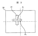
次に、各測定位置での位置ずれ量の検出について、図3を参照して説明する。図3は、位置ずれ量を検出するためのパターンの一例を示す図で、同様の目的のパターンが、1つの基板にn個(nは2以上の自然数)設けられている(例えば、後述の図4参照)。
図3に示す画像30は、図2で図示したX軸ステージ15とY軸ステージ14とを用い、基板12上の所望の位置に光学ヘッド13を移動させることによって、光学ヘッド13中のCCDカメラ等のイメージセンサで、基板12上の被検査対象物(パターン)の一部の拡大画像(画像30)を撮像して得られる。
図3において、光学ヘッド13の移動位置は、予めプログラムされた位置であり、画像30の中心P0である。しかし、画像30のように、基板製作過程でのばらつきや、X軸ステージ15及びY軸ステージ14等を駆動するモータの発熱による検査装置の熱膨張の不均一から発生する機械的誤差の違い、等により、例えば図3のように、画像30の中心P0とパターン31の中心P1との位置がずれる。
検査装置は、この位置ずれの量(ズレ量)O’(△X,△Y)をパターン認識等の画像処理によって算出する。
Next, detection of the displacement amount at each measurement position will be described with reference to FIG. FIG. 3 is a diagram illustrating an example of a pattern for detecting the amount of misalignment, and n (n is a natural number of 2 or more) patterns having the same target are provided on one substrate (for example, described later). (See FIG. 4).
The
In FIG. 3, the movement position of the
The inspection apparatus calculates the amount of displacement (deviation amount) O ′ (ΔX, ΔY) by image processing such as pattern recognition.
図4は、基板12上に配設されたパターンを示す図である。図4では、図3で説明したパターン以外は、省略している。
図4は、基板12全体(X0Y0は基板原点を示す)に図3で説明したようなパターンがn個設けられている様子を示している。図4では、n=90である。検査装置は、基板原点X0Y0の方から、矢印の示す順番にパターン41−1〜41−8〜41−15〜41−22〜41−30、41−31〜41−38〜41−45〜41−52〜41−60、41−61〜41−68〜41−75〜41−82〜41−90まで、Xステージ15若しくはYステージ移動14の少なくとも一方を駆動して、次々と光学ヘッド13を移動させる。そして移動しながら、それぞれのパターン41−1〜41−nとしてプログラムに登録された位置において、画像を撮像して位置補正を繰り返す。
なお、図4では、Y軸方向のパターンは3行で図示しているが、2行でも4行以上でも良い。また、パターンの配置が不規則的配置されていても良い。
FIG. 4 is a diagram showing a pattern disposed on the
FIG. 4 shows a state in which n patterns as described in FIG. 3 are provided on the entire substrate 12 (X0Y0 indicates the substrate origin). In FIG. 4, n = 90. The inspection apparatus has patterns 41-1 to 41-8 to 41-15 to 41-22 to 41-30 and 41 to 31 to 41-38 to 41-45 to 41 in the order indicated by the arrows from the substrate origin X0Y0. The
In FIG. 4, the pattern in the Y-axis direction is shown by 3 lines, but it may be 2 lines or 4 lines or more. Further, the pattern may be irregularly arranged.
この時、それぞれの測定位置、即ち、それぞれのパターン41−1〜41−nの位置として登録されている位置座標において、レーザ干渉計が取得した位置座標情報と画像処理によって取得した位置座標情報とを、プログラムに登録された位置座標を参照して補正を加える。
画像処理によって算出したそれぞれの測定位置でのパターン41−1のX座標の位置ずれ量を△X1、Y座標の位置ずれ量を△Y1とし、パターン41−nのX座標の位置ずれ量を△Xn、Y座標の位置ずれ量を△Ynとする。そして、レーザ干渉計によるパターン41−1のプログラム登録位置とのX座標の位置ずれ量をLX1、Y座標の位置ずれ量をLY1とし、パターン41−nのプログラム登録位置とのX座標の位置ずれ量をLXn、Y座標の位置ずれ量をLYnとし、かつ、1点目の測定位置M1(XM1,YM1)をパターン41−1の登録位置とし、n点目の測定位置Mn(XMn,YMn)をパターン41−nの登録位置とした場合に、
XM1=LX1+△X1、YM1=LY1+△Y1
‥‥‥
XMn=LXn+△Xn、YMn=LYn+△Yn
となる。
At this time, the position coordinate information acquired by the laser interferometer and the position coordinate information acquired by image processing at the respective measurement positions, that is, the position coordinates registered as the positions of the respective patterns 41-1 to 41-n, Is corrected with reference to the position coordinates registered in the program.
The positional deviation amount of the X coordinate of the pattern 41-1 at each measurement position calculated by the image processing is
X M1 = LX1 + ΔX1, Y M1 = LY1 + ΔY1
...
X Mn = LXn + ΔXn, Y Mn = LYn + ΔYn
It becomes.
なお、上記のLX1〜LXnに用いる値は、2つのターゲットミラー(LXAターゲットミラー22−1及びLXBターゲットミラー22−2)でのレーザ干渉計の算出値において、θ軸の補正を行い、光学ヘッド13のY軸方向の位置により重みづけをした値を用いる。
また、上記のLX1〜LXnに用いる値は、図2で示したLXAターゲットミラー22−1若しくはLXBターゲットミラー22−2のいずれかによるレーザ干渉計の算出した値を用いても良く、その場合、更に2つのターゲットミラーに関わるレーザ干渉計の算出値によって別にθ軸の補正をしても良い。
The values used for the above LX1 to LXn are the values calculated by the laser interferometer at the two target mirrors (LXA target mirror 22-1 and LXB target mirror 22-2), and the θ-axis is corrected to obtain the optical head. A value weighted by 13 positions in the Y-axis direction is used.
Further, as the values used for the above LX1 to LXn, values calculated by the laser interferometer using either the LXA target mirror 22-1 or the LXB target mirror 22-2 shown in FIG. 2 may be used. Further, the θ axis may be corrected separately based on the calculated values of the laser interferometers related to the two target mirrors.
従来の線幅測定装置では、1点の測定毎にレーザ干渉計で位置座標の測定の前に高さ方向の調整を必要とする。即ち、それぞれの測定位置において光学ヘッドの合焦点を行ってから、測定位置を含むエリア(以降、測定エリアと称する)の合焦点後に撮像された画像で画像処理を行って測定している。このため、1点あたりの測定時間が長く、測定点が多数の場合には、測定時間が長時間となる。例えば、図4の基板12を測定する場合1点の測定に5[s]かかる。従って、測定点(測定位置)nが90点あるので、450[s]の測定時間が必要となる。
このように測定が長時間になると、ステージを駆動するリニアモータ等の発熱により、ステージ構成部品が不均一に熱膨張を起こし、ステージの直交度の変化、又は、レーザ変位計若しくはレーザ干渉計とステージ間の相対位置の変化、等のずれが発生していた。
本発明の目的は、上記のような問題を解決し、測定時間を短縮した線幅測定装置の検査方法を提供することにある。
In the conventional line width measuring apparatus, it is necessary to adjust the height direction before measuring the position coordinates with a laser interferometer for each measurement. That is, after performing the focal point of the optical head at each measurement position, measurement is performed by performing image processing on an image captured after focusing on an area including the measurement position (hereinafter referred to as a measurement area). For this reason, when the measurement time per point is long and there are many measurement points, the measurement time becomes long. For example, when measuring the
If the measurement takes a long time in this way, the stage components cause thermal expansion non-uniformly due to the heat generated by the linear motor that drives the stage, and the change in the orthogonality of the stage, or the laser displacement meter or laser interferometer. Deviations such as changes in the relative position between stages occurred.
An object of the present invention is to provide an inspection method for a line width measuring apparatus that solves the above problems and shortens the measurement time.
上記の目的を達成するために、本発明の検査方法は、測定点位置が多数存在する基板を検査する場合に、測定位置毎に行っていた合焦点動作を省略し、合焦点位置を内挿若しくは外挿できるような複数の一部の測定位置について行う。そして、取得した合焦点情報から、合焦点動作していない測定位置での合焦点高さを内挿補間若しくは外挿補間によって算出し、算出した合焦点高さ範囲内で合焦点動作をするものである。 In order to achieve the above object, the inspection method of the present invention omits the in-focus operation performed for each measurement position and inspects the in-focus position when inspecting a substrate having a large number of measurement point positions. Alternatively, a plurality of measurement positions that can be extrapolated are performed. Then, from the acquired in-focus information, the in-focus height at the measurement position where the in-focus operation is not performed is calculated by interpolation or extrapolation, and the in-focus operation is performed within the calculated in-focus height range. It is.
本発明の検査装置は、LCD基板等の基板を載置して固定するステージと、光学顕微鏡とカメラからなる光学ヘッド部と、撮像部を基板上の所定の位置及び高さに移動するステージ機構部と、ステージ制御を行う制御装置と、撮像した画像を処理し、かつ検査装置を制御する画像処理部とを備え、基板上に形成されたパターンの寸法を測定する検査装置において、基板上の一部の測定位置について合焦点して高さを決定し、残りの測定位置の高さ調整を決定した高さのデータから内挿若しくは外挿によって算出した高さデータで実行するものである。 The inspection apparatus according to the present invention includes a stage for mounting and fixing a substrate such as an LCD substrate, an optical head unit including an optical microscope and a camera, and a stage mechanism for moving the imaging unit to a predetermined position and height on the substrate. In an inspection apparatus comprising: a control unit for performing stage control; and an image processing unit for processing a captured image and controlling the inspection apparatus; and for measuring a dimension of a pattern formed on the substrate. The height is determined by focusing on a part of the measurement positions, and the height adjustment of the remaining measurement positions is executed with the height data calculated by interpolation or extrapolation from the determined height data.
即ち、本発明の線幅測定装置の検査方法は、基板上に形成されたパターンの線幅を測定する線幅測定装置の検査方法において、高さ方向の位置を決定するための、第1のフォーカスエリアと該第1のフォーカスエリアより小さい範囲の第2のフォーカスエリアを設け、測定位置毎に、第1のフォーカスエリアで合焦点するか第2のフォーカスエリアで合焦点するかを予め決めておき、第1のフォーカスエリアで合焦点する測定位置について、測定位置毎に水平方向の位置と高さ方向の位置を測定し、第1のフォーカスエリアで合焦点する測定位置の測定位置毎の水平方向の位置と高さ方向の位置から補間によって、第2のフォーカスエリアで合焦点する測定位置の、水平方向の位置と高さ方向の位置を補正し、補正した位置において、第2のフォーカスエリアで合焦点する測定位置で線幅を測定するものである。 That is, the inspection method for the line width measuring apparatus according to the present invention is the first method for determining the position in the height direction in the inspection method for the line width measuring apparatus for measuring the line width of the pattern formed on the substrate. A focus area and a second focus area that is smaller than the first focus area are provided, and for each measurement position, it is determined in advance whether to focus on the first focus area or the second focus area. In addition, with respect to the measurement position focused at the first focus area, the horizontal position and the height position are measured for each measurement position, and the horizontal measurement position at each measurement position focused at the first focus area is measured. The position in the horizontal direction and the position in the height direction of the measurement position focused on in the second focus area are corrected by interpolation from the position in the direction and the position in the height direction, and the second position is corrected at the corrected position. It is intended to measure the line width measurement position focus point in Okasueria.
また本発明の線幅測定装置は、被測定対象物を載置し固定するステージと、ステージ上の被測定対象物の所定の位置の拡大画像を撮像する光学ヘッドと、光学ヘッドを被測定対象物の所定の水平位置及び高さ位置に相対的に移動するための移動機構と、光学ヘッドの水平位置をレーザ干渉計によって測定する位置測定部と、光学ヘッドの高さ位置を合焦点位置に移動させるための合焦点機構と、光学ヘッドが撮像した画像を画像処理し、かつ検査装置を制御する画像処理部とを備え、被測定対象物上に形成されたパターンの寸法を測定する検査装置において、被測定対象物上の一部の測定位置について合焦点して高さを決定し、残りの測定位置の高さ調整を決定した高さのデータから内挿若しくは外挿によって算出した高さデータで実行するものである。 The line width measuring apparatus of the present invention also includes a stage on which a measurement target is placed and fixed, an optical head that captures an enlarged image of a predetermined position of the measurement target on the stage, and the optical head that is to be measured. A moving mechanism for relatively moving the object to a predetermined horizontal position and height position, a position measuring unit for measuring the horizontal position of the optical head by a laser interferometer, and the height position of the optical head as a focal position. An inspection apparatus for measuring a dimension of a pattern formed on an object to be measured, comprising: a focusing mechanism for moving the image; and an image processing unit that performs image processing on an image captured by the optical head and controls the inspection apparatus , The height is determined by focusing on some measurement positions on the object to be measured, and the height calculated by interpolation or extrapolation from the height data that determines the height adjustment of the remaining measurement positions. Run on data Than is.
本発明によれば、LCD自動線幅測定装置等の検査装置の検査時間を短縮でき、検査装置のタクトタイムを短縮することができる。
また本発明によれば、測定時間を短縮し、ステージ構成部品が熱膨張を起こしステージの直交度変化等のずれが発生しない線幅測定装置の検査方法を提供することができる。
According to the present invention, the inspection time of an inspection apparatus such as an LCD automatic line width measuring apparatus can be shortened, and the tact time of the inspection apparatus can be shortened.
In addition, according to the present invention, it is possible to provide an inspection method for a line width measuring apparatus that shortens the measurement time and does not cause a shift such as a change in the orthogonality of the stage due to thermal expansion of the stage components.
以下、添付図面を参照しながら本発明を詳細に説明する。なお、各図において、共通な機能を有する部分には同一符号を付して、その重複する説明を省略する。 Hereinafter, the present invention will be described in detail with reference to the accompanying drawings. In each figure, parts having common functions are denoted by the same reference numerals, and redundant description thereof is omitted.
図5を用いて、本発明の一実施例を説明する。図5は、図4の説明図とほぼ同様で、測定位置を間引いていることを説明するための図である。
被検査対象物である基板12は、同一の基板であっても、検査装置10の外から搬入されステージ11上に載置され固定される都度、異なる位置、異なる水平角度、異なるそり状態となる。従って、基板12は、搬入されステージ11上に載置され固定される都度、測定位置毎に、再度、水平方向、高さ方向の位置ずれの補正が必要となっていた。更に、X軸ステージ、Y軸ステージ、光学ヘッド、等を移動させるためには、駆動機構が必要であって、駆動機構で使用するモータ等の発熱によって、検査装置内に不均一な熱分布による熱膨張が発生し、X軸ステージ、Y軸ステージ、光学ヘッド、等の移動位置に微妙なずれが発生し、基板12の位置が時間的にばらつくことになって、更に複雑な補正が必要になっていた。
本願発明は、基板搬入の都度若しくは基板の検査の都度、測定位置での水平方向と高さ方向の調整をできるだけ省き、これによって測定時間を短くし、測定時間の短縮によって、駆動機構の発熱によるX軸ステージ、Y軸ステージ、光学ヘッド、等の移動位置のずれをできるだけ小さくするものである。
An embodiment of the present invention will be described with reference to FIG. 5 is substantially the same as the explanatory diagram of FIG. 4 and is a diagram for explaining that the measurement positions are thinned out.
Even if the
The present invention eliminates horizontal and height adjustments at the measurement position as much as possible every time a substrate is carried in or every time a substrate is inspected, thereby shortening the measurement time and reducing the measurement time, resulting in the heat generated by the drive mechanism. The shift of the movement position of the X-axis stage, Y-axis stage, optical head, etc. is made as small as possible.
基板12の測定点(測定位置)が多数ある場合には、図4に示したように、すべての測定位置について測定せず、図5に示したように、間引きをして高さ方向の傾向を把握する。例えば、図5では、パターン41−1、41−15、41−30、41−31、41−45、41−60、41−61、41−75、及び、41−90を、Xステージ15若しくはYステージ移動14の少なくとも一方を駆動して、次々と光学ヘッド13を移動させる。そして移動しながら、それぞれのパターンとしてプログラムに登録された位置において、画像を撮像して位置補正を行う。即ち、パターン41−1、41−15、41−30、41−31、41−45、41−60、41−61、41−75、及び、41−90を測定し、基板12の高さ方向の傾向を把握する。
When there are a large number of measurement points (measurement positions) on the
その後、測定位置全点を測定する。全数測定の際、先に求めた高さ方向の傾向を元に、各測定点での高さ方向の補間を行う。上述の間引いた測定位置でのフォーカス設定では、フォーカスエリアを光学ヘッドが高さ方向に移動可能な全範囲内に上下に移動させ、適切な高さを定める。このため、移動範囲が広くかつサンプリング回数(フォーカスが合焦点かどうかの判定に使用するサンプル数)も多いので、フォーカス設定の時間が長い。
しかし、この全数検査での高さ方向フォーカス設定には、フォーカスエリアを±15[μm]とした時に、1点のフォーカス時間は、1.5[s]となる。
これにより、フォーカスエリアを小さくして、移動時間の短縮とサンプリング回数の低減が可能となるため、測定時間の短縮ができるので、タクトタイムの短縮につながる。
図5の実施例は内挿補間の実施例である。しかし、本発明は、内挿補間だけでなく、外挿補間でも良く、また、測定位置によっては内挿補間若しくは外挿補間のどちらか最適な補間を選択することができる。
Thereafter, all the measurement position points are measured. At the time of 100% measurement, interpolation in the height direction at each measurement point is performed based on the tendency in the height direction obtained previously. In the focus setting at the thinned measurement position described above, the focus area is moved up and down within the entire range in which the optical head can move in the height direction, and an appropriate height is determined. For this reason, since the movement range is wide and the number of times of sampling (the number of samples used for determining whether or not the focus is in focus) is large, the focus setting time is long.
However, in the height direction focus setting in this 100% inspection, when the focus area is ± 15 [μm], the focus time for one point is 1.5 [s].
As a result, the focus area can be reduced to shorten the movement time and the number of samplings, so that the measurement time can be shortened, leading to a reduction in tact time.
The embodiment of FIG. 5 is an embodiment of interpolation. However, according to the present invention, not only interpolation but also extrapolation may be used. Depending on the measurement position, either interpolation or extrapolation can be selected as the optimum interpolation.
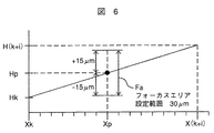
図6を用いて、本発明の焦点位置(高さ方向)の補間の一実施例を説明する。図6は、本発明により高さ方向の内挿補間(2点間の内挿)を行う場合の補間値を求める実施例を説明するための図である。
先ず、間引いて測定した測定点のX座標をXk、及びX(k+i)とし、それらの位置で測定した測定点の高さ方向の座標をHk、及びH(k+i)とする。
そして、全数測定時の任意測定点(間引かれた任意の測定点)のX座標をXpとし、その位置の測定点での高さ方向の座標(フォーカス移動位置)をHpを次式により求める。
Hp=((H(k+i)−Hk)×(Xp−Xk)÷(X(k+i)−Xk)+Hk
上記のようにして算出した高さ方向の座標Hpに対し、±15μ[m]のフォーカスエリアを設定することにより1点のフォーカス時間が1.5[s]から1.0[s]に短縮できる。
An embodiment of the interpolation of the focal position (height direction) according to the present invention will be described with reference to FIG. FIG. 6 is a diagram for explaining an embodiment for obtaining an interpolation value when performing interpolation in the height direction (interpolation between two points) according to the present invention.
First, let Xk and X (k + i) be the X coordinates of the measurement points measured by thinning out, and let Hk and H (k + i) be the coordinates in the height direction of the measurement points measured at those positions.
Then, the X coordinate of an arbitrary measurement point (arbitrary arbitrary measurement point) at the time of total measurement is Xp, and the height direction coordinate (focus movement position) at the measurement point at that position is obtained by the following equation. .
Hp = ((H (k + i) −Hk) × (Xp−Xk) ÷ (X (k + i) −Xk) + Hk
The focus time for one point is reduced from 1.5 [s] to 1.0 [s] by setting a focus area of ± 15 μ [m] for the coordinate Hp in the height direction calculated as described above. it can.
従って、図5の基板12の実施例では、トータルのフォーカス時間Ftは、135[s]秒から94.5[s]になる。測定時間Mtも450[s]から409.5[s]となり、40.5[s]短縮される。即ち、全測定位置数(測定点数)が90で、間引いた測定点数が81、フォーカス測定の測定点数が9点であるから、
Ft=フォーカス測定時間×フォーカス測定点数+フォーカス算出時間×フォーカス測定を間引いた測定点数
=1.5[s]×9[点]+1.0[s]×81
=94.5[s]
Mt=1点あたりの測定時間×フォーカス測定点数+補間の場合の測定時間×フォーカス測定を間引いた測定点数
=5[s]×9[点]+(5−0.5)[s]×81[点]
=409.5[s]
Accordingly, in the embodiment of the
Ft = focus measurement time × number of focus measurement points + focus calculation time × number of measurement points obtained by thinning out focus measurement = 1.5 [s] × 9 [points] +1.0 [s] × 81
= 94.5 [s]
Mt = measurement time per point × number of focus measurement points + measurement time in the case of interpolation × number of measurement points obtained by thinning focus measurement = 5 [s] × 9 [points] + (5-0.5) [s] × 81 [point]
= 409.5 [s]
上記実施例では、高さ位置を補間によって算出した場合のフォーカスエリアを小さく設定することによって、測定時間を短縮した。このフォーカスエリアをより小さく設定でき、光学ヘッドの焦点深度内まで絞り込むことができれば、補間した高さで測定可能となる、即ち合焦点動作を省略して測定可能となるので、更に測定時間を短縮できる。また、間引く数、即ち合焦点高さデータを取得する測定位置の数の全測定位置に対する割合が多ければ、フォーカスエリアを更に小さくできる。
なお、本発明の実施例では、一般的技術なので特に述べなかったが、合焦点の具体的な処理方法については、例えば、特開2003−98425号公報、特開2004−226994号公報、特開2007−140087号公報、等に開示されている。
In the above embodiment, the measurement time is shortened by setting the focus area small when the height position is calculated by interpolation. If this focus area can be set smaller and can be narrowed down to the depth of focus of the optical head, measurement can be performed at the interpolated height, that is, measurement can be performed without focusing operation, further reducing the measurement time. it can. If the ratio of the number of thinned out positions, that is, the number of measurement positions at which in-focus height data is acquired, to the total measurement positions is large, the focus area can be further reduced.
In the embodiment of the present invention, since it is a general technique, no particular mention was made, but specific processing methods for focusing are disclosed in, for example, Japanese Patent Application Laid-Open No. 2003-98425, Japanese Patent Application Laid-Open No. 2004-226994, and Japanese Patent Application Laid-Open No. 2004-226994. 2007-140087 and the like.
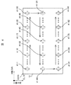
本発明の検査装置の一実施例の構成をによって説明する。図7は、本発明の検査装置の一実施例の構成を示すブロック図である。
図7に示すように、線幅測定装置700は、主に、カメラ、光学顕微鏡、及び対物レンズ721を含む光学ヘッド713、基板712を載置するステージ711、フレームグラバ( FG )724 、調光器723 、光源722、制御部746、モニタ725、X軸レール716、X軸ステージ715、Y軸ステージ714、ステージ駆動部726、及び、ステージ711を搭載する台座717で構成される。
また制御部746は、画像取込・表示部761、画像記憶部762、及び CPU( Central Processing Unit )763から成っている。更に、光学ヘッド713は、複数の倍率の対物レンズ721を図示しないレンズリボルバー機構を制御部746から制御することによって所望の倍率の対物レンズに切替制御し、光学ヘッド713のカメラが撮像する被測定対象物712の所望のエリアの拡大率を変更する。
なお、制御部746は、PC( Personal Computer )であっても良い。
また、光学ヘッドに用いるカメラには、固体撮像素子を使ったカメラ等があるが、特にそれに限ることは無く、画像処理に必要な画像を撮像することができるイメージセンサであれば良い。
A configuration of an embodiment of the inspection apparatus according to the present invention will be described. FIG. 7 is a block diagram showing the configuration of an embodiment of the inspection apparatus of the present invention.
As shown in FIG. 7, the line
The control unit 746 includes an image capture /
The control unit 746 may be a PC (Personal Computer).
The camera used for the optical head includes a camera using a solid-state imaging device, but is not particularly limited thereto, and may be any image sensor that can capture an image necessary for image processing.
また、ステージ711には、被検査対象物(基板712)が被写体として載置され、固定されている。台座717は、ステージ711を、Y方向(図面上の左右方向)とX方向(図面上の奥行き方向)に移動させる水平移動機構とZ方向(高さ方向)に移動させる高さ移動機構を備え、制御部746の制御によって基板712の所望の部分の画像を撮像することができる。
ステージ711は、例えば、基板712を固定するための吸着板であり、制御部746の制御によって、基板の搬入及び固定、並びに搬出を可能とする。X軸レール716、X軸ステージ15、Y軸ステージ14、及び光学ヘッド13は、制御部746に結合されたステージ駆動部726の制御によって、それぞれ、基板712のX方向、Y方向、Z方向に対して位置制御される。
On the
The
図7において、制御部746は、CPU763に登録された処理プログラムに従って、検査装置の各構成要素を制御する。
光源722からの光は、調光器723介して光学ヘッド713の光学顕微鏡に出力される。調光器723は、制御部746から制御されて光量を調整し、光学顕微鏡に光量の調整された光を出力する。例えば、調光器723は、画像のピーク値か平均値を画像レベルの最大値になるように、光量を調整する。そして、調光器723から入力された光は、光学顕微鏡を通して基板712に照射され、基板712は光を照射されたことによって反射光を出力し、出力された反射光は、光学ヘッド713の光学顕微鏡を通ってカメラに入射する。
光学ヘッド713のカメラは、入射された光を電気信号に変換して、変換した画像信号データをFG724に出力する。FG724は、画像データを制御部746に出力する画像入力ボードである。
In FIG. 7, the control unit 746 controls each component of the inspection apparatus according to the processing program registered in the
Light from the
The camera of the optical head 713 converts the incident light into an electrical signal and outputs the converted image signal data to the
上述のように、カメラが撮影した被検査対象物(基板712)の検査対象エリアの拡大画像は、画像信号として制御部746に供給され、制御部746内の画像取込・表示部761に入力される。この制御部746には、更に、画像記憶部762と、所定のプログラムが格納されたCPU763がある。
画像記憶部762は、画像、及び計算用のデータを記憶するのに使用され、システム全体の動作に必要な制御は、CPU763により実行される。
制御部746のプログラムは、この画像信号に画像処理を施すことにより、LCD基板のパターン線幅などを測定し、その結果をモニタ725に出力する。
As described above, an enlarged image of the inspection target area of the inspection target object (substrate 712) photographed by the camera is supplied to the control unit 746 as an image signal and input to the image capture /
The
The program of the control unit 746 measures the pattern line width of the LCD substrate by performing image processing on the image signal, and outputs the result to the
次に、図8と図7によって、上述のようなフォーカス測定時間の短縮を行う測定の一実施例の動作手順を説明する。図8は、本発明の検査装置の測定手順の一実施例を説明するためのフローチャートである。被測定対象物である基板712が検査装置700上のステージ711に戴置されて、基板712の測定が開始されると、制御部746の制御により、線幅測定装置700の各構成要素が駆動されることにより、ステップ801〜805の処理動作を実行する。
図8において、初期化ステップ801では、ステージ駆動部726の制御により、Xステージ715及びYステージ714が移動し、原点(0,0)に光学ヘッド713が移動する。かつ、駆動部726の制御により、光学ヘッド713は、高さ方向に移動可能な一番上まで移動する。
Next, referring to FIGS. 8 and 7, the operation procedure of one embodiment of the measurement for shortening the focus measurement time as described above will be described. FIG. 8 is a flowchart for explaining an embodiment of the measurement procedure of the inspection apparatus of the present invention. When the
In FIG. 8, in the
次に、間引き測定ステップ802では、全測定位置のうち、間引き測定することになっている測定位置にそれぞれについて、プログラムの実行順番通りに、測定位置まで、光学ヘッド713を移動させ、フォーカス値を定める。即ち、間引いた測定位置でのフォーカス設定では、フォーカスエリアを光学ヘッドが高さ方向に移動可能な全範囲内に上下に移動させ、適切な高さを定める。そして、図3によって説明したような画像処理によって、各測定位置でのパターンの位置ずれ量を算出する。更に、この測定位置でのパターン寸法の測定を行う。
なお、間引き測定する測定位置、及び間引き測定する測定位置は、被測定対象物の検査を実行するためのプログラムを作成するときに定められる。
次に、ステップ803では、間引き測定する測定位置がすべて測定を終了したか否かを判定し、終了していればステップ804に進み、終了していなければ、ステップ802に戻り処理を繰り返す。
Next, in a thinning
It should be noted that the measurement position at which thinning measurement is performed and the measurement position at which thinning measurement is performed are determined when a program for executing an inspection of an object to be measured is created.
Next, in
次に、全数測定ステップ804では、間引き測定ステップ802で測定しなかった測定位置について、プログラムの順番通りで、光学ヘッド713を水平(XY)方向に移動する。そして、間引き測定の時に取得した高さデータから補間をを行い、補間値プラスマイナス(±)15[μm]の範囲内で、フォーカスエリアを光学ヘッドが高さ方向に上下移動させ、適切な高さを定める。
次に、図3によって説明したような画像処理によって、各測定位置でのパターンの位置ずれ量を算出して水平方向の位置補正を行ってから、この測定位置でのパターン寸法の測定を行う。
次にステップ805では、全ての測定位置について測定が終了したか否かを判定し、終了していなければ、ステップ804を繰り返し、終了していれば、検査を終了する。
Next, in the total
Next, the amount of pattern displacement at each measurement position is calculated by image processing as described with reference to FIG. 3 to perform horizontal position correction, and then the pattern dimension is measured at this measurement position.
Next, in
なお、図8の実施例では、間引き測定ステップ802で、位置ずれ補正の他、画像処理のための画像を取得して寸法測定を行った。しかし、全数測定ステップ804で、画像処理によって寸法測定を行っても良い。
In the embodiment of FIG. 8, in the thinning
次に、上述の実施例では、全数測定では、フォーカス値の補間(高さ方向の位置の補間)を行った。しかし、水平(XY)方向の位置座標についても、同様の補間が可能である。以下、図9と図10を用いて、その実施例について説明する。図9は、本発明の水平位置座標の補間方法の一実施例を説明するための図である。また、図10は、以下において説明する測定位置Ph0での重み付けの計算について表形式で表した具体的な例を示す図である。
即ち、図9の実施例では、水平方向についても、図5で示した間引き測定した測定位置(測定点)41−1、41−15、41−30、41−31、41−45、41−60、41−61、41−75、41−90の座標を元に、他の測定位置(この実施例では、測定位置Ph0で代表している)のXY方向の補間を行いX座標とY座標の重み付けを行うことにより、熱変化に伴うズレ(ずれ)を補正するものである。
Next, in the above-described embodiment, focus value interpolation (interpolation of the position in the height direction) was performed in the total number measurement. However, the same interpolation is possible for the position coordinates in the horizontal (XY) direction. The embodiment will be described below with reference to FIGS. 9 and 10. FIG. 9 is a diagram for explaining an embodiment of the horizontal position coordinate interpolation method of the present invention. FIG. 10 is a diagram showing a specific example of the calculation of weights at the measurement position Ph0 described below in a tabular format.
That is, in the embodiment of FIG. 9, the measurement positions (measurement points) 41-1, 41-15, 41-30, 41-31, 41-45, 41− measured by the thinning shown in FIG. Based on the coordinates of 60, 41-61, 41-75, and 41-90, X and Y coordinates are interpolated in the XY directions of other measurement positions (represented by measurement position Ph0 in this embodiment). Is used to correct a deviation (displacement) due to a thermal change.
図9及び図10の重み付けの方法を、図11を参照しながら更に詳細に説明する。図11は、重み付けを具体的に実行して測定する手順を説明するためのフローチャートである。ここで、説明する処理は、例えば、図8で説明した全数測定ステップ804として実行される。
ステップ1101では、補正テーブルのうち、測定位置Ph0を囲む4点Ph1、Ph2、Ph3、Ph4を決定する。
即ち、間引き測定した測定位置41−1、41−15、41−30、41−31、41−45、41−60、41−61、41−75、41−90のX座標とY座標と、測定位置Ph0のX座標(Xp)とY座標(Yp)と比較する。
まず、Xpより小さくXpに一番近いX座標にある間引き測定した測定位置の点で、かつ、Ypより小さくYpに一番近いY座標にある間引き測定した測定位置の点を持つ間引き測定した測定位置をPh1(Xk,Yk)とする。
次に、Xpより小さくXpに一番近いX座標にある間引き測定した測定位置の点で、かつ、Ypより大きくYpに一番近いY座標にある間引き測定した測定位置の点を持つ間引き測定した測定位置をPh2(Xk,Yk+1)とする。
次に、Xpより大きくXpに一番近いX座標にある間引き測定した測定位置の点で、かつ、Ypより小さくYpに一番近いY座標にある間引き測定した測定位置の点を持つ間引き測定した測定位置をPh3(Xk+1,Yk)とする。
最後に、Xpより大きくXpに一番近いX座標にある間引き測定した測定位置の点で、かつ、Ypより大きくYpに一番近いY座標にある間引き測定した測定位置の点を持つ間引き測定した測定位置をPh4(Xk+1,Yk+1)とする。
なお、Ph1〜Ph4を求める順番は、本ステップでも他のステップでも特に問題ではない。これは、X座標とY座標でも同様である。
The weighting method of FIGS. 9 and 10 will be described in more detail with reference to FIG. FIG. 11 is a flowchart for explaining a procedure for measuring by specifically executing weighting. Here, the process to be described is executed, for example, as the total
In
That is, the X and Y coordinates of the measurement positions 41-1, 41-15, 41-30, 41-31, 41-45, 41-60, 41-61, 41-75, 41-90 measured by thinning, The X coordinate (Xp) and Y coordinate (Yp) of the measurement position Ph0 are compared.
First, measurement is performed by thinning measurement with a measurement position point measured by thinning at an X coordinate that is smaller than Xp and closest to Xp, and with a measurement position point that is smaller than Yp and closest to Yp at a Y coordinate. The position is Ph1 (Xk, Yk).
Next, thinning measurement was performed with a measurement position point measured by thinning at an X coordinate closest to Xp smaller than Xp and with a measurement position point measured at a Y coordinate larger than Yp and closest to Yp. The measurement position is Ph2 (Xk, Yk + 1).
Next, thinning measurement was performed with a measurement position point measured by thinning at an X coordinate closest to Xp that is larger than Xp and a measurement position point measured at a Y coordinate smaller than Yp and closest to Yp. The measurement position is Ph3 (Xk + 1, Yk).
Finally, thinning measurement is performed with a measurement position point measured by thinning at an X coordinate that is larger than Xp and closest to Xp, and has a measurement position point that is thinned and measured at a Y coordinate that is larger than Yp and closest to Yp. The measurement position is Ph4 (Xk + 1, Yk + 1).
The order of obtaining Ph1 to Ph4 is not particularly a problem in this step and other steps. The same applies to the X coordinate and the Y coordinate.
ステップ1102では、算出した間引き測定した測定位置4点Ph1〜Ph4それぞれとPh0間の距離R(R1〜R4)を算出する。
ステップ1103では、距離に反比例した加重平均を行う。このため、ステップ1102で算出した距離Rの逆数(1/R)をそれぞれ算出する。
ステップ1104では、:ステップ1103でそれぞれ算出した4点の距離の逆数(1/R)の総和SUM(1/R)を算出する。
なお、図10中の比率[%]は、距離に反比例した平均の重み付け(参考値)である。
ステップ1105では、上記4点Ph1〜Ph4それぞれに対して、X座標とY座標それぞれについて、補正値×(1/R)を算出する。
ステップ1106では、ステップ1105でそれぞれ算出した補正値×(1/R)を、X座標とY座標それぞれについて、総和を算出し、総和をステップ1104で算出したSUM(1/R)で割る。
In
In
In
Note that the ratio [%] in FIG. 10 is an average weight (reference value) inversely proportional to the distance.
In
In
ステップ1107では、ステップ1106で算出した補正値に基づいて、測定位置を補正する。
ステップ1108では、補正された測定位置に光学ヘッドを移動する。
ステップ1109では、画像を取得して画像処理によって線幅測定等の測定を行う。
そして、例えば、図8のステップ805に進む。
In
In
In
Then, for example, the process proceeds to step 805 in FIG.
なお、上記実施例では、測定位置の移動順序は、先ずX軸方向に略平行に移動し、その後Y軸方向に移動して、更にX軸方向に略平行に移動している。しかし、これに限らないことは勿論である。
また、上記実施例では、ガントリー形式のXY軸移動ステージを用いたが、この実施例に限るものではないことは言うまでもない。
また更に、上記実施例では、高さ補正では2点間の補間、位置補正では4点での補間で説明した。しかし、補間するデータの数は、これに限らず、いくつでも良いことは勿論のこと、線形補間の他、非線形補間でも良いことは自明である。
In the above embodiment, the movement order of the measurement positions is first moved substantially parallel to the X-axis direction, then moved to the Y-axis direction, and further moved substantially parallel to the X-axis direction. However, it is needless to say that the present invention is not limited to this.
In the above embodiment, the gantry-type XY axis moving stage is used, but it goes without saying that the present invention is not limited to this embodiment.
Furthermore, in the above-described embodiment, the description has been given of the interpolation between two points for height correction and the interpolation at four points for position correction. However, the number of data to be interpolated is not limited to this, and it is obvious that the number of data to be interpolated may be any number, as well as non-linear interpolation in addition to linear interpolation.
10:線幅測定装置、 11:ステージ、 12:基板、 13:光学ヘッド、 14:Y軸ステージ、 15:X軸ステージ、 16:X軸レール、 17:定盤、 21:レーザ干渉計、 22−1:LXAターゲットミラー、 22−2:LXBターゲットミラー、 23:LYターゲットミラー、 24−2,25:反射ミラー、 24−1,26:ハーフミラー、 27−1〜27−4,28−1,28−2,29:光路、 700:線幅測定装置、 711:ステージ、 712:基板、 713:光学ヘッド、 714:Y軸ステージ、 715:X軸ステージ、 716:X軸レール、 717:台座、 721:対物レンズ、 722:光源、 723:調光器、 724:フレームグラバ( FG )、 725:モニタ、 726:ステージ駆動部、 746:制御部、 761:画像取込・表示部、 762:画像記憶部、 763:CPU。 10: Line width measuring device, 11: Stage, 12: Substrate, 13: Optical head, 14: Y axis stage, 15: X axis stage, 16: X axis rail, 17: Surface plate, 21: Laser interferometer, 22 -1: LXA target mirror, 22-2: LXB target mirror, 23: LY target mirror, 24-2, 25: reflection mirror, 24-1, 26: half mirror, 27-1 to 27-4, 28-1 28-2, 29: Optical path, 700: Line width measuring device, 711: Stage, 712: Substrate, 713: Optical head, 714: Y-axis stage, 715: X-axis stage, 716: X-axis rail, 717: Pedestal , 721: objective lens, 722: light source, 723: dimmer, 724: frame grabber (FG), 725: monitor, 726: stage drive Part, 746: control unit, 761: image capture and display unit, 762: image storage unit, 763: CPU.
Claims (2)
高さ方向の位置を決定するための、第1のフォーカスエリアと該第1のフォーカスエリアより小さい範囲の第2のフォーカスエリアを設け、
測定位置毎に、第1のフォーカスエリアで合焦点するか第2のフォーカスエリアで合焦点するかを予め決めておき、
第1のフォーカスエリアで合焦点する測定位置について、測定位置毎に水平方向の位置と高さ方向の位置を測定し、
第1のフォーカスエリアで合焦点する測定位置の測定位置毎の水平方向の位置と高さ方向の位置から補間によって、第2のフォーカスエリアで合焦点する測定位置の、水平方向の位置と高さ方向の位置を補正し、
補正した位置において、第2のフォーカスエリアで合焦点する測定位置で線幅を測定することを特徴とする線幅測定装置の検査方法。 In the inspection method of the line width measuring device for measuring the line width of the pattern formed on the substrate,
Providing a first focus area for determining a position in the height direction and a second focus area in a range smaller than the first focus area;
For each measurement position, it is determined in advance whether to focus on the first focus area or the second focus area,
For the measurement position focused on in the first focus area, measure the horizontal position and height position for each measurement position,
The horizontal position and height of the measurement position focused on in the second focus area by interpolation from the horizontal position and height position for each measurement position of the measurement position focused on in the first focus area. Correct the position of the direction,
An inspection method for a line width measuring apparatus, characterized in that, at the corrected position, the line width is measured at a measurement position focused on in the second focus area.
高さ方向の位置を決定するための、第1のフォーカスエリアと該第1のフォーカスエリアより小さい範囲の第2のフォーカスエリアを設け、測定位置毎に、第1のフォーカスエリアで合焦点するか第2のフォーカスエリアで合焦点するかを予め決めておき、第1のフォーカスエリアで合焦点する測定位置について、測定位置毎に水平方向の位置と高さ方向の位置を測定し、第1のフォーカスエリアで合焦点する測定位置の測定位置毎の水平方向の位置と高さ方向の位置から補間によって、第2のフォーカスエリアで合焦点する測定位置の、水平方向の位置と高さ方向の位置を補正し、補正した位置において、第2のフォーカスエリアで合焦点する測定位置で前記被測定対象物上に形成されたパターンの線幅を測定することを特徴とする線幅測定装置。 A stage on which the object to be measured is placed and fixed, an optical head that captures an enlarged image of a predetermined position of the object to be measured on the stage, and a predetermined horizontal position of the object to be measured. And a moving mechanism for moving relative to the height position, a position measuring unit for measuring the horizontal position of the optical head with a laser interferometer, and a position for moving the height position of the optical head to the in-focus position A line width for measuring a dimension of a pattern formed on the object to be measured, including a focusing mechanism and an image processing unit that performs image processing on an image captured by the optical head and controls a line width measuring device In the measurement apparatus, the image processing unit includes:
Whether a first focus area for determining a position in the height direction and a second focus area in a range smaller than the first focus area are provided, and whether or not the first focus area is focused at each measurement position. Whether to focus in the second focus area is determined in advance, and for the measurement position to be focused in the first focus area, the horizontal position and the height direction position are measured for each measurement position, and the first focus area is measured. The horizontal position and height position of the measurement position focused in the second focus area by interpolation from the horizontal position and height position for each measurement position of the measurement position focused in the focus area It corrects, in the correction position, measuring the line width and measuring the line width of the pattern formed on said object to be measured at the measurement position of the focal point at the second focus area Apparatus.
Priority Applications (3)
| Application Number | Priority Date | Filing Date | Title |
|---|---|---|---|
| JP2007242361A JP5096852B2 (en) | 2007-09-19 | 2007-09-19 | Line width measuring apparatus and inspection method of line width measuring apparatus |
| KR1020107003227A KR101067996B1 (en) | 2007-09-19 | 2008-03-07 | Inspection method of line width measuring device |
| PCT/JP2008/054163 WO2009037875A1 (en) | 2007-09-19 | 2008-03-07 | Method for inspecting line width measuring apparatus |
Applications Claiming Priority (1)
| Application Number | Priority Date | Filing Date | Title |
|---|---|---|---|
| JP2007242361A JP5096852B2 (en) | 2007-09-19 | 2007-09-19 | Line width measuring apparatus and inspection method of line width measuring apparatus |
Publications (3)
| Publication Number | Publication Date |
|---|---|
| JP2009074849A JP2009074849A (en) | 2009-04-09 |
| JP2009074849A5 JP2009074849A5 (en) | 2010-10-21 |
| JP5096852B2 true JP5096852B2 (en) | 2012-12-12 |
Family
ID=40467701
Family Applications (1)
| Application Number | Title | Priority Date | Filing Date |
|---|---|---|---|
| JP2007242361A Active JP5096852B2 (en) | 2007-09-19 | 2007-09-19 | Line width measuring apparatus and inspection method of line width measuring apparatus |
Country Status (3)
| Country | Link |
|---|---|
| JP (1) | JP5096852B2 (en) |
| KR (1) | KR101067996B1 (en) |
| WO (1) | WO2009037875A1 (en) |
Families Citing this family (5)
| Publication number | Priority date | Publication date | Assignee | Title |
|---|---|---|---|---|
| WO2012111603A1 (en) * | 2011-02-17 | 2012-08-23 | シャープ株式会社 | Line width measurement device |
| US9080865B2 (en) | 2012-12-27 | 2015-07-14 | Shenzhen China Star Optoelectronics Technology Co., Ltd | Orthogonality compensation method for length measurement device and length measurement device using same |
| CN103075970B (en) * | 2012-12-27 | 2015-07-01 | 深圳市华星光电技术有限公司 | Method of compensating orthogonal degree of length measuring device and length measuring device using the same |
| US9110039B2 (en) * | 2013-07-25 | 2015-08-18 | Kla-Tencor Corporation | Auto-focus system and methods for die-to-die inspection |
| CN103837085B (en) * | 2014-03-07 | 2016-07-06 | 哈尔滨工业大学 | The displacement of targets device for measuring vector quantity demarcated based on laser tracker pointwise and method |
Family Cites Families (5)
| Publication number | Priority date | Publication date | Assignee | Title |
|---|---|---|---|---|
| JP2002228411A (en) * | 2001-02-05 | 2002-08-14 | Hitachi Kokusai Electric Inc | Two-dimensional measuring apparatus |
| JP2004294358A (en) * | 2003-03-28 | 2004-10-21 | Hitachi High-Technologies Corp | Method and apparatus for inspecting defect |
| JP4119788B2 (en) * | 2003-05-23 | 2008-07-16 | 三菱重工業株式会社 | Shape measurement system and method |
| JP4485931B2 (en) * | 2004-12-20 | 2010-06-23 | 株式会社ディスコ | Focus adjustment method |
| JP2007121981A (en) * | 2005-09-30 | 2007-05-17 | Matsushita Electric Ind Co Ltd | Substrate test method |
-
2007
- 2007-09-19 JP JP2007242361A patent/JP5096852B2/en active Active
-
2008
- 2008-03-07 KR KR1020107003227A patent/KR101067996B1/en active IP Right Grant
- 2008-03-07 WO PCT/JP2008/054163 patent/WO2009037875A1/en active Application Filing
Also Published As
| Publication number | Publication date |
|---|---|
| KR20100034038A (en) | 2010-03-31 |
| JP2009074849A (en) | 2009-04-09 |
| KR101067996B1 (en) | 2011-09-26 |
| WO2009037875A1 (en) | 2009-03-26 |
Similar Documents
| Publication | Publication Date | Title |
|---|---|---|
| JP5331828B2 (en) | Charged particle beam equipment | |
| JP4903627B2 (en) | Surface mounter and camera position correction method thereof | |
| US10310010B2 (en) | Probe apparatus and probe method | |
| JP5096852B2 (en) | Line width measuring apparatus and inspection method of line width measuring apparatus | |
| US20060018560A1 (en) | Exposure device and exposure method | |
| JP2019066471A (en) | Inspection method and inspection device | |
| JP2007108037A (en) | Position measurement method, distance measurement method and position measurement device | |
| JP2023541838A (en) | Exposure control in photolithographic direct exposure processes for circuit board or circuit manufacturing | |
| JP6650629B1 (en) | Laser processing device and imaging device | |
| JP2011033507A (en) | Three-dimensional measuring apparatus | |
| JP2007218846A (en) | Dimensional measurement method, imaging device, controller, and dimensional measuring device | |
| KR102078079B1 (en) | Exposure apparatus, exposure method, and article manufacturing method | |
| JP2003294419A (en) | Measuring instrument for infinitesimal dimension | |
| TWI759621B (en) | Drawing apparatus and drawing method | |
| US9594230B2 (en) | On-axis focus sensor and method | |
| JP4384446B2 (en) | Autofocus method and apparatus | |
| KR20070049061A (en) | Substrate measuring apparatus | |
| JP2008209295A (en) | Device for measuring size | |
| JP5319063B2 (en) | Line width measuring device | |
| JP2004184411A (en) | Position recognition method | |
| JP2001313241A (en) | Aligner and aligning method | |
| JP2007292683A (en) | Sample measuring apparatus and sample stage adjusting method of sample measuring apparatus | |
| JP2003152037A (en) | Method and apparatus for inspecting wafer as well as inspecting infrared imaging unit | |
| JP4895356B2 (en) | Line width measuring device | |
| KR100672166B1 (en) | Line width measuring method |
Legal Events
| Date | Code | Title | Description |
|---|---|---|---|
| A521 | Request for written amendment filed |
Free format text: JAPANESE INTERMEDIATE CODE: A523 Effective date: 20100908 |
|
| A621 | Written request for application examination |
Free format text: JAPANESE INTERMEDIATE CODE: A621 Effective date: 20100908 |
|
| A131 | Notification of reasons for refusal |
Free format text: JAPANESE INTERMEDIATE CODE: A131 Effective date: 20120529 |
|
| A521 | Request for written amendment filed |
Free format text: JAPANESE INTERMEDIATE CODE: A523 Effective date: 20120725 |
|
| TRDD | Decision of grant or rejection written | ||
| A01 | Written decision to grant a patent or to grant a registration (utility model) |
Free format text: JAPANESE INTERMEDIATE CODE: A01 Effective date: 20120904 |
|
| A01 | Written decision to grant a patent or to grant a registration (utility model) |
Free format text: JAPANESE INTERMEDIATE CODE: A01 |
|
| A61 | First payment of annual fees (during grant procedure) |
Free format text: JAPANESE INTERMEDIATE CODE: A61 Effective date: 20120921 |
|
| R150 | Certificate of patent or registration of utility model |
Ref document number: 5096852 Country of ref document: JP Free format text: JAPANESE INTERMEDIATE CODE: R150 Free format text: JAPANESE INTERMEDIATE CODE: R150 |
|
| FPAY | Renewal fee payment (event date is renewal date of database) |
Free format text: PAYMENT UNTIL: 20150928 Year of fee payment: 3 |
|
| S111 | Request for change of ownership or part of ownership |
Free format text: JAPANESE INTERMEDIATE CODE: R313113 |
|
| R350 | Written notification of registration of transfer |
Free format text: JAPANESE INTERMEDIATE CODE: R350 |
|
| RD03 | Notification of appointment of power of attorney |
Free format text: JAPANESE INTERMEDIATE CODE: R3D03 |
|
| R250 | Receipt of annual fees |
Free format text: JAPANESE INTERMEDIATE CODE: R250 |
|
| R250 | Receipt of annual fees |
Free format text: JAPANESE INTERMEDIATE CODE: R250 |
|
| R250 | Receipt of annual fees |
Free format text: JAPANESE INTERMEDIATE CODE: R250 |
|
| R250 | Receipt of annual fees |
Free format text: JAPANESE INTERMEDIATE CODE: R250 |