JP5094501B2 - Cooker - Google Patents

Cooker Download PDF

Info

Publication number
JP5094501B2
JP5094501B2 JP2008086031A JP2008086031A JP5094501B2 JP 5094501 B2 JP5094501 B2 JP 5094501B2 JP 2008086031 A JP2008086031 A JP 2008086031A JP 2008086031 A JP2008086031 A JP 2008086031A JP 5094501 B2 JP5094501 B2 JP 5094501B2
Authority
JP
Japan
Prior art keywords
heating
unit
person
heated
human sensor
Prior art date
Legal status (The legal status is an assumption and is not a legal conclusion. Google has not performed a legal analysis and makes no representation as to the accuracy of the status listed.)
Active
Application number
JP2008086031A
Other languages
Japanese (ja)
Other versions
JP2009238684A (en
Inventor
智輝 束田
浩 重原
健一郎 西
英一 原田
大輔 伊藤
芳紀 若月
幸男 川田
浩志郎 榊原
加津典 関根
盟一 荻島
茂俊 一法師
孝 小川
義博 小佐野
Current Assignee (The listed assignees may be inaccurate. Google has not performed a legal analysis and makes no representation or warranty as to the accuracy of the list.)
Mitsubishi Electric Home Appliance Co Ltd
Mitsubishi Electric Corp
Original Assignee
Mitsubishi Electric Home Appliance Co Ltd
Mitsubishi Electric Corp
Priority date (The priority date is an assumption and is not a legal conclusion. Google has not performed a legal analysis and makes no representation as to the accuracy of the date listed.)
Filing date
Publication date
Application filed by Mitsubishi Electric Home Appliance Co Ltd, Mitsubishi Electric Corp filed Critical Mitsubishi Electric Home Appliance Co Ltd
Priority to JP2008086031A priority Critical patent/JP5094501B2/en
Publication of JP2009238684A publication Critical patent/JP2009238684A/en
Application granted granted Critical
Publication of JP5094501B2 publication Critical patent/JP5094501B2/en
Active legal-status Critical Current
Anticipated expiration legal-status Critical

Links

Images

Description

この発明は、加熱制御に関する操作の入力を行う操作部を有する加熱調理器に関するものである。   The present invention relates to a cooking device having an operation unit that inputs an operation related to heating control.

従来の加熱調理器においては、例えば「…操作手段の近傍に人の操作部の存在有無情報を前記加熱制御手段に伝達する第一の人体検知手段と、前記操作手段を操作する人が居る方向に人が居るか居ないかの存在有無情報を前記加熱制御手段に伝達する第二の人体検知手段とを備えた調理装置。」が提案されている(例えば、特許文献1参照)。   In a conventional cooking device, for example, “... a direction in which there is a first human body detecting means for transmitting presence / absence information of a human operation unit to the heating control means in the vicinity of the operating means and a person operating the operating means. A cooking apparatus provided with second human body detection means for transmitting presence / absence information on whether or not a person is present to the heating control means has been proposed (for example, see Patent Document 1).

また、例えば「前記検出手段が天板上において異物あるいは小動物等の操作者以外のものを検出したときに、前記制御部が誤動作するのを防止する誤動作防止手段を設けた」ものが提案されている(例えば、特許文献2参照)。   In addition, for example, "providing a malfunction prevention means for preventing the control unit from malfunctioning when the detection means detects an object other than an operator such as a foreign object or a small animal on the top board" has been proposed. (For example, refer to Patent Document 2).

特開2006−78079号公報(請求項1)JP 2006-78079 A (Claim 1) 特開2004−360926号公報(請求項10)JP 2004-360926 A (Claim 10)

従来の加熱調理器は、幼児や小動物(ペット)などによる誤操作、不用意に操作ボタン上に物が置かれた場合などの誤操作を防止するため、入力操作を受け付けない操作ロック機能を設定し、特定のキーを長押ししたり、電源と異なるキーを押してから電源を押すような複数のキー操作を行うことにより操作ロックを解除した後、加熱制御などの操作を行うことにより安全性の向上を図っている。しかしながら、操作を開始する際には、毎回特定キーの長押しや複数のキー操作を行う必要があり、スムースな調理動作や手順を妨げてしまい操作性が悪い、という問題点があった。   The conventional cooking device has an operation lock function that does not accept input operations in order to prevent accidental operations such as infants and small animals (pets), etc., and inadvertently placing objects on the operation buttons. After unlocking the operation by pressing a specific key for a long time, or by pressing a key different from the power supply and then pressing the power supply, the operation lock is released, and then the safety is improved by performing operations such as heating control. I am trying. However, when starting the operation, it is necessary to perform a long press of a specific key or a plurality of key operations every time, which hinders a smooth cooking operation and a procedure, resulting in poor operability.

この発明は、上記のような課題を解決するためになされたもので、誤操作を防止して安全性の向上を図ることができ、操作ロック解除の操作性を向上させることができる加熱調理器を得ることを目的とする。   The present invention has been made to solve the above-described problems. A heating cooker that can prevent erroneous operation and improve safety, and can improve the operability of operation lock release. The purpose is to obtain.

この発明に係る加熱調理器は、被加熱物を加熱する加熱部と、加熱制御に関する操作の入力を行う操作部と、前記操作部からの入力に基づく制御を行わないロック状態、又は前記ロック状態を解除して前記操作部からの入力に基づく制御を行う解除状態の何れかを選択し、選択した当該状態に応じて前記加熱部を制御する制御部と、検知領域における人の存否を検知する人感センサとを備え、前記人感センサは、少なくとも本体前面側の水平方向における人の存否を検知する1又は複数の第1の人感センサと、少なくとも前記第1の人感センサの検知領域より上方の検知領域における前記人の存否を検知する1又は複数の第2の人感センサとを有し、前記制御部は、前記第1の人感センサが人の存在を検知した時と、前記第2の人感センサが前記人の存在を検知した時との時間差が、所定時間差以下のとき、前記解除状態を選択するものである。
The cooking device according to the present invention includes a heating unit that heats an object to be heated, an operation unit that inputs an operation related to heating control, a locked state in which control based on an input from the operation unit is not performed, or the locked state The control unit that controls the heating unit according to the selected state and the presence / absence of a person in the detection region are detected. A human sensor, and the human sensor detects at least one first human sensor that detects the presence or absence of a person in the horizontal direction on the front side of the main body, and a detection area of at least the first human sensor. One or a plurality of second human sensors for detecting the presence or absence of the person in the upper detection area, the control unit, when the first human sensor detects the presence of a person, The second human sensor Time difference between when it detects the presence of the serial people, when more than a predetermined time difference, and selects the released state.

この発明の加熱調理器は、人感センサの検知結果に基づいて、ロック状態又は解除状態を選択し、選択した当該状態に応じて加熱部を制御することにより、誤操作を防止して安全性の向上を図ることができ、操作ロック解除の操作性を向上させることができる。   The heating cooker according to the present invention selects the locked state or the released state based on the detection result of the human sensor and controls the heating unit according to the selected state, thereby preventing erroneous operation and ensuring safety. Improvement can be aimed at and the operativity of operation lock release can be improved.

実施の形態1.
図1はこの発明の実施の形態1に係る加熱調理器の上部及び前面外形図、図2はこの発明の実施の形態1に係る加熱調理器の内部構造を示す図である。図1及び図2において、本実施の形態1に係る加熱調理器は、誘導加熱調理器本体1の上面に耐熱性のガラスと金属の枠体で構成する天板2が取り付けられるように構成されている。天板2の表面には、誘導加熱調理器本体1内の加熱コイル3が配設される位置に加熱領域を示す目的で円形の表示(以下、加熱口4a〜4cという。)が裏面から印刷されている。天板2の耐熱性ガラスは透明な素材であるが、加熱口以外の部分についても誘導加熱調理器本体1内部が露見しないよう或いは外観の質感向上のためこの天板2は裏面より印刷若しくは塗装されている。加熱口4a〜4cについては、本実施の形態1では加熱口4a及び4bは比較的加熱出力を大きく設定した加熱口であり、加熱口4cは前述の2つの加熱口に対して比較的加熱出力を小さく設定した加熱口である。
Embodiment 1 FIG.
FIG. 1 is an upper and front external view of a heating cooker according to Embodiment 1 of the present invention, and FIG. 2 is a view showing an internal structure of the heating cooker according to Embodiment 1 of the present invention. 1 and 2, the heating cooker according to the first embodiment is configured such that a top plate 2 composed of a heat-resistant glass and a metal frame is attached to the upper surface of the induction heating cooker body 1. ing. A circular display (hereinafter referred to as heating ports 4a to 4c) is printed from the back surface of the top plate 2 for the purpose of showing a heating region at a position where the heating coil 3 in the induction heating cooker body 1 is disposed. Has been. The heat-resistant glass of the top plate 2 is a transparent material, but the top plate 2 is printed or painted from the back side so that the inside of the induction heating cooker main body 1 is not exposed in the portion other than the heating opening or the appearance is improved. Has been. As for the heating ports 4a to 4c, in the first embodiment, the heating ports 4a and 4b are heating ports with a relatively large heating output, and the heating port 4c has a relatively high heating output with respect to the above-described two heating ports. Is a heating port set to be small.

誘導加熱調理器本体1の上部手前側には、入力操作や設定火力の状態などの情報を表示する表示部5(5a〜5c)と、加熱制御に関する操作の入力を行う操作部6(6a〜6c)とが各加熱口4ごとにそれぞれ設けられている。そして、天板2の表示部5と略同じ範囲は、印刷若しくは塗装が成されない構成で透明性を有しており、表示部5に表示される表示内容が天板2の表面より視認可能になっている。操作部6は、透明性の導電性フィルムなどの電極で構成したタッチスイッチであり、使用者の指などが電極の配置位置に接触する際における静電容量の変化により入力操作を検知する。表示部5は、液晶パネルなどで構成し、操作部6の下に配置される。尚、操作部6は、タッチスイッチに限らず、例えばメンブレンシートを用いた接点ボタンでも良い。この場合、操作部6は天板2の上面に配置する。   On the upper front side of the induction heating cooker main body 1, a display unit 5 (5 a to 5 c) that displays information such as an input operation and a setting thermal power state, and an operation unit 6 (6 a to 6 a that inputs operations related to heating control). 6c) is provided for each heating port 4. And the range substantially the same as the display part 5 of the top plate 2 has transparency with the structure which is not printed or painted, and the display content displayed on the display part 5 is visible from the surface of the top plate 2 It has become. The operation unit 6 is a touch switch composed of an electrode such as a transparent conductive film, and detects an input operation based on a change in capacitance when a user's finger or the like comes into contact with the electrode arrangement position. The display unit 5 is composed of a liquid crystal panel or the like, and is disposed under the operation unit 6. The operation unit 6 is not limited to a touch switch, and may be a contact button using a membrane sheet, for example. In this case, the operation unit 6 is disposed on the top surface of the top plate 2.

誘導加熱調理器本体1の天板2の下部には、被加熱物を加熱する加熱部である加熱コイル3が配置され、加熱コイル3へ供給する高周波電流を生成するインバータ7と、後述するロック状態又は解除状態に応じて、操作部6から入力された操作に基づいて、インバータ7を制御して火力制御を行ったり、表示部5への各種表示指令を行う制御部10が配置される構成となっている。   A heating coil 3 that is a heating unit that heats an object to be heated is disposed below the top plate 2 of the induction heating cooker body 1, an inverter 7 that generates a high-frequency current to be supplied to the heating coil 3, and a lock described later. A configuration in which a control unit 10 that controls the inverter 7 to control the thermal power based on the operation input from the operation unit 6 according to the state or the released state or performs various display commands to the display unit 5 is arranged. It has become.

さらに、誘導加熱調理器本体1の前面側には、誘導加熱調理器本体1の前面側の水平方向を検知領域とし、当該検知領域における人の存否を検知する第1の人感センサ20が複数(例えば4つ)設けられる。また、誘導加熱調理器本体1の上部手前側には、第1の人感センサ20の検知領域より上方の検知領域における人の存否を検知する第2の人感センサ21を複数(例えば4つ)設けられる。尚、第2の人感センサ21は、その設置角度を可動自在とすることにより、検知領域を可変可能である。   Further, on the front side of the induction heating cooker body 1, a plurality of first human sensors 20 that detect the presence or absence of a person in the detection area with the horizontal direction on the front side of the induction heating cooker body 1 as a detection area. (For example, four) are provided. In addition, on the upper front side of the induction heating cooker body 1, a plurality of (for example, four) second human sensors 21 that detect the presence or absence of a person in a detection area above the detection area of the first human sensor 20. ) Is provided. Note that the detection area of the second human sensor 21 can be varied by making the installation angle movable.

尚、第1の人感センサ20及び第2の人感センサ21の設置場所は、これに限るものではなく、上記検知領域を検知するものであれば任意の場所に設置することができる。   In addition, the installation location of the 1st human sensor 20 and the 2nd human sensor 21 is not restricted to this, It can install in arbitrary places, if the said detection area is detected.

第1の人感センサ20及び第2の人感センサ21は、例えば発光素子と受光素子とを有するフォトセンサからなり、発光素子からの光が検知物(人)に当たり、反射した光を受光素子で受けて検知するものである。尚、フォトセンサに限らず、検知領域における人の存否を検知するものであれば良く、例えば超音波方式、カメラ画像方式、温度検知方式など任意の検知方式を用いることができる。   The first human sensor 20 and the second human sensor 21 are composed of, for example, a photosensor having a light emitting element and a light receiving element. Light from the light emitting element hits a detection object (person) and the reflected light is received by the light receiving element. It will be received and detected. Note that the detection method is not limited to a photosensor, and any detection method such as an ultrasonic method, a camera image method, or a temperature detection method can be used.

尚、第1の人感センサ20及び第2の人感センサ21は、誘導加熱調理器本体1の大きさ・形状、又は各人感センサの検知領域の範囲に応じて、任意の個数を配置するようにしても良い。   In addition, the 1st human sensor 20 and the 2nd human sensor 21 arrange | position arbitrary numbers according to the magnitude | size and shape of the induction heating cooker main body 1, or the range of the detection area of each human sensor. You may make it do.

図3はこの発明の実施の形態1に係る人感センサの検知状態を示す図であり、図3(a)は誘導加熱調理器本体1の前面側に操作可能者が存在している場合の検知状態を示す図、図3(b)は誘導加熱調理器本体1の前面側に幼児が存在している場合の検知状態を示す図である。
図3に示すように、誘導加熱調理器本体1は、例えばキッチンカウンター等により、所定の高さに設置される。このような設置状態において、誘導加熱調理器本体1の前面側に所定以上の身長を有する人(以下「操作可能者」ともいう。)が存在すると、第1の人感センサ20及び第2の人感センサ21の何れの検知領域においても人の存在を検知することとなる。一方、例えば幼児など所定の身長に満たない人が、誘導加熱調理器本体1の前面側に存在する場合、第1の人感センサ20は人の存在を検知するが、第2の人感センサ21は人の存在を検知しないこととなる。さらに、例えばペットなどの小動物(図示せず)が、誘導加熱調理器本体1の上部に乗った場合、第2の人感センサ21は検知するが、第1の人感センサ20は検知することはない。このように、誘導加熱調理器本体1が設置される高さに応じて、第2の人感センサ21の検知領域を、所定以上の身長を有する人を検知するように設定することにより、操作可能者の存否を判断することが可能となる。
FIG. 3 is a diagram illustrating a detection state of the human sensor according to the first embodiment of the present invention, and FIG. 3 (a) is a case where an operator is present on the front side of the induction heating cooker body 1. The figure which shows a detection state, FIG.3 (b) is a figure which shows a detection state in case the infant exists in the front side of the induction heating cooking appliance main body 1. FIG.
As shown in FIG. 3, the induction heating cooker body 1 is installed at a predetermined height by, for example, a kitchen counter. In such an installed state, if there is a person (hereinafter also referred to as “operable person”) having a height of a predetermined height or more on the front side of the induction heating cooker body 1, the first human sensor 20 and the second human sensor 20 are provided. The presence of a person is detected in any detection region of the human sensor 21. On the other hand, when a person who is less than a predetermined height, such as an infant, is present on the front side of the induction heating cooker body 1, the first human sensor 20 detects the presence of a person, but the second human sensor 21 does not detect the presence of a person. Further, for example, when a small animal (not shown) such as a pet rides on the upper portion of the induction heating cooker body 1, the second human sensor 21 detects the first human sensor 20 but detects it. There is no. Thus, by setting the detection area of the second human sensor 21 so as to detect a person having a height of a predetermined level or more according to the height at which the induction heating cooker main body 1 is installed, the operation is performed. It becomes possible to determine the existence of a possible person.

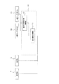
図4はこの発明の実施の形態1に係る加熱調理器のブロック構成図である。図4に示すように、制御部10は、表示操作制御部11と、操作可能者有無判断部12とから構成されている。操作可能者有無判断部12は、第1の人感センサ20及び第2の人感センサ21の検知結果が入力され、後述する動作により、第1の人感センサ20及び第2の人感センサ21の検知結果に基づいて、操作可能者の存否を判断する。表示操作制御部11は、表示部5及び操作部6と接続され、操作可能者有無判断部12の判断結果に従い、後述する動作によりロック状態又は解除状態を選択し、当該状態に応じて、操作部6から入力された各種の操作に基づき、インバータ7への加熱制御や制御内容に基づく各種表示指令を表示部5に行う。   FIG. 4 is a block configuration diagram of the heating cooker according to Embodiment 1 of the present invention. As shown in FIG. 4, the control unit 10 includes a display operation control unit 11 and an operable person presence / absence determination unit 12. The operable person presence / absence determination unit 12 receives the detection results of the first human sensor 20 and the second human sensor 21, and the first human sensor 20 and the second human sensor are operated by an operation described later. Based on the detection result 21, the presence / absence of an operable person is determined. The display operation control unit 11 is connected to the display unit 5 and the operation unit 6, selects a locked state or a released state by an operation described later according to the determination result of the operable person presence / absence determination unit 12, and operates according to the state. Based on various operations input from the unit 6, the display unit 5 is subjected to various display commands based on heating control to the inverter 7 and control contents.

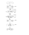
図5はこの発明の実施の形態1に係る解除動作を示すフローチャート、図6はこの発明の実施の形態1に係る表示部の状態遷移を示す図である。以下、本実施の形態1におけるロック解除動作について、図5に基づき図6を参照しながら説明する。
まず、誘導加熱調理器本体1の主電源(図示せず)が投入されると、各構成部は動作を開始する。主電源投入直後、又は手動操作や後述するロック設定動作によりロック状態に設定した場合、制御部10はロック状態を選択しており、操作部6からの入力に基づく制御を行わない(S101)。このとき制御部10の表示操作制御部11は、ロック状態を識別する表示として、操作ボタンに関する表示を表示部5に表示させない表示指令を行う。例えば、図6(a)に示すように、主電源投入直後は表示部5に何らの表示を行わない。尚、例えば煮込み中など加熱制御中である場合は、火力情報などを表示するようにしても良い。
FIG. 5 is a flowchart showing the release operation according to Embodiment 1 of the present invention, and FIG. 6 is a diagram showing state transition of the display unit according to Embodiment 1 of the present invention. Hereinafter, the unlocking operation in the first embodiment will be described with reference to FIG. 6 based on FIG.
First, when a main power source (not shown) of the induction heating cooker body 1 is turned on, each component starts its operation. Immediately after the main power is turned on or when the lock state is set by manual operation or a lock setting operation described later, the control unit 10 selects the lock state and does not perform control based on the input from the operation unit 6 (S101). At this time, the display operation control unit 11 of the control unit 10 issues a display command for not displaying the display relating to the operation button on the display unit 5 as a display for identifying the lock state. For example, as shown in FIG. 6A, no display is performed on the display unit 5 immediately after the main power is turned on. Note that, for example, when heating control is being performed such as during cooking, thermal power information or the like may be displayed.

次に、制御部10の操作可能者有無判断部12は、第1の人感センサ20及び第2の人感センサ21の検知結果に基づき、誘導加熱調理器本体1の前面側に操作可能者が存在するか否かを判断する(S102,S103)。この判断は、例えば第1の人感センサ20が所定時間以上(例えば数秒)人の存在を検知し、さらに、この人の存在を検知した第1の人感センサ20の検知領域の上方を検知領域とする第2の人感センサ21も所定時間以上(例えば数秒)人の存在を検知したとき、操作可能者が存在すると判断する。   Next, the operable person presence / absence determining unit 12 of the control unit 10 is operated on the front side of the induction heating cooker body 1 based on the detection results of the first human sensor 20 and the second human sensor 21. Is determined (S102, S103). This determination is made, for example, when the first human sensor 20 detects the presence of a person for a predetermined time or longer (for example, several seconds) and further detects the upper part of the detection area of the first human sensor 20 that has detected the presence of this person. The second human sensor 21 as a region also determines that there is an operable person when the presence of a person is detected for a predetermined time or longer (for example, several seconds).

制御部10は、操作可能者が存在すると判断したとき、ロック状態を解除して解除状態を選択し、操作部6からの入力に基づく制御を行う(S104)。そして表示操作制御部11は、解除状態を識別する表示として、操作可能な操作ボタンを表示部5に表示させる(S105)。これによりタッチスイッチが操作可能である旨を、操作可能者は認識することができる。例えば、図6(b)に示すように、主電源投入直後に操作可能者を検知した場合は、電源ボタン51を表示させる。尚、例えば煮込み中など加熱制御中である場合は、火力調整ボタンや電源オフボタンなどを表示するようにしても良い。
以降、操作部6からの操作に基づき、通常の加熱制御などが行われる。
When determining that there is an operable person, the control unit 10 releases the lock state, selects the release state, and performs control based on the input from the operation unit 6 (S104). And the display operation control part 11 displays the operation button which can be operated on the display part 5 as a display which identifies a cancellation | release state (S105). Accordingly, the operable person can recognize that the touch switch can be operated. For example, as shown in FIG. 6B, when an operable person is detected immediately after the main power is turned on, the power button 51 is displayed. For example, when heating control is being performed, such as during cooking, a thermal power adjustment button, a power-off button, or the like may be displayed.
Thereafter, normal heating control and the like are performed based on the operation from the operation unit 6.

尚、上記説明では、解除状態において操作ボタンを表示する場合を説明したが、これに限らず、例えば図7に示すように、操作ボタン表示52が、予め表示部5の上面又は天板2の裏面に印刷されている場合、解除状態を識別する表示として、操作可能な操作ボタンに対応する箇所を点灯・点滅表示するようにしても良い。また、例えば図8に示すように、操作部6としてLED付メンブレンシートなどの接点ボタンを用いる場合、解除状態を識別する表示として、操作可能な操作ボタンのLEDを点灯・点滅表示するようにしても良い。   In the above description, the operation button is displayed in the release state. However, the present invention is not limited to this. For example, as shown in FIG. When printed on the back side, as a display for identifying the release state, a portion corresponding to an operable operation button may be lit or blinked. For example, as shown in FIG. 8, when a contact button such as a membrane sheet with an LED is used as the operation unit 6, the LED of the operation button that can be operated is lit and blinked as a display for identifying the release state. Also good.

図9はこの発明の実施の形態1に係るロック動作を示すフローチャートである。次に、本実施の形態1におけるロック設定動作について、図9に基づき説明する。
制御部10は、上述した解除状態を選択したとき、ロック設定動作を開始する。操作可能者有無判断部12は、第1の人感センサ20及び第2の人感センサ21の検知結果に基づき、誘導加熱調理器本体1の前面側に操作可能者が存在するか否かを判断する(S201,S202)。この判断は、第1の人感センサ20、又はこれに対応する検知領域の第2の人感センサ21が人の存在を検知しないとき、操作可能者が存在しないと判断する。
FIG. 9 is a flowchart showing the locking operation according to the first embodiment of the present invention. Next, the lock setting operation in the first embodiment will be described with reference to FIG.
When the controller 10 selects the release state described above, the controller 10 starts a lock setting operation. The operable person presence / absence determination unit 12 determines whether there is an operable person on the front side of the induction heating cooker body 1 based on the detection results of the first human sensor 20 and the second human sensor 21. Judgment is made (S201, S202). This determination is made when there is no operable person when the first human sensor 20 or the second human sensor 21 in the corresponding detection region does not detect the presence of a person.

制御部10は、操作可能者が存在しないと判断したとき、ロック状態を選択し、操作部6からの入力に基づく制御を行わない(S203)。そして表示操作制御部11は、ロック状態を識別する表示として、操作ボタンなどの操作に係る表示を表示部5に表示させない(S204)。尚、例えば煮込み中など加熱制御中である場合は、火力情報などを表示するようにしても良い。
以降、上述したロック解除動作がなされるまでロック状態が保持されることとなる。
When determining that there is no person who can operate, the control unit 10 selects the locked state and does not perform control based on the input from the operation unit 6 (S203). And the display operation control part 11 does not display the display which concerns on operation, such as an operation button, on the display part 5 as a display which identifies a locked state (S204). Note that, for example, when heating control is being performed such as during cooking, thermal power information or the like may be displayed.
Thereafter, the locked state is maintained until the above-described unlocking operation is performed.

尚、上記説明では、人感センサによりロック状態に設定する動作について説明したが、これに限らず、例えば操作部6からの任意の操作により、ロック状態に設定するようにしても良い。   In the above description, the operation of setting the locked state by the human sensor has been described. However, the operation is not limited to this, and the locked state may be set by an arbitrary operation from the operation unit 6, for example.

以上のように本実施の形態においては、第1の人感センサ20及び第2の人感センサ21の検知結果に基づき、誘導加熱調理器本体1の前面側に操作可能者が存在するか否かを判断し、操作可能者が誘導加熱調理器本体1の前面側に存在するとき、解除状態とするので、ロック状態を解除するために特定のキーを長押ししたり、電源と異なるキーを押してから電源を押すような複数のキー操作を行う必要が無く、ロック解除の操作性を向上させることができる。   As described above, in the present embodiment, based on the detection results of the first human sensor 20 and the second human sensor 21, whether there is an operable person on the front side of the induction heating cooker body 1 or not. When the operator is present on the front side of the induction heating cooker body 1, the unlocked state is set, so that a specific key can be held down to release the locked state or a key different from the power source can be pressed. There is no need to perform a plurality of key operations such as pressing the power source after pressing, and the operability of unlocking can be improved.

また、例えば幼児など所定の身長に満たない人が誘導加熱調理器本体1の前面側に存在する場合、又は例えばペットなどの小動物が、誘導加熱調理器本体1の上部に乗った場合に、第1の人感センサ20又は第2の人感センサ21が人の存在を検知しても、ロック状態が解除されることがないので、例えば幼児や小動物などによる誤操作を防止して安全性の向上を図ることができる。   In addition, for example, when a person who is less than a predetermined height such as an infant is present on the front side of the induction heating cooker body 1 or when a small animal such as a pet rides on the top of the induction heating cooker body 1, Even if the first human sensor 20 or the second human sensor 21 detects the presence of a person, the locked state is not released. For example, an erroneous operation by an infant or a small animal is prevented, thereby improving safety. Can be achieved.

また、例えば操作可能な操作ボタンの表示の有無など、ロック状態と解除状態とを識別する表示をすることにより、操作可能者はロック状態又は解除状態の何れの状態であるかを認識することができ、操作性を向上させることができる。   In addition, the operator can recognize whether it is in the locked state or the released state by displaying, for example, whether or not an operable operation button is displayed, to identify the locked state and the released state. And operability can be improved.

また、操作可能者が誘導加熱調理器本体1の前面側に存在しない場合、ロック状態を設定するので、ロック状態に移行するための操作を行う必要が無く、操作性を向上させることができる。   Moreover, when the operator is not present on the front side of the induction heating cooker body 1, the locked state is set, so that it is not necessary to perform an operation for shifting to the locked state, and the operability can be improved.

また、操作開始時に限らず、例えば煮込み調理などの加熱制御中にロック状態とすることができ、操作可能者が誘導加熱調理器本体1の前面側に存在しないとき、例えば幼児や小動物などによる誤操作を防止して安全性の向上を図ることができる。   Also, not only at the start of operation, but can be locked during heating control such as stewed cooking, and when an operable person is not present on the front side of the induction heating cooker body 1, for example, an erroneous operation by an infant or a small animal, for example. Can be prevented and safety can be improved.

また、例えばタイマー設定などで加熱制御の待機中にロック状態とすることができ、操作可能者が長時間、誘導加熱調理器本体1の前面側に存在しないとき、例えば幼児や小動物などによる誤操作を防止して安全性の向上を図ることができる。   Moreover, for example, when the person who can operate is not present on the front side of the induction heating cooker main body 1 for a long time, an erroneous operation caused by, for example, an infant or a small animal can be performed while the heating control is on standby by setting a timer. It is possible to prevent and improve safety.

尚、上記説明では、第2の人感センサ21はその設置角度を可動自在とすることにより検知領域を可変可能としたが、本発明はこれに限るものではなく、発光・受光する光を光学的に可変とすることにより、検知領域を可変可能とするようにしても良い。このようにしても、誘導加熱調理器本体1が設置される高さに応じて、検知対象となる人の身長に見合った検知領域とすることができる。   In the above description, the detection area of the second human sensor 21 can be changed by making its installation angle movable. However, the present invention is not limited to this, and the light emitted and received is optical. The detection area may be made variable by making it variable. Even if it does in this way, according to the height by which the induction heating cooking appliance main body 1 is installed, it can be set as the detection area | region corresponding to the height of the person used as a detection target.

実施の形態2.
上記実施の形態1では、第1の人感センサ20及び第2の人感センサ21の検知結果に基づきロック状態を解除する場合を説明したが、例えば幼児が手を伸ばすなどして、第2の人感センサ21が人の存在を検知した場合、解除状態に移行することとなる。本実施の形態2では、このような動作を回避するように動作するものである。
Embodiment 2. FIG.
In the first embodiment, the case where the locked state is released based on the detection results of the first human sensor 20 and the second human sensor 21 has been described. When the human sensor 21 detects the presence of a person, it shifts to a release state. The second embodiment operates so as to avoid such an operation.

本実施の形態2における制御部10は、上記実施の形態1の構成に加え所定時間の経過を計時するタイマを備えるものである。尚、その他の構成は上記実施の形態1と同様であり、同一部分については同一符号を付して、その説明を省略する。   The control unit 10 according to the second embodiment includes a timer that counts a predetermined time in addition to the configuration of the first embodiment. Other configurations are the same as those of the first embodiment, and the same portions are denoted by the same reference numerals and the description thereof is omitted.

上記図3(a)に示したように、所定以上の身長を有する操作可能者が、誘導加熱調理器本体1の前面側に移動した場合、通常、第1の人感センサ20及び第2の人感センサ21が人の存在を検知するタイミングはほぼ同時となる。   As shown in FIG. 3A, when an operable person having a height of a predetermined height or more moves to the front side of the induction heating cooker main body 1, the first human sensor 20 and the second human sensor 20 are usually used. The timing at which the human sensor 21 detects the presence of a person is almost the same.

一方、図3(b)に示したように、幼児が誘導加熱調理器本体1の前面側に移動した場合、第1の人感センサ20のみが人の存在を検知する。そしてこの幼児が例えば手を伸ばすことにより、第2の人感センサ21が人の存在を検知したとすると、第1の人感センサ20及び第2の人感センサ21が人の存在を検知したタイミングには、時間差が生ずることになる。   On the other hand, as shown in FIG. 3B, when the infant moves to the front side of the induction heating cooker body 1, only the first human sensor 20 detects the presence of a person. If the second human sensor 21 detects the presence of a person, for example, by extending his hand, the first human sensor 20 and the second human sensor 21 detect the presence of a person. There will be a time difference in timing.

そこで、本実施の形態2では、第1の人感センサ20が人の存在を検知した時と、第2の人感センサ21が人の存在を検知した時との時間差が、所定時間差以下のとき、解除状態を選択する。このような動作の詳細を次に説明する。   Therefore, in the second embodiment, the time difference between when the first human sensor 20 detects the presence of a person and when the second human sensor 21 detects the presence of a person is equal to or less than a predetermined time difference. When selecting the release state. Details of such an operation will be described next.

図10はこの発明の実施の形態2に係る解除動作を示すフローチャートである。以下、本実施の形態2におけるロック解除動作について、図10に基づき説明する。
上述した実施の形態1と同様に、制御部10の操作可能者有無判断部12は、ロック解除状態において(S301)、第1の人感センサ20の検知結果に基づき人の存否を判断する(S302)。そして第1の人感センサ20が人の存在を検知した時、所定の時間を設定したタイマをスタートさせる(S303)。次に第2の人感センサ21の検知結果に基づき人の存否を判断し(S304)、第2の人感センサ21が人の存在を検知した時が、タイマの設定時間の経過前であるか否かを判断する(S305)。
第2の人感センサ21が人の存在を検知した時がタイマの設定時間経過前であると判断した場合、上述した実施の形態1と同様に、ロック状態を解除し(S306)、解除状態を識別する表示を行った後(S307)、通常の加熱制御を行う(S308)。一方、ステップS305において、第2の人感センサ21が人の存在を検知した時がタイマの設定時間経過後であると判断した場合、ステップS302に戻り上記手順を繰り返す。
FIG. 10 is a flowchart showing the release operation according to Embodiment 2 of the present invention. Hereinafter, the unlocking operation according to the second embodiment will be described with reference to FIG.
Similar to the first embodiment described above, the operable person presence / absence determining unit 12 of the control unit 10 determines the presence or absence of a person based on the detection result of the first human sensor 20 in the unlocked state (S301) ( S302). When the first human sensor 20 detects the presence of a person, a timer for setting a predetermined time is started (S303). Next, the presence or absence of a person is determined based on the detection result of the second human sensor 21 (S304), and the time when the second human sensor 21 detects the presence of a person is before the set time of the timer has elapsed. Whether or not (S305).
When it is determined that the second human sensor 21 detects the presence of a person before the set time of the timer has elapsed, the locked state is released as in the first embodiment described above (S306), and the released state is released. Is displayed (S307), and then normal heating control is performed (S308). On the other hand, if it is determined in step S305 that the second human sensor 21 detects the presence of a person after the set time of the timer has elapsed, the process returns to step S302 and the above procedure is repeated.

以上のように本実施の形態においては、第1の人感センサ20が人の存在を検知した時と、第2の人感センサ21が人の存在を検知した時との時間差が、所定時間差以下のとき、解除状態を選択するので、例えば幼児など所定の身長に満たない人が誘導加熱調理器本体1の前面側に存在する場合、例えば手を伸ばすなどして、所定時間経過後に第2の人感センサ21が人の存在を検知しても、ロック状態が解除されることがなく、誤操作を防止して安全性の向上を図ることができる。   As described above, in the present embodiment, the time difference between when the first human sensor 20 detects the presence of a person and when the second human sensor 21 detects the presence of a person is a predetermined time difference. Since the release state is selected at the following time, for example, when a person who is less than a predetermined height, such as an infant, is present on the front side of the induction heating cooker body 1, the second is reached after a predetermined time elapses, for example by reaching out. Even if the human sensor 21 detects the presence of a person, the locked state is not released, and erroneous operation can be prevented and safety can be improved.

尚、上記説明では、タイマを用いて時間差が所定時間差以下であるか否かを判断したが、これに限らず、例えば第1の人感センサ20が人の存在を検知した時の現在時刻と、第2の人感センサ21が人の存在を検知した時の現在時刻を取得して、その差分を演算により求めて上記時間差としても良い。   In the above description, the timer is used to determine whether or not the time difference is equal to or less than the predetermined time difference. However, the present invention is not limited to this. For example, the current time when the first human sensor 20 detects the presence of a person is used. The current time when the second human sensor 21 detects the presence of a person is acquired, and the difference may be obtained by calculation to obtain the time difference.

実施の形態3.
本実施の形態3では、複数の第1の人感センサ20、及びこれに対応する第2の人感センサ21の検知結果に基づきロック状態を解除することにより、例えば幼児が手を伸ばすなどして、第2の人感センサ21が人の存在を検知した場合の解除状態への移行を回避するものである。
Embodiment 3 FIG.
In the third embodiment, by releasing the lock state based on the detection results of the plurality of first human sensors 20 and the second human sensor 21 corresponding thereto, for example, an infant extends its hand. Thus, the transition to the release state when the second human sensor 21 detects the presence of a person is avoided.

図11はこの発明の実施の形態3に係る人感センサの検知領域を示す図であり、図11(a)は加熱調理器の上部を示す図、図11(b)は加熱調理器の前面を示す図である。
図11(a)及び(b)に示すように、本実施の形態3における第1の人感センサ20(20−1〜20−7)及び第2の人感センサ21(21−1〜21−7)は、それぞれ幅方向に複数(例えば7つ)備えるものである。この第1の人感センサ20及び第2の人感センサ21の検知領域は、比較的狭く設定し、例えば幼児が本体前面側に存在する場合、その体の幅により複数の第1の人感センサ20によりその存在が検知されるように配置される。また第2の人感センサ21は、上記各第1の人感センサ20の検知領域の上方を検知領域とするように、それぞれ対応して配置される。
尚、その他の構成は上記実施の形態1と同様であり、同一部分については同一符号を付して、その説明を省略する。
11 is a view showing a detection area of a human sensor according to Embodiment 3 of the present invention, FIG. 11 (a) is a view showing an upper portion of the heating cooker, and FIG. 11 (b) is a front view of the heating cooker. FIG.
As shown in FIGS. 11A and 11B, the first human sensor 20 (20-1 to 20-7) and the second human sensor 21 (21-1 to 21-21) in the third embodiment. -7) includes a plurality (for example, seven) in the width direction. The detection areas of the first human sensor 20 and the second human sensor 21 are set to be relatively narrow. For example, when an infant is present on the front side of the main body, a plurality of first human sensors depending on the width of the body. The sensor 20 is arranged so that its presence is detected. Further, the second human sensors 21 are arranged corresponding to each other so that the detection area is above the detection area of each first human sensor 20.
Other configurations are the same as those of the first embodiment, and the same portions are denoted by the same reference numerals and the description thereof is omitted.

図11(c)に示すように、例えば幼児が誘導加熱調理器本体1の前面側に存在する場合、例えば第1の人感センサ20−5及び20−6が人の存在を検知する。そしてこの場合において、幼児が手を伸ばすと、第2の人感センサ21−6は人の存在を検知するが、第2の人感センサ21−5は人の存在を検知しないこととなる。   As shown in FIG. 11C, for example, when an infant is present on the front side of the induction heating cooker body 1, for example, the first human sensors 20-5 and 20-6 detect the presence of a person. In this case, when the infant reaches out, the second human sensor 21-6 detects the presence of the person, but the second human sensor 21-5 does not detect the presence of the person.

一方、図3(a)に示したように、所定以上の身長を有する操作可能者が、誘導加熱調理器本体1の前面側に存在する場合、その体の幅により、複数の第1の人感センサ20が人の存在を検知したとき、対応する第2の人感センサ21も同様に人の存在を検知することとなる。   On the other hand, as shown in FIG. 3A, when an operable person having a height of a predetermined height or more is present on the front side of the induction heating cooker body 1, a plurality of first persons are selected depending on the width of the body. When the presence sensor 20 detects the presence of a person, the corresponding second presence sensor 21 also detects the presence of a person.

そこで、本実施の形態3では、複数の第1の人感センサ20が人の存在を検知し、当該第1の人感センサ20の各検知領域に対応する第2の人感センサ21が人の存在を検知したとき、解除状態を選択する。このような動作の詳細を次に説明する。   Therefore, in the third embodiment, the plurality of first human sensors 20 detect the presence of a person, and the second human sensor 21 corresponding to each detection area of the first human sensor 20 is a human. When the presence of is detected, the release state is selected. Details of such an operation will be described next.

図12はこの発明の実施の形態3に係る解除動作を示すフローチャートである。以下、本実施の形態3におけるロック解除動作について、図12に基づき説明する。
上述した実施の形態1と同様に、制御部10の操作可能者有無判断部12は、ロック解除状態において(S401)、第1の人感センサ20の検知結果に基づき人の存否を判断する(S402)。この判断は少なくとも2以上の第1の人感センサ20が人の存在を検知したとき、人が存在していると判断する。次に、第2の人感センサ21の検知結果に基づき人の存否を判断する(S403)。この判断は、ステップS403で人の存在を検知した第1の人感センサ20の検知領域に対応する第2の人感センサ21の全てが人の存在を検知したとき、人が存在していると判断する。
FIG. 12 is a flowchart showing the releasing operation according to Embodiment 3 of the present invention. Hereinafter, the unlocking operation in the third embodiment will be described with reference to FIG.
Similar to the first embodiment described above, the operable person presence / absence determining unit 12 of the control unit 10 determines the presence / absence of a person based on the detection result of the first human sensor 20 in the unlocked state (S401) ( S402). This determination is made when a person is present when at least two first human sensors 20 detect the presence of the person. Next, the presence or absence of a person is determined based on the detection result of the second human sensor 21 (S403). This determination is made when there is a person when all of the second human sensors 21 corresponding to the detection area of the first human sensor 20 that has detected the presence of a person in step S403 detect the presence of the person. Judge.

ステップS403で、対応する第2の人感センサ21の検知領域に人が存在しないと判断したとき、ステップS402へ戻り上記手順を繰り返す。一方、ステップS403で、対応する第2の人感センサ21の検知領域に人が存在すると判断したとき、上述した実施の形態1と同様に、ロック状態を解除し(S404)、解除状態を識別する表示を行った後(S405)、通常の加熱制御を行う(S406)。   If it is determined in step S403 that there is no person in the detection area of the corresponding second human sensor 21, the process returns to step S402 and the above procedure is repeated. On the other hand, when it is determined in step S403 that there is a person in the detection area of the corresponding second human sensor 21, the locked state is released (S404) and the released state is identified as in the first embodiment. After performing the display (S405), normal heating control is performed (S406).

以上のように本実施の形態においては、複数の第1の人感センサ20が人の存在を検知し、当該第1の人感センサ20の各検知領域に対応する第2の人感センサ21が人の存在を検知したとき、解除状態を選択するので、例えば幼児など所定の身長に満たない人が誘導加熱調理器本体1の前面側に存在する場合、例えば手を伸ばすなどして、一部の第2の人感センサ21が人の存在を検知しても、ロック状態が解除されることがなく、誤操作を防止して安全性の向上を図ることができる。   As described above, in the present embodiment, the plurality of first human sensors 20 detect the presence of a person, and the second human sensors 21 corresponding to the detection regions of the first human sensor 20. When the presence of a person is detected, the release state is selected. For example, when there is a person who is less than a predetermined height, such as an infant, on the front side of the induction heating cooker body 1, for example, by reaching out, Even if the second human sensor 21 detects the presence of a person, the locked state is not released, and an erroneous operation can be prevented to improve safety.

実施の形態4.
本実施の形態4は、被加熱物が加熱部の加熱領域に載置されたか否か検知する被加熱物センサを備え、制御部10はこの被加熱物センサが被加熱物の載置を検知したとき、解除状態を選択するものである。以下、本実施の形態4について、上記実施の形態1との相違点を中心に図13〜図17を用いて説明する。尚、上記実施の形態1と同一部分については同一符号を付して、その説明を省略する。
Embodiment 4 FIG.
The fourth embodiment includes a heated object sensor that detects whether or not the heated object is placed in the heating area of the heating unit, and the control unit 10 detects that the heated object sensor is placed. When it is done, the release state is selected. Hereinafter, the fourth embodiment will be described with reference to FIGS. 13 to 17 with a focus on differences from the first embodiment. The same parts as those in the first embodiment are denoted by the same reference numerals, and the description thereof is omitted.

図13はこの発明の実施の形態4に係る加熱調理器の上部外形図、図14はこの発明の実施の形態4に係る加熱調理器の内部構造を示す図である。図13及び図14において、本実施の形態4に係る加熱調理器は、上述した人感センサに代えて、例えば鍋などの被加熱物が、加熱コイル3の加熱領域(加熱口4)に載置されたか否か検知する被加熱物センサ30を備える。この被加熱物センサ30は、各加熱口4a〜4cごとにそれぞれ設けられ、さらに1つの加熱口4に対して1以上(例えば2つ)の被加熱物センサ30(30a1〜30c2)が設けられている。尚、その他の構成は上記実施の形態1と同様である。   FIG. 13 is an upper external view of a heating cooker according to Embodiment 4 of the present invention, and FIG. 14 is a diagram showing an internal structure of the heating cooker according to Embodiment 4 of the present invention. 13 and 14, in the heating cooker according to the fourth embodiment, an object to be heated such as a pot is placed on the heating region (heating port 4) of the heating coil 3 instead of the human sensor described above. The to-be-heated object sensor 30 which detects whether it was set | placed is provided. The heated object sensor 30 is provided for each of the heating ports 4a to 4c, and one or more (for example, two) heated object sensors 30 (30a1 to 30c2) are provided for one heating port 4. ing. Other configurations are the same as those in the first embodiment.

被加熱物センサ30は、天板2下面に設置され、鍋などの被加熱物に向けて発光する発光素子と、被加熱物から反射した光を受光する受光素子とを有するフォトセンサにより構成される。発光素子からの光はガラス素材からなる天板2を透過して被加熱物の底面で反射し、この反射光を受光素子が検知するものである。尚、受光素子のみを設け、天板2の当該受光素子に対応する箇所の印刷をなくして透過性を有する窓部を設け、被加熱物の有無に応じて変化する光を検知するようにしても良い。尚、被加熱物センサ30はフォトセンサに限らず、例えば超音波方式、カメラ画像方式など任意の検知方式を用いることができる。   The heated object sensor 30 is installed on the lower surface of the top plate 2 and is configured by a photosensor having a light emitting element that emits light toward the heated object such as a pan and a light receiving element that receives light reflected from the heated object. The The light from the light emitting element is transmitted through the top plate 2 made of a glass material and reflected by the bottom surface of the object to be heated, and the light receiving element detects this reflected light. It should be noted that only a light receiving element is provided, and a window having transparency is provided without printing a portion corresponding to the light receiving element of the top plate 2 so as to detect light that changes depending on the presence or absence of an object to be heated. Also good. In addition, the to-be-heated object sensor 30 is not restricted to a photo sensor, For example, arbitrary detection systems, such as an ultrasonic system and a camera image system, can be used.

図15はこの発明の実施の形態4に係る加熱調理器のブロック構成図である。図15に示すように、制御部10は、表示操作制御部11と、被加熱物有無判断部13とから構成されている。被加熱物有無判断部13は、各被加熱物センサ30の検知結果が入力され、後述する動作により、各加熱口4ごとの被加熱物センサ30の検知結果に基づいて、被加熱物の有無を判断する。表示操作制御部11は、表示部5及び操作部6と接続され、被加熱物有無判断部13の判断結果に従い、後述する動作によりロック状態又は解除状態を選択し、当該状態に応じて、操作部6から入力された各種の操作に基づき、インバータ7への加熱制御や制御内容に基づく各種表示指令を表示部5に行う。   FIG. 15 is a block diagram of a heating cooker according to Embodiment 4 of the present invention. As shown in FIG. 15, the control unit 10 includes a display operation control unit 11 and a heated object presence / absence determination unit 13. The heated object presence / absence determining unit 13 receives the detection result of each heated object sensor 30 and the presence or absence of the heated object based on the detected result of the heated object sensor 30 for each heating port 4 by an operation described later. Judging. The display operation control unit 11 is connected to the display unit 5 and the operation unit 6, selects a locked state or a released state by an operation described later according to the determination result of the heated object presence / absence determination unit 13, and operates according to the state. Based on various operations input from the unit 6, the display unit 5 is subjected to various display commands based on heating control to the inverter 7 and control contents.

図16はこの発明の実施の形態4に係る解除動作を示すフローチャート、図17はこの発明の実施の形態4に係る被加熱物センサの検知状態を示す図である。以下、本実施の形態4におけるロック解除動作について、図16に基づき図17を参照しながら説明する。
まず、誘導加熱調理器本体1の主電源(図示せず)が投入されると、各構成部は動作を開始する。主電源投入直後、又は手動操作によりロック状態に設定した場合、制御部10はロック状態を選択しており、操作部6からの入力に基づく制御を行わない(S501)。このとき制御部10の表示操作制御部11は、上述した実施の形態1と同様に、ロック状態を識別する表示をさせる。例えば、図6(a)に示したように、主電源投入直後は表示部5に何らの表示を行わない。尚、例えば煮込み中など加熱制御中である場合は、火力情報などを表示するようにしても良い。
FIG. 16 is a flowchart showing the releasing operation according to the fourth embodiment of the present invention, and FIG. 17 is a diagram showing a detection state of the heated object sensor according to the fourth embodiment of the present invention. Hereinafter, the unlocking operation according to the fourth embodiment will be described with reference to FIG. 17 based on FIG.
First, when a main power source (not shown) of the induction heating cooker body 1 is turned on, each component starts its operation. Immediately after the main power is turned on or when the lock state is set by manual operation, the control unit 10 selects the lock state and does not perform control based on the input from the operation unit 6 (S501). At this time, the display operation control unit 11 of the control unit 10 displays a display for identifying the lock state, as in the first embodiment. For example, as shown in FIG. 6A, no display is performed on the display unit 5 immediately after the main power is turned on. Note that, for example, when heating control is being performed such as during cooking, thermal power information or the like may be displayed.

次に、制御部10の被加熱物有無判断部13は、被加熱物センサ30の検知結果に基づき、天板2の加熱口4上面に被加熱物が載置されているか否かを判断する(S502)。この判断は、例えば各加熱口4ごとに設けられた2つの被加熱物センサ30の何れもが、被加熱物の載置を検知したとき、当該加熱口4に被加熱物が載置されていると判断する。   Next, the heated object presence / absence determining unit 13 of the control unit 10 determines whether the heated object is placed on the upper surface of the heating port 4 of the top plate 2 based on the detection result of the heated object sensor 30. (S502). This determination is made, for example, when any of the two heated object sensors 30 provided for each heating port 4 detects the placement of the heated object, the heated object is placed in the heating port 4. Judge that

制御部10は、被加熱物が存在すると判断したとき、被加熱物の載置を検知した加熱口4に対応する操作部6からの入力に対し、ロック状態を解除して解除状態を選択し、操作部6からの入力に基づく制御を行う(S503)。例えば、図17に示すように、例えば鍋など、底面積がある程度広い被加熱物が加熱口4aに載置されると、被加熱物センサ30a−1及び30a−2の何れも被加熱物の載置を検知する。このような場合、加熱口4aに対応する操作部6aについてロック状態を解除する。   When the control unit 10 determines that the object to be heated exists, the control unit 10 releases the lock state and selects the release state for the input from the operation unit 6 corresponding to the heating port 4 that detects the placement of the object to be heated. Then, control based on the input from the operation unit 6 is performed (S503). For example, as shown in FIG. 17, when an object to be heated, such as a pot, having a large bottom area is placed on the heating port 4 a, both of the object to be heated sensors 30 a-1 and 30 a-2 Detect placement. In such a case, the operation unit 6a corresponding to the heating port 4a is unlocked.

一方、ステップS502の判断において被加熱物が存在しないと判断したとき、被加熱物の載置を検知しない加熱口4に対応する操作部6からの入力に対し、ロック状態を維持して操作部6からの入力に基づく制御を行わない。例えば、図17に示すように、例えば包丁などの小物が加熱口4bに載置されると、被加熱物センサ30b−1は被加熱物の載置を検知するが、被加熱物センサ30b−2は被加熱物の載置を検知しない。このような場合、加熱口4bに対応する操作部6bについてロック状態を維持する。   On the other hand, when it is determined in step S502 that the object to be heated does not exist, the operation unit is maintained in a locked state with respect to the input from the operation unit 6 corresponding to the heating port 4 that does not detect the placement of the object to be heated. Control based on the input from 6 is not performed. For example, as shown in FIG. 17, when a small object such as a knife is placed on the heating port 4b, the heated object sensor 30b-1 detects the placement of the heated object, but the heated object sensor 30b- 2 does not detect the placement of the object to be heated. In such a case, the operation unit 6b corresponding to the heating port 4b is kept locked.

そして表示操作制御部11は、上述した実施の形態1と同様に、解除状態を識別する表示として、ロック状態が解除された操作部6に対応する表示部5に対して、操作可能な操作ボタンを表示させる(S504)。例えば、図6(b)に示したように、主電源投入直後に操作可能者を検知した場合は、電源ボタン51を表示させる。尚、例えば煮込み中など加熱制御中である場合は、火力調整ボタンや電源オフボタンなどを表示するようにしても良い。
以降、ロック状態を解除した操作部6からの操作に基づき、通常の加熱制御などが行われる。
Then, as in the first embodiment described above, the display operation control unit 11 is an operation button that can be operated on the display unit 5 corresponding to the operation unit 6 in which the lock state is released as a display for identifying the release state. Is displayed (S504). For example, as shown in FIG. 6B, when an operable person is detected immediately after the main power is turned on, the power button 51 is displayed. For example, when heating control is being performed, such as during cooking, a thermal power adjustment button, a power-off button, or the like may be displayed.
Thereafter, normal heating control and the like are performed based on the operation from the operation unit 6 that has been released from the locked state.

以上のように本実施の形態においては、被加熱物センサ30の検知結果に基づき、被加熱物が加熱口4に載置されたか否かを判断し、被加熱物が載置されたとき、解除状態とするので、ロック状態を解除するために特定のキーを長押ししたり、電源と異なるキーを押してから電源を押すような複数のキー操作を行う必要が無く、ロック解除の操作性を向上させることができる。   As described above, in the present embodiment, based on the detection result of the heated object sensor 30, it is determined whether the heated object is placed on the heating port 4, and when the heated object is placed, Since it is in the unlocked state, there is no need to press and hold a specific key to release the locked state, or multiple key operations such as pressing the power supply after pressing a key that is different from the power supply. Can be improved.

また、複数の加熱口4のうち、被加熱物が載置された加熱口4に対応する操作部6のロック状態を解除し、被加熱物が載置されていない加熱口4に対応する操作部6のロック状態は維持するので、被加熱物が載置されていない加熱口4に対する誤操作を防止して安全性の向上を図ることができる。   In addition, among the plurality of heating ports 4, the operation unit 6 corresponding to the heating port 4 on which the object to be heated is placed is unlocked, and the operation corresponding to the heating port 4 on which the object to be heated is not placed. Since the locked state of the part 6 is maintained, it is possible to prevent an erroneous operation with respect to the heating port 4 on which an object to be heated is not placed and improve safety.

また、例えば操作可能な操作ボタンの表示の有無など、ロック状態と解除状態とを識別する表示をすることにより、操作可能者はロック状態又は解除状態の何れの状態であるかを認識することができ、操作性を向上させることができる。   In addition, the operator can recognize whether it is in the locked state or the released state by displaying, for example, whether or not an operable operation button is displayed, to identify the locked state and the released state. And operability can be improved.

尚、本実施の形態4では、被加熱物センサ30を1つの加熱口4に対して2つ設ける場合を説明したが、本発明はこれに限るものではなく、例えば3つ以上の被加熱物センサ30を設けて全てのセンサ又は任意のセンサの検知結果に基づき、被加熱物の有無を判断するようにしても良い。これにより被加熱物の検知精度が向上することは言うまでもない。   In addition, in this Embodiment 4, although the case where two to-be-heated object sensors 30 were provided with respect to one heating port 4 was demonstrated, this invention is not limited to this, For example, three or more to-be-heated objects The sensor 30 may be provided to determine the presence or absence of an object to be heated based on the detection results of all sensors or arbitrary sensors. It goes without saying that this improves the detection accuracy of the object to be heated.

実施の形態5.
本実施の形態5は、加熱コイル3に所定時間電流を通電させ、当該通電時の電流値に基づき、被加熱物が加熱コイル3の加熱領域に載置されたか否かを検知するものである。以下、本実施の形態5について、上記実施の形態1との相違点を中心に図18〜図20を用いて説明する。尚、上記実施の形態1と同一部分については同一符号を付して、その説明を省略する。
Embodiment 5 FIG.
In the fifth embodiment, a current is supplied to the heating coil 3 for a predetermined time, and it is detected whether or not an object to be heated is placed in the heating region of the heating coil 3 based on the current value at the time of the current supply. . Hereinafter, the fifth embodiment will be described with reference to FIGS. 18 to 20 with a focus on differences from the first embodiment. The same parts as those in the first embodiment are denoted by the same reference numerals, and the description thereof is omitted.

図18はこの発明の実施の形態5に係る加熱調理器の内部構造を示す図、図19はこの発明の実施の形態5に係る加熱調理器のブロック構成図である。図18において、本実施の形態5に係る加熱調理器は、上述した実施の形態1における人感センサを設けない構成である。また図19において、制御部10は、表示操作制御部11と、被加熱物有無判断部13と、各加熱コイル3に供給される電流を検出する電流検出部14とから構成されている。被加熱物有無判断部13は、電流検出部14の検知結果が入力され、後述する動作により、各加熱口4ごとの加熱コイル3に供給される電流値に基づいて、被加熱物の有無を判断する。表示操作制御部11は、表示部5及び操作部6と接続され、被加熱物有無判断部13の判断結果に従い、後述する動作によりロック状態又は解除状態を選択し、当該状態に応じて、操作部6から入力された各種の操作に基づき、インバータ7への加熱制御や制御内容に基づく各種表示指令を表示部5に行う。尚、その他の構成は上記実施の形態1と同様である。   FIG. 18 is a diagram showing the internal structure of a heating cooker according to Embodiment 5 of the present invention, and FIG. 19 is a block configuration diagram of the heating cooker according to Embodiment 5 of the present invention. In FIG. 18, the cooking device according to the fifth embodiment has a configuration in which the human sensor in the first embodiment described above is not provided. In FIG. 19, the control unit 10 includes a display operation control unit 11, a heated object presence / absence determination unit 13, and a current detection unit 14 that detects a current supplied to each heating coil 3. The heated object presence / absence determining unit 13 receives the detection result of the current detecting unit 14 and determines the presence / absence of the heated object based on the current value supplied to the heating coil 3 for each heating port 4 by an operation described later. to decide. The display operation control unit 11 is connected to the display unit 5 and the operation unit 6, selects a locked state or a released state by an operation described later according to the determination result of the heated object presence / absence determination unit 13, and operates according to the state. Based on various operations input from the unit 6, the display unit 5 is subjected to various display commands based on heating control to the inverter 7 and control contents. Other configurations are the same as those in the first embodiment.

ここで、加熱コイル3の通電時の電流値に基づく被加熱物の検知について説明する。
一般に、加熱コイル3と負荷(被加熱物)の等価回路は、抵抗値R1およびインダクタンスL1の加熱コイル3と、抵抗値R2およびインダクタンスL2の負荷が、相互インダクタンスMで結合した回路として表すことができる。相互インダクタンスMは加熱コイルと負荷の距離、材質、形状などにより変化する。また結合度が低くなれば、等価インダクタンス、等価抵抗とも加熱コイル3自体の値に近づくことになる。したがって、相互インダクタンスMの変化、つまり、負荷の有無によって、等価インダクタンス、等価抵抗は大きく変化することとなる。このため負荷(被加熱物)が加熱口4に載置されていない場合、載置されている場合と比較して結合度が低くなり、等価インダクタンスが大きくなるため加熱コイルに電流が流れにくくなる。
Here, detection of an object to be heated based on a current value when the heating coil 3 is energized will be described.
In general, the equivalent circuit of the heating coil 3 and the load (object to be heated) can be expressed as a circuit in which the heating coil 3 having the resistance value R1 and the inductance L1 and the load having the resistance value R2 and the inductance L2 are coupled by the mutual inductance M. it can. The mutual inductance M varies depending on the distance, material, shape, etc. between the heating coil and the load. If the degree of coupling decreases, the equivalent inductance and equivalent resistance both approach the value of the heating coil 3 itself. Therefore, the equivalent inductance and the equivalent resistance change greatly depending on the change of the mutual inductance M, that is, the presence or absence of a load. For this reason, when the load (object to be heated) is not placed on the heating port 4, the degree of coupling is lower than when it is placed, and the equivalent inductance is increased, so that it is difficult for current to flow through the heating coil. .

このようなことから、加熱コイル3に流れる電流値が、当該加熱コイル3に応じて予め設定した所定の電流値より小さいとき、当該加熱口4に被加熱物が載置されていないと判断することができる。   For this reason, when the current value flowing through the heating coil 3 is smaller than a predetermined current value set in advance according to the heating coil 3, it is determined that the object to be heated is not placed in the heating port 4. be able to.

図20はこの発明の実施の形態5に係る解除動作を示すフローチャートである。以下、本実施の形態5におけるロック解除動作について、図20に基づき説明する。
まず、誘導加熱調理器本体1の主電源(図示せず)が投入されると、各構成部は動作を開始する。主電源投入直後、又は手動操作によりロック状態に設定した場合、制御部10はロック状態を選択しており、操作部6からの入力に基づく制御を行わない(S601)。
FIG. 20 is a flowchart showing the release operation according to Embodiment 5 of the present invention. Hereinafter, the unlocking operation in the fifth embodiment will be described with reference to FIG.
First, when a main power source (not shown) of the induction heating cooker body 1 is turned on, each component starts its operation. Immediately after the main power is turned on or when the lock state is set by manual operation, the control unit 10 selects the lock state and does not perform control based on the input from the operation unit 6 (S601).

次に、制御部10の表示操作制御部11は、操作部6から所定の操作がなされたか否かを判断する(S602)。この判断は、例えば主電源スイッチ(図示せず)が操作されたとき、操作部6の任意のボタン、又は別途設けた接点ボタンなど任意の操作により判断することができる。   Next, the display operation control unit 11 of the control unit 10 determines whether or not a predetermined operation has been performed from the operation unit 6 (S602). This determination can be made by an arbitrary operation such as an arbitrary button of the operation unit 6 or a separately provided contact button when a main power switch (not shown) is operated, for example.

次に、制御部10はインバータ7を制御して、上記ステップS602で操作された操作部6に対応する加熱コイル3、又は全ての加熱コイル3に対して所定時間(例えば数秒)電流を通電させる(S603)。   Next, the control unit 10 controls the inverter 7 to energize the heating coil 3 corresponding to the operation unit 6 operated in step S602 or all the heating coils 3 for a predetermined time (for example, several seconds). (S603).

電流検出部14は当該通電時の電流値を検出し、被加熱物有無判断部13は電流検出部14の検知結果に基づき、天板2の加熱口4上面に被加熱物が載置されているか否かを判断する(S604)。この判断は、加熱コイル3に流れる電流値が、当該加熱コイル3に応じて予め設定した所定の電流値より小さいとき、当該加熱口4に被加熱物が載置されていないと判断する。   The current detection unit 14 detects a current value at the time of energization, and the heated object presence / absence determination unit 13 is based on the detection result of the current detection unit 14 and the heated object is placed on the upper surface of the heating port 4 of the top plate 2. It is determined whether or not there is (S604). This determination determines that the object to be heated is not placed in the heating port 4 when the value of the current flowing through the heating coil 3 is smaller than a predetermined current value set in advance according to the heating coil 3.

制御部10は、被加熱物が存在すると判断したとき、被加熱物の載置を検知した加熱口4に対応する操作部6からの入力に対し、ロック状態を解除して解除状態を選択し、操作部6からの入力に基づく制御を行う(S605)。   When the control unit 10 determines that the object to be heated exists, the control unit 10 releases the lock state and selects the release state for the input from the operation unit 6 corresponding to the heating port 4 that detects the placement of the object to be heated. Then, control based on the input from the operation unit 6 is performed (S605).

一方、ステップS604の判断において被加熱物が存在しないと判断したとき、被加熱物の載置を検知しない加熱口4に対応する操作部6からの入力に対し、ロック状態を維持して操作部6からの入力に基づく制御を行わない。そしてステップS602に戻り上記手順を繰り返す。   On the other hand, when it is determined in step S604 that there is no object to be heated, the operation unit maintains the locked state with respect to the input from the operation unit 6 corresponding to the heating port 4 that does not detect the placement of the object to be heated. Control based on the input from 6 is not performed. Then, the process returns to step S602 and the above procedure is repeated.

そして表示操作制御部11は、上述した実施の形態1と同様に、解除状態を識別する表示として、ロック状態が解除された操作部6に対応する表示部5に対して、操作可能な操作ボタンを表示させる(S606)。
以降、ロック状態を解除した操作部6からの操作に基づき、通常の加熱制御などが行われる。
Then, as in the first embodiment described above, the display operation control unit 11 is an operation button that can be operated on the display unit 5 corresponding to the operation unit 6 in which the lock state is released as a display for identifying the release state. Is displayed (S606).
Thereafter, normal heating control and the like are performed based on the operation from the operation unit 6 that has been released from the locked state.

以上のように本実施の形態においては、加熱コイル3に流れる電流値に基づき、被加熱物が加熱口4に載置されたか否かを判断し、被加熱物が載置されたとき、解除状態とするので、ロック状態を解除するために特定のキーを長押ししたり、電源と異なるキーを押してから電源を押すような複数のキー操作を行う必要が無く、ロック解除の操作性を向上させることができる。   As described above, in the present embodiment, based on the value of the current flowing through the heating coil 3, it is determined whether or not the object to be heated is placed on the heating port 4, and the release is made when the object to be heated is placed. This eliminates the need for multiple key operations such as pressing a specific key for a long time to release the lock, or pressing a key different from the power supply and then pressing the power supply. Can be made.

また、複数の加熱口4のうち、被加熱物が載置された加熱口4に対応する操作部6のロック状態を解除し、被加熱物が載置されていない加熱口4に対応する操作部6のロック状態は維持するので、被加熱物が載置されていない加熱口4に対する誤操作を防止して安全性の向上を図ることができる。   In addition, among the plurality of heating ports 4, the operation unit 6 corresponding to the heating port 4 on which the object to be heated is placed is unlocked, and the operation corresponding to the heating port 4 on which the object to be heated is not placed. Since the locked state of the part 6 is maintained, it is possible to prevent an erroneous operation with respect to the heating port 4 on which an object to be heated is not placed and improve safety.

実施の形態6.
本実施の形態6は、上記実施の形態1〜3で説明した人感センサと、上記実施の形態4で説明した被加熱物センサの検知結果に基づいて、ロック状態を解除するものである。以下、本実施の形態6について、上記実施の形態1及び4との相違点を中心に図21〜図23を用いて説明する。尚、上記実施の形態1及び4と同一部分については同一符号を付して、その説明を省略する。
Embodiment 6 FIG.
In the sixth embodiment, the locked state is released based on the detection results of the human sensor described in the first to third embodiments and the heated object sensor described in the fourth embodiment. Hereinafter, the sixth embodiment will be described with reference to FIGS. 21 to 23 with a focus on differences from the first and fourth embodiments. The same parts as those in the first and fourth embodiments are denoted by the same reference numerals, and the description thereof is omitted.

図21はこの発明の実施の形態6に係る加熱調理器の内部構造を示す図、図22はこの発明の実施の形態6に係る加熱調理器のブロック構成図である。図21において、本実施の形態6に係る加熱調理器は、上述した実施の形態1における第1の人感センサ20及び第2の人感センサ21と、上述した実施の形態4における被加熱物センサ30を備えたものである。また図22に示すように、制御部10は、表示操作制御部11と、操作可能者有無判断部12と、被加熱物有無判断部13とから構成されている。操作可能者有無判断部12は、第1の人感センサ20及び第2の人感センサ21の検知結果が入力され、上記実施の形態1と同様の動作により、第1の人感センサ20及び第2の人感センサ21の検知結果に基づいて、操作可能者の存否を判断する。被加熱物有無判断部13は、各被加熱物センサ30の検知結果が入力され、上記実施の形態4と同様の動作により、各加熱口4ごとの被加熱物センサ30の検知結果に基づいて、被加熱物の有無を判断する。表示操作制御部11は、表示部5及び操作部6と接続され、操作可能者有無判断部12及び被加熱物有無判断部13の判断結果に従い、後述する動作によりロック状態又は解除状態を選択し、当該状態に応じて、操作部6から入力された各種の操作に基づき、インバータ7への加熱制御や制御内容に基づく各種表示指令を表示部5に行う。尚、その他の構成は上記実施の形態1又は4と同様である。   FIG. 21 is a diagram showing an internal structure of a heating cooker according to Embodiment 6 of the present invention, and FIG. 22 is a block configuration diagram of the heating cooker according to Embodiment 6 of the present invention. In FIG. 21, the heating cooker according to the sixth embodiment includes the first human sensor 20 and the second human sensor 21 in the first embodiment described above, and the object to be heated in the fourth embodiment described above. A sensor 30 is provided. As shown in FIG. 22, the control unit 10 includes a display operation control unit 11, an operable person presence / absence determination unit 12, and a heated object presence / absence determination unit 13. The operable person presence / absence determination unit 12 receives the detection results of the first human sensor 20 and the second human sensor 21, and performs the same operations as those in the first embodiment, Based on the detection result of the second human sensor 21, the presence or absence of an operable person is determined. The heated object presence / absence determining unit 13 receives the detection result of each heated object sensor 30 and operates based on the detected result of the heated object sensor 30 for each heating port 4 by the same operation as in the fourth embodiment. Then, the presence or absence of an object to be heated is determined. The display operation control unit 11 is connected to the display unit 5 and the operation unit 6, and selects a locked state or a released state by an operation to be described later according to the determination results of the operable person presence / absence determination unit 12 and the heated object presence / absence determination unit 13. Depending on the state, the display unit 5 is subjected to various display commands based on the heating control to the inverter 7 and the control content based on various operations input from the operation unit 6. Other configurations are the same as those in the first or fourth embodiment.

図23はこの発明の実施の形態6に係る解除動作を示すフローチャートである。以下、本実施の形態6におけるロック解除動作について、図23に基づき説明する。
まず、誘導加熱調理器本体1の主電源(図示せず)が投入されると、各構成部は動作を開始する。主電源投入直後、又は手動操作によりロック状態に設定した場合、制御部10はロック状態を選択しており、操作部6からの入力に基づく制御を行わない(S701)。このとき制御部10の表示操作制御部11は、上述した実施の形態1と同様に、ロック状態を識別する表示をさせる。例えば、図6(a)に示したように、主電源投入直後は表示部5に何らの表示を行わない。尚、例えば煮込み中など加熱制御中である場合は、火力情報などを表示するようにしても良い。
FIG. 23 is a flowchart showing the release operation according to Embodiment 6 of the present invention. Hereinafter, the unlocking operation in the sixth embodiment will be described with reference to FIG.
First, when a main power source (not shown) of the induction heating cooker body 1 is turned on, each component starts its operation. Immediately after the main power is turned on or when the lock state is set by manual operation, the control unit 10 selects the lock state and does not perform control based on the input from the operation unit 6 (S701). At this time, the display operation control unit 11 of the control unit 10 displays a display for identifying the lock state, as in the first embodiment. For example, as shown in FIG. 6A, no display is performed on the display unit 5 immediately after the main power is turned on. Note that, for example, when heating control is being performed such as during cooking, thermal power information or the like may be displayed.

次に、制御部10の操作可能者有無判断部12は、第1の人感センサ20及び第2の人感センサ21の検知結果に基づき、上述した実施の形態1と同様の動作により、誘導加熱調理器本体1の前面側に操作可能者が存在するか否かを判断する(S702,S703)。   Next, the operable person presence / absence determination unit 12 of the control unit 10 performs guidance based on the detection results of the first human sensor 20 and the second human sensor 21 by the same operation as in the first embodiment described above. It is determined whether there is an operable person on the front side of the heating cooker body 1 (S702, S703).

誘導加熱調理器本体1の前面側に操作可能者が存在すると判断したとき、制御部10の被加熱物有無判断部13は、被加熱物の検知を開始し(S704)、被加熱物センサ30の検知結果に基づき、天板2の加熱口4上面に被加熱物が載置されているか否かを判断する(S705)。この判断は、例えば各加熱口4ごとに設けられた2つの被加熱物センサ30の何れもが、被加熱物の載置を検知したとき、当該加熱口4に被加熱物が載置されていると判断する。   When it is determined that there is an operable person on the front side of the induction heating cooker body 1, the heated object presence / absence determining unit 13 of the control unit 10 starts detecting the heated object (S704), and the heated object sensor 30 is detected. Based on the detection result, it is determined whether or not an object to be heated is placed on the upper surface of the heating port 4 of the top plate 2 (S705). This determination is made, for example, when any of the two heated object sensors 30 provided for each heating port 4 detects the placement of the heated object, the heated object is placed in the heating port 4. Judge that

制御部10は、被加熱物が存在すると判断したとき、被加熱物の載置を検知した加熱口4に対応する操作部6からの入力に対し、ロック状態を解除して解除状態を選択し、操作部6からの入力に基づく制御を行う(S706)。一方、ステップS706の判断において被加熱物が存在しないと判断したとき、被加熱物の載置を検知しない加熱口4に対応する操作部6からの入力に対し、ロック状態を維持して操作部6からの入力に基づく制御を行わない。   When the control unit 10 determines that the object to be heated exists, the control unit 10 releases the lock state and selects the release state for the input from the operation unit 6 corresponding to the heating port 4 that detects the placement of the object to be heated. Then, control based on the input from the operation unit 6 is performed (S706). On the other hand, when it is determined in step S706 that there is no object to be heated, the operation unit is maintained in a locked state with respect to the input from the operation unit 6 corresponding to the heating port 4 that does not detect the placement of the object to be heated. Control based on the input from 6 is not performed.

そして表示操作制御部11は、上述した実施の形態1と同様に、解除状態を識別する表示として、ロック状態が解除された操作部6に対応する表示部5に対して、操作可能な操作ボタンを表示させる(S707)。例えば、図6(b)に示したように、主電源投入直後に操作可能者を検知した場合は、電源ボタン51を表示させる。尚、例えば煮込み中など加熱制御中である場合は、火力調整ボタンや電源オフボタンなどを表示するようにしても良い。
以降、ロック状態を解除した操作部6からの操作に基づき、通常の加熱制御などが行われる。
Then, as in the first embodiment described above, the display operation control unit 11 is an operation button that can be operated on the display unit 5 corresponding to the operation unit 6 in which the lock state is released as a display for identifying the release state. Is displayed (S707). For example, as shown in FIG. 6B, when an operable person is detected immediately after the main power is turned on, the power button 51 is displayed. For example, when heating control is being performed, such as during cooking, a thermal power adjustment button, a power-off button, or the like may be displayed.
Thereafter, normal heating control and the like are performed based on the operation from the operation unit 6 that has been released from the locked state.

以上のように本実施の形態においては、第1の人感センサ20及び第2の人感センサ21の検知結果に基づき、誘導加熱調理器本体1の前面側に操作可能者が存在することを検知し、且つ、被加熱物センサ30の検知結果に基づき、被加熱物が加熱口4に載置されたことを検知したとき、被加熱物が載置された加熱口4に対応する操作部6のロック状態を解除し、被加熱物が載置されていない加熱口4に対応する操作部6のロック状態は維持するので、上記実施の形態1〜4の効果に加え、操作可能者が誘導加熱調理器本体1の前面側に存在しても、被加熱物が載置されていない操作部6のロック状態は解除されず、被加熱物が載置されていない加熱口4に対する誤操作を防止して安全性の向上を図ることができる。また、加熱口4に被加熱物が載置されていても、操作可能者が誘導加熱調理器本体1の前面側に存在していないとロック状態は解除されず、例えば幼児や小動物などによる誤操作を防止して安全性の向上を図ることができる。   As described above, in the present embodiment, based on the detection results of the first human sensor 20 and the second human sensor 21, there is an operable person on the front side of the induction heating cooker body 1. An operation unit corresponding to the heating port 4 on which the object to be heated is placed when it is detected and based on the detection result of the object to be heated sensor 30 that the object to be heated is placed on the heating port 4 6 is released, and the locked state of the operation unit 6 corresponding to the heating port 4 on which the object to be heated is not placed is maintained. In addition to the effects of the first to fourth embodiments, an operator can operate Even if it exists on the front side of the induction heating cooker body 1, the locked state of the operation unit 6 on which the object to be heated is not placed is not released, and an erroneous operation is performed on the heating port 4 on which the object to be heated is not placed. It is possible to prevent and improve safety. Even if an object to be heated is placed in the heating port 4, the locked state is not released unless the operator is present on the front side of the induction heating cooker body 1. For example, an erroneous operation by an infant or a small animal is not possible. Can be prevented and safety can be improved.

実施の形態7.
本実施の形態7は、上記実施の形態1〜3で説明した人感センサと、上記実施の形態5で説明した加熱コイル3に流れる電流値に基づいて、ロック状態を解除するものである。以下、本実施の形態7について、上記実施の形態1及び5との相違点を中心に図24及び図25を用いて説明する。尚、本実施の形態における加熱調理器の構成は上述した実施の形態5の構成と同様であり、上記実施の形態1及び5と同一部分については同一符号を付して、その説明を省略する。
Embodiment 7 FIG.
In the seventh embodiment, the locked state is released based on the human sensor described in the first to third embodiments and the current value flowing through the heating coil 3 described in the fifth embodiment. Hereinafter, the seventh embodiment will be described with reference to FIGS. 24 and 25, focusing on the differences from the first and fifth embodiments. In addition, the structure of the heating cooker in this Embodiment is the same as that of the structure of Embodiment 5 mentioned above, attaches | subjects the same code | symbol about the same part as said Embodiment 1 and 5, and abbreviate | omits the description. .

図24はこの発明の実施の形態7に係る加熱調理器のブロック構成図である。図24に示すように、制御部10は、表示操作制御部11と、操作可能者有無判断部12と、被加熱物有無判断部13と、電流検出部14とから構成されている。操作可能者有無判断部12は、第1の人感センサ20及び第2の人感センサ21の検知結果が入力され、上記実施の形態1と同様の動作により、第1の人感センサ20及び第2の人感センサ21の検知結果に基づいて、操作可能者の存否を判断する。被加熱物有無判断部13は、電流検出部14の検知結果が入力され、上記実施の形態5と同様の動作により、各加熱口4ごとの加熱コイル3に供給される電流値に基づいて、被加熱物の有無を判断する。表示操作制御部11は、表示部5及び操作部6と接続され、操作可能者有無判断部12及び被加熱物有無判断部13の判断結果に従い、後述する動作によりロック状態又は解除状態を選択し、当該状態に応じて、操作部6から入力された各種の操作に基づき、インバータ7への加熱制御や制御内容に基づく各種表示指令を表示部5に行う。尚、その他の構成は上記実施の形態1又は5と同様である。   FIG. 24 is a block diagram of a heating cooker according to Embodiment 7 of the present invention. As shown in FIG. 24, the control unit 10 includes a display operation control unit 11, an operable person presence / absence determination unit 12, a heated object presence / absence determination unit 13, and a current detection unit 14. The operable person presence / absence determination unit 12 receives the detection results of the first human sensor 20 and the second human sensor 21, and performs the same operations as those in the first embodiment, Based on the detection result of the second human sensor 21, the presence or absence of an operable person is determined. Based on the current value supplied to the heating coil 3 for each heating port 4 by the operation similar to that of the fifth embodiment, the detection target presence / absence determination unit 13 receives the detection result of the current detection unit 14. Determine if there is an object to be heated. The display operation control unit 11 is connected to the display unit 5 and the operation unit 6, and selects a locked state or a released state by an operation to be described later according to the determination results of the operable person presence / absence determination unit 12 and the heated object presence / absence determination unit 13. Depending on the state, the display unit 5 is subjected to various display commands based on the heating control to the inverter 7 and the control content based on various operations input from the operation unit 6. Other configurations are the same as those in the first or fifth embodiment.

図25はこの発明の実施の形態7に係る解除動作を示すフローチャートである。以下、本実施の形態7におけるロック解除動作について、図25に基づき説明する。
まず、誘導加熱調理器本体1の主電源(図示せず)が投入されると、各構成部は動作を開始する。主電源投入直後、又は手動操作によりロック状態に設定した場合、制御部10はロック状態を選択しており、操作部6からの入力に基づく制御を行わない(S801)。このとき制御部10の表示操作制御部11は、上述した実施の形態1と同様に、ロック状態を識別する表示をさせる。例えば、図6(a)に示したように、主電源投入直後は表示部5に何らの表示を行わない。尚、例えば煮込み中など加熱制御中である場合は、火力情報などを表示するようにしても良い。
FIG. 25 is a flowchart showing the releasing operation according to Embodiment 7 of the present invention. Hereinafter, the unlocking operation according to the seventh embodiment will be described with reference to FIG.
First, when a main power source (not shown) of the induction heating cooker body 1 is turned on, each component starts its operation. Immediately after the main power is turned on or when the lock state is set by manual operation, the control unit 10 selects the lock state and does not perform control based on the input from the operation unit 6 (S801). At this time, the display operation control unit 11 of the control unit 10 displays a display for identifying the lock state, as in the first embodiment. For example, as shown in FIG. 6A, no display is performed on the display unit 5 immediately after the main power is turned on. Note that, for example, when heating control is being performed such as during cooking, thermal power information or the like may be displayed.

次に、制御部10の操作可能者有無判断部12は、第1の人感センサ20及び第2の人感センサ21の検知結果に基づき、上述した実施の形態1と同様の動作により、誘導加熱調理器本体1の前面側に操作可能者が存在するか否かを判断する(S802,S803)。   Next, the operable person presence / absence determination unit 12 of the control unit 10 performs guidance based on the detection results of the first human sensor 20 and the second human sensor 21 by the same operation as in the first embodiment described above. It is determined whether there is an operable person on the front side of the heating cooker body 1 (S802, S803).

誘導加熱調理器本体1の前面側に操作可能者が存在すると判断したとき、制御部10の表示操作制御部11は、例えば電源ボタンなど、任意の表示をして操作を促す(S804)、そして操作部6から所定の操作がなされたか否かを判断する(S805)。この判断は、例えば操作部6の任意のボタン、又は別途設けた接点ボタンなど任意の操作により判断することができる。   When it is determined that there is an operable person on the front side of the induction heating cooker body 1, the display operation control unit 11 of the control unit 10 prompts an operation by displaying an arbitrary display such as a power button, for example (S804), and It is determined whether a predetermined operation has been performed from the operation unit 6 (S805). This determination can be made by an arbitrary operation such as an arbitrary button of the operation unit 6 or a contact button provided separately.

次に、制御部10はインバータ7を制御して、上記ステップS805で操作された操作部6に対応する加熱コイル3、又は全ての加熱コイル3に対して所定時間(例えば数秒)電流を通電させる(S806)。電流検出部14は当該通電時の電流値を検出し、被加熱物有無判断部13は電流検出部14の検知結果に基づき、天板2の加熱口4上面に被加熱物が載置されているか否かを判断する(S807)。この判断は、加熱コイル3に流れる電流値が、当該加熱コイル3に応じて予め設定した所定の電流値より小さいとき、当該加熱口4に被加熱物が載置されていないと判断する。   Next, the control unit 10 controls the inverter 7 to energize the heating coil 3 corresponding to the operation unit 6 operated in step S805 or all the heating coils 3 for a predetermined time (for example, several seconds). (S806). The current detection unit 14 detects a current value at the time of energization, and the heated object presence / absence determination unit 13 is based on the detection result of the current detection unit 14 and the heated object is placed on the upper surface of the heating port 4 of the top plate 2. It is determined whether or not there is (S807). This determination determines that the object to be heated is not placed in the heating port 4 when the value of the current flowing through the heating coil 3 is smaller than a predetermined current value set in advance according to the heating coil 3.

制御部10は、被加熱物が存在すると判断したとき、被加熱物の載置を検知した加熱口4に対応する操作部6からの入力に対し、ロック状態を解除して解除状態を選択し、操作部6からの入力に基づく制御を行う(S808)。   When the control unit 10 determines that the object to be heated exists, the control unit 10 releases the lock state and selects the release state for the input from the operation unit 6 corresponding to the heating port 4 that detects the placement of the object to be heated. Then, control based on the input from the operation unit 6 is performed (S808).

一方、ステップS807の判断において被加熱物が存在しないと判断したとき、被加熱物の載置を検知しない加熱口4に対応する操作部6からの入力に対し、ロック状態を維持して操作部6からの入力に基づく制御を行わない。そしてステップS805に戻り上記手順を繰り返す。   On the other hand, when it is determined in step S807 that there is no object to be heated, the operation unit maintains the locked state with respect to the input from the operation unit 6 corresponding to the heating port 4 that does not detect the placement of the object to be heated. Control based on the input from 6 is not performed. Then, the process returns to step S805 and the above procedure is repeated.

そして表示操作制御部11は、上述した実施の形態1と同様に、解除状態を識別する表示として、ロック状態が解除された操作部6に対応する表示部5に対して、操作可能な操作ボタンを表示させる(S809)。例えば、図6(b)に示したように、主電源投入直後に操作可能者を検知した場合は、電源ボタン51を表示させる。尚、例えば煮込み中など加熱制御中である場合は、火力調整ボタンや電源オフボタンなどを表示するようにしても良い。
以降、ロック状態を解除した操作部6からの操作に基づき、通常の加熱制御などが行われる。
Then, as in the first embodiment described above, the display operation control unit 11 is an operation button that can be operated on the display unit 5 corresponding to the operation unit 6 in which the lock state is released as a display for identifying the release state. Is displayed (S809). For example, as shown in FIG. 6B, when an operable person is detected immediately after the main power is turned on, the power button 51 is displayed. For example, when heating control is being performed, such as during cooking, a thermal power adjustment button, a power-off button, or the like may be displayed.
Thereafter, normal heating control and the like are performed based on the operation from the operation unit 6 that has been released from the locked state.

以上のように本実施の形態においては、第1の人感センサ20及び第2の人感センサ21の検知結果に基づき、誘導加熱調理器本体1の前面側に操作可能者が存在することを検知し、且つ、加熱コイル3に流れる電流値に基づき、被加熱物が加熱口4に載置されたことを検知したとき、被加熱物が載置された加熱口4に対応する操作部6のロック状態を解除し、被加熱物が載置されていない加熱口4に対応する操作部6のロック状態は維持するので、上記実施の形態1〜3及び5の効果に加え、操作可能者が誘導加熱調理器本体1の前面側に存在しても、被加熱物が載置されていない操作部6のロック状態は解除されず、被加熱物が載置されていない加熱口4に対する誤操作を防止して安全性の向上を図ることができる。また、加熱口4に被加熱物が載置されていても、操作可能者が誘導加熱調理器本体1の前面側に存在していないとロック状態は解除されず、例えば幼児や小動物などによる誤操作を防止して安全性の向上を図ることができる。   As described above, in the present embodiment, based on the detection results of the first human sensor 20 and the second human sensor 21, there is an operable person on the front side of the induction heating cooker body 1. When detecting that the object to be heated is placed on the heating port 4 based on the current value flowing through the heating coil 3, the operation unit 6 corresponding to the heating port 4 on which the object to be heated is placed. Since the locked state of the operation unit 6 corresponding to the heating port 4 on which the object to be heated is not placed is maintained, in addition to the effects of the first to third and fifth embodiments described above, Even if there is a front side of the induction heating cooker body 1, the locked state of the operation unit 6 on which the object to be heated is not placed is not released, and an erroneous operation on the heating port 4 on which the object to be heated is not placed Can be prevented and safety can be improved. Even if an object to be heated is placed in the heating port 4, the locked state is not released unless the operator is present on the front side of the induction heating cooker body 1. For example, an erroneous operation by an infant or a small animal is not possible. Can be prevented and safety can be improved.

尚、上記実施の形態1〜4及び6では、加熱部としての加熱コイル3に高周波電流を流して誘導加熱を行う誘導加熱調理器について説明したが、本発明はこれに限らず、例えば電気抵抗体等の加熱体により天板2上に載置された被加熱物を加熱するようにしても良いし、ガスを熱源として被加熱物を加熱するようにしても良い。   In Embodiments 1 to 4 and 6 described above, the induction heating cooker that performs induction heating by supplying a high-frequency current to the heating coil 3 as a heating unit has been described. The heated object placed on the top plate 2 may be heated by a heating body such as a body, or the heated object may be heated using gas as a heat source.

尚、上記実施の形態1〜7では、加熱口4が3つ口の場合について説明したが、本発明はこれに限るものではなく、任意個数の加熱口4(例えば4つ以上)を備える構成としても良い。また、例えば、天板2の下方に比較的小型の加熱コイル3をほぼ均一的に分散配置し、加熱場所が固定されないような将来型の加熱調理器であっても良い。以下、このような加熱場所が固定されない将来型の誘導加熱調理器の例を説明する。   In the first to seventh embodiments, the case where there are three heating ports 4 has been described. However, the present invention is not limited to this, and a configuration including an arbitrary number of heating ports 4 (for example, four or more). It is also good. Further, for example, a future-type heating cooker in which relatively small heating coils 3 are arranged almost uniformly below the top plate 2 so that the heating place is not fixed may be used. Hereinafter, an example of a future type induction heating cooker in which such a heating place is not fixed will be described.

図26は加熱場所が固定されない誘導加熱調理器の一例を示す図、図27は加熱場所が固定されない誘導加熱調理器の加熱動作を示す図である。図26に示すように、加熱場所が固定されない誘導加熱調理器は、天板2の下方には、比較的小型の加熱コイル3(3a〜3t)がほぼ均一的に分散配置されている。尚、加熱コイル3の個数はこれに限らず、任意の個数で良い。また、加熱コイル3のレイアウトについては、これに限らず、加熱コイル3をグリッド状に配置しても良いし、ハニカム状に配置しても良いし、大型の加熱コイル3と小型の加熱コイル3とを混在させて配置しても良い。   FIG. 26 is a diagram showing an example of an induction heating cooker whose heating place is not fixed, and FIG. 27 is a diagram showing a heating operation of the induction heating cooker whose heating place is not fixed. As shown in FIG. 26, the induction heating cooker in which the heating place is not fixed has relatively small heating coils 3 (3 a to 3 t) distributed almost uniformly below the top plate 2. Note that the number of heating coils 3 is not limited to this, and may be any number. The layout of the heating coil 3 is not limited to this, and the heating coil 3 may be arranged in a grid shape, may be arranged in a honeycomb shape, or the large heating coil 3 and the small heating coil 3. May be mixed and arranged.

各加熱コイル3には、例えば上記実施の形態4で説明した被加熱物センサ30をそれぞれ備え、当該加熱コイル3の加熱領域に被加熱物が載置されたか否かを検知する。また、例えば、上記実施の形態5で説明したように、加熱コイル3の通電時の電流に基づいて当該加熱コイル3の加熱領域に被加熱物が載置されたか否かを検知するようにしても良い。このような検知結果に基づいて、図27に示すように、制御部10は、被加熱物の天板2上の占有の大きさを検知し、これに基づいて被加熱物の載置場所に対応する加熱コイル3に、インバータ7から高周波電流を供給させて加熱制御を行う。
このような加熱場所が固定されないような将来型の加熱調理器であっても、上記実施の形態1〜7と同様の効果を奏することができる。
Each heating coil 3 includes, for example, the heated object sensor 30 described in the fourth embodiment, and detects whether the heated object is placed in the heating region of the heating coil 3. Further, for example, as described in the fifth embodiment, based on the current when the heating coil 3 is energized, it is detected whether an object to be heated is placed in the heating region of the heating coil 3. Also good. Based on such a detection result, as shown in FIG. 27, the control unit 10 detects the size of the object to be heated on the top plate 2, and based on this, determines the position of the object to be heated. High frequency current is supplied from the inverter 7 to the corresponding heating coil 3 to perform heating control.
Even if it is a future-type cooking device in which such a heating place is not fixed, the effect similar to the said Embodiment 1-7 can be show | played.

この発明の実施の形態1に係る加熱調理器の上部及び前面外形図である。It is the upper part and front external view of the heating cooker which concerns on Embodiment 1 of this invention. この発明の実施の形態1に係る加熱調理器の内部構造を示す図である。It is a figure which shows the internal structure of the heating cooker which concerns on Embodiment 1 of this invention. この発明の実施の形態1に係る人感センサの検知状態を示す図である。It is a figure which shows the detection state of the human sensitive sensor which concerns on Embodiment 1 of this invention. この発明の実施の形態1に係る加熱調理器のブロック構成図である。It is a block block diagram of the heating cooker which concerns on Embodiment 1 of this invention. この発明の実施の形態1に係る解除動作を示すフローチャートである。It is a flowchart which shows the cancellation | release operation | movement which concerns on Embodiment 1 of this invention. この発明の実施の形態1に係る表示部の状態遷移を示す図である。It is a figure which shows the state transition of the display part which concerns on Embodiment 1 of this invention. この発明の実施の形態1に係る表示部の状態遷移を示す図である。It is a figure which shows the state transition of the display part which concerns on Embodiment 1 of this invention. この発明の実施の形態1に係る表示部の状態遷移を示す図である。It is a figure which shows the state transition of the display part which concerns on Embodiment 1 of this invention. この発明の実施の形態1に係るロック動作を示すフローチャートである。It is a flowchart which shows the lock | rock operation | movement which concerns on Embodiment 1 of this invention. この発明の実施の形態2に係る解除動作を示すフローチャートである。It is a flowchart which shows cancellation | release operation | movement which concerns on Embodiment 2 of this invention. この発明の実施の形態3に係る人感センサの検知領域を示す図である。It is a figure which shows the detection area | region of the human sensitive sensor which concerns on Embodiment 3 of this invention. この発明の実施の形態3に係る解除動作を示すフローチャートである。It is a flowchart which shows cancellation | release operation | movement which concerns on Embodiment 3 of this invention. この発明の実施の形態4に係る加熱調理器の上部外形図である。It is an upper external view of the heating cooker which concerns on Embodiment 4 of this invention. この発明の実施の形態4に係る加熱調理器の内部構造を示す図である。It is a figure which shows the internal structure of the heating cooker which concerns on Embodiment 4 of this invention. この発明の実施の形態4に係る加熱調理器のブロック構成図である。It is a block block diagram of the heating cooker which concerns on Embodiment 4 of this invention. この発明の実施の形態4に係る解除動作を示すフローチャートである。It is a flowchart which shows cancellation | release operation | movement which concerns on Embodiment 4 of this invention. この発明の実施の形態4に係る被加熱物センサの検知状態を示す図である。It is a figure which shows the detection state of the to-be-heated object sensor which concerns on Embodiment 4 of this invention. この発明の実施の形態5に係る加熱調理器の内部構造を示す図である。It is a figure which shows the internal structure of the heating cooker which concerns on Embodiment 5 of this invention. この発明の実施の形態5に係る加熱調理器のブロック構成図である。It is a block block diagram of the heating cooker which concerns on Embodiment 5 of this invention. この発明の実施の形態5に係る解除動作を示すフローチャートである。It is a flowchart which shows cancellation | release operation | movement which concerns on Embodiment 5 of this invention. この発明の実施の形態6に係る加熱調理器の内部構造を示す図である。It is a figure which shows the internal structure of the heating cooker which concerns on Embodiment 6 of this invention. この発明の実施の形態6に係る加熱調理器のブロック構成図である。It is a block block diagram of the heating cooker which concerns on Embodiment 6 of this invention. この発明の実施の形態6に係る解除動作を示すフローチャートである。It is a flowchart which shows cancellation | release operation | movement which concerns on Embodiment 6 of this invention. この発明の実施の形態7に係る加熱調理器のブロック構成図である。It is a block block diagram of the heating cooker which concerns on Embodiment 7 of this invention. この発明の実施の形態7に係る解除動作を示すフローチャートである。It is a flowchart which shows the cancellation | release operation | movement which concerns on Embodiment 7 of this invention. 加熱場所が固定されない誘導加熱調理器の一例を示す図である。It is a figure which shows an example of the induction heating cooking appliance by which a heating place is not fixed. 加熱場所が固定されない誘導加熱調理器の加熱動作を示す図である。It is a figure which shows the heating operation of the induction heating cooking appliance by which a heating place is not fixed.

符号の説明Explanation of symbols

1 誘導加熱調理器本体、2 天板、3 加熱コイル、4 加熱口、5 表示部、6 操作部、7 インバータ、10 制御部、11 表示操作制御部、12 操作可能者有無判断部、13 被加熱物有無判断部、14 電流検出部、20 第1の人感センサ、21 第2の人感センサ、30 被加熱物センサ、51 電源ボタン、52 操作ボタン表示。   1 induction heating cooker body, 2 top plate, 3 heating coil, 4 heating port, 5 display section, 6 operation section, 7 inverter, 10 control section, 11 display operation control section, 12 operable person presence / absence determination section, 13 covered Heated object presence / absence determination unit, 14 Current detection unit, 20 First human sensor, 21 Second human sensor, 30 Heated object sensor, 51 Power button, 52 Operation button display.

Claims (11)

被加熱物を加熱する加熱部と、
加熱制御に関する操作の入力を行う操作部と、
前記操作部からの入力に基づく制御を行わないロック状態、又は前記ロック状態を解除して前記操作部からの入力に基づく制御を行う解除状態の何れかを選択し、選択した当該状態に応じて前記加熱部を制御する制御部と、
検知領域における人の存否を検知する人感センサと
を備え、
前記人感センサは、
少なくとも本体前面側の水平方向における人の存否を検知する1又は複数の第1の人感センサと、
少なくとも前記第1の人感センサの検知領域より上方の検知領域における前記人の存否を検知する1又は複数の第2の人感センサとを有し、
前記制御部は、
前記第1の人感センサが人の存在を検知した時と、前記第2の人感センサが前記人の存在を検知した時との時間差が、所定時間差以下のとき、前記解除状態を選択することを特徴とする加熱調理器。
A heating unit for heating an object to be heated;
An operation unit for inputting operations related to heating control;
Select either the locked state in which the control based on the input from the operation unit is not performed, or the unlocked state in which the control is performed based on the input from the operation unit by releasing the lock state, and depending on the selected state A control unit for controlling the heating unit;
A human sensor for detecting the presence or absence of a person in the detection area,
The human sensor is
At least one first human sensor for detecting the presence or absence of a person in the horizontal direction on the front side of the main body;
Having at least one second human sensor for detecting the presence or absence of the person in a detection region above the detection region of the first human sensor,
The controller is
The release state is selected when a time difference between when the first human sensor detects the presence of a person and when the second human sensor detects the presence of the person is equal to or less than a predetermined time difference. A cooking device characterized by that.
被加熱物を加熱する加熱部と、
加熱制御に関する操作の入力を行う操作部と、
前記操作部からの入力に基づく制御を行わないロック状態、又は前記ロック状態を解除して前記操作部からの入力に基づく制御を行う解除状態の何れかを選択し、選択した当該状態に応じて前記加熱部を制御する制御部と、
検知領域における人の存否を検知する人感センサと
を備え、
前記人感センサは、
少なくとも本体前面側の水平方向における人の存否を検知する複数の第1の人感センサと、
少なくとも前記第1の人感センサの検知領域より上方の検知領域における前記人の存否を検知する複数の第2の人感センサとを有し、
前記制御部は、
複数の前記第1の人感センサのうちの少なくとも2つが人の存在を検知し、
人の存在を検知した当該第1の人感センサの検知領域に対応する前記第2の人感センサが人の存在を検知したとき、前記解除状態を選択することを特徴とする加熱調理器。
A heating unit for heating an object to be heated;
An operation unit for inputting operations related to heating control;
Select either the locked state in which the control based on the input from the operation unit is not performed, or the unlocked state in which the control is performed based on the input from the operation unit by releasing the lock state, and depending on the selected state A control unit for controlling the heating unit;
A human sensor that detects the presence or absence of a person in the detection area
With
The human sensor is
A plurality of first human sensors for detecting the presence or absence of a person in the horizontal direction at least on the front side of the main body;
A plurality of second human sensors for detecting the presence or absence of the person in a detection region at least above a detection region of the first human sensor;
The controller is
At least two of the plurality of first human sensors detect the presence of a person;
When the second motion sensor corresponding to the test known region of the first motion sensor that detects the presence of human senses the presence of human, pressurized heat you and selects the released state Cooking device.
前記制御部は、
前記第1の人感センサ又は前記第2の人感センサが人の存在を検知しないとき、前記ロック状態を選択することを特徴とする請求項1又は2記載の加熱調理器。
The controller is
The cooking device according to claim 1 or 2, wherein the lock state is selected when the first human sensor or the second human sensor does not detect the presence of a person.
前記第2の人感センサは、前記検知領域を可変可能であることを特徴とする請求項の何れかに記載の加熱調理器。 The cooking device according to any one of claims 1 to 3 , wherein the second human sensor is capable of changing the detection area. 前記被加熱物が前記加熱部の加熱領域に載置されたか否か検知する被加熱物センサを更に備え、
前記制御部は、
前記被加熱物センサが前記被加熱物の載置を検知し、且つ、前記人感センサが人の存在を検知したとき、前記解除状態を選択することを特徴とする請求項1〜の何れかに記載の加熱調理器。
A heating object sensor for detecting whether or not the heating object is placed in a heating region of the heating unit;
The controller is
The said cancellation | release state is selected when the said to-be-heated object sensor detects mounting of the to-be-heated object, and the said human sensor detects presence of a person, The any one of Claims 1-4 characterized by the above-mentioned. The cooking device according to crab.
前記加熱部を複数備え、
前記操作部及び前記被加熱物検知センサは、前記加熱部ごとにそれぞれ設けられ、
前記制御部は、
前記被加熱物の載置を検知した被加熱物センサに対応する前記操作部からの入力に対し、前記解除状態を選択し、
前記被加熱物の載置を検知しない被加熱物センサに対応する前記操作部からの入力に対し、前記ロック状態を選択することを特徴とする請求項記載の加熱調理器。
A plurality of the heating units are provided,
The operation unit and the heated object detection sensor are provided for each heating unit,
The controller is
For the input from the operation unit corresponding to the heated object sensor that detects the placement of the heated object, select the release state,
The cooking device according to claim 5 , wherein the lock state is selected in response to an input from the operation unit corresponding to a heated object sensor that does not detect the placement of the heated object.
前記被加熱物センサは、前記加熱部の加熱領域内に複数備え、
前記制御部は、
少なくとも2以上の前記被加熱物センサが、前記被加熱物の載置を検知したとき、前記解除状態を選択することを特徴とする請求項又は記載の加熱調理器。
A plurality of the heated object sensors are provided in a heating region of the heating unit,
The controller is
The cooking device according to claim 5 or 6 , wherein at least two or more of the heated object sensors select the release state when detecting the placement of the heated object.
前記加熱部は、高周波電流を流して誘導加熱する加熱コイルであり、
該加熱コイルに供給される電流を検出する電流検出部を更に備え、
前記制御部は、
前記加熱コイルに所定時間電流を通電させ、当該通電時の電流値に基づき、前記被加熱物が前記加熱部の加熱領域に載置されたか否か検知し、
前記被加熱物の載置を検知し、且つ、前記人感センサが人の存在を検知したとき、前記解除状態を選択することを特徴とする請求項1〜の何れかに記載の加熱調理器。
The heating unit is a heating coil for induction heating by flowing a high frequency current,
A current detection unit for detecting a current supplied to the heating coil;
The controller is
An electric current is passed through the heating coil for a predetermined time, and based on the current value at the time of the current application, it is detected whether the object to be heated is placed in the heating area of the heating unit,
The cooking according to any one of claims 1 to 4 , wherein when the object to be heated is detected and the human sensor detects the presence of a person, the release state is selected. vessel.
前記加熱部を複数備え、
前記操作部は、前記加熱部ごとにそれぞれ設けられ、
前記制御部は、
前記被加熱物の載置を検知した加熱部に対応する前記操作部からの入力に対し、前記解除状態を選択し、
前記被加熱物の載置を検知しない加熱部に対応する前記操作部からの入力に対し、前記ロック状態を選択することを特徴とする請求項8記載の加熱調理器。
A plurality of the heating units are provided,
The operation unit is provided for each heating unit,
The controller is
For the input from the operation unit corresponding to the heating unit that detected the placement of the object to be heated, select the release state,
Wherein the input from the operating part corresponding to the heating unit does not detect the placement of the object to be heated, the heating cooker of claim 8 Symbol mounting and selects the locked state.
入力操作に関する情報を表示する表示部を更に備え、
前記制御部は、
選択した前記ロック状態又は前記解除状態を識別する表示を、前記表示部に表示させることを特徴とする請求項1〜の何れかに記載の加熱調理器。
It further includes a display unit that displays information related to the input operation,
The controller is
The cooking device according to any one of claims 1 to 9 , wherein a display for identifying the selected locked state or the released state is displayed on the display unit.
前記操作部は、前記表示部の上に配置され、静電容量の変化により入力操作を検知するタッチスイッチからなり、
前記制御部は、
前記解除状態を選択したとき、前記タッチスイッチの操作が可能である旨の表示を、前記表示部に表示させることを特徴とする請求項10記載の加熱調理器。
The operation unit is disposed on the display unit, and includes a touch switch that detects an input operation based on a change in capacitance.
The controller is
The cooking device according to claim 10 , wherein when the release state is selected, a display to the effect that the touch switch can be operated is displayed on the display unit.
JP2008086031A 2008-03-28 2008-03-28 Cooker Active JP5094501B2 (en)

Priority Applications (1)

Application Number Priority Date Filing Date Title
JP2008086031A JP5094501B2 (en) 2008-03-28 2008-03-28 Cooker

Applications Claiming Priority (1)

Application Number Priority Date Filing Date Title
JP2008086031A JP5094501B2 (en) 2008-03-28 2008-03-28 Cooker

Publications (2)

Publication Number Publication Date
JP2009238684A JP2009238684A (en) 2009-10-15
JP5094501B2 true JP5094501B2 (en) 2012-12-12

Family

ID=41252363

Family Applications (1)

Application Number Title Priority Date Filing Date
JP2008086031A Active JP5094501B2 (en) 2008-03-28 2008-03-28 Cooker

Country Status (1)

Country Link
JP (1) JP5094501B2 (en)

Families Citing this family (8)

* Cited by examiner, † Cited by third party
Publication number Priority date Publication date Assignee Title
JP5366865B2 (en) * 2010-03-23 2013-12-11 三菱電機株式会社 Cooker
WO2011161881A1 (en) * 2010-06-25 2011-12-29 三菱電機株式会社 Cooking device
JP5778490B2 (en) * 2011-06-08 2015-09-16 大阪瓦斯株式会社 grill
JP6299479B2 (en) * 2014-06-24 2018-03-28 タイガー魔法瓶株式会社 Electric rice cooker
JP6494381B2 (en) * 2015-04-06 2019-04-03 三菱電機株式会社 Cooker
JP7010596B2 (en) * 2017-03-28 2022-01-26 大阪瓦斯株式会社 Built-in cooker
KR200486038Y1 (en) * 2017-05-23 2018-03-26 한승훈 A Safe Electric Range
WO2022030939A1 (en) * 2020-08-05 2022-02-10 애터미주식회사 Smart electric heating appliance and method for operating same

Family Cites Families (5)

* Cited by examiner, † Cited by third party
Publication number Priority date Publication date Assignee Title
JP2002117966A (en) * 2000-10-11 2002-04-19 Sanyo Electric Co Ltd Electromagnetic range
JP2004171822A (en) * 2002-11-18 2004-06-17 Toshiba Corp Heating cooking device
JP2006078079A (en) * 2004-09-09 2006-03-23 Matsushita Electric Ind Co Ltd Cooking device and program
JP2007335273A (en) * 2006-06-16 2007-12-27 Toshiba Lighting & Technology Corp Lighting system
JP2008071550A (en) * 2006-09-13 2008-03-27 Sanyo Electric Co Ltd Heating cooker

Also Published As

Publication number Publication date
JP2009238684A (en) 2009-10-15

Similar Documents

Publication Publication Date Title
JP5094501B2 (en) Cooker
JP6052740B2 (en) Electronics
US8389912B2 (en) Induction cooker
JP2009243771A (en) Heating cooker
JP6558926B2 (en) Cooker
JP5870238B2 (en) Cooker
WO2009119644A1 (en) Cooking device
JP2008128598A (en) Cooker
JP2008071550A (en) Heating cooker
JP2005251503A (en) Heating cooking device
EP3294040A1 (en) A method for controlling an induction cooking hob with a pot detection system and a control unit for controlling an induction cooking hob with a pot detection system
JP2005149836A (en) Induction heating cooking device
JP2016025031A (en) Induction heating cooker
JP4542725B2 (en) Operation panel for cooking equipment
JP2005251504A (en) Heating cooking device
JP5270848B2 (en) Induction heating cooker
JP6761749B2 (en) Cooker
JP2009109092A (en) Cooker
JP2006078079A (en) Cooking device and program
JP6868382B2 (en) Heating equipment
JP6230712B2 (en) Induction heating cooker
KR102105924B1 (en) Method for Detecting whether Normal or Aabnormal of Touch Switch of Cooking Apparauts
JP2005122961A (en) Cooker
JP2006010866A (en) Image processor
JP2005257229A (en) Heating cooker

Legal Events

Date Code Title Description
A621 Written request for application examination

Free format text: JAPANESE INTERMEDIATE CODE: A621

Effective date: 20100924

A977 Report on retrieval

Free format text: JAPANESE INTERMEDIATE CODE: A971007

Effective date: 20120612

A131 Notification of reasons for refusal

Free format text: JAPANESE INTERMEDIATE CODE: A131

Effective date: 20120619

A521 Request for written amendment filed

Free format text: JAPANESE INTERMEDIATE CODE: A523

Effective date: 20120726

TRDD Decision of grant or rejection written
A01 Written decision to grant a patent or to grant a registration (utility model)

Free format text: JAPANESE INTERMEDIATE CODE: A01

Effective date: 20120821

A01 Written decision to grant a patent or to grant a registration (utility model)

Free format text: JAPANESE INTERMEDIATE CODE: A01

A61 First payment of annual fees (during grant procedure)

Free format text: JAPANESE INTERMEDIATE CODE: A61

Effective date: 20120918

R150 Certificate of patent or registration of utility model

Free format text: JAPANESE INTERMEDIATE CODE: R150

Ref document number: 5094501

Country of ref document: JP

Free format text: JAPANESE INTERMEDIATE CODE: R150

FPAY Renewal fee payment (event date is renewal date of database)

Free format text: PAYMENT UNTIL: 20150928

Year of fee payment: 3

R250 Receipt of annual fees

Free format text: JAPANESE INTERMEDIATE CODE: R250

R250 Receipt of annual fees

Free format text: JAPANESE INTERMEDIATE CODE: R250

R250 Receipt of annual fees

Free format text: JAPANESE INTERMEDIATE CODE: R250

R250 Receipt of annual fees

Free format text: JAPANESE INTERMEDIATE CODE: R250

R250 Receipt of annual fees

Free format text: JAPANESE INTERMEDIATE CODE: R250

R250 Receipt of annual fees

Free format text: JAPANESE INTERMEDIATE CODE: R250

R250 Receipt of annual fees

Free format text: JAPANESE INTERMEDIATE CODE: R250

R250 Receipt of annual fees

Free format text: JAPANESE INTERMEDIATE CODE: R250

R250 Receipt of annual fees

Free format text: JAPANESE INTERMEDIATE CODE: R250