JP5093809B2 - Disc substrate molding machine and disc substrate molding method - Google Patents
Disc substrate molding machine and disc substrate molding method Download PDFInfo
- Publication number
- JP5093809B2 JP5093809B2 JP2008109705A JP2008109705A JP5093809B2 JP 5093809 B2 JP5093809 B2 JP 5093809B2 JP 2008109705 A JP2008109705 A JP 2008109705A JP 2008109705 A JP2008109705 A JP 2008109705A JP 5093809 B2 JP5093809 B2 JP 5093809B2
- Authority
- JP
- Japan
- Prior art keywords
- mold
- movable
- mold clamping
- clamping cylinder
- disk substrate
- Prior art date
- Legal status (The legal status is an assumption and is not a legal conclusion. Google has not performed a legal analysis and makes no representation as to the accuracy of the status listed.)
- Expired - Fee Related
Links
Images


Landscapes
- Moulds For Moulding Plastics Or The Like (AREA)
Description
本発明は、固定金型と可動金型の間に形成されるキャビティ内に溶融樹脂を射出してディスク基板を成形するディスク基板成形機およびディスク基板成形方法に関するものである。 The present invention relates to a disk substrate molding machine and a disk substrate molding method for molding a disk substrate by injecting molten resin into a cavity formed between a fixed mold and a movable mold.
従来、ディスク基板成形機としては、特許文献1ないし特許文献4に記載されたものが知られている。特許文献1は、油圧による型締シリンダにより型開閉および型締を行うものである。しかし特許文献1は、作動油の量が多い上に省エネルギの点においても問題があった。また上記の問題に対処するものとして特許文献2は、サーボモータとトグルリンク機構の組合せにより型開閉と型締を行うものである。しかし特許文献2は、可動盤背面の両端近傍にリンクが取付けられるために、可動盤の中心を押圧することができず、可動盤の撓みから良好な転写ができないという問題があった。更に特許文献2では、サーボモータとトグルリンク機構の組合せは、型閉状態から型締により所望の型締力が発生するまでの時間がかかるという問題があった。また特許文献2はトグルリンクにより型締を行うので可動盤と受圧盤の間隔が変更されると型締力が変更され、成形金型の熱膨張に対応しにくいという問題があった。更に特許文献3は、油圧によるトグルリンク機構とサーボモータによる型締機構を用いるものであるが、油圧によるトグルリンク機構による位置制御が高精度に行えない上に、型閉状態から型締により所望の型締力が発生するまでの時間がかかるという問題が特許文献2と同様にあった。 Conventionally, as a disk substrate molding machine, those described in Patent Documents 1 to 4 are known. In Patent Document 1, mold opening / closing and clamping are performed by a hydraulic clamping cylinder. However, Patent Document 1 has a problem in terms of energy saving in addition to a large amount of hydraulic oil. In order to deal with the above problem, Patent Document 2 performs mold opening / closing and mold clamping by a combination of a servo motor and a toggle link mechanism. However, Patent Document 2 has a problem in that since the links are attached in the vicinity of both ends of the rear surface of the movable platen, the center of the movable platen cannot be pressed, and good transfer cannot be performed due to the bending of the movable platen. Further, in Patent Document 2, the combination of the servo motor and the toggle link mechanism has a problem that it takes time until a desired mold clamping force is generated by mold clamping after the mold is closed. Further, in Patent Document 2, since the mold is clamped by a toggle link, there is a problem that when the distance between the movable platen and the pressure receiving plate is changed, the mold clamping force is changed and it is difficult to cope with the thermal expansion of the molding die. Further, Patent Document 3 uses a hydraulic toggle link mechanism and a servo motor mold clamping mechanism. However, the position control by the hydraulic toggle link mechanism cannot be performed with high accuracy, and it is desired to perform mold clamping from the mold closed state. As in Patent Document 2, there is a problem that it takes time until the mold clamping force is generated.
また特許文献1ないし特許文献3は、可動盤および可動金型が水平方向に移動する所謂横型射出成形機であるが、キャビティが縦方向に形成されるので、重力の影響によりキャビティ内における上下方向が均一なディスク基板を成形することが難しいという問題があった。そこで前記問題を解決するために、特許文献4に記載されたものが知られている。特許文献4では横型射出成形機の成形が重力の影響を受けるという問題を解決した縦型ディスク用射出成形機である。しかし特許文献4の図1、図2のタイプについても、可動ダイプレート5は撓むため、可動金型の中心を押圧することができないという問題は解消されていなかった。またサーボモータとトグルリンクの組合せによる型閉状態から型締により所望の型締力が発生するまでの時間がかかるという問題や成形金型の熱膨張時の問題も解消されておらず、依然として成形されるディスク基板に対して最良の転写ができないものであった。更にはトグル式成形機では、金型を変更した際にも所定の型締力が得られるように受圧盤を移動させる複雑な型厚調整機構を有しており、成形金型の厚みが変更されると受圧盤の位置を調整する必要があった。
Patent Documents 1 to 3 are so-called horizontal injection molding machines in which the movable platen and the movable mold move in the horizontal direction. Since the cavity is formed in the vertical direction, the vertical direction in the cavity is affected by the influence of gravity. However, there is a problem that it is difficult to form a uniform disk substrate. In order to solve the above problem, the one described in
そこで本発明では、固定金型と可動金型の間に形成されるキャビティ内に溶融樹脂を射出してディスク基板を成形するディスク基板成形機において、油圧式ディスク基板成形機と電動式ディスク基板成形機の長所を兼ね備えたディスク基板成形機およびディスク基板成形方法を提供することを目的とする。また本発明のディスク基板成形機を縦型とした場合については、重力の影響を受けずにキャビティ内において均一なディスク基板を成形することのできるディスク基板成形機およびディスク基板成形方法を提供することを目的とする。 Therefore, in the present invention, in a disk substrate molding machine that molds a disk substrate by injecting molten resin into a cavity formed between a fixed mold and a movable mold, a hydraulic disk substrate molding machine and an electric disk substrate molding It is an object of the present invention to provide a disk substrate molding machine and a disk substrate molding method having the advantages of the machine. In addition, in the case where the disk substrate molding machine of the present invention is a vertical type, a disk substrate molding machine and a disk substrate molding method capable of molding a uniform disk substrate in a cavity without being affected by gravity are provided. With the goal.
本発明のディスク基板成形機は、固定金型と可動金型の間に形成されるキャビティ内に溶融樹脂を射出してディスク基板を成形するディスク基板成形機において、サーボモータによって駆動される型開閉機構と、サーボバルブによって駆動される型締シリンダを備えた型締機構とが設けられ、第一可動盤に前記可動金型が配設され、型開閉機構を構成するトグルリンクが背面に取付けられる第二可動盤に前記型締シリンダが配設され、該型締シリンダのラムが前記第一可動盤の背面に固定され、前記型締シリンダにはアキュームレータが接続され、前記アキュームレータに蓄圧された油により型締シリンダの昇圧を行い、キャビティ内の溶融樹脂を加圧することを特徴とする。 The disk substrate molding machine of the present invention is a disk substrate molding machine that molds a disk substrate by injecting molten resin into a cavity formed between a fixed mold and a movable mold, and is a mold opening / closing driven by a servo motor. And a mold clamping mechanism having a mold clamping cylinder driven by a servo valve, the movable mold is disposed on the first movable platen, and a toggle link constituting the mold opening / closing mechanism is attached to the back surface. The mold clamping cylinder is disposed on the second movable platen, the ram of the mold clamping cylinder is fixed to the back surface of the first movable platen, an accumulator is connected to the mold clamping cylinder, and the oil accumulated in the accumulator The pressure of the mold clamping cylinder is increased by the pressure to pressurize the molten resin in the cavity .
また本発明のディスク基板成形方法は、固定金型と可動金型の間に形成されるキャビティ内に溶融樹脂を射出してディスク基板を成形するディスク基板成形方法において、サーボモータによって駆動される型開閉機構と、サーボバルブによって駆動される型締シリンダを備えた型締機構とが設けられ、第一可動盤に前記可動金型が配設され、型開閉機構を構成するトグルリンクが背面に取付けられる第二可動盤に前記型締シリンダが配設され、該型締シリンダのラムが前記第一可動盤の背面に固定され、前記ラムの直径は成形されるディスクの直径よりも大きく設けられ、前記型締シリンダにはアキュームレータが接続され、アキュームレータに蓄圧された油により型締シリンダの昇圧を行い、キャビティ内の溶融樹脂を加圧することを特徴とする。 The disk substrate molding method of the present invention is a disk substrate molding method for molding a disk substrate by injecting molten resin into a cavity formed between a fixed mold and a movable mold, and a mold driven by a servo motor. An opening / closing mechanism and a mold clamping mechanism having a mold clamping cylinder driven by a servo valve are provided. The movable mold is disposed on the first movable platen, and a toggle link constituting the mold opening / closing mechanism is attached to the back surface. The clamping cylinder is disposed on the second movable plate, the ram of the clamping cylinder is fixed to the back surface of the first movable plate, and the diameter of the ram is larger than the diameter of the disk to be molded, wherein the type accumulator is connected to the clamping cylinder, it performs boosting of the mold clamping cylinder by the accumulator oils in the accumulator to pressurize the molten resin in the cavity To.
本発明のディスク基板成形機およびディスク基板成形方法は、固定金型と可動金型の間に形成されるキャビティ内に溶融樹脂を射出してディスク基板を成形するディスク基板成形機において、サーボモータによって駆動される型開閉機構と、サーボバルブによって駆動される型締シリンダを備えた型締機構とが設けられ、第一可動盤に前記可動金型が配設され、型開閉機構を構成するトグルリンクが背面に取付けられる第二可動盤に前記型締シリンダが配設され、該型締シリンダのラムが前記第一可動盤の背面に固定され、前記型締シリンダにはアキュームレータが接続され、前記アキュームレータに蓄圧された油により型締シリンダの昇圧を行い、キャビティ内の溶融樹脂を加圧するので、可動盤の反りの問題を解消するとともに、所望の型締力が発生するまでの時間を短縮して、成形されるディスク基板に良好な転写成形を行うことができる。また従来の油圧による型締シリンダにより型開閉および型締を行うものと比較して省エネルギ化を図ることができる。 A disk substrate molding machine and a disk substrate molding method according to the present invention include a servo motor in a disk substrate molding machine that molds a disk substrate by injecting molten resin into a cavity formed between a fixed mold and a movable mold. A toggle link which is provided with a mold opening / closing mechanism to be driven and a mold clamping mechanism having a mold clamping cylinder driven by a servo valve, and the movable mold is disposed on the first movable platen. The mold clamping cylinder is disposed on a second movable plate attached to the back surface, a ram of the mold clamping cylinder is fixed to the back surface of the first movable plate, an accumulator is connected to the mold clamping cylinder, and the accumulator to the accumulator oils performs boosting of the clamping cylinder, so pressurizing the molten resin in the cavity, as well as eliminate the movable platen warpage problems, desired By shortening the time until the clamping force is generated, it is possible to perform a good transfer molded disc substrate to be molded. Further, energy saving can be achieved as compared with a conventional hydraulic cylinder clamping cylinder that opens and closes and molds.
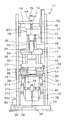
本発明の実施形態について図1ないし図3を参照して説明する。図1は、本実施形態のディスク基板成形機の正面図であって型開時の状態を示す図である。なお図1では射出装置も上昇させた状態を示している。図2は、本実施形態のディスク基板成形機の正面図であって型閉時の状態を示す図である。図3は、本実施形態のディスク基板成形機の要部の拡大断面図である。 An embodiment of the present invention will be described with reference to FIGS. FIG. 1 is a front view of a disk substrate molding machine according to the present embodiment, showing a state when the mold is opened. FIG. 1 shows a state where the injection device is also raised. FIG. 2 is a front view of the disk substrate molding machine according to the present embodiment, and shows a state when the mold is closed. FIG. 3 is an enlarged cross-sectional view of a main part of the disk substrate molding machine according to the present embodiment.
図1ないし図3に示されるように、ディスク基板成形機は、上部に射出装置12が設けられ、下部に型締装置13が設けられた縦型ディスク基板成形機11である。基台14には4本の枠部材15が立設され、前記枠部材15に水平方向に設けられた梁部材16を介して固定盤17が固定されている。固定盤17は、縦型ディスク基板成形機11全体の中では中間の高さに配設されており、前記固定盤17と、固定盤17の下方の受圧盤18との間には4本のタイバ19が配設されている。そして前記タイバ19には可動盤20が固定盤17に対して昇降自在に取付けられている。また可動盤20と受圧盤18の間にはサーボモータ35によって駆動される型開閉機構のトグルリンク21が設けられている。そして可動盤20の内部に型開閉機構とは別に型締機構の型締シリンダ29が配設されている。
As shown in FIGS. 1 to 3, the disk substrate molding machine is a vertical disk
固定盤17の上面には射出装置12の加熱筒22およびノズル23が挿入される擂鉢状の穴24が設けられ、その周囲に射出装置12を昇降させるシフトシリンダ25が2本設けられている。一方固定盤17の下面には固定金型26が固定されている。可動盤20は、上方の第一可動盤27と下方の第二可動盤28の2枚の可動盤20から形成され、いずれの可動盤27,28も四隅近傍がタイバ19に挿通されている。第一可動盤27の上面中央部には可動金型32が取付けられ、第二可動盤28は、背面中央部(下面中央部)にトグルリンク21が取付けられ、内部に型締機構である型締シリンダ29が配設されている。
A mortar-
型締機構について説明すると、型締シリンダ29は復動シリンダであるが、ピストン30は型締側の受圧面積の方が型開側の受圧面積よりも大きく設けられている。ピストン30に固定されるラム31の他端は、第一可動盤27の背面(下面)に固定されている。また第一可動盤27と第二可動盤28の一方の側面には、両者の距離を測定する位置センサ33(MTSセンサ)が配設されている。
The mold clamping mechanism will be described. Although the mold clamping
前記ラム31の直径は、成形されるディスク基板および可動金型32のスタンパ64の直径よりも大きく設けられている。また前記ラム31のストロークは、型締時の移動分と金型変更時の型厚調整分であるので10〜30mm程度であり、従来の油圧式型締機構と比較して極めて少量の油で作動させることができる。また第一可動盤27内およびラム31内には図示は省略するがオスカッタ、突出ピン、およびエジェクタスリーブを作動させる油圧シリンダやエアシリンダとその管路等が設けられている。なお前記オスカッタ、突出ピン、およびエジェクタスリーブや、上記したシフトシリンダ25については、すべてサーボモータとボールネジ機構により前後進するものとしてもよい。
The diameter of the
型締シリンダ29の油圧回路について説明すると、図3に示されるようには、モータにより作動するポンプ41が設けられ、ポンプ41から油が送られる管路42は、チェックバルブ43を介してカートリッジバルブ44に接続されている。そしてカートリッジバルブ44に到る途中の管路42には前記カートリッジバルブ44を作動させるパイロット管路45が設けられ、パイロット管路45には切換バルブ46が配設されている。またカートリッジバルブ44の先にはサーボバルブ47が配設され、サーボバルブ47のAポートとBポートは、管路48、管路49等を介して型締シリンダ29の型開側油室50と型締側油室51に接続されている。そして前記型開側油室50への管路48には圧力センサ52が取付けられ、型締側油室51への管路49には圧力センサ53が取付けられている。またカートリッジバルブ44への管路42から分岐した管路54には、アキュームレータ55が接続されている。またポンプ41とチェックバルブ43との間の管路42は圧力制御バルブ56に接続されている。そしてポンプ41、サーボバルブ47、圧力制御バルブ56等は、油圧タンク57に接続されている。また前記切換バルブ46、サーボバルブ47、圧力制御バルブ56、圧力センサ52,53等はそれぞれ縦型ディスク基板成形機11の制御装置58と電気的に接続されている。なお制御装置58は、型開閉用サーボモータ35、射出用サーボモータ75、計量用サーボモータ78の本体およびエンコーダともサーボアンプ等を介して電気的に接続されている。更には位置センサ33とも電気的に接続されている。
The hydraulic circuit of the
型開閉機構について説明すると、図1、図2に示されるように、型開閉機構のトグルリンク21は、一端が第二可動盤28に取付けられ他端が第2リンク21bに取付けられた第1リンク21a、一端が受圧盤18に取付けられ他端が前記第1リンク21aに取付けられ他端寄りが第3リンク21cに取付けられた第2リンク21b、一端が第2リンク21bに取付けられ、他端がクロスヘッド34に取付けられた第3リンク21cからなっている。また受圧盤18の側方には型開閉機構の型開閉用サーボモータ35がブラケットにより取付けられている。受圧盤18には図示しないベアリングを介してボールネジ36が垂直方向に回転自在に取付けられている。そしてボールネジ36の下端にはプーリ37が水平方向に取付けられ、前記型開閉用サーボモータ35の駆動プーリ38との間にタイミングベルト39が配設されている。ボールネジ36の上方にはクロスヘッド34に固定されたボールネジナット40が配設され、ボールネジ36の回転によりボールネジナット40とクロスヘッド34が昇降移動されるようになっている。そして前記型開閉用サーボモータ35には受圧盤18に対する第二可動盤28の位置を検出するエンコーダ35aが設けられている。
The mold opening / closing mechanism will be described. As shown in FIGS. 1 and 2, the
本実施形態の縦型ディスク基板成形機11では、型開閉は型開閉用サーボモータ35とトグルリンク21等の組合せにより行い、型締は型締シリンダ29により行うので型開閉用サーボモータ35とトグルリンク21を小型化できる。また本実施形態では、成形金型の厚みが変更されても型締シリンダ29のストローク位置調整により対応可能なので、受圧盤18の位置を移動させる型厚調整機構は取付けられていない。
In the vertical disk
図3に示されるように、固定金型26はノズル23が当接され射出される溶融樹脂が通過するスプルブッシュ61、ゲートインサートブロック62、固定鏡面板63等を備えている。そしてゲートインサートブロック62にはメスカッタが形成されている。また可動金型32は、図示しない突出ピン、オスカッタ、エジェクタスリーブと、スタンパ64の内周側を押える内周スタンパホルダ65、スタンパ64の外周側を押える外周スタンパホルダ66、可動鏡面板67等を備えている。そして型閉された際には前記外周スタンパホルダ66の内孔に固定鏡面板63の外周面が嵌合されて容積可変のキャビティ68が形成されるようになっている。なおディスク基板成形金型としては、前記のものに限定されず、固定金型にスタンパが配設されたものでもよく、バネにより進退しディスク基板を形成する側面壁形成部が一方の金型に取付けられ、前記側面壁形成部の前面が他方の金型に当接してキャビティを形成するものでもよい。
As shown in FIG. 3, the fixed
図1、図2に示されるように、4本の枠部材15における一方の2本の梁部材16には射出装置12の昇降移動をガイドするガイド部材71が取付けられている。そしてガイド部材71の上部側は軸72により枠部材15に対して旋回可能となっている。またガイド部材71にはハウジングプレート73とプッシャプレート74が上下方向に摺動自在に取付けられている。ハウジングプレート73の下面には加熱筒22が下方に向けて固定されるとともに、上記シフトシリンダ25のロッドがそれぞれ取付けられている。またハウジングプレート73の両側に水平方向に張出した張出部には射出用サーボモータ75がそれぞれ取付けられている。射出用サーボモータ75の図示しないロータにはボールネジ76が直結され、前記ボールネジ76は、ハウジング内で軸支されるとともに上側はプッシャプレート74に固定されたボールネジナット77に回転自在に挿入されている。また加熱筒22内に配設された図示しないスクリュの後端は、スクリュスリーブに接続され、スクリュスリーブが計量用サーボモータ78のロータに直結されている。またハウジングプレート73の他方面には樹脂材料を加熱筒22内に投入する開口79が形成され、フィードスクリュが配設された供給装置80等を介して図示しない樹脂貯留部に接続されている。従って射出装置12は、射出用サーボモータ75の作動によりハウジングプレート73に対してプッシャプレート74が昇降移動し、それに従いスクリュスリーブおよびスクリュが前後進する。また計量用サーボモータ78の作動により、スクリュスリーブを介してスクリュが回転される。
As shown in FIGS. 1 and 2, a
次に縦型ディスク基板成形機11を用いたブルーレイディスク(登録商標)用のディスク基板(直径120mm、厚さ1.1mm、トラックピッチ0.32μm:いずれの数値も許容成形誤差内のものを含む)の成形について説明する。本実施形態では、射出成形の一分野であって、射出時の射出圧により可動金型32が僅かに後退しその後圧縮を加える射出圧縮成形によりディスク基板成形を行う。まず前回成形サイクルの型開閉中または型開時に可動盤20内の型締シリンダ29のピストン30およびラム31の位置が、最適な位置(偏移量B)となるように位置制御されている。型締シリンダ29のピストン30およびラム31の位置制御は、第二可動盤28に対する第一可動盤27の位置を位置センサ33により検出してサーボバルブ47を制御してクローズドループ制御される。またこの際、型開側油室50と型締側油室51の両方の油室に圧力は一定圧以上となっている。また冷却工程時や前記型締シリンダ29への油の封じ込め後などには、ポンプ41から送られる油がアキュームレータ55に蓄圧される。
Next, a disc substrate for Blu-ray Disc (registered trademark) using the vertical disc substrate molding machine 11 (diameter 120 mm, thickness 1.1 mm, track pitch 0.32 μm: all values are within allowable molding errors. ) Will be described. In this embodiment, which is a field of injection molding, disk substrate molding is performed by injection compression molding in which the
次に制御装置58から型閉信号が送信されることにより型開閉機構の型開閉用サーボモータ35が作動されボールネジ36が回転されると、ボールネジナット40およびクロスヘッド34の上昇とともにトグルリンク21が伸長される。そしてトグルリンク21が設定された位置まで伸長されたことがエンコーダ35aにより検出されると型開閉用サーボモータ35を停止させサーボロック(位置保持)して、型閉が完了する。型閉完了位置におけるトグルリンク21の状態は、トグルリンク21が完全に一直線に伸長される直前であってトグルリンク21が僅かに内側に屈曲された状態である。そして上記したように第二可動盤28に対する第一可動盤27の位置は、既に型締シリンダ29により位置決め制御されているから、型閉完了により固定金型26と可動金型32の間にキャビティ68が形成される。この際の型締力は一例として10〜100kNと比較的低圧となっている。
Next, when a mold closing signal is transmitted from the
そして次に前回の成形時から固定金型26に常時ノズルタッチしている射出装置12のノズル23から340〜380℃、射出速度100〜400mm/sec、射出圧力10〜60MPaのポリカーボネートの溶融樹脂をキャビティ68内に射出する。この際の可動金型32は型閉完了位置に位置保持されているが射出圧により、僅かに後退する。しかし前記可動金型32等の後退分は、型締シリンダ29のストロークによりほとんど吸収される。従ってトグルリンク21は設定された伸長した状態のままであるので、第一可動盤27と受圧盤18との位置関係はほとんど変化なく、サーボモータ35に大きな負荷がかかることはない。
Then, a polycarbonate molten resin having a nozzle temperature of 340 to 380 ° C., an injection speed of 100 to 400 mm / sec, and an injection pressure of 10 to 60 MPa is injected from the
次に射出開始から僅かに遅れて射出装置12のスクリュが所定位置に前進したことが検出されると、制御装置58から切換バルブ46に対して信号が送られ、カートリッジバルブ44が開放され、アキュームレータ55に蓄圧された油とポンプ41からの油がサーボバルブ47を介して型締シリンダ29の型締側油室51に向けて送油される。そして型開側油室50の油はサーボバルブ47を介してドレンに落とされる。この際アキュームレータ55を用いることにより、0.03〜0.07秒で型締シリンダ29の圧力センサ53の値が所定の設定値の16〜19MPaとなるまで昇圧可能となる。そのため型締シリンダ29のラム31は射出圧に打勝って高速で前進され、同時に可動金型32の鏡面板67が、図3において一点鎖線で示される位置まで前進される。よってキャビティ68内の溶融樹脂を急速に圧縮と延展させ良好な転写成形ができる。またラム31によりキャビティ68内の溶融樹脂に対して直接加圧をすることができるので、第一可動盤27が反ることがなく、ラム31の形状および断面積を選択することにより、最良の押圧面積を選択できる。なお本実施形態では水平方向に形成されたキャビティ68に溶融樹脂が延展されるので重力の影響により不均一なディスクが成形されることがない。
Next, when it is detected that the screw of the
そして型締シリンダ29の圧力が前記所定の設定値に到達したことが圧力センサ53(または圧力センサ52,53の差圧)により検出されると、その後は圧力センサ52,53の差圧を検出しサーボバルブ47をクローズドループ制御する圧縮制御(多段圧力フィードバック制御)がなされる。この際に型締シリンダ29により発生する型締力の最高値は、300〜700kNであり、溶融樹脂に対する面圧としては26MPa〜62MPa程度である。またこの際、射出力に打勝つ形でラム31が前進されることにより型締力が上昇され、その結果タイバ19が伸長され受圧盤18が僅かに下降(後退)する。
When the pressure sensor 53 (or the differential pressure between the
上記のように射出圧縮制御時に急速に型締圧力を上昇させるためには、トグルリンクとサーボモータのみを用いた型締機構で行うよりも、サーボバルブ47によって制御される型締シリンダ29で昇圧を行う方が、短い時間で所望の型締力またはキャビティ内圧が得られる。その結果、キャビティ68内で良好な転写成形ができるのでディスク基板には望ましい。そしてキャビティ68内の圧縮とともに射出装置12側は保圧を行う。また保圧中に可動金型32のオスカッタが前進してゲートカットが行われる。キャビティ68内の溶融樹脂の冷却時間が終了すると型締シリンダ29の圧抜が行われる。それと前後して固定金型26および可動金型32から離型エアが噴出される。そして型開閉用サーボモータ35によりトグルリンク21が作動され、型開が行われる。成形されたディスク基板は可動金型32側に取り出され、その後エジェクタスリーブおよび突出ピンにより更に突き出されるとともに、図示しない取出ロボットにより取出される。そして前記のように型締シリンダ29のラム31が所定の位置に戻される。
In order to increase the mold clamping pressure rapidly during injection compression control as described above, the pressure is increased by the
本発明については、上記した本実施形態のものに限定されず、当業者が本発明の趣旨を踏まえて変更を加えたものについても、適用されることは言うまでもないことである。縦型ディスク基板成形機11は設置面積の点やキャビティ68内の溶融樹脂が重力の影響を受けずに均一なディスク基板を成形する上で有利であるが、水平方向に可動盤および可動金型が移動する横型ディスク成形機に本発明を用いても良い。また本実施形態では、下方に向けて射出装置が設けられた縦型ディスク基板成形機について説明したが、射出装置の向きは加熱筒が水平方向に設けられ、ノズルが直角方向に屈曲して下方に向けて設けられたものや水平方向にノズルが設けられ金型内でキャビティへ導かれるものでもよい。更には下方に射出装置が設けられ、上方に型締装置が設けられたものでもよい。
The present invention is not limited to the above-described embodiment, and it goes without saying that the present invention can be applied to those modified by a person skilled in the art based on the gist of the present invention. The vertical disk
またサーボモータによって駆動される型開閉機構としては、ボールネジとボールナットの組合せによりトグルリンクを用いずに型開閉するもの、クランク機構を用いるもの、リニア直動機構を用いるものなど他の方式であってもよい。 The mold opening / closing mechanism driven by the servo motor is another type such as a combination of a ball screw and ball nut that opens and closes without using a toggle link, a crank mechanism, and a linear linear mechanism. May be.
また本実施形態ではブルーレイディスク用のディスク基板の成形について記載したが他のディスク基板の成形にも用いることができる。そしてトグルリンクで型閉した際に成形されるディスク基板の板厚以上に固定金型と可動金型の間隔が僅かに開いた状態でキャビティを形成し、溶融樹脂を射出後に型締シリンダにより可動金型を前進させてキャビティ内の溶融樹脂を圧縮する射出圧縮成形の一分野である射出プレスについても、本発明に使用することができる。射出プレスによる成形は、厚さが薄いDVD等のディスク基板の成形に特に好適に用いられる。射出プレス成形では停止位置から急速に可動金型を前進させるので、通常のトグルリンク機構のみの場合、トグルリンクが屈曲した状態からトグルリンクを伸長させるのにサーボモータに大きな負荷がかかる。しかし本発明ではトグルリンクは既に伸長している状態から型締シリンダを前進させるので、サーボモータの負荷が少ない。また射出と型締側の圧縮の関係は、射出と同時に可動金型を圧縮制御を開始するもの、射出中に圧縮制御を開始するもの、射出後に圧縮制御を開始するものなど各種のタイミングのものが含まれる。 In this embodiment, the formation of a disk substrate for a Blu-ray disc has been described. However, the present invention can also be used for forming other disk substrates. Then, a cavity is formed with the gap between the fixed mold and the movable mold slightly wider than the thickness of the disk substrate that is molded when the mold is closed with a toggle link, and the mold is moved by the mold clamping cylinder after the molten resin is injected. An injection press which is a field of injection compression molding in which a mold is advanced to compress molten resin in a cavity can also be used in the present invention. The molding by the injection press is particularly preferably used for molding a disk substrate such as a DVD having a small thickness. In injection press molding, the movable mold is rapidly advanced from the stop position. Therefore, in the case of only a normal toggle link mechanism, a large load is applied to the servo motor to extend the toggle link from a bent state. However, in the present invention, since the toggle link advances the mold clamping cylinder from the already extended state, the load on the servo motor is small. The relationship between injection and compression on the mold clamping side has various timings such as the one that starts compression control of the movable mold simultaneously with the injection, the one that starts compression control during injection, and the one that starts compression control after injection. Is included.
11 縦型ディスク基板成形機
13 型締装置
17 固定盤
20 可動盤
21 トグルリンク
26 固定金型
27 第一可動盤
28 第二可動盤
29 型締シリンダ
31 ラム
32 可動金型
35 型開閉用サーボモータ
DESCRIPTION OF
Claims (3)
サーボモータによって駆動される型開閉機構と、
サーボバルブによって駆動される型締シリンダを備えた型締機構とが設けられ、
第一可動盤に前記可動金型が配設され、
型開閉機構を構成するトグルリンクが背面に取付けられる第二可動盤に前記型締シリンダが配設され、該型締シリンダのラムが前記第一可動盤の背面に固定され、
前記型締シリンダにはアキュームレータが接続され、前記アキュームレータに蓄圧された油により型締シリンダの昇圧を行い、キャビティ内の溶融樹脂を加圧することを特徴とするディスク基板成形機。 In a disk substrate molding machine that molds a disk substrate by injecting molten resin into a cavity formed between a fixed mold and a movable mold,
A mold opening / closing mechanism driven by a servo motor;
A mold clamping mechanism including a mold clamping cylinder driven by a servo valve;
The movable mold is disposed on the first movable platen,
The mold clamping cylinder is disposed on a second movable plate to which a toggle link constituting a mold opening / closing mechanism is attached to the back surface, and the ram of the mold clamping cylinder is fixed to the back surface of the first movable plate,
An accumulator is connected to the mold clamping cylinder, and the pressure of the mold clamping cylinder is increased by oil accumulated in the accumulator so as to pressurize the molten resin in the cavity .
サーボモータによって駆動される型開閉機構と、
サーボバルブによって駆動される型締シリンダを備えた型締機構とが設けられ、
第一可動盤に前記可動金型が配設され、
型開閉機構を構成するトグルリンクが背面に取付けられる第二可動盤に前記型締シリンダが配設され、該型締シリンダのラムが前記第一可動盤の背面に固定され、
前記ラムの直径は成形されるディスクの直径よりも大きく設けられ、前記型締シリンダにはアキュームレータが接続され、アキュームレータに蓄圧された油により型締シリンダの昇圧を行い、キャビティ内の溶融樹脂を加圧することを特徴とするディスク基板成形方法。 In a disk substrate molding method for molding a disk substrate by injecting molten resin into a cavity formed between a fixed mold and a movable mold,
A mold opening / closing mechanism driven by a servo motor;
A mold clamping mechanism including a mold clamping cylinder driven by a servo valve;
The movable mold is disposed on the first movable platen,
The mold clamping cylinder is disposed on a second movable plate to which a toggle link constituting a mold opening / closing mechanism is attached to the back surface, and the ram of the mold clamping cylinder is fixed to the back surface of the first movable plate,
The diameter of the ram is larger than the diameter of the disk to be molded. An accumulator is connected to the mold clamping cylinder, and the mold clamping cylinder is pressurized with oil accumulated in the accumulator to add molten resin in the cavity. A method for forming a disk substrate, comprising pressing.
Priority Applications (1)
| Application Number | Priority Date | Filing Date | Title |
|---|---|---|---|
| JP2008109705A JP5093809B2 (en) | 2008-04-21 | 2008-04-21 | Disc substrate molding machine and disc substrate molding method |
Applications Claiming Priority (1)
| Application Number | Priority Date | Filing Date | Title |
|---|---|---|---|
| JP2008109705A JP5093809B2 (en) | 2008-04-21 | 2008-04-21 | Disc substrate molding machine and disc substrate molding method |
Publications (2)
| Publication Number | Publication Date |
|---|---|
| JP2009255462A JP2009255462A (en) | 2009-11-05 |
| JP5093809B2 true JP5093809B2 (en) | 2012-12-12 |
Family
ID=41383526
Family Applications (1)
| Application Number | Title | Priority Date | Filing Date |
|---|---|---|---|
| JP2008109705A Expired - Fee Related JP5093809B2 (en) | 2008-04-21 | 2008-04-21 | Disc substrate molding machine and disc substrate molding method |
Country Status (1)
| Country | Link |
|---|---|
| JP (1) | JP5093809B2 (en) |
Families Citing this family (2)
| Publication number | Priority date | Publication date | Assignee | Title |
|---|---|---|---|---|
| JP6339408B2 (en) * | 2014-05-12 | 2018-06-06 | Towa株式会社 | Mold apparatus, compression molding apparatus and compression molding method |
| KR101568641B1 (en) | 2015-01-27 | 2015-11-11 | 대창기계공업 주식회사 | Cylinder apparatus and hybrid type brow molding machine using this |
Family Cites Families (7)
| Publication number | Priority date | Publication date | Assignee | Title |
|---|---|---|---|---|
| JPH02215509A (en) * | 1989-02-17 | 1990-08-28 | Toshiba Mach Co Ltd | Clamping device |
| JP2800379B2 (en) * | 1990-06-30 | 1998-09-21 | 三菱マテリアル株式会社 | Transfer molding machine |
| JP3206889B2 (en) * | 1997-03-19 | 2001-09-10 | 東芝機械株式会社 | Mold clamping devices such as injection molding machines |
| JP3860999B2 (en) * | 2001-12-21 | 2006-12-20 | 三菱重工プラスチックテクノロジー株式会社 | Mold clamping device and mold clamping method of injection compression molding machine |
| JP3913198B2 (en) * | 2003-07-08 | 2007-05-09 | 東洋機械金属株式会社 | Vertical injection molding machine |
| JP4223537B2 (en) * | 2006-08-22 | 2009-02-12 | 株式会社名機製作所 | Mold for molding disk substrate, mirror plate thereof, method for molding disk substrate, and disk substrate |
| JP4671294B2 (en) * | 2006-10-30 | 2011-04-13 | 株式会社名機製作所 | Injection compression molding method for injection molding machine |
-
2008
- 2008-04-21 JP JP2008109705A patent/JP5093809B2/en not_active Expired - Fee Related
Also Published As
| Publication number | Publication date |
|---|---|
| JP2009255462A (en) | 2009-11-05 |
Similar Documents
| Publication | Publication Date | Title |
|---|---|---|
| JP4979636B2 (en) | Injection molding machine and injection molding method | |
| JP5153023B1 (en) | Compression molding method of resin molded product containing fiber | |
| JP4671294B2 (en) | Injection compression molding method for injection molding machine | |
| JP7032188B2 (en) | Injection molding machine | |
| WO2001043942A1 (en) | Resin sealing mold and resin sealing method | |
| JP6797723B2 (en) | Injection molding machine | |
| JP5093809B2 (en) | Disc substrate molding machine and disc substrate molding method | |
| JP2023126444A (en) | Injection molding machine | |
| CN108790010A (en) | Injection (mo(u)lding) machine | |
| JP2008179061A (en) | Injection molding machine and control method thereof | |
| TWI503219B (en) | A thin plate injection molding method and a thin plate injection press forming apparatus | |
| JP2009255463A (en) | Injection molding machine and injection molding method | |
| KR100696026B1 (en) | Clamping apparatus of hydro-mechanical type for injection molding machine | |
| JP4425691B2 (en) | Mold apparatus for injection molding machine and injection molding method | |
| JP5278111B2 (en) | Injection molding machine | |
| KR20170038159A (en) | Injection molding machine | |
| JP5654327B2 (en) | Die casting machine and pressure increase control method for die casting machine | |
| JP3858198B2 (en) | How to adjust warpage of disk substrate | |
| JP7102088B2 (en) | Molding machine control method and molding machine | |
| CN108501298B (en) | Injection molding machine | |
| JP2022131756A (en) | Injection molding machine | |
| JP4502669B2 (en) | Injection molding machine and control method thereof | |
| JP2022157892A (en) | movable platen | |
| JP4089906B2 (en) | Molding monitoring method in pressure filling molding of resin | |
| JP2022149842A (en) | Injection molding machine |
Legal Events
| Date | Code | Title | Description |
|---|---|---|---|
| A977 | Report on retrieval |
Free format text: JAPANESE INTERMEDIATE CODE: A971007 Effective date: 20110916 |
|
| A131 | Notification of reasons for refusal |
Free format text: JAPANESE INTERMEDIATE CODE: A131 Effective date: 20111025 |
|
| A521 | Written amendment |
Free format text: JAPANESE INTERMEDIATE CODE: A523 Effective date: 20111108 |
|
| A131 | Notification of reasons for refusal |
Free format text: JAPANESE INTERMEDIATE CODE: A131 Effective date: 20120709 |
|
| A521 | Written amendment |
Free format text: JAPANESE INTERMEDIATE CODE: A523 Effective date: 20120710 |
|
| TRDD | Decision of grant or rejection written | ||
| A01 | Written decision to grant a patent or to grant a registration (utility model) |
Free format text: JAPANESE INTERMEDIATE CODE: A01 Effective date: 20120912 |
|
| A01 | Written decision to grant a patent or to grant a registration (utility model) |
Free format text: JAPANESE INTERMEDIATE CODE: A01 |
|
| A61 | First payment of annual fees (during grant procedure) |
Free format text: JAPANESE INTERMEDIATE CODE: A61 Effective date: 20120912 |
|
| R150 | Certificate of patent (=grant) or registration of utility model |
Free format text: JAPANESE INTERMEDIATE CODE: R150 |
|
| FPAY | Renewal fee payment (prs date is renewal date of database) |
Free format text: PAYMENT UNTIL: 20150928 Year of fee payment: 3 |
|
| LAPS | Cancellation because of no payment of annual fees |