JP5093035B2 - Image forming apparatus - Google Patents
Image forming apparatus Download PDFInfo
- Publication number
- JP5093035B2 JP5093035B2 JP2008254040A JP2008254040A JP5093035B2 JP 5093035 B2 JP5093035 B2 JP 5093035B2 JP 2008254040 A JP2008254040 A JP 2008254040A JP 2008254040 A JP2008254040 A JP 2008254040A JP 5093035 B2 JP5093035 B2 JP 5093035B2
- Authority
- JP
- Japan
- Prior art keywords
- belt
- driven roller
- tension
- roller
- rotation
- Prior art date
- Legal status (The legal status is an assumption and is not a legal conclusion. Google has not performed a legal analysis and makes no representation as to the accuracy of the status listed.)
- Active
Links
Images


Description
本発明は、画像形成装置に関するものである。 The present invention relates to images forming device.
例えば、特許文献1に記載の電子写真方式の画像形成装置では、画像形成が開始された時に転写搬送用のベルトの張力を増加させ、画像形成終了後にベルトの張力を減少させることにより、画像形成時にベルトが駆動ローラに対して滑ってしまうことを防止している。
ところで、ベルトが駆動ローラに対して滑ってしまうことを防止するには、ベルトに作用する張力を増大させてベルトと駆動ローラとの接触面で発生する摩擦力を増大させることが望ましい。 By the way, in order to prevent the belt from sliding with respect to the driving roller, it is desirable to increase the friction force generated on the contact surface between the belt and the driving roller by increasing the tension acting on the belt.
そこで、発明者は、ベルトの滑りが発生しない程度の張力を常にベルトに付与する構成のベルトユニットを試作検討したが、以下に述べる問題が新たに発生した。
すなわち、ベルトに滑りが発生しない程度の高い張力を常にベルトに付与し続けると、図4に示すように、ベルトBのうち駆動ローラR1及び従動ローラR2に接触していた部分に、これらローラの外周形状に沿うような曲がり癖や永久歪みが発生する可能性がある。そして、ベルトに曲がり癖等が発生すると、ベルトの送り精度(移動精度)が低下してしまい、画像形成に悪影響を及ぼしてしまう可能性がある。
Therefore, the inventor has made a trial production of a belt unit configured to always apply tension to the belt so as not to cause slippage of the belt. However, the following problems have newly occurred.
That is, if a high tension that does not cause slippage of the belt is continuously applied to the belt, the portions of the belt B that have been in contact with the driving roller R1 and the driven roller R2 as shown in FIG. There is a possibility that curled wrinkles and permanent distortions occur along the outer peripheral shape. If the belt is bent or wrinkled, the belt feeding accuracy (movement accuracy) is lowered, which may adversely affect image formation.
本発明は、上記点に鑑み、ベルトの滑りを抑制しつつ、ベルトの曲がり癖等に起因するベルトの送り精度(移動精度)の低下を防止することを目的とする。 The present invention has been made in view of the above points, and an object of the present invention is to prevent a decrease in belt feeding accuracy (movement accuracy) due to bending of the belt while suppressing belt slippage.
本発明は、上記目的を達成するために、請求項1に記載の発明では、画像形成手段と、無端状のベルトと、ベルトを回転駆動する駆動ローラと、駆動ローラとの間でベルトが架け渡され、ベルトの回転と共に従動回転する従動ローラと、従動ローラの回転時に従動ローラに回転抵抗を付与する回転抵抗付与手段とを備えることを特徴とする。
In order to achieve the above object, according to the present invention, in the invention described in
これにより、請求項1に記載の発明では、駆動ローラが回転してベルト及び従動ローラが回転すると、従動ローラには大きな負荷(回転抵抗)が作用するので、駆動ローラは、従動ローラに作用する大きな負荷(回転抵抗)に逆らってベルトを強制的に回転させるので、ベルトに大きな張力が発生する。 Thus, in the first aspect of the invention, when the driving roller rotates and the belt and the driven roller rotate, a large load (rotational resistance) acts on the driven roller, so the driving roller acts on the driven roller. Since the belt is forcibly rotated against a large load (rotational resistance), a large tension is generated on the belt.
一方、駆動ローラの回転が停止すると、従動ローラに作用する大きな負荷(回転抵抗)が消失するので、駆動ローラの回転に伴った発生した張力は、駆動ローラの停止と同時に消失する。 On the other hand, when the rotation of the driving roller stops, a large load (rotational resistance) acting on the driven roller disappears, so that the tension generated with the rotation of the driving roller disappears simultaneously with the stop of the driving roller.
つまり、請求項1に記載の発明では、駆動ローラが回転し始めると、これに連動して従動ローラの回転抵抗が増大してベルトの張力が増大し、一方、駆動ローラが停止すると、これに連動して増大した張力が以前の大きさに戻る。 In other words, in the first aspect of the invention, when the driving roller starts to rotate, the rotational resistance of the driven roller increases in conjunction with this, and the belt tension increases. On the other hand, when the driving roller stops, The increased tension is restored to the previous magnitude.
したがって、駆動ローラの停止時には、ベルトの張力を曲がり癖等が発生しない程度の大きさとし、駆動ローラの回転時には、ベルトの張力を滑りが発生しない程度の大きさとすることが可能であるので、画像形成が開始されたか否かを検出・判定することなく、ベルトの滑りを抑制しつつ、ベルトの曲がり癖等に起因するベルトの送り精度(移動精度)の低下を防止することができる。 Therefore, when the drive roller is stopped, the belt tension can be set to a level that does not cause bending or wrinkles, and when the drive roller rotates, the belt tension can be set to a level that does not cause slippage. Without detecting / determining whether or not the formation has been started, it is possible to prevent the belt from slipping and to prevent the belt feeding accuracy (movement accuracy) from being lowered due to bending of the belt.
また、請求項1に記載の発明では、従動ローラの回転軸は、その軸方向と略直交する方向に変位可能に支持されており、さらに、ベルトに発生する張力が増大する向きの力を回転軸に作用させる付勢手段が備えられていることも特徴とする。 According to the first aspect of the present invention, the rotation shaft of the driven roller is supported so as to be displaceable in a direction substantially perpendicular to the axial direction, and further rotates the force in the direction in which the tension generated in the belt increases. A biasing means for acting on the shaft is also provided.
これにより、請求項1に記載の発明では、ベルトに張力を付与するテンションローラに回転抵抗が付与される構成となるので、効果的にベルトの滑りを抑制できる。
また、請求項1に記載の発明では、回転抵抗付与手段は、従動ローラと一体的に回転する回転体、及び回転体に回転抵抗を付与するダンピング手段を有して構成されており、さらに、回転軸は、ダンピング手段が回転体に回転抵抗を付与する際に発生する反力により、ベルトに発生する張力が増大する向きの力を受けることも特徴とする。
Accordingly, in the invention according to the first aspect , since the rotation resistance is applied to the tension roller that applies tension to the belt, the belt slip can be effectively suppressed.
In the invention described in
これにより、請求項1に記載の発明では、従動ローラに回転抵抗を付与することによる張力の増大機能に加えて、回転軸を変位させることによる張力の増大機能が作用するので、確実にベルトの滑りを抑制できる。
Accordingly, in the invention described in
また、請求項1に記載の発明では、ダンピング手段は、回転体の外周部に形成された歯車部に噛み合って回転しながら回転体に回転抵抗力を付与し、さらに、ダンピング手段は、ダンピング手段と回転体との噛み合い部で発生する反力により、ベルトに発生する張力が増大する向きの成分が含まれるように配置されていることも特徴とする。 In the first aspect of the present invention, the damping means applies a rotational resistance force to the rotating body while meshing with a gear portion formed on the outer peripheral portion of the rotating body, and further the damping means includes the damping means. It is also characterized in that it is arranged so as to include a component in a direction in which the tension generated in the belt increases due to the reaction force generated at the meshing portion between the rotating body and the rotating body.
これにより、請求項1に記載の発明では、回転軸を変位させることによる張力の増大機能を確実に発揮させることができる。
なお、従動ローラで発生する回転抵抗値は、請求項2に記載の発明のごとく、駆動ローラとベルトとの接触部で滑りが発生する限界抵抗値の略50%となるように設定することが望ましい。
Thereby, in the invention described in
The rotational resistance value generated by the driven roller may be set to be approximately 50% of the limit resistance value at which slippage occurs at the contact portion between the driving roller and the belt, as in the second aspect of the invention. desirable.
また、請求項1又は2に記載の発明は、請求項3に記載のごとく、熱可塑性エラストマー製のベルトを用いた画像形成装置に適用すると、特に、好適である。
The invention described in
本実施形態は、画像形成装置用のベルトユニットに本発明に係るベルトユニットを適用したものであり、以下に本発明の実施形態を図面と共に説明する。
(第1実施形態)
1.図面の説明
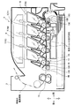
図1は本実施形態に係る画像形成装置1の概略構成を示す中央断面図であり、図2(a)は本実施形態に係るベルトユニット13の特徴を示す図であり、図2(b)は図2(a)の右側面図であり、図3(a)〜図3(d)は、第1基準線Loと第2基準線L2とのなす角と反力F1との関係を示す図である。
In this embodiment, a belt unit according to the present invention is applied to a belt unit for an image forming apparatus, and the embodiment of the present invention will be described below with reference to the drawings.
(First embodiment)
1. FIG. 1 is a central sectional view showing a schematic configuration of an
2.画像形成装置の構成
2.1.画像形成装置の概略構造
画像形成装置1の筐体3内には、図1に示すように、記録用紙やOHPシート等の記録シート(以下、用紙という。)に現像剤像を転写することにより、用紙に画像を形成する電子写真方式の画像形成部5が収納されており、この画像形成部5は、周知のごとく、プロセスカートリッジ7、露光器9及び定着器11等から構成されている。
2. Configuration of image forming apparatus 2.1. Schematic Structure of Image Forming Apparatus In the housing 3 of the
なお、本実施形態に係る画像形成装置1は、ダイレクトタンデム方式のカラーレーザプリンタであるため、用紙の搬送方向に沿って直列に複数個(本実施形態では、4個)のプロセスカートリッジ7が配設されている。
Since the
具体的には、用紙の搬送方向上流側から順に、ブラック用のプロセスカートリッジ7K、イエロー用のプロセスカートリッジ7Y、マゼンタ用のプロセスカートリッジ7M、シアン用のプロセスカートリッジ7Cである。
Specifically, the
そして、各プロセスカートリッジ7K〜7Cは、収納されている現像剤の色が異なるのみで、その構造等は略同一であり、具体的には、各プロセスカートリッジ7K〜7Cは、現像剤像が担持される感光ドラム7A、及び感光ドラム7Aを帯電させる帯電器7B等から構成されている。
The
また、用紙を搬送する転写ベルト13を挟んで感光ドラム7Aと対向する位置には、感光ドラム7Aに担持された現像剤を、静電吸引力を利用して用紙に転写させる転写ローラ15が設けられている。なお、図1においては、紙面の都合上、シアン用のプロセスカートリッジ7Cに関する感光ドラム7A、帯電器7B及び転写ローラ15のみの符号を付した。
In addition, a
以上に説明した構成において、帯電した感光ドラム7Aを露光器9にて露光して感光ドラム7Aの外周面に静電潜像を形成した後、電荷を帯びた現像剤を感光ドラム7Aに供給すると、感光ドラム7Aの外周面に現像剤像が担持(形成)される。そして、感光ドラム7Aに担持されていた現像剤像は、転写ローラ15により用紙に転写された後、定着器11に搬送されて加熱され、用紙に溶着(定着)する。
In the configuration described above, when the charged photosensitive drum 7A is exposed by the
3.ベルトユニット
3.1.ベルトユニットの概要
ベルトユニット13は、転写ベルト13A、駆動ローラ13B、従動ローラ13C、並びに駆動ローラ13B及び従動ローラ13Cを保持するフレーム(図示せず。)等から構成されており、このベルトユニット13は、装置本体に対して着脱可能に組み付けられている。
3. Belt unit 3.1. Outline of Belt Unit The
そして、転写ベルト13Aは、樹脂材料(本実施形態では、熱可塑性エラストマー)からなる無端状のベルト部材であって、駆動ローラ13Bと従動ローラ13Cとの間に架け渡されている。
The
また、駆動ローラ13Bは、装置本体に設けられた電動モータ(図示せず。)等の駆動源から動力を得て回転することにより転写ベルト13Aを回転させ、従動ローラ13Cは転写ベルト13Aの回転と共に従動回転する。
The
そして、従動ローラ13Cの回転軸13Dは、その軸方向と直交する方向であって、転写ベルト13Aに発生する張力が増減する方向(本実施形態では、図1の左右方向)に変位可能にフレームに組み付けられているとともに、圧縮コイルバネ13E等の弾性付勢手段により張力が増大する向き(本実施形態では、図1の右向き)の力を受けている。
The
このため、本実施形態では、従動ローラ13Cは、転写ベルト13Aに所定の張力を発生させるテンションローラとして機能し、転写ベルト13Aは、転写ベルト13Aと駆動ローラ13Bとの接触部で発生する摩擦力により、駆動ローラ13Bに対して滑ることなく一体的に同一速度で回転する。
Therefore, in this embodiment, the driven
3.2.回転抵抗付与機構(図2参照)
回転抵抗付与機構16は、従動ローラ13Cの回転時に従動ローラ13Cに回転抵抗を付与する回転抵抗付与手段であり、この回転抵抗付与機構16は、図2(a)に示すように、従動ローラ13Cの軸方向両端側に設けられ、かつ、従動ローラ13Cと一体的に回転する抵抗回転体16A、及びこの抵抗回転体16Aに回転抵抗を付与するダンパー16B等から構成されている。
3.2. Rotation resistance application mechanism (see Fig. 2)
The rotation
すなわち、抵抗回転体16Aは、円柱又は円筒状のものであって従動ローラ13Cと一体化されており、この抵抗回転体16Aの外周面のうちダンパー16B側には、平歯車状の歯車部16Dが設けられている。
That is, the
そして、抵抗回転体16Aの歯車部16D側には、図2(b)に示すように、歯車部16Dに噛み合って回転しながら抵抗回転体16Aに回転抵抗力を付与するダンパー16Bが設けられている。なお、ダンパー16Bは、内部に封入されたオイルの粘性抵抗を利用して回転抵抗を発生させるダンピング手段である。
Further, as shown in FIG. 2B, a
このため、従動ローラ13Cが回転して抵抗回転体16Aが回転すると、これに機械的に連動してダンパー16Bも回転するため、従動ローラ13Cに回転抵抗を付与され、一方、従動ローラ13Cの回転が停止すると、これに機械的に連動してダンパー16Bの回転も停止するため、従動ローラ13Cに付与されていた回転抵抗も消失する。
For this reason, when the driven
また、ダンパー16Bは、ダンパー16Bと抵抗回転体16A(歯車部16D)との噛み合い部で発生する反力F1により、転写ベルト13Aに発生する張力が増大する向き(矢印Aで示す向き)の成分が含まれるように配置されている。
Further, the
すなわち、抵抗回転体16Aは、その噛み合い部において、図2(b)に示すように、抵抗回転体16Aの回転の向きと反対向きの力をダンパー16Bから反力F1として受ける。
That is, as shown in FIG. 2B, the
このとき、反力F1は、歯車部16Dとダンパー16Bとの噛み合い部で発生する力であるので、その方向は、抵抗回転体16Aの回転中心O1とダンパー16Bの回転中心O2とを通る第1基準線Loと直交する方向L1に対して、歯車部16Dの圧力角αに相当する角度だけ傾いた方向である。
At this time, since the reaction force F1 is a force generated at the meshing portion of the
そこで、本実施形態は、第1基準線L1と第2基準線L2とのなす角が圧力角αとなり、かつ、駆動ローラ13B側から従動ローラ13C側に向かう向きの反力F1が抵抗回転体16Aに作用するようにダンパー16Bを配置している。
Therefore, in the present embodiment, the angle formed by the first reference line L1 and the second reference line L2 becomes the pressure angle α, and the reaction force F1 in the direction from the driving
なお、第2基準線L2とは、転写ベルト13Aに発生する張力の方向と直交する方向(図2(b)の左右方向)と平行であって、抵抗回転体16Aの回転中心O1を通る仮想線をいう。
Note that the second reference line L2 is parallel to a direction perpendicular to the direction of the tension generated in the
4.本実施形態に係る画像形成装置(特に、ベルトユニット)の特徴
本実施形態では、前述したように、駆動ローラ13Bが回転して転写ベルト13A及び従動ローラ13Cが回転すると、従動ローラ13Cには大きな負荷(回転抵抗)が作用する。このため、駆動ローラ13Bは、従動ローラ13Cに作用する大きな負荷(回転抵抗)に逆らって転写ベルト13Aを強制的に回転させるので、転写ベルト13Aに大きな張力が発生する。
4). Features of Image Forming Apparatus (Particularly Belt Unit) According to this Embodiment In this embodiment, as described above, when the driving
一方、駆動ローラ13Bの回転が停止すると、従動ローラ13Cに作用する大きな負荷(回転抵抗)が消失するので、駆動ローラ13Bの回転に伴った発生した張力は、駆動ローラ13Bの停止と同時に消失する。
On the other hand, when the rotation of the driving
つまり、本実施形態では、駆動ローラ13Bが回転し始めると、これに連動して従動ローラ13Cの回転抵抗が増大して転写ベルト13Aの張力が増大し、一方、駆動ローラ13Bが停止すると、これに連動して増大した張力が以前の大きさに戻る。
That is, in this embodiment, when the driving
したがって、駆動ローラ13Bの停止時には、転写ベルト13Aの張力を曲がり癖等が発生しない程度の大きさとし、駆動ローラ13Bの回転時には、転写ベルト13Aの張力を滑りが発生しない程度の大きさとすることが可能であるので、画像形成が開始されたか否かを検出・判定することなく、転写ベルト13Aの滑りを抑制しつつ、転写ベルト13Aの曲がり癖等に起因する転写ベルト13Aの送り精度(移動精度)の低下を防止することができる。
Therefore, when the driving
このとき、従動ローラ13Cで発生する回転抵抗値は、駆動ローラ13Bと転写ベルト13Aとの接触部で滑りが発生する限界抵抗値の略50%となるように設定することが望ましい。
At this time, it is desirable that the rotational resistance value generated at the driven
また、本実施形態では、従動ローラ13Cは転写ベルト13Aに張力を付与するテンションローラとして機能し、かつ、このテンションローラをなす従動ローラ13Cに回転抵抗を付与するので、効果的に転写ベルト13Aの滑りを抑制できる。
In this embodiment, the driven
すなわち、本実施形態では、従動ローラ13Cが回転して抵抗回転体16Aが回転すると、前述したように、従動ローラ13C(回転軸13D)には反力F1が作用する。
このとき、従動ローラ13Cの回転軸13Dは、その軸方向と略直交する方向に変位可能に支持されているので、反力F1により従動ローラ13Cが駆動ローラ13Bから離間するように変位する。したがって、転写ベルト13Aの張力が増大するので、効果的に転写ベルト13Aの滑りを抑制できる。
That is, in this embodiment, when the driven
At this time, since the
このように、本実施形態では、従動ローラ13Cに回転抵抗を付与することによる張力の増大機能に加えて、回転軸13D(従動ローラ13C)を変位させることによる張力の増大機能が作用するので、転写ベルト13Aの滑りを確実に抑制することができる。
Thus, in this embodiment, in addition to the function of increasing the tension by imparting rotational resistance to the driven
なお、反力F1により従動ローラ13Cが変位するのに対してダンパー16Bは不動であるものの、従動ローラ13Cの変位量は微量であるので、ダンパー16Bと歯車部16Dとの噛み合いが外れることはない。
Although the driven
そして、本実施形態に係る歯車部16Dの圧力角αは20°であるので、噛み合い部で発生する反力F1を利用して転写ベルト13Aに発生する張力を増大させるにあたって、第1基準線Loと第2基準線L2とのなす角を20°とすることにより、図3(b)に示すように、噛み合い部で発生する反力F1を効果的に転写ベルト13Aの張力を増大させるために利用している。
Since the pressure angle α of the
なお、図3(a)、図3(c)、図3(d)に示すように、第1基準線Loと第2基準線L2とのなす角を20°以外としても、転写ベルト13Aの張力が増大する向きの成分を発生させることができるが、圧力角α以外の角度を用いると、噛み合い部で発生する反力F1を効果的に利用できない。
As shown in FIGS. 3 (a), 3 (c), and 3 (d), even if the angle formed by the first reference line Lo and the second reference line L2 is other than 20 °, the
(その他の実施形態)
上述の実施形態では、従動ローラ13Cはテンションローラを兼ねるものであったが、本発明はこれに限定されるものではなく、従動ローラ13Cとは別にテンションローラを設けてもよい。
(Other embodiments)
In the above-described embodiment, the driven
また、上述の実施形態では、回転抵抗付与機構16を従動ローラ13Cの軸方向両端側に設けたが、これは、回転抵抗を従動ローラ13Cに付与する際に、従動ローラ13Cが駆動ローラ13Bに対して大きく傾いてしまうことを防止するためである。
In the above-described embodiment, the rotation
しかし、従動ローラ13Cの剛性を十分に大きくする、又は従動ローラ13Cが駆動ローラ13Bに対して傾くこと防止する傾き防止ガイドを設ける等の手段を講じれば、回転抵抗付与機構16を軸方向一端側のみに設けてもよい。
However, if measures such as providing a tilt prevention guide for sufficiently increasing the rigidity of the driven
また、上述の実施形態では、ダンパー16Bはオイルの粘性抵抗を利用したものであったが、本発明はこれに限定されるものではなく、例えば摩擦抵抗を利用したものであってもよい。
In the above-described embodiment, the
また、上述の実施形態では、ダンパー16Bにより抵抗回転体16A(従動ローラ13C)に回転抵抗を付与したが、本発明はこれに限定されるものではなく、例えば、抵抗回転体16A(従動ローラ13C)を回転可能に支持する軸受にて所定の回転抵抗が発生するような構成としてもよい。
In the above-described embodiment, the rotational resistance is applied to the
また、上述の実施形態では、第1基準線Loと第2基準線L2とのなす角を20°としたが、本発明はこれに限定されるものではなく、図3(a)、図3(c)、図3(d)に示すように、第1基準線Loと第2基準線L2とのなす角を20°(圧力角α)以外の角度としてもよい。 In the above-described embodiment, the angle formed by the first reference line Lo and the second reference line L2 is 20 °. However, the present invention is not limited to this, and FIG. 3 (a) and FIG. As shown in FIG. 3C and FIG. 3D, the angle formed by the first reference line Lo and the second reference line L2 may be an angle other than 20 ° (pressure angle α).
また、上述の実施形態では、本発明に係るベルトユニットをダイレクトタンデム方式の画像形成装置に適用したが、本発明の適用はこれに限定されるものではなく、例えば画像形成装置以外のベルトユニット又はダイレクトタンデム方式以外の画像形成装置にも適用できる。 In the above-described embodiment, the belt unit according to the present invention is applied to the direct tandem image forming apparatus. However, the application of the present invention is not limited to this, and for example, a belt unit other than the image forming apparatus or The present invention can also be applied to image forming apparatuses other than the direct tandem system.
また、本発明は、特許請求の範囲に記載された発明の趣旨に合致するものであればよく、上述の実施形態に限定されるものではない。 Further, the present invention is not limited to the above-described embodiment as long as it matches the gist of the invention described in the claims.
1…画像形成装置、5…画像形成部、7…プロセスカートリッジ、9…露光器、
11…定着器、13…ベルトユニット、13A…転写ベルト、13B…駆動ローラ、
13C…従動ローラ、13D…回転軸、15…転写ローラ、
16…回転抵抗付与機構、16A…抵抗回転体、16B…ダンパー、
16D…歯車部。
DESCRIPTION OF
DESCRIPTION OF
13C ... driven roller, 13D ... rotating shaft, 15 ... transfer roller,
16 ... Rotation resistance applying mechanism, 16A ... Resistance rotator, 16B ... Damper,
16D: Gear portion.
Claims (3)
無端状のベルトと、
前記ベルトを回転駆動する駆動ローラと、
前記駆動ローラとの間で前記ベルトが架け渡され、前記ベルトの回転と共に従動回転する従動ローラと、
前記従動ローラの回転時に前記従動ローラに回転抵抗を付与する回転抵抗付与手段と、
前記ベルトに張力を発生させる向きの力を前記従動ローラの回転軸に作用させる付勢手段とを備え、
前記従動ローラの回転軸が当該回転軸の軸方向と略直交する方向に変位可能に支持され、かつ、前記回転軸が前記付勢手段から前記ベルトに張力を発生させる向きの力を受けることにより、前記従動ローラは、前記ベルトに張力を発生させるテンションローラとして機能し、
前記回転抵抗付与手段は、前記従動ローラと一体的に回転する回転体、及び前記回転体に回転抵抗を付与するダンピング手段を有して構成され、
前記ダンピング手段は、前記回転体の外周部に形成された歯車部に噛み合って回転しながら前記回転体に回転抵抗力を付与し、
さらに、前記ダンピング手段は、当該ダンピング手段と前記回転体との噛み合い部で発生する反力により、前記従動ローラの回転軸に対して前記ベルトに発生する張力が増大する向きの成分が含まれるように配置されていることを特徴とする画像形成装置。 Image forming means;
An endless belt,
A driving roller for rotating the belt;
A driven roller that is laid across the belt between the drive rollers and that rotates following the rotation of the belt;
Rotation resistance applying means for applying rotation resistance to the driven roller when the driven roller rotates;
Biasing means for causing a force in a direction to generate tension on the belt to act on the rotation shaft of the driven roller;
The rotation shaft of the driven roller is supported so as to be displaceable in a direction substantially perpendicular to the axial direction of the rotation shaft, and the rotation shaft receives a force in a direction to generate tension on the belt from the biasing means. The driven roller functions as a tension roller that generates tension on the belt,
The rotation resistance applying means includes a rotating body that rotates integrally with the driven roller, and a damping means that applies rotation resistance to the rotating body,
The damping means imparts a rotational resistance force to the rotating body while meshing with a gear portion formed on the outer peripheral portion of the rotating body and rotating,
Further, the damping means includes a component in a direction in which the tension generated in the belt increases with respect to the rotation shaft of the driven roller due to a reaction force generated at a meshing portion between the damping means and the rotating body. An image forming apparatus, wherein
Priority Applications (1)
| Application Number | Priority Date | Filing Date | Title |
|---|---|---|---|
| JP2008254040A JP5093035B2 (en) | 2008-09-30 | 2008-09-30 | Image forming apparatus |
Applications Claiming Priority (1)
| Application Number | Priority Date | Filing Date | Title |
|---|---|---|---|
| JP2008254040A JP5093035B2 (en) | 2008-09-30 | 2008-09-30 | Image forming apparatus |
Publications (2)
| Publication Number | Publication Date |
|---|---|
| JP2010085665A JP2010085665A (en) | 2010-04-15 |
| JP5093035B2 true JP5093035B2 (en) | 2012-12-05 |
Family
ID=42249686
Family Applications (1)
| Application Number | Title | Priority Date | Filing Date |
|---|---|---|---|
| JP2008254040A Active JP5093035B2 (en) | 2008-09-30 | 2008-09-30 | Image forming apparatus |
Country Status (1)
| Country | Link |
|---|---|
| JP (1) | JP5093035B2 (en) |
Family Cites Families (11)
| Publication number | Priority date | Publication date | Assignee | Title |
|---|---|---|---|---|
| JPH11305504A (en) * | 1998-04-23 | 1999-11-05 | Mita Ind Co Ltd | Transferring/feeding device and image forming device having the device |
| JP2000293049A (en) * | 1999-04-05 | 2000-10-20 | Sharp Corp | Image forming device |
| JP3975025B2 (en) * | 1999-04-08 | 2007-09-12 | 株式会社リコー | Wet image forming device |
| JP2001100541A (en) * | 1999-09-28 | 2001-04-13 | Casio Electronics Co Ltd | Tandem color image forming device |
| JP3711827B2 (en) * | 1999-12-24 | 2005-11-02 | カシオ電子工業株式会社 | Image forming apparatus |
| JP2001215809A (en) * | 2000-01-28 | 2001-08-10 | Ricoh Co Ltd | Belt carrying device and image forming apparatus |
| JP4049992B2 (en) * | 2000-12-27 | 2008-02-20 | 株式会社リコー | Rotation drive device and image forming apparatus |
| JP2002258629A (en) * | 2001-03-06 | 2002-09-11 | Ricoh Co Ltd | Image forming apparatus |
| JP4315045B2 (en) * | 2004-04-23 | 2009-08-19 | 油化電子株式会社 | Belt for image forming apparatus and image forming apparatus |
| JP4655696B2 (en) * | 2005-03-09 | 2011-03-23 | 富士ゼロックス株式会社 | Image forming apparatus |
| JP4645711B2 (en) * | 2008-09-16 | 2011-03-09 | ブラザー工業株式会社 | Image forming apparatus |
-
2008
- 2008-09-30 JP JP2008254040A patent/JP5093035B2/en active Active
Also Published As
| Publication number | Publication date |
|---|---|
| JP2010085665A (en) | 2010-04-15 |
Similar Documents
| Publication | Publication Date | Title |
|---|---|---|
| JP4218509B2 (en) | Sheet material feeding device | |
| JP6233698B2 (en) | Belt device, fixing device and image forming apparatus | |
| JP5724358B2 (en) | Conveying apparatus and image forming apparatus | |
| JP2011059537A (en) | Fixing device and image forming apparatus | |
| JP6355432B2 (en) | Belt unit and image forming apparatus including the same | |
| JP4609564B2 (en) | Belt unit and image forming apparatus | |
| US9388000B2 (en) | Spacing mechanism for spacing two members, and a fixing device sheet feeding-conveying device and image forming apparatus incorporating same | |
| JP5305008B2 (en) | Developing device, process unit, and image forming apparatus | |
| JP4911207B2 (en) | Image forming apparatus and belt unit | |
| JP4645711B2 (en) | Image forming apparatus | |
| JP5326960B2 (en) | Image forming apparatus | |
| JP5093035B2 (en) | Image forming apparatus | |
| JP2011059590A (en) | Fixing device and image forming apparatus | |
| JP4310303B2 (en) | Image forming apparatus | |
| JP5371621B2 (en) | Driving device and image forming apparatus | |
| JP6501509B2 (en) | Space adjustment mechanism and image forming apparatus | |
| JP2018194736A5 (en) | Photoconductor unit | |
| JP5915575B2 (en) | Image forming apparatus | |
| JP2008239304A (en) | Sheet feeding device and image formation device | |
| JP5660101B2 (en) | Belt device and image forming apparatus | |
| JP6743757B2 (en) | Fixing device and image forming apparatus | |
| JP5343412B2 (en) | Charging device | |
| JP2009271361A (en) | Belt drive device, transfer device, transfer fixing device, and image forming apparatus | |
| JP2010020134A (en) | Image forming device | |
| JP2011191631A (en) | Image forming apparatus |
Legal Events
| Date | Code | Title | Description |
|---|---|---|---|
| A131 | Notification of reasons for refusal |
Free format text: JAPANESE INTERMEDIATE CODE: A131 Effective date: 20111025 |
|
| A977 | Report on retrieval |
Free format text: JAPANESE INTERMEDIATE CODE: A971007 Effective date: 20111026 |
|
| A521 | Written amendment |
Free format text: JAPANESE INTERMEDIATE CODE: A523 Effective date: 20111216 |
|
| A131 | Notification of reasons for refusal |
Free format text: JAPANESE INTERMEDIATE CODE: A131 Effective date: 20120605 |
|
| A521 | Written amendment |
Free format text: JAPANESE INTERMEDIATE CODE: A523 Effective date: 20120724 |
|
| TRDD | Decision of grant or rejection written | ||
| A01 | Written decision to grant a patent or to grant a registration (utility model) |
Free format text: JAPANESE INTERMEDIATE CODE: A01 Effective date: 20120821 |
|
| A01 | Written decision to grant a patent or to grant a registration (utility model) |
Free format text: JAPANESE INTERMEDIATE CODE: A01 |
|
| A61 | First payment of annual fees (during grant procedure) |
Free format text: JAPANESE INTERMEDIATE CODE: A61 Effective date: 20120903 |
|
| R150 | Certificate of patent or registration of utility model |
Ref document number: 5093035 Country of ref document: JP Free format text: JAPANESE INTERMEDIATE CODE: R150 Free format text: JAPANESE INTERMEDIATE CODE: R150 |
|
| FPAY | Renewal fee payment (event date is renewal date of database) |
Free format text: PAYMENT UNTIL: 20150928 Year of fee payment: 3 |