JP5092346B2 - Sauna device that suppresses sweating and widens pores - Google Patents
Sauna device that suppresses sweating and widens pores Download PDFInfo
- Publication number
- JP5092346B2 JP5092346B2 JP2006287284A JP2006287284A JP5092346B2 JP 5092346 B2 JP5092346 B2 JP 5092346B2 JP 2006287284 A JP2006287284 A JP 2006287284A JP 2006287284 A JP2006287284 A JP 2006287284A JP 5092346 B2 JP5092346 B2 JP 5092346B2
- Authority
- JP
- Japan
- Prior art keywords
- air
- heating
- temperature
- sweating
- sauna
- Prior art date
- Legal status (The legal status is an assumption and is not a legal conclusion. Google has not performed a legal analysis and makes no representation as to the accuracy of the status listed.)
- Active
Links
Images


Classifications
-
- A—HUMAN NECESSITIES
- A61—MEDICAL OR VETERINARY SCIENCE; HYGIENE
- A61H—PHYSICAL THERAPY APPARATUS, e.g. DEVICES FOR LOCATING OR STIMULATING REFLEX POINTS IN THE BODY; ARTIFICIAL RESPIRATION; MASSAGE; BATHING DEVICES FOR SPECIAL THERAPEUTIC OR HYGIENIC PURPOSES OR SPECIFIC PARTS OF THE BODY
- A61H33/00—Bathing devices for special therapeutic or hygienic purposes
- A61H33/06—Artificial hot-air or cold-air baths; Steam or gas baths or douches, e.g. sauna or Finnish baths
- A61H33/063—Heaters specifically designed therefor
-
- A—HUMAN NECESSITIES
- A61—MEDICAL OR VETERINARY SCIENCE; HYGIENE
- A61H—PHYSICAL THERAPY APPARATUS, e.g. DEVICES FOR LOCATING OR STIMULATING REFLEX POINTS IN THE BODY; ARTIFICIAL RESPIRATION; MASSAGE; BATHING DEVICES FOR SPECIAL THERAPEUTIC OR HYGIENIC PURPOSES OR SPECIFIC PARTS OF THE BODY
- A61H33/00—Bathing devices for special therapeutic or hygienic purposes
- A61H33/06—Artificial hot-air or cold-air baths; Steam or gas baths or douches, e.g. sauna or Finnish baths
- A61H33/10—Devices on tubs for steam baths
-
- A—HUMAN NECESSITIES
- A61—MEDICAL OR VETERINARY SCIENCE; HYGIENE
- A61H—PHYSICAL THERAPY APPARATUS, e.g. DEVICES FOR LOCATING OR STIMULATING REFLEX POINTS IN THE BODY; ARTIFICIAL RESPIRATION; MASSAGE; BATHING DEVICES FOR SPECIAL THERAPEUTIC OR HYGIENIC PURPOSES OR SPECIFIC PARTS OF THE BODY
- A61H2201/00—Characteristics of apparatus not provided for in the preceding codes
- A61H2201/50—Control means thereof
- A61H2201/5007—Control means thereof computer controlled
-
- A—HUMAN NECESSITIES
- A61—MEDICAL OR VETERINARY SCIENCE; HYGIENE
- A61H—PHYSICAL THERAPY APPARATUS, e.g. DEVICES FOR LOCATING OR STIMULATING REFLEX POINTS IN THE BODY; ARTIFICIAL RESPIRATION; MASSAGE; BATHING DEVICES FOR SPECIAL THERAPEUTIC OR HYGIENIC PURPOSES OR SPECIFIC PARTS OF THE BODY
- A61H2201/00—Characteristics of apparatus not provided for in the preceding codes
- A61H2201/50—Control means thereof
- A61H2201/5023—Interfaces to the user
- A61H2201/5043—Displays
Landscapes
- Health & Medical Sciences (AREA)
- Public Health (AREA)
- Epidemiology (AREA)
- Pain & Pain Management (AREA)
- Physical Education & Sports Medicine (AREA)
- Rehabilitation Therapy (AREA)
- Life Sciences & Earth Sciences (AREA)
- Animal Behavior & Ethology (AREA)
- General Health & Medical Sciences (AREA)
- Veterinary Medicine (AREA)
- Devices For Medical Bathing And Washing (AREA)
- Direct Air Heating By Heater Or Combustion Gas (AREA)
Description
本発明は、加熱加湿対象室内を加熱及び加湿する目的で使用されるサウナ装置に関するものである。 The present invention relates to a sauna apparatus used for the purpose of heating and humidifying a room to be heated and humidified.
従来、この種のサウナ装置は、浴室で使用され浴室内に設けた吹出口と吸込口を送風路で連通連結し、送風路内に加湿手段を臨ませ温水を噴出されることで浴室内に加温加湿空気を供給する方法が知られている(例えば、特許文献1参照)。 Conventionally, this kind of sauna apparatus, outlet provided in the bathroom is used in the bathroom and a suction port communicatively connected with air passage, bathroom by ejected hot water to face the humidifying means blowing path There is known a method of supplying warm and humid air to the air (for example, see Patent Document 1).
以下、その浴室サウナ装置について図15を参照しながら説明する。図15に示すようにこの装置は吹出口101および吸込口102を設け、吸込口102を送風路103で吹出口101に連通連結した本体104と、前記本体104の上部に装着されるとともに、前記送風路103内の気液接触部105に上方から熱水を分散させる熱水供給部材106と、前記本体104の上端部に装着されるとともに、前記本体104内に前記吸込口102から前期送風路103を介して前期吹出口101に至る空気の流れを形成する空気供給部材107と、前記吹出口101前方に前記送風路103内を流通する空気を加熱するための加熱部材108を備えた構成とされている。
Hereinafter, the bathroom sauna apparatus will be described with reference to FIG. As shown in FIG. 15, this apparatus is provided with a
このように構成された浴室サウナ装置では、熱水供給部材106によって、本体104内部の気液接触部105に熱水を供給するとともに、空気供給部材107によって本体104の吸込口102から送風路103を介して吹出口101に至る空気の流れを形成すると、気液接触部105に供給される熱水にそこを通過する空気が接触し、昇温、増湿した空気が本体104の吹出口101から本体外に吹出されることとなる。
従来のサウナ装置においては、発汗作用を主な目的としているため、一般的には発汗する40度前後の温度まで昇温する必要があり、空気を加熱するための加熱手段はサウナ装置の吹出口に設けられることが一般的であり、これは吹出口に加熱手段を設けることにより空気はサウナ装置の出口部分で加熱昇温されるため、空気温度を高くすることはできるが空気の相対湿度が高くならなく十分な加湿量を得られない。 In the conventional sauna apparatus, since the main purpose is perspiration, it is generally necessary to raise the temperature to around 40 degrees for sweating, and the heating means for heating the air is the outlet of the sauna apparatus. The air is heated at the outlet of the sauna device by providing a heating means at the outlet, so that the air temperature can be increased but the relative humidity of the air is increased. It does not become high and sufficient humidity cannot be obtained.
一方、近年は入浴スタイルの変化により発汗による健康に対する効果だけでなく美容に対する効果を求める傾向にあるがこれには適さない。このサウナ入浴で美容のために大切な機能は皮膚の保湿機構であるが、従来のサウナ装置では加熱加湿対象室内の空気の湿度を高め発汗する40度前後の温度まで昇温するので、発汗し汗が流れ出ることにより汗をタオルでふき取る事が必要になり、皮膚の水分を逃がさないようにする保湿機構に必要な皮脂膜等の保湿成分を取り除いたり、保湿成分である化粧水を塗布しても汗により流れ落ちて効果がなくなったり、発汗により皮脂膜等の保湿成分が流れ出る場合もある。 On the other hand, in recent years, there is a tendency to seek not only an effect on health due to sweating but also an effect on beauty due to a change in bathing style, but this is not suitable. An important function for beauty in bathing in this sauna is the skin moisturizing mechanism, but with conventional sauna equipment, the air in the room to be heated and humidified is heated to a temperature of around 40 degrees to sweat, so sweating occurs. It is necessary to wipe off the sweat with a towel as the sweat begins to flow, and remove moisturizing ingredients such as sebum film necessary for the moisturizing mechanism to prevent the moisture of the skin from escaping, or apply lotion as a moisturizing ingredient. In some cases, the effect may be lost due to perspiration, or a moisturizing component such as a sebum film may flow out due to perspiration.
このように、発汗作用を目的とする従来のサウナ入浴の温度では、発汗により皮膚の保湿機構が妨げられ、保湿効果による美容効果を目的とするサウナ入浴には適さない。 Thus, at the temperature of a conventional sauna bath for the purpose of sweating, the moisture retention mechanism of the skin is hindered by sweating, which is not suitable for a sauna bath for the purpose of a cosmetic effect due to the moisturizing effect.
本発明は、前記従来の課題を解決するもので、加熱加湿対象室内の空気が浴室サウナ装置の加熱手段と加湿手段により加熱加湿され、その加熱加湿された相対湿度の高い温かい空気により毛孔が広がり、その結果、サウナ空間の相対湿度の高い温かい空気から水分をより多く皮膚に吸収し水分が肌に浸透し、また、発汗により皮脂膜等の保湿成分が流れ出ることによる皮膚の保湿機構を妨げないように、発汗を抑えて毛孔を広げる温湿度を保つこと目的としている。 The present invention solves the above-mentioned conventional problems, and the air in the room to be heated and humidified is heated and humidified by the heating means and the humidifying means of the bathroom sauna apparatus, and the pores are widened by the heated and humidified warm air having a high relative humidity. There is, as a result, to penetrate into more absorbed moisture skin skin moisture from relative humid warm air sauna space, also a moisturizing mechanism of the skin due to moisturizing sebum film or the like flows out through perspiration The purpose is to keep the temperature and humidity widening the pores by suppressing sweating so as not to interfere.
この発汗を抑えた状態とは、発汗して汗が流れ出ないようにする状況であり、すなわち汗が汗の出口である汗孔にたまり汗がにじむ程度であり、後に自然に蒸発するので汗をふき取る事がないので保湿機構を妨げる事がない。また、一般的にも入浴における汗は臭くなることはないので習慣でふいてしまわず2,3分ほっておき蒸発させた方が良いといわれているが、汗が流れるとどうしてもふく必要が出る。そのためにも汗が流れないようにする必要があり、その状態で化粧水を塗布するとさらに肌の保湿ができる。 This state where sweating is suppressed is a situation in which sweating prevents sweat from flowing out, i.e., the sweat accumulates in the sweat holes at the sweat outlet, and the sweat sweats. Since it does not wipe off, it does not interfere with the moisturizing mechanism. In general, sweat in bathing does not become odorous and it is said that it is better to leave it for a few minutes and let it evaporate. . For this reason, it is necessary to prevent sweat from flowing, and applying skin lotion in that state can further moisturize the skin.
上記目的を達成するために本発明が講じた第1の解決手段は、加熱加湿対象室内の空気を加熱するための加熱手段と前記加熱加湿対象室内の空気を加湿するための加湿手段を備え、加熱加湿対象室内の空気を前記加熱手段により加熱し前記加湿手段により70〜100%RHに加湿し発汗する温度より0.1℃〜2℃低くして、発汗を抑えて毛孔を広げるようにしたものである。 In order to achieve the above object, the first solution provided by the present invention includes a heating means for heating the air in the heating / humidification target chamber and a humidification means for humidifying the air in the heating / humidification target chamber , The air in the room to be heated and humidified is heated by the heating means and is humidified to 70 to 100% RH by the humidifying means to lower the temperature by 0.1 ° C. to 2 ° C. to suppress sweating and widen the pores. Is.
この手段により、発汗を抑えて毛孔を広げるようにすることにより、相対湿度の高い空気から皮膚により多くの水分を吸収し水分が浸透し、皮膚、肌にうるおい効果をだし、また、発汗により汗とともに保湿成分が流れ出たり、あるいは発汗による汗をタオルで拭かれることにより保湿成分が拭き取られるなど、皮膚に吸収した水分の保湿機構を妨げることがない。 By this means, the pores are widened while suppressing sweating, so that more moisture is absorbed into the skin from the air with high relative humidity, moisture penetrates, and the skin and skin are moisturized. At the same time, the moisturizing component does not flow out or the moisturizing component absorbed by the skin is not disturbed, for example, the moisturizing component is wiped off by wiping sweat caused by perspiration with a towel.
また、本発明が講じた第2の解決手段は、加熱加湿対象室内の空気の温度を31℃から39℃に制御するものである。 Moreover, the 2nd solution means which this invention took is the one which controls the temperature of the air in a heating and humidification object chamber from 31 degreeC to 39 degreeC.
この手段により、この手段により、毛孔が広がる事により相対湿度の高い空気から皮膚により多くの水分を吸収し、発汗により汗が流れ出ることによる皮膚に吸収した水分の保湿機構を妨げることがない。 By this means, by this means, the moisture is absorbed by the skin from the air having a high relative humidity by spreading the pores, and the moisturizing mechanism of the moisture absorbed by the skin due to the sweat flowing out by perspiration is not disturbed.
また、本発明が講じた第3の解決手段は、前記加熱手段と前記加湿手段を加熱加湿される空気の相対湿度がより高くなるように送風路上に配置するものである。 The third solving means taken by the invention, in which the relative humidity of the air to be heated and humidified before Symbol heating means said humidifying means is disposed higher so as to blow path.
この手段により、加熱加湿対象室内の相対湿度がより高くなる。 By this means, the relative humidity in the heating / humidifying target chamber becomes higher.
また、本発明が講じた第4の解決手段は、送風路の上流側に加熱手段を配置し、加熱手段の下流側に加湿手段を配置したことである。 A fourth solving means taken by the invention, feed to a heating unit at the upstream side of the air passage, is by disposing the humidifier on the downstream side of the heating means.
この手段により、このような構成をとることで加湿部に流入する空気の温度を上昇させる事ができ、加湿部出口での相対湿度は空気の流入温度によらずほぼ一定となる。加湿部出口での相対湿度が同等の場合、加湿部入口での空気温度を上昇させる事により加湿部出口での温度も高くすることができるため、加湿部下流側に加熱部を設けた場合と比べ加湿部の上流に加熱部を設けることで、加湿部出口での絶対湿度はより高くすることができ、サウナ装置からの吹出し空気の絶対湿度が高ければ高いほど加熱加湿対象室内の温度が一定範囲にコントロールされている状態であれば、加熱加湿対象室内の相対湿度がより高くなる。 By this means, the temperature of the air flowing into the humidifying unit can be increased by taking such a configuration, and the relative humidity at the outlet of the humidifying unit becomes substantially constant regardless of the inflow temperature of the air. When the relative humidity at the humidifying section outlet is the same, the temperature at the humidifying section outlet can be increased by increasing the air temperature at the humidifying section inlet. By providing a heating part upstream of the humidification part, the absolute humidity at the outlet of the humidification part can be made higher, and the higher the absolute humidity of the air blown from the sauna device, the more constant the temperature in the heating and humidification target room If it is in the state controlled by the range, the relative humidity in the heating / humidification target chamber will be higher.
また、本発明が講じた第5の解決手段は、絶対湿度0.011kg/kg´以上の空気を加熱加湿対象室内に送ることである。 The fifth solving means taken by the invention, is to send absolute humidity 0.011kg / kg' more air into the heating humidification object chamber.
この手段により、このような構成をとることで、加湿部出口での絶対湿度はより高くすることができ、サウナ装置からの吹出し空気の絶対湿度が高ければ高いほど加熱加湿対象室内の温度が一定範囲にコントロールされている状態であれば、加熱加湿対象室内の相対湿度がより高くなる。 By adopting such a configuration by this means, the absolute humidity at the outlet of the humidifying unit can be made higher, and the higher the absolute humidity of the air blown from the sauna device, the higher the temperature in the heating / humidification target chamber becomes constant. If it is in the state controlled by the range, the relative humidity in the heating / humidification target chamber will be higher.
また、本発明が講じた第6の解決手段は、発汗を抑えて毛孔を広げるうるおいモードを備え、加熱加湿対象室内の空気の温度をうるおいモードでコントロールすることである。 The sixth solving means taken by the invention, comprises a moisture mode to extend the hair follicles by suppressing the perspiration is to be controlled by moisture mode the temperature of the air heated humidification object chamber.
この手段により、加熱加湿対象室内がうるおいモードにより発汗しにくい温度にコントロールされる。 By this means, the room to be heated and humidified is controlled to a temperature at which it is difficult to perspire in the moisture mode.
また、本発明が講じた第7の解決手段は、うるおいモードの基準温度を35度前後で設定したことである。 Further, the seventh solving means taken by the present invention is that the reference temperature of the moisture mode is set at around 35 degrees.
この手段により、加熱加湿対象室内が一般的に発汗しにくい温度である35度前後に基準温度を設定してコントロールされる。 By this means, the reference temperature is set to around 35 degrees, which is generally a temperature at which the room to be heated and humidified hardly perspires, and is controlled.
また、本発明が講じた第8の解決手段は、加熱手段を温水又は冷媒を流す熱交換器で構成したものである。 Moreover, the 8th solution means which this invention took is comprised by the heat exchanger which flows a warming water or a refrigerant | coolant into a heating means.
この手段により、送風機に流入する空気の温度を抑制しながら加湿部に流入する空気の温度を十分に昇温することができる。 By this means, it is possible to sufficiently raise the temperature of the air flowing into the humidifying unit while suppressing the temperature of the air flowing into the blower.
また、本発明が講じた第9の解決手段は、加湿手段を加熱手段により加熱された空気に加湿水を噴霧手段により噴霧することで加湿するように構成したものである。 A ninth solution provided by the present invention is such that the humidifier is humidified by spraying humidified water onto the air heated by the heater.
この手段により、加熱加湿対象室内を十分に加湿することができる。 By this means, the room to be heated and humidified can be sufficiently humidified.
また、本発明が講じた第10の解決手段は、加湿手段を加熱手段により加熱された空気に加湿水を噴霧手段により噴霧することで加湿するように構成したものである。 The first 0 means to solve the problem taken by the invention, which is constituted so as to humidify by spraying the spraying means of pressurized Shimemizu a humidification unit to air heated by the heating means.
この手段により、加熱加湿対象室内を充分に加湿することができる。 By this means, the room to be heated and humidified can be sufficiently humidified.
また、本発明が講じた第11の解決手段は、加湿手段を加熱手段により加熱された空気に超音波素子により霧化した加湿水を供給することで加湿するように構成したものである。 The first one solving means taken by the invention, which is constituted so as to humidify by supplying humidifying water atomized by the ultrasonic device to air heated by the humidifying means heating means.
この手段により、加熱加湿対象室内を十分に加湿することができる。 By this means, the room to be heated and humidified can be sufficiently humidified.
また、本発明が講じた第12の解決手段は、加湿手段を加熱手段により加熱された空気に加熱により気化した加湿水を供給することで加湿するように構成したものである。 The first and second solving means taken by the invention, which is constituted so as to humidify by supplying humidifying water vaporized by heating the humidification unit to air heated by the heating means.
この手段により、加熱加湿対象室内を十分に加湿することができる。 By this means, the room to be heated and humidified can be sufficiently humidified.
また本発明が講じた第13の解決手段は、発汗センサーで温度をコントロールできるものである。 The first third solving means taken by the invention are those which can control the temperature in the sweating sensor.
この手段により、自動で個人の発汗状態にあった温度をコントロールする事が出来る。 By this means, it is possible to automatically control the temperature suitable for the individual's sweating state.
本発明によれば、加熱加湿対象室内の湿度の上昇に必要な充分な加湿量を得られ、発汗を抑えて毛孔を広げるようにしたことで、皮膚、肌の保湿を保つことができる発汗を抑えて毛孔を広げるサウナ装置を提供することができる。 According to the present invention, obtained a sufficient amount of humidification required increase in the humidity of the heating humidifying target chamber, it was to widen the hair follicles by suppressing sweating, skin, sweating can keep the skin moisturizing A sauna device that suppresses and expands pores can be provided.
本発明の請求項1記載の発明は、加熱加湿対象室内の空気を加熱するための加熱手段と加熱加湿対象室内の空気を加湿するための加湿手段を備え、加熱加湿対象室内の空気を前記加熱手段により加熱し前記加湿手段により70〜100%RHに加湿し発汗する温度より0.1℃〜2℃低くして、発汗を抑えて毛孔を広げるようにしたものであり、毛孔を広げて空気中から皮膚により多くの水分を吸収し水分が皮膚に浸透し、皮膚、肌にうるおい効果をだし、発汗を抑えて発汗により汗とともに保湿成分が流れ出たり、あるいは発汗による汗をタオルで拭かれることにより保湿成分が拭き取られるなど、皮膚の保湿機構を妨げないようにするものである。この発汗を抑えた状態とは、発汗して汗が流れ出ないようにする状況であり、すなわち汗が汗の出口である汗孔にたまり汗がにじむ程度であり、後に自然に蒸発するので汗をふき取る事がないので保湿機構を妨げる事がない。
The invention according to
皮膚は外界の湿度が高いほど又温かいほど水分をより吸収するため、より相対湿度の高い温かい空気により加熱加湿対象室内を十分に加湿することにより、毛孔は皮膚の表面と同じように水分を吸収する角層のある表皮におおわれているために毛孔が広がることにより多くの水分を皮膚に吸収することができる。 Since the skin absorbs moisture as the external humidity becomes higher and warmer, the pores absorb moisture in the same way as the skin surface by sufficiently humidifying the room to be heated and humidified with warm air with higher relative humidity. Since the pores are covered with the epidermis having a stratum corneum, a large amount of moisture can be absorbed by the skin.
次に吸収された水分を逃がさないようにする保湿機構には、皮膚表面の皮脂膜とそれと同様の機能を有する化粧水の保湿成分がある。この皮脂膜は、毛孔内部の毛包にある皮脂腺から分泌された皮脂が水分と混じって薄い膜をつくり皮脂幕を形成する。この皮脂は油分であるが皮脂に含まれている乳化成分により水分と皮脂が混じりあう。この水分は通常は汗が利用されるが加湿による水分でも同様の効果があると考えられ、発汗を抑えた状態で汗がにじむことがあり、この汗と皮脂により皮脂膜を形成することもある。 The moisturizing mechanism that prevents the absorbed water from escaping next includes a sebum film on the skin surface and a moisturizing component of skin lotion having the same function. In this sebum film, sebum secreted from the sebaceous glands in the follicle inside the pores is mixed with moisture to form a thin film to form a sebum curtain. This sebum is an oil component, but water and sebum are mixed by the emulsified component contained in the sebum. This moisture is usually used as sweat, but it is thought that moisture by humidification has the same effect, and sweat may bleed while sweating is suppressed, and a sebum film may be formed by this sweat and sebum. .
このように保湿機構である皮脂膜は人体機能により形成されるが、更に効果を高めるために化粧水等を塗布し化粧水等に含まれる保湿成分により保湿機構を高めることが行われる。しかし、通常は入浴後に行うため保湿の機能が時間と共に低下してそれほど高める事ができない。しかし、水滴感を感じることなく入浴できるサウナ入浴で発汗して汗が流れ出る事がなければ、汗をタオルでふき取る事がないので、皮膚の水分を逃がさないようにする保湿機構に必要な皮脂膜等の保湿成分を取り除いたり、保湿成分である化粧水を塗布しても汗により流れ落ちて効果がなくなったり、発汗により皮脂膜等の保湿成分が流れ出ることがないので保湿機構を妨げることがない。 As described above, the sebum film which is a moisturizing mechanism is formed by a human body function, but in order to further enhance the effect, the moisturizing mechanism is enhanced by applying a lotion or the like and the moisturizing component contained in the lotion or the like. However, since it is usually performed after bathing, the function of moisturizing decreases with time and cannot be improved so much. However, if you do not sweat and sweat does not flow out in the sauna bathing that you can bathe without feeling a drop of water, the sweat will not be wiped off with a towel, so the sebum film necessary for the moisturizing mechanism to prevent the moisture of the skin from escaping Even if a moisturizing component such as a moisturizing component is removed or a skin lotion that is a moisturizing component is applied, it does not run off due to sweat, and the moisturizing component such as a sebum film does not flow out due to perspiration.
更に、従来の従来のサウナ温度より温度が低いため体への負担も少ないため従来よりも長く高湿度の空気内に滞在することができるのでより水分を吸収することができる。 Furthermore, since the temperature is lower than the conventional conventional sauna temperature and the burden on the body is small, it is possible to stay in high-humidity air longer than the conventional one, so that moisture can be absorbed more.
本発明の請求項2記載の発明は、加熱加湿対象室内の空気の温度を31℃から39℃に制御するものであり、この温度は温度感覚と発汗に対する個人差と入浴時間により差があるが加熱加湿対象室内の空気が発汗を抑えて毛穴を広げようとする温度にしたものであり、皮膚により多くの水分を吸収し皮膚の保湿機構を妨げないようにするものである。温度制御上限の39℃は発汗目的のサウナの下限温度でもあるが、発汗するまで時間がかかるので、短時間での効果を求める時は、39℃で発汗するまで保湿ケアを行う事もあり、39℃を上限温度としている。温度制御下限の31℃は、浴室内で寒くなくサウナ浴を行える温度である。 According to the second aspect of the present invention, the temperature of the air in the heating / humidifying target chamber is controlled from 31 ° C. to 39 ° C., and this temperature varies depending on the temperature sensation, individual differences with respect to sweating, and bathing time. The air in the heating / humidifying target room is set to a temperature that suppresses sweating and expands pores, and absorbs more moisture in the skin so as not to interfere with the moisturizing mechanism of the skin. The temperature control upper limit of 39 ° C is also the lower limit temperature of the sauna for sweating, but it takes time to sweat, so when you want the effect in a short time, moisturizing care may be performed until sweating at 39 ° C, The upper limit temperature is 39 ° C. The temperature control lower limit of 31 ° C. is a temperature at which a sauna bath can be performed without being cold in the bathroom.
本発明の請求項3記載の発明は、前記加熱手段と前記加湿手段の配置をサウナ装置により加熱加湿される空気の相対湿度がより高くなるように送風路上に配置するものであり、空気の相対湿度を高め加熱加湿対象室内を十分に加湿することにより、人体の皮膚表面での浸透圧の差が大きくなり、より肌に水分が浸透しやすい状態となるため、肌により多くの水分を与えることができる。
The invention of
本発明の請求項4記載の発明は、送風路の上流側に加熱手段を配置し、加熱手段の下流側に加湿手段を配置したことであり、上流側に加熱手段を配置することで、加湿部に流入する空気の温度を上昇させることができ、その結果、効率的に加湿でき、加湿部出口での絶対湿度はより高くすることができるものである。
The invention of
本発明の請求項5記載の発明は、送風路の上流側に加熱手段を配置し、加熱手段の下流側に加湿手段を配置し絶対湿度0.011kg/kg´以上の空気を加熱加湿対象室内に送ることであり、これにより加熱加湿対象室内の壁面に発生する結露より多く加湿することができ、更に加熱加湿対象室内の空気がミスト装置を循環しながら絶対湿度0.011kg/kg´以上の空気を送り続ける累積することにより加熱加湿対象室内を絶対湿度0.029kg/kg´以上にすることが可能であり、このことにより加熱加湿対象室内が温度35℃で湿度80%以上になり、毛孔が開いた状態で皮膚により多くの水分を吸収するようにするものである。
The invention of
本発明の請求項6記載の発明は、加熱加湿対象室内の空気の温度を発汗を抑えて毛孔を広げるうるおいモードでコントロールすることであり、発汗しにくい温度に加熱加湿対象室内がコントロールされることにより、皮膚により多くの水分を吸収し皮膚の保湿機構を妨げないようにするものである。
The invention according to
本発明の請求項7記載の発明は、うるおいモードの基準温度を35度前後で設定したことであり、一般的に発汗しにくい温度に加熱加湿対象室内がコントロールされることにより皮膚により多くの水分を吸収し皮膚の保湿機構を妨げないようにするものである。 The seventh aspect of the present invention is that the reference temperature of the moisture mode is set at around 35 ° C., and the moisture / humidification target room is generally controlled to a temperature at which sweating hardly occurs, so that more moisture is contained in the skin. So as not to interfere with the skin moisturizing mechanism.
本発明の請求項8記載の発明は、加熱手段を温水又は冷媒を流す熱交換器で構成したものであり、加湿部に流入する空気の温度を十分に昇温しながら空気の相対湿度を高め、加熱加湿対象室内を十分に加湿することができ皮膚により多くの水分を吸収し皮膚の保湿機構を妨げないようにするものである。 In the invention according to claim 8 of the present invention, the heating means is constituted by a heat exchanger for flowing hot water or a refrigerant, and the relative humidity of the air is increased while sufficiently raising the temperature of the air flowing into the humidifying section. The inside of the room to be heated and humidified can be sufficiently humidified so that the skin can absorb a lot of moisture so as not to interfere with the moisturizing mechanism of the skin.
本発明の請求項9記載の発明は、加湿手段を加熱手段により加熱された空気に加湿水を噴霧手段により噴霧することで加湿するように構成したものであり、空気の相対湿度を高め、加熱加湿対象室内を十分に加湿することができ皮膚により多くの水分を吸収し皮膚の保湿機構を妨げないようにするものである。
The invention according to
本発明の請求項10記載の発明は、加湿手段を加熱手段により加熱された空気に加湿水を噴霧手段により噴霧することで加湿するように構成したものであり、空気の相対湿度を高め、加熱加湿対象室内を十分に加湿することができ皮膚により多くの水分を吸収し皮膚の保湿機構を妨げないようにするものである。
The invention of
本発明の請求項11記載の発明は、加湿手段を加熱手段により加熱された空気に超音波素子により霧化した加湿水を供給することで加湿するように構成したものであり、空気の相対湿度を高め、加熱加湿対象室内を十分に加湿することができ皮膚により多くの水分を吸収し皮膚の保湿機構を妨げないようにするものである。
The invention of
本発明の請求項12記載の発明は、加湿手段を加熱手段により加熱された空気に加熱により気化した加湿水を供給することで加湿するように構成したものであり、空気の相対湿度を高め、加熱加湿対象室内を十分に加湿することができ皮膚により多くの水分を吸収し皮膚の保湿機構を妨げないようにするものである。
The invention of
本発明の請求項13記載の発明は、発汗センサーで温度をコントロールできるものであり、自動で発汗状態にあった温度をコントロールする事ができ皮膚により多くの水分を吸収し皮膚の保湿機構を妨げないようにするものである。
The invention of
以下、本発明の実施の形態について図面を参照しながら説明する。なお、従来の例と同一の構成要素については同一の符号を用い、詳細な説明は省略する。 Hereinafter, embodiments of the present invention will be described with reference to the drawings. In addition, the same code | symbol is used about the component same as the conventional example, and detailed description is abbreviate | omitted.
(実施の形態1)
まず本発明における浴室サウナ装置の概略構成について説明する。
(Embodiment 1)
First, a schematic configuration of the bathroom sauna apparatus in the present invention will be described.
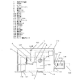
図1に示すように、この浴室サウナ装置1は外郭を形成する外装体2及びフロントパネル110、浴室内の空気を吸込み加熱加湿した後に再び浴室内に吹出すサウナモジュール111、外装体2の一面に設けられ、送風路と連通する開口部112に接続された換気ユニット113、またこれらを制御する制御装置114から構成されている。
As shown in FIG. 1, the
外装体2の浴室側一面を形成するフロントパネル110は、浴室内の空気を吸込むための吸込口102、加熱及び加湿した空気を外部に吹出すための吹出口101を備えている。また、吹出口101部には加熱加湿された空気の吹出方向を可変させるためのルーバー116が設けられており、ルーバー116は自在に稼動することで任意の方向に加熱加湿空気の吹出方向を可変させることができる。
The
フロントパネル110には、サウナ空間から空気を吸込む吸込口102および吹出口101を連結する送風路103が設けられており、送風路103の吸込口102側に備えられた温度センサー12が温度を計測し、設定温度に応じて制御装置114により回転数を自在に変更可能なモータ118に接続されたクロスフローファン4が回転することで吸込口102側からに吹出口101に空気を送風する。送風路103上のクロスフローファン4の下流側に加熱手段としての空気加熱用のヒーター3を備え、加熱手段としての空気加熱用のヒーター3の下流側には加湿部5が設けられている。クロスフローファン4により吸込口102から吸込まれた空気は、ヒーター3により加温され、高温の空気を加湿部5に送風することが可能となる。加湿部5に送風された高温の空気は、加湿部5に設けられた加湿手段としての給水経路124より給水の開閉手段である電磁弁125より温水を供給され噴出ノズル6から微細な水滴として噴霧し効率的に加湿する。噴霧加湿により、浴室内は、例えば、70〜100%RHに加湿される。
The
換気ユニット113は、浴室内空気を換気ユニット113に吸込むための換気用ファン128と空気の排気経路である排気ダクト129から構成されており、外装体2の一面に設けられた開口部112と開口部112の開口面積を可変させるためのダンパ130を介して接続している。ダンパ130は通常サウナ運転時には閉じられているが、制御装置114に接続されたダンパ駆動用モータ131により開閉可能であり、換気用ファン128を回転させるとともにダンパ130を開くことで浴室内空気を吸込口102より換気ユニット113内に通風し、排気ダクト129より吹出することで浴室内の換気を行う。
The
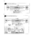
図2はコントローラーを示す外観図であり、図2(a)は洗面所用コントローラーの外観図であり、図2(b)は浴室用コントローラーの外観図である。洗面所に洗面所用コントローラー141を設け、浴室側に浴室用コントローラー142を設ける。洗面所用コントローラー141と浴室用コントローラー142には、うるおいモード用のうるおいモードスイッチ143を設け、浴室用コントローラー142には発汗センサー146を設けた構成となっている。このうるおいモードは、発汗センサー146により入浴者の汗状態を検知し、浴室サウナ装置の制御装置へ信号を送り、自動で発汗を抑えた温度に制御する。
FIG. 2 is an external view showing the controller, FIG. 2 (a) is an external view of a toilet controller, and FIG. 2 (b) is an external view of a bathroom controller. A
サウナ入浴では、入浴前にお湯をはるのと同様に、あらかじめ浴室内を一定の温度に上げてからサウナ入浴を行う。発汗センサー146による自動制御の場合、ある程度時間経過し、浴室内の温度が所定の値に達したら、例えば、サウナのうるおいモードでの初期の温度設定を約35℃とすると、浴室内が35℃になると入浴し、入浴後発汗センサー146で発汗をセンシングし、35℃に入浴者の体が馴染んだ状態で、発汗センサー146が発汗を検知すると温度設定を1℃下げて発汗が抑えられるとその温度を維持し、発汗量が抑えられない場合は更に温度設定を1℃下げ、発汗が抑えられる温度まで温度を下げてその温度を維持し、発汗がなくなると温度設定を1℃上げて発汗を検知すればその温度より1℃下げその温度を維持し、発汗を検知できなければ、さらに温度を1℃上げて、以降繰り返し行い、発汗する温度を検知し、その発汗する温度より1℃低い温度で維持する。ここでは、その発汗する温度より1℃低い温度で維持するとしたが、発汗を抑えて毛孔が広がる温度であればよく、例えば、発汗する温度より、0.1℃〜2℃程度低ければ良い。発汗する直前の温度程度が良い。発汗温湿度は個人差があるが、浴室内は、例えば、発汗直前の温度である35℃、相対湿度80%に保たれる。
In the sauna bathing, the bathing in the sauna is performed after raising the temperature in the bathroom to a certain temperature in the same way as hot water is poured before bathing. In the case of automatic control by the
こうすることで、発汗を抑えて毛孔を広げて浴室内の空気中から皮膚により多くの水分を吸収し皮膚に水分を浸透させて、皮膚、肌にうるおい効果をだし、発汗を抑えて発汗により汗とともに保湿成分が流れ出たり、あるいは発汗による汗をタオルで拭かれることにより保湿成分が拭き取られるなど、皮膚の保湿機構を妨げないようにすることができる。この発汗を抑えた状態とは、発汗して汗が流れ出ないようにする状況であり、すなわち汗が汗の出口である汗孔にたまり汗がにじむ程度であり、後に自然に蒸発するので汗をふき取ることがなく、保湿機構を妨げないものである。 By doing this, sweating is suppressed and the pores are expanded to absorb more moisture from the air in the bathroom and penetrate into the skin, so that the skin and skin have a moisturizing effect. It is possible to prevent the moisturizing mechanism of the skin from being disturbed, for example, the moisturizing component flows out with the sweat or the moisturizing component is wiped off by wiping the sweat caused by perspiration with a towel. This state where sweating is suppressed is a situation in which sweating prevents sweat from flowing out, i.e., the sweat accumulates in the sweat holes at the sweat outlet, and the sweat sweats. It does not wipe off and does not interfere with the moisturizing mechanism.
この発汗センサー146は、皮膚に貼り付け2点より微流な電流を流し皮膚の抵抗値の変化を計測する。発汗センサー146の貼り付けは汗が出るエクリン腺が全身にあるため汗をかくところのどこでも良いが、顔の保湿を目的とするため上半身に取り付ける方が良い。
The
また、手動設定のときは基準温度を35℃とし上下2℃ピッチで31℃から39℃まで5段階の温度調節ができるものとする。温度設定は、洗面所用コントローラー141では、うるおいモードスイッチ143を1秒以上押す事により温度表示145に1から5の5段表示の表示がされ手動で切り替え、浴室用コントローラー142では温度設定スイッチ144により温度表示145に表示された温度表示により設定温度を入浴者の入浴方法に応じて、手動で切り替えることができる。例えば短時間の入浴目的の時は39℃等の高めの温度で早く毛孔を開き発汗により汗を感じ始めたら化粧水で保湿しすぐに浴室から出たり、長時間リラックスしたいときは31℃等の低めの温度でゆっくり毛孔を開き発汗を抑えながらサウナ入浴を楽しむ事ができる。また、浴室用コントローラー142で浴室内で温度設定の切換が可能なので浴室から出る前にはもう少し体を温めるために1段階温度を上げるなどの使い方もできる。
In the manual setting, the reference temperature is set to 35 ° C., and the temperature can be adjusted in 5 steps from 31 ° C. to 39 ° C. at a pitch of 2 ° up and down. In the
図3は、この浴室サウナ装置内でうるおいモード中で洗浄効果試験によるマイクロスコープによる肌の計測であり、図3(a)は洗顔前の皮膚を示す図であり、図3(b)は入浴浴室で洗顔後の皮膚を示す図であり、図3(c)はうるおいモードで洗顔した洗顔後の皮膚を示す図である。図3(a)の洗顔前の状態と比べると、図3(b)の入浴浴室での洗顔後の状態では毛穴周辺やキメの皮溝にファンデーションのパールやラメなどの粉体が残り、すなわち洗顔前の化粧成分が残っており、皮膚表面は乾燥した感じでキメのふっくら感もなく、図3(c)のうるおいモードで洗顔した洗顔後の状態では肌を柔らかくし、毛穴が開き化粧成分の汚れが落ちており、また、お肌のキメは水分を含みふっくらし、細かなキメが見える。このようにうるおいモードでは、毛孔が開き汚れが落ちた上で肌が水分を吸収している状態が観測された。 FIG. 3 is a measurement of the skin by a microscope by a cleaning effect test in the moisture mode in this bathroom sauna apparatus, FIG. 3 (a) is a diagram showing the skin before face washing, and FIG. 3 (b) is a bathing. It is a figure which shows the skin after face-washing in a bathroom, FIG.3 (c) is a figure which shows the skin after face-washing washed in the moisture mode. Compared with the state before face washing in FIG. 3 (a), powders such as pearl and lame of the foundation remain in the vicinity of the pores and the skin crevice in the bathing bathroom in FIG. 3 (b), that is, and remain washing the face before of cosmetic ingredients, the skin surface is neither plump sense of texture feel, drying, softens the skin in the state after the cleansing was cleansing in moisture mode of FIG. 3 (c), opens the pores The makeup ingredients are clean, and the texture of the skin is moist and contains fine moisture. As described above, in the moisture mode, it was observed that the pores were opened and the dirt was removed and the skin was absorbing moisture.
図4は、化粧水塗布による保湿効果試験であり肌水分量を測定している。うるおいモード中に化粧水を塗布した場合とうるおいモード入浴後に化粧水を塗布した場合を比較したグラフであるが、うるおいモード中に化粧水を塗布した場合、浴室の温湿度環境が肌を柔らかくし毛孔を開き、ミストの微粒子が浸透しやすくなり、しかもミストは濡れにくく、発汗しにくいため化粧水を塗布しても流れることなく効果的であり、入浴中に化粧水を塗布すると入浴後の塗布と比較して肌の水分量は入浴45分後で1.4倍(有意差検定で有意差あり)水分量が多い状態が計測された。 FIG. 4 is a moisturizing effect test by applying lotion, and the skin moisture content is measured. It is a graph comparing the case of applying lotion during the moisture mode and the case of applying lotion after taking the bath in the moisture mode, but when the lotion is applied during the moisture mode, the temperature and humidity environment in the bathroom softens the skin. Opening the pores, making it easy for mist particles to permeate, and preventing mist from getting wet and sweating, so it is effective without applying even if lotion is applied. Compared with, the amount of moisture in the skin was 1.4 times after 45 minutes of bathing (significantly different in the significant difference test), and the state where the amount of moisture was high was measured.
図5は、図4の化粧水塗布による保湿効果試験時の診断評価であり、図5(a)は美容研究の専門家診断結果を示す図であり、図5(a)の美容研究の専門家診断結果により潤い感と総合評価で良い方向に優位差があり、図5(b)はモニター自己申告結果を示す図であり、図5(b)のモニター自己申告結果ではしっとり感においてよい方向に有意差があり、目的とする保湿効果が確認された。 FIG. 5 is a diagnostic evaluation at the time of the moisturizing effect test by applying the skin lotion of FIG. 4, FIG. 5 (a) is a diagram showing the results of expert diagnosis of beauty research, and the specialty of beauty research of FIG. There is a difference in the direction of goodness in moist feeling and comprehensive evaluation depending on the house diagnosis result, FIG. 5 (b) is a diagram showing the monitor self-report result, and the monitor self-report result in FIG. The target moisturizing effect was confirmed.
図6は、うるおいモード中での美容目的のフェイスエステのコースを示す図であり、図6(a)はうるおいモードの中で肌や髪のケアのための標準コースを示す図であり、図6(b)はオプションコースを示す図であり、図6(a)のうるおいモードの中で肌や髪のケアのための標準コースや図6(b)のオプションコースのように美容のための肌のケアコースを行うことができ、より効果的に肌の保湿ケアを行う事ができる。更に同時にマッサージなどの血行を良くする行為を行い美しい肌を保つ美容行為を行うことができる。 FIG. 6 is a diagram showing a course of a beauty treatment face esthetic in the moisture mode, and FIG. 6A is a diagram showing a standard course for skin and hair care in the moisture mode. 6 (b) is a diagram showing an optional course. In the moisture mode of FIG. 6 (a), the standard course for skin and hair care and the optional course of FIG. A skin care course can be performed, and skin moisturizing care can be performed more effectively. At the same time, it is possible to perform an act of improving blood circulation such as massage, and a beauty act of maintaining beautiful skin.
図7は浴室内状況を示す図であり、図7(a)は読書を示す図であり、図7(b)はテレビ鑑賞を示す図であり、図7(a)の読書と図7(b)のテレビ鑑賞の浴室内状況を示したものであるが、濡れにくく見えないミストによりよく室内で読書やテレビ鑑賞ができ、その時間を利用して水分の吸収を高め、化粧水を塗布して肌の保湿効果を高めるミスト中の肌のケアをことができる。 FIG. 7 is a diagram showing the situation in the bathroom, FIG. 7 (a) is a diagram showing reading, FIG. 7 (b) is a diagram showing watching TV, and the reading of FIG. 7 (a) and FIG. Although Ru der shows the bathroom within the context of the television viewing of b), well you are reading or watch TV in the room by mist invisible difficult to wet, increase the absorption of moisture by utilizing the time, applying the lotion And can care for the skin in the mist that enhances the moisturizing effect of the skin.
図8は、入浴スタイルへの対応図であり、図に示すように個人の入浴スタイルに応じてうるおいモードと、発汗を目的としたサウナモードを選択できサウナ浴を楽しむ事が出来る。特にうるおいモードは体への負担も少なく多くの入浴スタイルに対応できる。 FIG. 8 is a diagram corresponding to the bathing style. As shown in the figure, the moisture mode and the sauna mode for sweating can be selected according to the individual bathing style, and the sauna bath can be enjoyed. In particular, the moisture mode is less burdensome on the body and can accommodate many bathing styles.
図9に示すように外装体2の浴室側一面を形成するフロントパネル110は、浴室内の空気を吸込むための吸込口102、加熱及び加湿した空気を外部に吹出すための吹出口101を備えている。また、吸込口102に吸込口102を通過する空気の温度を測定する温度センサー12を備え、また、吸込口102の装置内部側にはフィルター115を備えており、浴室内空気を循環させる際に微細な塵や埃の侵入を防止する構造となっている。また、吹出口101部には加熱加湿された空気の吹出方向を可変させるためのルーバー116が設けられており、ルーバー116はルーバー駆動モータ117により自在に稼動することで任意の方向に吹出方向を可変させることができる。
As shown in FIG. 9, the
図10に示すようにフロントパネル110の吸込口102および吹出口101を連結する送風路103が設けられており、送風路103の吸込口102側に備えられた、制御装置114により回転数を自在に変更可能なモータ118に接続されたクロスフローファン4が回転することで吸込口102側からに吹出口101に空気を送風する。クロスフローファン4の下流側には、加熱手段としての空気加熱用のヒーター3を備えており、このヒーター3により空気が加温され、高温の空気を送風することが可能となる。送風路103内の送風機としてのクロスフローファン4の下流側には加湿部5が設けられている。加湿部5に設けられた加湿手段としての噴出ノズル6に温水を供給し、供給された温水を噴出ノズル6から微細な水滴として噴霧する。
As shown in FIG. 10, an
この時、噴霧方向前方に噴霧水滴破砕手段7を設け、噴霧された水滴を噴霧水滴破砕手段7を用いてさらに微細な形状へと変化させる。ここで微細な水滴(例えば水滴径100μm以下)に関しては送風する空気とともに吹出口101に運ばれ浴室内を加湿し、微細な水滴に破砕することができなかった水滴に関しては、排水部120へと向かう。送風空気とともに運ばれる微細な水滴の中でも、比較的水滴径が大なる水滴(例えば水滴径10〜100μm)に関しては加湿部5の吹出口101側に設けられたエリミネータ8で回収され、排水部120へと向かう。エリミネータ8を通過した微細な水滴(水滴径10μm以下)はヒーター3により加熱された空気とともに吹出口101より浴室に供給され、浴室内を加熱加湿する。エリミネータ8は粗いメッシュ状の素材を複数枚積層して構成されており、従来の通気案内板を用いた蛇行風路のような大掛かりな構成を必要とせず、且つ圧力損失も比較的小さくできる。ここで噴霧水滴破砕手段7は噴出ノズル6から噴霧された水滴を更に微細な水滴に破砕できればよく、例えば、噴出ノズル6に対して設けられた衝突板、回転板、あるいは、表面がぎざぎざ形状の板などがある。この噴霧水滴破砕手段7により絶対湿度0.011kg/kg´以上の空気を送ることにより、加熱加湿対象室内の壁面に発生する結露より多く加湿することができ、更に加熱加湿対象室内の空気がミスト装置を循環しながら絶対湿度0.011kg/kg´以上の空気を送り続ける事により累積して、加熱加湿対象室内を湿度80%以上まで高めることができる。
At this time, the sprayed water droplet crushing means 7 is provided in front of the spraying direction, and the sprayed water droplet is changed into a finer shape using the sprayed water droplet crushing means 7. Here, with respect to fine water droplets (for example, a water droplet diameter of 100 μm or less), the water droplets that are carried along with the air to be blown to the
例えば、図11の空気線図にあるように、1坪の浴室内において浴室初期温度であるポイント1)151を20℃60%とし、絶対湿度0.011kg/kg´の空気であるポイント2)152を吹出すとポイント1)151の空気とポイント2)152の空気が混じりあいポイント3)153に到達するはずであるが、実際は浴室の壁面結露156によりポイント2)152の空気がポイント4)154に下がり、ポイント4)154とポイント1)151の空気が混じりあいポイント5)155になる。これを繰り返すことによりライン1)157の軌跡で累積し、加熱加湿対象室内の湿度を絶対湿度0.029kg/kg´以上にすることが可能となる。但し、絶対湿度0.011kg/kg´以下の空気を送ると浴室内の湿度上昇に時間がかかり、更に、壁面結露156によりポイント4)154が絶対湿度0.099kg/kg´以下になると加湿されなくなるため絶対湿度0.011kg/kg´以上の空気を送る必要がある。
For example, as shown in the air diagram of FIG. 11, point 1) which is the initial temperature of the bathroom in a 1 tsubo bathroom, point 2) which is air at an absolute humidity of 0.011 kg / kg ′, with 151 being 20 ° C. and 60%. When the air is blown out, the air at point 1) 151 and the air at point 2) 152 are mixed and should reach point 3) 153, but in reality, the air at point 2) 152 is at point 4) due to
排水部120に向かった水分は排水部120に連結されている排水管122を通り装置外部に排水される。排水部120は加湿部5の最下部に設けられるとともに、底面に排水管接続部が最下端となるように勾配を持たせており、加湿部内に余剰水を滞留させないようにしてある。この際、底面の排水勾配は角度が大きければ大きいほど良いが、望ましくは5°以上の勾配を確保することによって、加湿部内の余剰水を確実に排水することが可能となる。これと同様に、装置外部に接続される排水管も同等の5°以上の勾配を確保して設置することで装置内への余剰水の滞留を防止することができる。また、排水部120にはフロートスイッチ123を備えており、排水部120の水位上昇を検知し、所定の水位を超えた場合には制御装置114が噴出ノズル6への給水を停止することで加湿部5からの漏水を防止する。
Moisture directed toward the drainage part 120 passes through a
給水経路124上には電磁弁125を設け、給水を開閉制御することで加湿水の供給量を変更可能にする。電磁弁125とは電気信号により電磁力を利用した弁が開閉する方式の弁である。
An
図12に示すようにヒーター3の下流で加湿部5の上流の位置には加湿部5から飛散する水滴がヒーター3に付着するのを防止するために飛散防止をする水滴飛散防止板9が設けられている。水滴飛散防止板9は空気の流通方向に対して傾斜した角度で設置されており、傾斜させることにより空気の流通への影響を極力小さくしながら水滴の飛散を防止することが可能となる。
As shown in FIG. 12, at the position downstream of the
図13に示すように、ヒーター3はセラミックなどの発熱体10に空気との伝熱性を促進するための伝熱用フィン11が取り付けられた構造となっており、発熱体10に通電することで発熱体10が発熱し、伝熱用フィン11を昇温し、昇温された伝熱用フィン11周辺を空気が流通することで流通する空気を加熱昇温する。発熱体10及び伝熱用フィン11の表面は電気的に絶縁されており、水滴等の付着が生じた場合でも漏電等の障害は生じない構造となっている。
As shown in FIG. 13, the
図14に示す換気ユニット113は、浴室内空気を換気ユニット113に吸込むための換気用ファン128と空気の排気経路である排気ダクト129から構成されており、外装体2の一面に設けられた開口部112と開口部112の開口面積を可変させるためのダンパ130を介して接続している。ダンパ130は通常サウナ運転時には閉じられているが、制御装置114に接続されたダンパ駆動用モータ131により開閉可能であり、換気用ファン128を回転させるとともにダンパ130を開くことで浴室内空気を吸込口102より換気ユニット113内に通風し、排気ダクト129より吹出することで浴室内の換気を行う。換気量の調整はダンパ130の開口面積の変更及び換気用ファン128の回転数制御により行い、これらの組み合わせにより必要とする換気量を実現する。
A
次に浴室サウナ装置1の制御装置114の詳細を、図1をもとに示す。
Next, the detail of the
サウナ運転を開始すると、サウナモジュール111内のモータ118が作動することでクロスフローファン4が回転し、吸込口102より浴室内の空気を吸入し、送風路103を通り吹出口101から再び浴室内に流出することで浴室内空気を循環する。その時、空気加熱用のヒーター3および給水経路124の開閉手段である電磁弁125に通電し空気の加熱及び加湿部5の噴出ノズル6へ加湿水の供給を開始することで装置内において浴室内空気の加熱及び加湿が開始される。この際、フロントパネル110に設けてあるルーバー116が開放し、加熱加湿された空気の吹出方向を制御する。
When the sauna operation is started, the
ある程度時間経過し、浴室内の温湿度が所定の値に達したら、例えば、サウナのうるおいモードでの温度設定を約35℃とすると、その温度より若干低い温度で温調を開始する意味で、所定温湿度の約34℃、80%RHに達すると、モータ118の回転数を変更し、加熱及び加湿量を変更する。その後、更にある程度時間経過し、例えば、5分程度経過し、浴室内の温湿度が所定の値を超えたら、例えばうるおいモードでの温度設定が35℃なので、その温度より若干高温にすることにより温調の幅を持たせる意味で、の浴室内の温湿度の約36℃、80%RH程度に達すると、浴室内の温湿度を調節するためにモータ118の回転数及びヒーターへの通電量を変更し、給水経路124に設けられた電磁弁125の開閉を繰り返すことで浴室内の温湿度の制御を行う。ここで、本実施の形態1では、温度センサー12で、温度を計測して、相対湿度を推定したが、もちろん、温度センサーと湿度センサーの両方を用いて、温度、湿度を計測しても良い。
When the temperature and humidity in the bathroom reach a predetermined value after a certain period of time, for example, if the temperature setting in the moisture mode of the sauna is about 35 ° C., the temperature adjustment starts at a temperature slightly lower than that temperature, When the predetermined temperature and humidity of about 34 ° C. and 80% RH are reached, the number of revolutions of the
サウナ運転停止時には、サウナモジュール111内モータ118の運転を停止し、給水経路124に設けられた電磁弁125を閉じる。その後、浴室内の乾燥のために換気運転を行うため、外装体2と換気ユニット113の連結部に設けられたダンパ130はダンパ駆動用モータ131により開き、換気ユニット113内の換気用ファン128を回転させることで浴室サウナ装置1の吸込口102より流入した浴室内空気を排気ダクト129より浴室外へと排出する。
When the sauna operation is stopped, the operation of the
前述したような動作を実施することでサウナ対象室(浴室)内は高温高湿(35℃/80%程度)の状態となり、また、本実施の形態の様な構成で加湿部5を形成することにより、従来の蛇行風路の様な大掛かりな構成を組まなくとも、送風路103内で大径な水滴は回収し、比較的小径な水滴のみを浴室内に吹出すことが可能となる。
By performing the operation as described above, the sauna target room (bathroom) is in a high-temperature and high-humidity state (about 35 ° C./80%), and the
上記のような運転を行うことにより、浴室内を所定の温湿度に上昇させ、サウナ空間とすることが可能となる。また、本実施の形態で記載した構造とすることでより多くの加湿量を得ることができ、絶対湿度の高い温かい空気により毛孔が広がった皮膚にサウナ空間からより多くの水分を吸収し、浸透し、発汗を抑えた温度により皮膚の保湿機構を妨げない浴室サウナ装置を提供することができる。 By performing the operation as described above, the interior of the bathroom is raised to a predetermined temperature and humidity, and a sauna space can be formed. In addition, the structure described in the present embodiment can obtain a larger amount of humidification, absorbs more moisture from the sauna space into the skin where pores have spread by warm air with high absolute humidity, and permeates. Thus, it is possible to provide a bathroom sauna apparatus that does not interfere with the moisture retention mechanism of the skin due to the temperature at which sweating is suppressed.
なお、本実施の形態においてはサウナ対象室を浴室として説明をしたが、高湿度空間になった場合の結露等の問題を解決できるのであれば浴室に限定するものではなく、サウナ専用の空間を別途設ける構成としてもその作用効果に差異を生じない。 In this embodiment, the sauna target room has been described as a bathroom. However, if the problem such as condensation in a high humidity space can be solved, the room is not limited to the bathroom, and a space dedicated to the sauna is used. Even if the configuration is provided separately, there is no difference in the function and effect.
また、本実施の形態においては送風空気を加温する手段としてセラミックの発熱体を用いたヒーターを用いたが、送風空気を充分に加温できるのであれば他の加温手段を用いても全く問題は無く、シーズヒーターやニクロムヒーター、温水又は冷媒を流す熱交換器、その他の熱源体を用いても、その作用効果に差異を生じない。 In this embodiment, a heater using a ceramic heating element is used as means for heating the blown air. However, other heating means may be used as long as the blown air can be sufficiently heated. There is no problem, and even if a sheathed heater, nichrome heater, heat exchanger for flowing hot water or refrigerant, or other heat source is used, there is no difference in the effect.
また、本実施の形態においては加湿部5において温水を噴霧することにより加湿を行う構成としたが、浴室が狭小(0.5坪程度)でそれほど大量な加湿を必要としない場合においては通常温度(20℃程度)の水道水などを使用してもその作用効果に差異を生じず、望ましくは浴室の広さや浴室外の温度雰囲気等に応じて浴室内が目的の温湿度となるように噴出ノズル6より噴出する加湿水の温度を適宜設定することが望ましい。さらには加湿水を噴霧する方法だけでなく、超音波発振子などを用いて空気中に微細な水滴を拡散させる方式、加熱により気化した加湿水を供給することで加湿する方式、をとってもよくその作用効果に差異を生じない。
Moreover, in this Embodiment, it was set as the structure which humidifies by spraying warm water in the
また、本実施の形態において噴霧水滴破砕手段7は特に説明はしなかったが噴霧後の微細水滴をさらに細かく破砕するための手段であり、噴出ノズル6から噴霧された推進力を持った微細な水滴を回転体や形状を凸凹にした壁面、また材質を考慮した壁面に水滴を噴霧する方法により水滴を細かく破砕する手段であれば良く、その形状や材質等を限定するものではない。なお望ましくは、噴霧水破砕手段への水滴の衝突時に相対速度が極力大きくなり、なおかつ多方向に反射するような形状を取ることによってより細かい水滴に破砕することが可能になる。
In the present embodiment, the sprayed water droplet crushing means 7 is not particularly described, but is a means for further finely crushing the fine water droplets after spraying, and has a fine force with propulsive force sprayed from the
また、本実施例においてはエリミネータ8を通過する水滴径を10μm以下としたが、水滴径100μm以下の水滴径であればよく、エリミネータ8を通過し、浴室内に供給される水滴径は入浴者が水滴感を感じることなく入浴できる程度の水滴径であることが望ましく、一般的には10μm以下程度の水滴径とすることでほとんどの人が水滴感を感じることなく入浴を行うことができる。さらに、化粧水を塗布しても加湿により濡れると効果がなくなるため、濡れない粒径にすることにより化粧水塗布による水分量保持効果が持続でき、不快感がないため肌をタオルなどでふき取る必要がないので肌の保湿を保つ皮脂などの皮膚を剥ぎ取ることがない。 Further, in this embodiment, the diameter of the water droplet passing through the eliminator 8 is 10 μm or less, but the water droplet diameter may be any water droplet diameter of 100 μm or less, and the water droplet diameter passing through the eliminator 8 and supplied into the bathroom is the bather. It is desirable that the diameter of the water droplet is such that it can be bathed without feeling a water droplet. Generally, by setting the water droplet diameter to about 10 μm or less, most people can take a bath without feeling the water droplet. In addition, even if lotion is applied, it loses its effect when it is moistened. Therefore, it is necessary to wipe off the skin with a towel etc. Since there is no skin, the skin such as sebum that keeps the skin moisturized will not be peeled off.
また、本実施の形態においては液体供給手段として、上水道をそのまま配管で連結して用いているが、水圧の増大を図りたい場合にはポンプ等により圧力を高めて供給しても問題なく、その作用効果に差異を生じない。 Further, in the present embodiment, the water supply is directly connected to the pipe as the liquid supply means. However, if it is desired to increase the water pressure, there is no problem even if the pressure is increased by a pump or the like. There is no difference in function and effect.
また、本実施の形態においては給水経路124の開閉手段として電磁弁125を用いたが、何らかの制御手段を用いて回路を開閉できるのであれば他の手段を用いても全く問題は無く、熱動弁等を用いてもその作用効果に差異を生じない。なお望ましくは制御装置114による温湿度の制御が可能な流量調節弁であり且つ制御信号に対する応答性の良いものが好ましい。
In the present embodiment, the
また、本実施形態においては、うるおいモードのコントロールの基準温度を35℃とし上下2℃ピッチで31℃から39℃までの5段階調節にしているが、個人への適用性や使用性により1℃で10段階調節にしても良い。 In the present embodiment, the reference temperature for moisture mode control is 35 ° C., and is adjusted in 5 steps from 31 ° C. to 39 ° C. at a pitch of 2 ° up and down, but it is 1 ° C. depending on applicability and usability to individuals. It may be adjusted in 10 steps.
加熱加湿対象室に取り付けた加熱加湿装置を用いて高い湿度状態で温度条件の設定が容易になり、寝室などの一般住宅の居室から浴室をサウナ空間にするためのサウナ装置としての用途にも適用できる。また、大加湿量を得ることが可能なため、大型のサウナ施設などの大空間に適用することも可能である。 Using a heating / humidifying device attached to the room to be heated / humidified makes it easy to set the temperature conditions in a high humidity state, and it can also be used as a sauna device to convert the bathroom from a living room in a general house such as a bedroom into a sauna space. it can. In addition, since a large amount of humidification can be obtained, the present invention can be applied to a large space such as a large sauna facility.
1 浴室サウナ装置
2 外装体
3 ヒーター
4 クロスフローファン
5 加湿部
6 噴出ノズル
7 噴霧水滴破砕手段
8 エリミネータ
9 水滴飛散防止板
10 発熱体
11 伝熱用フィン
12 温度センサー
101 吹出口
102 吸込口
103 送風路
104 本体
105 気液接触部
106 熱水供給部材
107 空気供給部材
108 加熱部材
109 サウナ装置
110 フロントパネル
111 サウナモジュール
112 開口部
113 換気ユニット
114 制御装置
115 フィルター
116 ルーバー
117 ルーバー駆動モータ
118 モータ
120 排水部
122 排水管
123 フロートスイッチ
124 給水経路
125 電磁弁
128 換気用ファン
129 排気ダクト
130 ダンパ
131 ダンパ駆動用モータ
141 洗面所用コントローラー
142 浴室用コントローラー
143 うるおいモードスイッチ
144 温度設定スイッチ
145 温度表示
146 発汗センサー
151 ポイント1)
152 ポイント2)
153 ポイント3)
154 ポイント4)
155 ポイント5)
156 壁面結露
157 ライン1)
DESCRIPTION OF
152 points 2)
153 points 3)
154 points 4)
155 points 5)
156
Claims (13)
Priority Applications (4)
| Application Number | Priority Date | Filing Date | Title |
|---|---|---|---|
| JP2006287284A JP5092346B2 (en) | 2006-10-23 | 2006-10-23 | Sauna device that suppresses sweating and widens pores |
| PCT/JP2007/070587 WO2008050735A1 (en) | 2006-10-23 | 2007-10-23 | Bathroom sauna device |
| US12/446,623 US8132795B2 (en) | 2006-10-23 | 2007-10-23 | Bathroom sauna device |
| US13/365,316 US8602398B2 (en) | 2006-10-23 | 2012-02-03 | Bathroom sauna device |
Applications Claiming Priority (1)
| Application Number | Priority Date | Filing Date | Title |
|---|---|---|---|
| JP2006287284A JP5092346B2 (en) | 2006-10-23 | 2006-10-23 | Sauna device that suppresses sweating and widens pores |
Publications (3)
| Publication Number | Publication Date |
|---|---|
| JP2008104482A JP2008104482A (en) | 2008-05-08 |
| JP2008104482A5 JP2008104482A5 (en) | 2009-12-03 |
| JP5092346B2 true JP5092346B2 (en) | 2012-12-05 |
Family
ID=39324532
Family Applications (1)
| Application Number | Title | Priority Date | Filing Date |
|---|---|---|---|
| JP2006287284A Active JP5092346B2 (en) | 2006-10-23 | 2006-10-23 | Sauna device that suppresses sweating and widens pores |
Country Status (3)
| Country | Link |
|---|---|
| US (2) | US8132795B2 (en) |
| JP (1) | JP5092346B2 (en) |
| WO (1) | WO2008050735A1 (en) |
Families Citing this family (14)
| Publication number | Priority date | Publication date | Assignee | Title |
|---|---|---|---|---|
| FR2927237B1 (en) * | 2008-02-13 | 2011-12-23 | Oreal | DEVICE FOR SPRAYING A COSMETIC PRODUCT WITH HOT OR COLD AIR BLOWING |
| US8676044B2 (en) | 2008-03-19 | 2014-03-18 | Sunlighten, Inc. | Dynamic sauna |
| CN103565626B (en) * | 2012-07-30 | 2017-09-22 | 广东松下环境系统有限公司 | Micro- mist sauna apparatus |
| CN103655154B (en) * | 2012-09-14 | 2017-09-15 | 广东松下环境系统有限公司 | Micro- mist sauna apparatus |
| CN103655153B (en) * | 2012-09-14 | 2017-08-08 | 广东松下环境系统有限公司 | Micro- mist sauna apparatus |
| US9815557B2 (en) * | 2012-09-20 | 2017-11-14 | Humbay Health, LLC | Aircraft humidifier |
| US9889270B2 (en) * | 2012-09-28 | 2018-02-13 | Panasonic Intellectual Property Management Co., Ltd. | Method of controlling relaxation equipment, control system for relaxation equipment, and method of creating user model |
| CN105456017A (en) * | 2014-09-01 | 2016-04-06 | 青岛海尔智能技术研发有限公司 | Household sauna machine and sauna mist generating method |
| US10616955B1 (en) | 2016-02-23 | 2020-04-07 | Sunlighten, Inc. | Personal sauna unit with integrated chromotherapy lighting |
| JP2017164380A (en) * | 2016-03-17 | 2017-09-21 | 大阪瓦斯株式会社 | Mist device directly connected to hot water supply system |
| JP2017164381A (en) * | 2016-03-17 | 2017-09-21 | 大阪瓦斯株式会社 | Mist device directly connected to hot water supply system |
| FI126907B (en) * | 2016-05-25 | 2017-07-31 | Risto Tapio Yli-Kovero | A method for controlling a sauna with a fan, a controller for controlling the sauna stove and a sauna heater |
| AU2019308154A1 (en) | 2018-07-06 | 2021-01-28 | Sunlighten, Llc | Personal portable therapy chamber |
| US11913460B2 (en) | 2020-03-20 | 2024-02-27 | Greenheck Fan Corporation | Exhaust fan |
Family Cites Families (21)
| Publication number | Priority date | Publication date | Assignee | Title |
|---|---|---|---|---|
| US3105892A (en) * | 1960-06-06 | 1963-10-01 | Knapp Monarch Co | Humidifier heater |
| US3869529A (en) * | 1972-08-30 | 1975-03-04 | Donald T Follette | Air conditioning apparatus |
| US4003967A (en) * | 1974-10-31 | 1977-01-18 | Les Placement Courteau Limitee | Electric heating and humidifying apparatus |
| JPS6328879Y2 (en) * | 1980-03-27 | 1988-08-03 | ||
| US4711294A (en) * | 1985-08-14 | 1987-12-08 | Jacobs Alphonse F | Temperature and humidity control system |
| GB2195434B (en) * | 1986-09-18 | 1991-01-16 | Wellmen Ind Co Ltd | A combined humidifier and fan heater unit |
| JPS63238864A (en) | 1987-03-26 | 1988-10-04 | 株式会社イナックス | Steam sauna |
| JPH0629540A (en) | 1990-08-15 | 1994-02-04 | Intel Corp | Method for formation of floating gate member of nonvolatile memory cell and floating gate member |
| US5350117A (en) * | 1992-01-31 | 1994-09-27 | Itamar Kleinberger | Discriminating humidification system |
| JPH0629540U (en) * | 1992-09-30 | 1994-04-19 | 三井鉱山株式会社 | Steam generator |
| JPH06327741A (en) * | 1993-05-26 | 1994-11-29 | Robuitsuku:Kk | Perspiration action accelerating device |
| JP3532646B2 (en) | 1995-02-17 | 2004-05-31 | 三井鉱山株式会社 | Steam generator |
| US5651498A (en) * | 1995-07-21 | 1997-07-29 | Honeywell Inc. | Heating system with humidity control for avoiding water condensation on interior window surfaces |
| US5702648A (en) * | 1996-02-16 | 1997-12-30 | Morgan & White Ltd., Pa Corp. | Self-contained room air humidifier |
| US6092794A (en) * | 1998-12-23 | 2000-07-25 | Cool Fog Systems, Inc. | Secondary air humidification handler |
| JP2004089866A (en) * | 2002-08-30 | 2004-03-25 | Denso Corp | Method and apparatus for producing fine particle |
| JP4653394B2 (en) * | 2003-09-19 | 2011-03-16 | 有限会社東北ティック | Hot bath facility and temperature / humidity control method thereof |
| JP2005278782A (en) * | 2004-03-29 | 2005-10-13 | Matsushita Electric Ind Co Ltd | Bathroom sauna apparatus |
| JP2006136651A (en) * | 2004-11-15 | 2006-06-01 | Osaka Gas Co Ltd | Mist sauna device |
| JP4475132B2 (en) * | 2005-02-04 | 2010-06-09 | パナソニック株式会社 | Sauna equipment |
| US7896319B2 (en) * | 2006-12-28 | 2011-03-01 | Panasonic Corporation | Sauna apparatus |
-
2006
- 2006-10-23 JP JP2006287284A patent/JP5092346B2/en active Active
-
2007
- 2007-10-23 WO PCT/JP2007/070587 patent/WO2008050735A1/en active Application Filing
- 2007-10-23 US US12/446,623 patent/US8132795B2/en active Active
-
2012
- 2012-02-03 US US13/365,316 patent/US8602398B2/en active Active
Also Published As
| Publication number | Publication date |
|---|---|
| WO2008050735A1 (en) | 2008-05-02 |
| US20120131743A1 (en) | 2012-05-31 |
| US8602398B2 (en) | 2013-12-10 |
| JP2008104482A (en) | 2008-05-08 |
| US8132795B2 (en) | 2012-03-13 |
| US20100024118A1 (en) | 2010-02-04 |
Similar Documents
| Publication | Publication Date | Title |
|---|---|---|
| JP5092346B2 (en) | Sauna device that suppresses sweating and widens pores | |
| JP4670442B2 (en) | Sauna equipment | |
| JP2007275453A (en) | Sauna system | |
| JP4967764B2 (en) | Sauna equipment | |
| JP2008082570A (en) | Heating humidifying device | |
| JPH05317377A (en) | Sauna unit | |
| JP4910352B2 (en) | Sauna equipment | |
| KR20120083156A (en) | Electric fan | |
| JP4480221B2 (en) | Mist sauna equipment | |
| JP4481381B2 (en) | Sauna equipment and its operation method and bathroom ventilation heating dryer | |
| JP4878578B2 (en) | Bathroom heater with mist sauna function | |
| JP4367047B2 (en) | Sauna method and sauna apparatus | |
| JP2006025963A (en) | Bathroom sauna device | |
| JP3252079B2 (en) | Steam sauna equipment | |
| JP2009030943A (en) | Bathroom air conditioning device | |
| JP5126348B2 (en) | Sauna equipment | |
| JP5034413B2 (en) | Sauna equipment | |
| JP4593527B2 (en) | Bathroom heater with mist sauna function | |
| JP2008104483A (en) | Mist sauna apparatus | |
| JP2009082391A (en) | Bathroom mist sauna device | |
| KR200374120Y1 (en) | Humidifier | |
| JP2009030836A (en) | Bathroom air conditioning device | |
| JP2008295894A (en) | Mist sauna apparatus for bathroom | |
| JP2008295890A (en) | Bathroom mist sauna apparatus | |
| JP2008237479A (en) | Bathroom mist sauna apparatus |
Legal Events
| Date | Code | Title | Description |
|---|---|---|---|
| A521 | Written amendment |
Free format text: JAPANESE INTERMEDIATE CODE: A523 Effective date: 20091019 |
|
| A621 | Written request for application examination |
Free format text: JAPANESE INTERMEDIATE CODE: A621 Effective date: 20091019 |
|
| RD01 | Notification of change of attorney |
Free format text: JAPANESE INTERMEDIATE CODE: A7421 Effective date: 20091112 |
|
| A131 | Notification of reasons for refusal |
Free format text: JAPANESE INTERMEDIATE CODE: A131 Effective date: 20110726 |
|
| A521 | Written amendment |
Free format text: JAPANESE INTERMEDIATE CODE: A523 Effective date: 20110926 |
|
| A131 | Notification of reasons for refusal |
Free format text: JAPANESE INTERMEDIATE CODE: A131 Effective date: 20120327 |
|
| A521 | Written amendment |
Free format text: JAPANESE INTERMEDIATE CODE: A523 Effective date: 20120515 |
|
| TRDD | Decision of grant or rejection written | ||
| A01 | Written decision to grant a patent or to grant a registration (utility model) |
Free format text: JAPANESE INTERMEDIATE CODE: A01 Effective date: 20120821 |
|
| A01 | Written decision to grant a patent or to grant a registration (utility model) |
Free format text: JAPANESE INTERMEDIATE CODE: A01 |
|
| A61 | First payment of annual fees (during grant procedure) |
Free format text: JAPANESE INTERMEDIATE CODE: A61 Effective date: 20120903 |
|
| R151 | Written notification of patent or utility model registration |
Ref document number: 5092346 Country of ref document: JP Free format text: JAPANESE INTERMEDIATE CODE: R151 |
|
| FPAY | Renewal fee payment (event date is renewal date of database) |
Free format text: PAYMENT UNTIL: 20150928 Year of fee payment: 3 |