JP5089841B2 - Optical system for projection display - Google Patents
Optical system for projection display Download PDFInfo
- Publication number
- JP5089841B2 JP5089841B2 JP2001507143A JP2001507143A JP5089841B2 JP 5089841 B2 JP5089841 B2 JP 5089841B2 JP 2001507143 A JP2001507143 A JP 2001507143A JP 2001507143 A JP2001507143 A JP 2001507143A JP 5089841 B2 JP5089841 B2 JP 5089841B2
- Authority
- JP
- Japan
- Prior art keywords
- light
- reflected
- exit
- lens
- prism
- Prior art date
- Legal status (The legal status is an assumption and is not a legal conclusion. Google has not performed a legal analysis and makes no representation as to the accuracy of the status listed.)
- Expired - Lifetime
Links
Images

Classifications
-
- G—PHYSICS
- G03—PHOTOGRAPHY; CINEMATOGRAPHY; ANALOGOUS TECHNIQUES USING WAVES OTHER THAN OPTICAL WAVES; ELECTROGRAPHY; HOLOGRAPHY
- G03B—APPARATUS OR ARRANGEMENTS FOR TAKING PHOTOGRAPHS OR FOR PROJECTING OR VIEWING THEM; APPARATUS OR ARRANGEMENTS EMPLOYING ANALOGOUS TECHNIQUES USING WAVES OTHER THAN OPTICAL WAVES; ACCESSORIES THEREFOR
- G03B21/00—Projectors or projection-type viewers; Accessories therefor
- G03B21/14—Details
- G03B21/142—Adjusting of projection optics
-
- H—ELECTRICITY
- H04—ELECTRIC COMMUNICATION TECHNIQUE
- H04N—PICTORIAL COMMUNICATION, e.g. TELEVISION
- H04N9/00—Details of colour television systems
- H04N9/12—Picture reproducers
- H04N9/31—Projection devices for colour picture display, e.g. using electronic spatial light modulators [ESLM]
- H04N9/3141—Constructional details thereof
-
- G—PHYSICS
- G02—OPTICS
- G02B—OPTICAL ELEMENTS, SYSTEMS OR APPARATUS
- G02B26/00—Optical devices or arrangements for the control of light using movable or deformable optical elements
- G02B26/08—Optical devices or arrangements for the control of light using movable or deformable optical elements for controlling the direction of light
- G02B26/0816—Optical devices or arrangements for the control of light using movable or deformable optical elements for controlling the direction of light by means of one or more reflecting elements
- G02B26/0833—Optical devices or arrangements for the control of light using movable or deformable optical elements for controlling the direction of light by means of one or more reflecting elements the reflecting element being a micromechanical device, e.g. a MEMS mirror, DMD
-
- G—PHYSICS
- G02—OPTICS
- G02B—OPTICAL ELEMENTS, SYSTEMS OR APPARATUS
- G02B26/00—Optical devices or arrangements for the control of light using movable or deformable optical elements
- G02B26/08—Optical devices or arrangements for the control of light using movable or deformable optical elements for controlling the direction of light
- G02B26/0875—Optical devices or arrangements for the control of light using movable or deformable optical elements for controlling the direction of light by means of one or more refracting elements
- G02B26/0883—Optical devices or arrangements for the control of light using movable or deformable optical elements for controlling the direction of light by means of one or more refracting elements the refracting element being a prism
-
- G—PHYSICS
- G03—PHOTOGRAPHY; CINEMATOGRAPHY; ANALOGOUS TECHNIQUES USING WAVES OTHER THAN OPTICAL WAVES; ELECTROGRAPHY; HOLOGRAPHY
- G03B—APPARATUS OR ARRANGEMENTS FOR TAKING PHOTOGRAPHS OR FOR PROJECTING OR VIEWING THEM; APPARATUS OR ARRANGEMENTS EMPLOYING ANALOGOUS TECHNIQUES USING WAVES OTHER THAN OPTICAL WAVES; ACCESSORIES THEREFOR
- G03B21/00—Projectors or projection-type viewers; Accessories therefor
- G03B21/005—Projectors using an electronic spatial light modulator but not peculiar thereto
-
- G—PHYSICS
- G03—PHOTOGRAPHY; CINEMATOGRAPHY; ANALOGOUS TECHNIQUES USING WAVES OTHER THAN OPTICAL WAVES; ELECTROGRAPHY; HOLOGRAPHY
- G03B—APPARATUS OR ARRANGEMENTS FOR TAKING PHOTOGRAPHS OR FOR PROJECTING OR VIEWING THEM; APPARATUS OR ARRANGEMENTS EMPLOYING ANALOGOUS TECHNIQUES USING WAVES OTHER THAN OPTICAL WAVES; ACCESSORIES THEREFOR
- G03B21/00—Projectors or projection-type viewers; Accessories therefor
- G03B21/14—Details
- G03B21/20—Lamp housings
- G03B21/2066—Reflectors in illumination beam
-
- G—PHYSICS
- G03—PHOTOGRAPHY; CINEMATOGRAPHY; ANALOGOUS TECHNIQUES USING WAVES OTHER THAN OPTICAL WAVES; ELECTROGRAPHY; HOLOGRAPHY
- G03B—APPARATUS OR ARRANGEMENTS FOR TAKING PHOTOGRAPHS OR FOR PROJECTING OR VIEWING THEM; APPARATUS OR ARRANGEMENTS EMPLOYING ANALOGOUS TECHNIQUES USING WAVES OTHER THAN OPTICAL WAVES; ACCESSORIES THEREFOR
- G03B21/00—Projectors or projection-type viewers; Accessories therefor
- G03B21/14—Details
- G03B21/28—Reflectors in projection beam
-
- H—ELECTRICITY
- H04—ELECTRIC COMMUNICATION TECHNIQUE
- H04N—PICTORIAL COMMUNICATION, e.g. TELEVISION
- H04N9/00—Details of colour television systems
- H04N9/12—Picture reproducers
- H04N9/31—Projection devices for colour picture display, e.g. using electronic spatial light modulators [ESLM]
- H04N9/3102—Projection devices for colour picture display, e.g. using electronic spatial light modulators [ESLM] using two-dimensional electronic spatial light modulators
- H04N9/3105—Projection devices for colour picture display, e.g. using electronic spatial light modulators [ESLM] using two-dimensional electronic spatial light modulators for displaying all colours simultaneously, e.g. by using two or more electronic spatial light modulators
-
- H—ELECTRICITY
- H04—ELECTRIC COMMUNICATION TECHNIQUE
- H04N—PICTORIAL COMMUNICATION, e.g. TELEVISION
- H04N9/00—Details of colour television systems
- H04N9/12—Picture reproducers
- H04N9/31—Projection devices for colour picture display, e.g. using electronic spatial light modulators [ESLM]
- H04N9/3197—Projection devices for colour picture display, e.g. using electronic spatial light modulators [ESLM] using light modulating optical valves
-
- H—ELECTRICITY
- H04—ELECTRIC COMMUNICATION TECHNIQUE
- H04N—PICTORIAL COMMUNICATION, e.g. TELEVISION
- H04N5/00—Details of television systems
- H04N5/74—Projection arrangements for image reproduction, e.g. using eidophor
- H04N5/7416—Projection arrangements for image reproduction, e.g. using eidophor involving the use of a spatial light modulator, e.g. a light valve, controlled by a video signal
- H04N5/7458—Projection arrangements for image reproduction, e.g. using eidophor involving the use of a spatial light modulator, e.g. a light valve, controlled by a video signal the modulator being an array of deformable mirrors, e.g. digital micromirror device [DMD]
Landscapes
- Physics & Mathematics (AREA)
- General Physics & Mathematics (AREA)
- Optics & Photonics (AREA)
- Engineering & Computer Science (AREA)
- Multimedia (AREA)
- Signal Processing (AREA)
- Optical Elements Other Than Lenses (AREA)
- Projection Apparatus (AREA)
- Lenses (AREA)
Description
【0001】
発明の分野
本発明は、投影ディスプレイ用の光学系に関し、特に、その内容をここに引用する米国特許第5,552,922号(以下、'922号特許と称する)に開示されたタイプの光学系に関する。
【0002】
発明の背景
'922号特許には、光源からの照明光をディジタル光パネル(DLP)に伝送し、次いで、DLPの「オン」ピクセルから投影レンズに伝送する系が開示されている。'922号特許の系はうまく機能するが、費用を減少させ、製造を容易にするためにその系を改良できる2つの区域が認識された。
【0003】
第1の区域は、'922号特許の表面18および20の間の傾斜した空気を含む空間に関する。「オン」ピクセルからの光はこの空間を通過するので、この空間の幅およびウェッジを注意深く調節しない限りは、空間により、DLPの投影像に非点収差およびコマ収差が導入されることがある。この空間の幅およびウェッジを厳密に調節することが必要となるために、この系の製造がより難しくなる。
【0004】
第2の区域は、'922号特許の系において、「オン」ピクセルからの光が、'922号特許の表面14、16、および18により画成される光学要素およびその特許の表面12および20により画成される光学要素の両方を通過するという事実に関係する。このことは、これらの光学要素の両方が、高品質ガラスから製造されなければならず、かつ表面平坦度、表面位置調整、脈理、複屈折等の厳しい許容差を満たさなければならないことを意味する。そのような必要条件は、その系の全体の費用を増すので望ましくない。
【0005】
発明の概要
以上に鑑みて、本発明の目的は、光源からの照明光をDLPに伝送し、次いで、DLPの「オン」ピクセルから投影レンズまで伝送する改良光学系を提供することにある。より詳しくは、本発明の目的は、製造がより容易であり、費用の減少した、'922号特許に開示された一般タイプの系を提供することにある。
【0006】
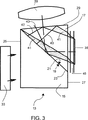
これらと他の目的を達成するために、本発明は、光源、DLP、投影レンズ、および第1と第2の間隔の置かれた表面を有するプリズムから構成される光学系であって、第1と第2の間隔の置かれた表面、光源、DLP、および投影レンズが互いに対して、光源からの光が第1と第2の間隔の置かれた表面を通ってDLPまで通過し、DLPの「オン」または「第1位置」ピクセルから反射された光が、この光が投影レンズの受光角内にあるような角度で投影レンズに向かって第2の間隔の置かれた表面で内面反射し、DLPの「オフ」または「第2位置」ピクセルから反射された光が、この光が投影レンズの受光角に入らないような角度で投影レンズに向かって第2の間隔の置かれた表面で内面反射するか、またはそうでなければその光が受光角から外れるようにプリズムを通過する(例えば、図3の光41の一番上側の束)ように向けられている光学系を提供する。
【0007】
好ましい実施の形態の説明
明細書に含まれ、その一部を構成する以下の図面は、本発明の好ましい実施の形態を示し、説明と共に、本発明の原理を説明するように働く。もちろん、図面および説明の両方が、説明のみを目的とするものであり、本発明を制限するものではないことが理解されよう。
【0008】
図に示したように、プリズム13は、プリズムの対角面23で薄い空気層により隔てられた2つの部材すなわち要素15、17からなる。要素15の表面19および要素17の表面21は、この対角面に沿って互いに面し、それぞれ、上述した第1と第2の間隔の置かれた表面を構成する。
【0009】
図1に示したように、照明系33からの光31が側面25を通ってプリズム13に進入する。プリズム対角面23でのこの光の入射角は、この光が対角面23を通過し、DLP35を照らすように臨界角未満である。
【0010】
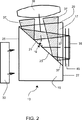
図2に示したように、「オン」位置にあるピクセルは、DLPの活性区域に対して垂直な方向で図1の入射照明光31を反射する。この光37は、臨界角よりも大きい、空気で間隔の置かれた対角面23での入射角を有し、したがって、この光の100%がこの対角面で反射する。特に、DLPからの反射光37は、空気の屈折率と比較した要素17の屈折率により定義される臨界角よりも大きな角度で要素17の表面21に当たる。
【0011】
光37は、側面27の鏡像である側面29を通ってプリズム13から出る。側面27および29のこの関係は、プリズム要素17は、「オン」ピクセルから反射した光ビーム37に沿って、実際には、平行平面板であることを意味する。これは、転じて、像形成路にある唯一の要素であるプリズム要素17が、コマ収差も非点収差も形成しないことを意味する。
【0012】
投影レンズ39は、「オン」ピクセルからの光を捕捉し、観察スクリーン(図示せず)上に所望の像を形成するように側面29の後に位置している。
【0013】
図3に示したように、「オフ」位置にあるピクセルは、光が投影レンズ39の入射瞳に効果的に進入しない(例えば、図3の光線43を参照)ような方向で図1の入射照明光31を反射する。すなわち、「オフ」ピクセルからの光41は、投影レンズの受光角内に入らない。
【0014】
実際には、プリズム13の側面25、27、および29は、フレネル反射を最小にするように従来の反射防止膜を有する。また、間隔の置かれた表面19、21は、照明光31のフレネル損失を減少させるために、臨界角に近い入射角のために最適化された反射防止膜を有する。
【0015】
空気層により隔てられる代わりに、表面19および21は、低屈折率膜により隔てられていても差し支えない。表面21で大きい臨界角を維持するために、要素17は、高屈折率ガラスから製造すべきである。要素15は、照明光31に色収差および他の収差を導入しないように同様のガラスから製造すべきである。そのような膜の利点としては、プリズム要素の組立てが容易になることおよび間隔の置かれた表面の埃および/または水の汚染による問題の排除が挙げられる。そのような汚染は、表面21での全反射が光を投影レンズに導く能力を損なうことがあり、高レベルの光損失となることがある。
【0016】
図1−3に示したように、DLPはカバープレート45により通常保護されている。所望であれば、このカバープレートは表面27に接着することができ、したがって、この系から2つのガラス/空気界面が除かれ、これにより、フレネル損失が減少する。
【0017】
上述したように、投影系の上述した構成は、以下の利点を達成する:
(1) 対角面23に沿った空気を含む間隔の幅およびウェッジは、「オン」ピクセルから投影レンズへの光路に影響を与えない。したがって、この傾斜空間に関連する非点収差およびコマ収差が除去される。
【0018】
(2) プリズム要素171つのみが像形成光路で動作する。したがって、プリズム要素15は、表面平坦度、表面位置調整、脈理、複屈折等の厳密な許容差のない低品質ガラスから製造できる。このようにして、このデバイスの全体の費用が低下する。
【0019】
本発明の好ましい実施の形態をここに記載したが、特許請求の範囲により定義された本発明の範囲から逸脱せずに、さらなる実施の形態が当業者により理解されるであろう。
【図面の簡単な説明】
【図1】 図1は、光源からの光の本発明によるDLPへの通過を示す図である
【図2】 図2は、DLPの「オン」ピクセルからの光の本発明による投影レンズへの通過を示す図である
【図3】 図3は、本発明によるDLPの「オフ」ピクセルからの光の光路を示す図である
【符号の説明】
13 プリズム
15、17 プリズム要素
19 第1の間隔の置かれた表面
21 第2の間隔の置かれた表面
23 対角面
25 プリズム入口表面
27 プリズム出口/入口表面
29 プリズム出口表面
31 照明光
33 照明系
35 DLP
37 「オン」ピクセルから反射した光
39 投影レンズ
41 「オフ」ピクセルから反射した光
43 「オフ」ピクセルからの光線
45 DLPカバープレート[0001]
FIELD OF THE INVENTION The present invention relates to optical systems for projection displays, and more particularly to optical systems of the type disclosed in US Pat. No. 5,552,922 (hereinafter referred to as the '922 patent), the contents of which are hereby incorporated by reference.
[0002]
Background of the Invention
The '922 patent discloses a system for transmitting illumination light from a light source to a digital light panel (DLP) and then from a DLP “on” pixel to a projection lens. While the system of the '922 patent works well, two areas have been recognized where the system can be modified to reduce costs and facilitate manufacturing.
[0003]
The first zone relates to the space containing the inclined air between the surfaces 18 and 20 of the '922 patent. Since light from “on” pixels passes through this space, the space can introduce astigmatism and coma into the projected image of the DLP unless the width and wedge of this space are carefully adjusted. This system becomes more difficult to manufacture because it is necessary to closely adjust the width and wedge of this space.
[0004]
The second zone, 'in the system of 922 patent, light from the "on" pixels, "surface 14, 16 of the 922 patent, and 18 surfaces 12 and of the optical elements and the patent is defined by 20 Related to the fact that it passes through both of the optical elements defined by. This means that both of these optical elements must be manufactured from high quality glass and meet stringent tolerances such as surface flatness, surface alignment, striae, birefringence, etc. To do. Such a requirement is undesirable because it increases the overall cost of the system.
[0005]
SUMMARY OF THE INVENTION In view of the foregoing, it is an object of the present invention to provide an improved optical system that transmits illumination light from a light source to a DLP and then transmits from the “on” pixel of the DLP to a projection lens. More particularly, it is an object of the present invention to provide a system of the general type disclosed in the '922 patent that is easier to manufacture and has reduced costs.
[0006]
To achieve these and other objects, the present invention provides an optical system comprising a light source, a DLP, a projection lens, and a prism having first and second spaced surfaces. And the second spaced surface, the light source, the DLP, and the projection lens with respect to each other, the light from the light source passes through the first and second spaced surfaces to the DLP, Light reflected from an “on” or “first position” pixel is internally reflected at a second spaced surface toward the projection lens at an angle such that the light is within the acceptance angle of the projection lens. , The light reflected from the “off” or “second position” pixel of the DLP at a second spaced surface towards the projection lens at an angle such that this light does not enter the acceptance angle of the projection lens. Reflect internally or otherwise the light It passes through the prism as out of the optical angular (e.g., uppermost bundle of
[0007]
The following drawings, which are included in and constitute a part of the description of the preferred embodiment, illustrate the preferred embodiment of the invention and, together with the description, serve to explain the principles of the invention. Of course, it will be understood that both the drawings and the description are for illustrative purposes only and are not intended to limit the invention.
[0008]
As shown, the
[0009]
As shown in FIG. 1, the
[0010]
As shown in FIG. 2, pixels in the “on” position reflect the
[0011]
Light 37 exits prism 13 through
[0012]
[0013]
As shown in FIG. 3, a pixel in the “off” position is incident in FIG. 1 in a direction such that light does not effectively enter the entrance pupil of projection lens 39 (see, for example,
[0014]
In practice, the
[0015]
Instead of being separated by an air layer, the
[0016]
As shown in FIGS. 1 to 3, the DLP is usually protected by a
[0017]
As mentioned above, the above-described configuration of the projection system achieves the following advantages:
(1) Spacing width and wedges including air along
[0018]
(2) Only one prism element 171 operates in the image forming optical path. Therefore, the
[0019]
While preferred embodiments of the invention have been described herein, further embodiments will be understood by those skilled in the art without departing from the scope of the invention as defined by the claims.
[Brief description of the drawings]
FIG. 1 is a diagram illustrating the passage of light from a light source to a DLP according to the present invention. FIG. 2 is a diagram of light from a “on” pixel of a DLP to a projection lens according to the present invention. FIG. 3 is a diagram showing an optical path of light from an “off” pixel of a DLP according to the present invention.
13 Prism
15, 17 Prism element
19 First spaced surface
21 Second spaced surface
23 Diagonal surface
25 Prism entrance surface
27 Prism exit / entrance surface
29 Prism exit surface
31 Illumination light
33 Lighting system
35 DLP
37 Light reflected from “on” pixels
39 Projection lens
41 Light reflected from “off” pixels
43 Rays from “off” pixels
45 DLP cover plate
Claims (2)
(a) 照明光を提供する光源、
(b) 共通平面に配置された選択的に調節可能な複数の反射素子であって、第1の位置と第2の位置との間で調節可能な反射素子、
(c) 主平面を有するレンズ、および
(d) 前記レンズと前記複数の反射素子との間に位置するプリズムであって、第1の要素と第2の要素からなり、当該第1の要素と第2の要素の間が対角面沿って空気層により隔てられているもの、
を有してなり、
前記第1の要素が前記対角面に沿う第1の表面を備え、前記第2の要素が前記対角面に沿う第2の表面を備え、前記第1の表面と前記第2の表面とが、前記空気層によって隔てられており、前記第2の要素が、光が前記プリズムから前記反射素子に出射し反射の後に前記プリズムに再入射する出射/入射面、及び、光がレンズに向けて出射する出射面を有し、
(i) 前記光源からの光が前記第1の表面と前記第2の表面を通って前記複数の反射素子まで到達し、
(ii) 前記第1の位置にある前記反射素子から反射された光が、前記共通平面の垂直方向に反射され、前記レンズに、前記レンズの受光角に入るような角度で入射するように前記第2の表面で反射され、
(iii) 前記第2の位置にある前記反射素子から反射された光が、前記レンズに入らない方向に前記第2の表面で反射され、
前記出射/入射面と前記出射面とが前記第2の表面についてお互いに鏡像関係にあることにより、前記出射/入射面に垂直に入射した光が前記出射面から垂直に出射し、前記第1の位置にある前記反射素子から反射された光と前記第2の位置にある前記反射素子から反射された光とが共に前記出射面から出射することを特徴とする像形成投影系。An image forming projection system, wherein the image forming projection system is
(a) a light source that provides illumination light;
(b) a plurality of selectively adjustable reflective elements disposed in a common plane, the reflective elements adjustable between a first position and a second position;
(c) a lens having a main plane, and
and (d) a prism located between the lens and the plurality of reflective elements, a first element made from a second element, the diagonal surface between said first and second elements Separated by air layers along,
Having
The first element comprises a first surface along the diagonal; the second element comprises a second surface along the diagonal; the first surface and the second surface; Are separated by the air layer, and the second element includes an exit / incident surface from which light exits the prism to the reflecting element and re-enters the prism after reflection, and the light is directed to the lens. And has an exit surface that exits
(i) light from said light source through said second surface and the first surface to reach the plurality of reflective elements,
(ii) The light reflected from the reflective element at the first position is reflected in a direction perpendicular to the common plane, and is incident on the lens at an angle that enters a light receiving angle of the lens. Reflected by the second surface,
(iii) the second light reflected from the reflective element in the position, is reflected by the second front surface in a direction that does not enter into the lens,
Since the exit / incident surface and the exit surface are mirror images of each other with respect to the second surface, light perpendicularly incident on the exit / incident surface is emitted perpendicularly from the exit surface, and the first surface An image forming projection system characterized in that both the light reflected from the reflecting element at the position and the light reflected from the reflecting element at the second position are emitted from the exit surface .
Applications Claiming Priority (3)
| Application Number | Priority Date | Filing Date | Title |
|---|---|---|---|
| US14144399P | 1999-06-29 | 1999-06-29 | |
| US60/141,443 | 1999-06-29 | ||
| PCT/US2000/007388 WO2001001195A1 (en) | 1999-06-29 | 2000-03-20 | Optical systems for projection displays |
Publications (3)
| Publication Number | Publication Date |
|---|---|
| JP2003503755A JP2003503755A (en) | 2003-01-28 |
| JP2003503755A5 JP2003503755A5 (en) | 2007-05-24 |
| JP5089841B2 true JP5089841B2 (en) | 2012-12-05 |
Family
ID=22495716
Family Applications (1)
| Application Number | Title | Priority Date | Filing Date |
|---|---|---|---|
| JP2001507143A Expired - Lifetime JP5089841B2 (en) | 1999-06-29 | 2000-03-20 | Optical system for projection display |
Country Status (7)
| Country | Link |
|---|---|
| US (1) | US6461000B1 (en) |
| EP (1) | EP1196819A4 (en) |
| JP (1) | JP5089841B2 (en) |
| KR (1) | KR100702736B1 (en) |
| CN (1) | CN1322370C (en) |
| TW (1) | TW448311B (en) |
| WO (1) | WO2001001195A1 (en) |
Families Citing this family (82)
| Publication number | Priority date | Publication date | Assignee | Title |
|---|---|---|---|---|
| DE69626202T2 (en) * | 1995-05-11 | 2003-09-25 | Digital Projection Ltd | PROJECTION DEVICE |
| JP2002350775A (en) * | 2001-05-30 | 2002-12-04 | Fuji Photo Optical Co Ltd | Projector |
| US6726332B2 (en) * | 2001-11-28 | 2004-04-27 | 3M Innovative Properties Company | TIR prism for DMD projector |
| US7207678B2 (en) * | 2001-12-31 | 2007-04-24 | Texas Instruments Incorporated | Prism for high contrast projection |
| WO2003075076A1 (en) * | 2002-02-28 | 2003-09-12 | 3M Innovative Properties Company | Compound polarization beam splitters |
| US6634756B1 (en) * | 2002-06-27 | 2003-10-21 | Koninklijke Philips Electronics N.V. | Beam-splitter folded path for rear projection displays |
| TW586020B (en) * | 2002-09-03 | 2004-05-01 | Young Optics Inc | Optical system for projection display apparatus |
| CN100588265C (en) * | 2004-07-22 | 2010-02-03 | 汤姆森许可公司 | Discrete high switching rate illumination geometry structure for single imager microdisplay |
| US20060139730A1 (en) * | 2004-12-23 | 2006-06-29 | Oehler Peter R | Illumination system with compact turning prism and projection system using same |
| TWI348634B (en) * | 2006-07-18 | 2011-09-11 | Young Optics Inc | Optical mouse |
| TWI331251B (en) * | 2006-09-22 | 2010-10-01 | Coretronic Corp | Optical projection apparatus and total internal reflection prism thereof |
| CN100443953C (en) * | 2006-10-25 | 2008-12-17 | 浙江大学 | Coaxial-observation UV projection irradiation device |
| US8210689B2 (en) * | 2007-12-31 | 2012-07-03 | 3M Innovative Properties Company | Projection system |
| US9158116B1 (en) | 2014-04-25 | 2015-10-13 | Osterhout Group, Inc. | Temple and ear horn assembly for headworn computer |
| US8220930B2 (en) * | 2008-03-25 | 2012-07-17 | Shanghai Lexvu Opto Microelectronics Technology Co., Ltd. | Integrated opto-electronic device and portable reflective projection system |
| CN102084177B (en) * | 2008-05-05 | 2013-04-10 | 3M创新有限公司 | Light source module |
| US20150277120A1 (en) | 2014-01-21 | 2015-10-01 | Osterhout Group, Inc. | Optical configurations for head worn computing |
| US9965681B2 (en) | 2008-12-16 | 2018-05-08 | Osterhout Group, Inc. | Eye imaging in head worn computing |
| US20150205111A1 (en) | 2014-01-21 | 2015-07-23 | Osterhout Group, Inc. | Optical configurations for head worn computing |
| US9229233B2 (en) | 2014-02-11 | 2016-01-05 | Osterhout Group, Inc. | Micro Doppler presentations in head worn computing |
| US9298007B2 (en) | 2014-01-21 | 2016-03-29 | Osterhout Group, Inc. | Eye imaging in head worn computing |
| US9366867B2 (en) | 2014-07-08 | 2016-06-14 | Osterhout Group, Inc. | Optical systems for see-through displays |
| US9952664B2 (en) | 2014-01-21 | 2018-04-24 | Osterhout Group, Inc. | Eye imaging in head worn computing |
| US9715112B2 (en) | 2014-01-21 | 2017-07-25 | Osterhout Group, Inc. | Suppression of stray light in head worn computing |
| US9400390B2 (en) | 2014-01-24 | 2016-07-26 | Osterhout Group, Inc. | Peripheral lighting for head worn computing |
| US8556472B2 (en) | 2010-09-28 | 2013-10-15 | Simon Magarill | Light reflectors and flood lighting systems |
| US9299194B2 (en) | 2014-02-14 | 2016-03-29 | Osterhout Group, Inc. | Secure sharing in head worn computing |
| US11103122B2 (en) | 2014-07-15 | 2021-08-31 | Mentor Acquisition One, Llc | Content presentation in head worn computing |
| US9575321B2 (en) | 2014-06-09 | 2017-02-21 | Osterhout Group, Inc. | Content presentation in head worn computing |
| US9448409B2 (en) | 2014-11-26 | 2016-09-20 | Osterhout Group, Inc. | See-through computer display systems |
| US9594246B2 (en) | 2014-01-21 | 2017-03-14 | Osterhout Group, Inc. | See-through computer display systems |
| US11227294B2 (en) | 2014-04-03 | 2022-01-18 | Mentor Acquisition One, Llc | Sight information collection in head worn computing |
| US10254856B2 (en) | 2014-01-17 | 2019-04-09 | Osterhout Group, Inc. | External user interface for head worn computing |
| US9939934B2 (en) | 2014-01-17 | 2018-04-10 | Osterhout Group, Inc. | External user interface for head worn computing |
| US20160019715A1 (en) | 2014-07-15 | 2016-01-21 | Osterhout Group, Inc. | Content presentation in head worn computing |
| US9671613B2 (en) | 2014-09-26 | 2017-06-06 | Osterhout Group, Inc. | See-through computer display systems |
| US9810906B2 (en) | 2014-06-17 | 2017-11-07 | Osterhout Group, Inc. | External user interface for head worn computing |
| US10684687B2 (en) | 2014-12-03 | 2020-06-16 | Mentor Acquisition One, Llc | See-through computer display systems |
| US20150277118A1 (en) | 2014-03-28 | 2015-10-01 | Osterhout Group, Inc. | Sensor dependent content position in head worn computing |
| US9366868B2 (en) | 2014-09-26 | 2016-06-14 | Osterhout Group, Inc. | See-through computer display systems |
| US10191279B2 (en) | 2014-03-17 | 2019-01-29 | Osterhout Group, Inc. | Eye imaging in head worn computing |
| US9529195B2 (en) | 2014-01-21 | 2016-12-27 | Osterhout Group, Inc. | See-through computer display systems |
| US10649220B2 (en) | 2014-06-09 | 2020-05-12 | Mentor Acquisition One, Llc | Content presentation in head worn computing |
| US9746686B2 (en) | 2014-05-19 | 2017-08-29 | Osterhout Group, Inc. | Content position calibration in head worn computing |
| US9829707B2 (en) | 2014-08-12 | 2017-11-28 | Osterhout Group, Inc. | Measuring content brightness in head worn computing |
| US9841599B2 (en) | 2014-06-05 | 2017-12-12 | Osterhout Group, Inc. | Optical configurations for head-worn see-through displays |
| US9529199B2 (en) | 2014-01-21 | 2016-12-27 | Osterhout Group, Inc. | See-through computer display systems |
| US9310610B2 (en) | 2014-01-21 | 2016-04-12 | Osterhout Group, Inc. | See-through computer display systems |
| US9753288B2 (en) | 2014-01-21 | 2017-09-05 | Osterhout Group, Inc. | See-through computer display systems |
| US9651784B2 (en) | 2014-01-21 | 2017-05-16 | Osterhout Group, Inc. | See-through computer display systems |
| US11669163B2 (en) | 2014-01-21 | 2023-06-06 | Mentor Acquisition One, Llc | Eye glint imaging in see-through computer display systems |
| US20150205135A1 (en) | 2014-01-21 | 2015-07-23 | Osterhout Group, Inc. | See-through computer display systems |
| US9836122B2 (en) | 2014-01-21 | 2017-12-05 | Osterhout Group, Inc. | Eye glint imaging in see-through computer display systems |
| US9766463B2 (en) | 2014-01-21 | 2017-09-19 | Osterhout Group, Inc. | See-through computer display systems |
| US11737666B2 (en) | 2014-01-21 | 2023-08-29 | Mentor Acquisition One, Llc | Eye imaging in head worn computing |
| US9532715B2 (en) | 2014-01-21 | 2017-01-03 | Osterhout Group, Inc. | Eye imaging in head worn computing |
| US11487110B2 (en) | 2014-01-21 | 2022-11-01 | Mentor Acquisition One, Llc | Eye imaging in head worn computing |
| US9811159B2 (en) | 2014-01-21 | 2017-11-07 | Osterhout Group, Inc. | Eye imaging in head worn computing |
| US11892644B2 (en) | 2014-01-21 | 2024-02-06 | Mentor Acquisition One, Llc | See-through computer display systems |
| US9494800B2 (en) | 2014-01-21 | 2016-11-15 | Osterhout Group, Inc. | See-through computer display systems |
| US9401540B2 (en) | 2014-02-11 | 2016-07-26 | Osterhout Group, Inc. | Spatial location presentation in head worn computing |
| US20150241964A1 (en) | 2014-02-11 | 2015-08-27 | Osterhout Group, Inc. | Eye imaging in head worn computing |
| US20160187651A1 (en) | 2014-03-28 | 2016-06-30 | Osterhout Group, Inc. | Safety for a vehicle operator with an hmd |
| US9423842B2 (en) | 2014-09-18 | 2016-08-23 | Osterhout Group, Inc. | Thermal management for head-worn computer |
| US9651787B2 (en) | 2014-04-25 | 2017-05-16 | Osterhout Group, Inc. | Speaker assembly for headworn computer |
| US9672210B2 (en) | 2014-04-25 | 2017-06-06 | Osterhout Group, Inc. | Language translation with head-worn computing |
| US10853589B2 (en) | 2014-04-25 | 2020-12-01 | Mentor Acquisition One, Llc | Language translation with head-worn computing |
| US10663740B2 (en) | 2014-06-09 | 2020-05-26 | Mentor Acquisition One, Llc | Content presentation in head worn computing |
| US9684172B2 (en) | 2014-12-03 | 2017-06-20 | Osterhout Group, Inc. | Head worn computer display systems |
| USD743963S1 (en) | 2014-12-22 | 2015-11-24 | Osterhout Group, Inc. | Air mouse |
| USD751552S1 (en) | 2014-12-31 | 2016-03-15 | Osterhout Group, Inc. | Computer glasses |
| USD753114S1 (en) | 2015-01-05 | 2016-04-05 | Osterhout Group, Inc. | Air mouse |
| US20160239985A1 (en) | 2015-02-17 | 2016-08-18 | Osterhout Group, Inc. | See-through computer display systems |
| CA2949845C (en) * | 2015-12-04 | 2020-10-13 | AGM Automotive, LLC | Illumination device for projecting light in a predetermined illumination pattern on a surface |
| US10684478B2 (en) | 2016-05-09 | 2020-06-16 | Mentor Acquisition One, Llc | User interface systems for head-worn computers |
| US9910284B1 (en) | 2016-09-08 | 2018-03-06 | Osterhout Group, Inc. | Optical systems for head-worn computers |
| US10824253B2 (en) | 2016-05-09 | 2020-11-03 | Mentor Acquisition One, Llc | User interface systems for head-worn computers |
| US10466491B2 (en) | 2016-06-01 | 2019-11-05 | Mentor Acquisition One, Llc | Modular systems for head-worn computers |
| US11409105B2 (en) | 2017-07-24 | 2022-08-09 | Mentor Acquisition One, Llc | See-through computer display systems |
| US10422995B2 (en) | 2017-07-24 | 2019-09-24 | Mentor Acquisition One, Llc | See-through computer display systems with stray light management |
| US10578869B2 (en) | 2017-07-24 | 2020-03-03 | Mentor Acquisition One, Llc | See-through computer display systems with adjustable zoom cameras |
| US10969584B2 (en) | 2017-08-04 | 2021-04-06 | Mentor Acquisition One, Llc | Image expansion optic for head-worn computer |
Family Cites Families (18)
| Publication number | Priority date | Publication date | Assignee | Title |
|---|---|---|---|---|
| NL8902205A (en) * | 1989-09-01 | 1991-04-02 | Philips Nv | PROJECTION SYSTEM. |
| JPH04270140A (en) * | 1990-06-21 | 1992-09-25 | Johnson Matthey Inc | Sealing glass composition and said composition containing electrically conductive component |
| JP2765780B2 (en) * | 1992-05-08 | 1998-06-18 | 株式会社キビ | Tatami edge folding method and device |
| US5552922A (en) * | 1993-04-12 | 1996-09-03 | Corning Incorporated | Optical system for projection display |
| US5309188A (en) * | 1993-05-21 | 1994-05-03 | David Sarnoff Research Center, Inc. | Coupling prism assembly and projection system using the same |
| GB2286895A (en) * | 1994-02-22 | 1995-08-30 | Rank Brimar Ltd | Spatial light modulator system |
| US5442414A (en) * | 1994-05-10 | 1995-08-15 | U. S. Philips Corporation | High contrast illumination system for video projector |
| KR960039944A (en) * | 1995-04-26 | 1996-11-25 | 윌리엄 이. 힐러 | Lighting optical system for spatial light modulator |
| DE69626202T2 (en) * | 1995-05-11 | 2003-09-25 | Digital Projection Ltd | PROJECTION DEVICE |
| JPH08313864A (en) * | 1995-05-23 | 1996-11-29 | Texas Instr Inc <Ti> | Projector device |
| JP3639388B2 (en) * | 1996-09-09 | 2005-04-20 | 三洋電機株式会社 | Projection display device |
| US5946139A (en) * | 1998-04-06 | 1999-08-31 | Unic View Ltd. | Compact monitor |
| US6249387B1 (en) | 1998-05-13 | 2001-06-19 | Texas Instruments Incorporated | Stable enhanced contrast optical system for high resolution displays |
| JP4983032B2 (en) * | 2006-02-08 | 2012-07-25 | ソニー株式会社 | DEMODULATION TABLE, DEMODULATION DEVICE AND METHOD, PROGRAM, AND RECORDING MEDIUM |
| JP4913528B2 (en) * | 2006-10-04 | 2012-04-11 | 日立アロカメディカル株式会社 | Ultrasonic diagnostic equipment |
| JP5442414B2 (en) * | 2009-12-08 | 2014-03-12 | タカノ株式会社 | Cutting training model teeth |
| JP5552922B2 (en) * | 2010-06-29 | 2014-07-16 | セントラル硝子株式会社 | Fission product separation material and method for producing the same, and fission product separation method using the separation material |
| KR101785177B1 (en) * | 2012-12-27 | 2017-11-06 | 알박 세이마쿠 가부시키가이샤 | Phase Shift Mask and Method For Producing Same |
-
2000
- 2000-03-20 CN CNB008096236A patent/CN1322370C/en not_active Expired - Fee Related
- 2000-03-20 JP JP2001507143A patent/JP5089841B2/en not_active Expired - Lifetime
- 2000-03-20 WO PCT/US2000/007388 patent/WO2001001195A1/en active IP Right Grant
- 2000-03-20 US US09/528,630 patent/US6461000B1/en not_active Expired - Lifetime
- 2000-03-20 KR KR1020017016745A patent/KR100702736B1/en not_active IP Right Cessation
- 2000-03-20 EP EP00919488A patent/EP1196819A4/en not_active Ceased
- 2000-03-29 TW TW089105994A patent/TW448311B/en not_active IP Right Cessation
Also Published As
| Publication number | Publication date |
|---|---|
| TW448311B (en) | 2001-08-01 |
| US6461000B1 (en) | 2002-10-08 |
| KR100702736B1 (en) | 2007-04-03 |
| KR20020021146A (en) | 2002-03-18 |
| EP1196819A1 (en) | 2002-04-17 |
| EP1196819A4 (en) | 2006-10-11 |
| WO2001001195A1 (en) | 2001-01-04 |
| JP2003503755A (en) | 2003-01-28 |
| CN1322370C (en) | 2007-06-20 |
| CN1375076A (en) | 2002-10-16 |
Similar Documents
| Publication | Publication Date | Title |
|---|---|---|
| JP5089841B2 (en) | Optical system for projection display | |
| US6808271B1 (en) | Projection type display apparatus | |
| JP4005915B2 (en) | Flat panel camera | |
| US7009765B2 (en) | Wide angle lens system having a distorted intermediate image | |
| US8014075B2 (en) | Projection type image display device | |
| US6406150B1 (en) | Compact rear projections system | |
| US6439726B1 (en) | System in which light is directed from a light source onto a surface | |
| JPH09500982A (en) | LCD projection display system | |
| JPH0387731A (en) | Image display device | |
| JPH09218379A (en) | Wide viewing angle liquid crystal projection lens system | |
| JPH02160208A (en) | Liquid crystal projecting display device | |
| US6601957B2 (en) | Projection-type image displaying device | |
| US6349006B1 (en) | Prism having two inner surfaces and outer shape regarded as plane parallel plate | |
| US6590714B2 (en) | Color combining optical system and projection type display apparatus having the same | |
| GB2343966A (en) | Bent optical projection lens unit for liquid crystal display | |
| EP1014159B1 (en) | Illumination apparatus and projection apparatus | |
| KR100584589B1 (en) | Projection lens unit and projection system employing the same | |
| US8215778B2 (en) | Projector apparatus | |
| US6522453B2 (en) | Projection device and a projection lens | |
| JPS6146810B2 (en) | ||
| US6457832B1 (en) | Illumination apparatus and projection apparatus compensating for transverse aberration at an illumination surface | |
| JP2004309765A (en) | Reflecting optical system and projector using reflecting optical system | |
| JP2005055866A (en) | Projection system and optical path transfer device thereof | |
| JPH0345987A (en) | Back project type display device | |
| JP3425583B2 (en) | Optical device |
Legal Events
| Date | Code | Title | Description |
|---|---|---|---|
| A521 | Request for written amendment filed |
Free format text: JAPANESE INTERMEDIATE CODE: A523 Effective date: 20070320 |
|
| A621 | Written request for application examination |
Free format text: JAPANESE INTERMEDIATE CODE: A621 Effective date: 20070320 |
|
| A131 | Notification of reasons for refusal |
Free format text: JAPANESE INTERMEDIATE CODE: A131 Effective date: 20100601 |
|
| A601 | Written request for extension of time |
Free format text: JAPANESE INTERMEDIATE CODE: A601 Effective date: 20100819 |
|
| A602 | Written permission of extension of time |
Free format text: JAPANESE INTERMEDIATE CODE: A602 Effective date: 20100826 |
|
| A521 | Request for written amendment filed |
Free format text: JAPANESE INTERMEDIATE CODE: A523 Effective date: 20101201 |
|
| A131 | Notification of reasons for refusal |
Free format text: JAPANESE INTERMEDIATE CODE: A131 Effective date: 20110329 |
|
| A601 | Written request for extension of time |
Free format text: JAPANESE INTERMEDIATE CODE: A601 Effective date: 20110616 |
|
| A602 | Written permission of extension of time |
Free format text: JAPANESE INTERMEDIATE CODE: A602 Effective date: 20110624 |
|
| A601 | Written request for extension of time |
Free format text: JAPANESE INTERMEDIATE CODE: A601 Effective date: 20110829 |
|
| A602 | Written permission of extension of time |
Free format text: JAPANESE INTERMEDIATE CODE: A602 Effective date: 20110905 |
|
| A521 | Request for written amendment filed |
Free format text: JAPANESE INTERMEDIATE CODE: A523 Effective date: 20110929 |
|
| TRDD | Decision of grant or rejection written | ||
| A01 | Written decision to grant a patent or to grant a registration (utility model) |
Free format text: JAPANESE INTERMEDIATE CODE: A01 Effective date: 20120814 |
|
| A01 | Written decision to grant a patent or to grant a registration (utility model) |
Free format text: JAPANESE INTERMEDIATE CODE: A01 |
|
| A61 | First payment of annual fees (during grant procedure) |
Free format text: JAPANESE INTERMEDIATE CODE: A61 Effective date: 20120912 |
|
| FPAY | Renewal fee payment (event date is renewal date of database) |
Free format text: PAYMENT UNTIL: 20150921 Year of fee payment: 3 |
|
| R150 | Certificate of patent or registration of utility model |
Free format text: JAPANESE INTERMEDIATE CODE: R150 Ref document number: 5089841 Country of ref document: JP Free format text: JAPANESE INTERMEDIATE CODE: R150 |
|
| R250 | Receipt of annual fees |
Free format text: JAPANESE INTERMEDIATE CODE: R250 |
|
| R250 | Receipt of annual fees |
Free format text: JAPANESE INTERMEDIATE CODE: R250 |
|
| R250 | Receipt of annual fees |
Free format text: JAPANESE INTERMEDIATE CODE: R250 |
|
| R250 | Receipt of annual fees |
Free format text: JAPANESE INTERMEDIATE CODE: R250 |
|
| R250 | Receipt of annual fees |
Free format text: JAPANESE INTERMEDIATE CODE: R250 |
|
| EXPY | Cancellation because of completion of term |