JP5089073B2 - Radially offset polishing pad - Google Patents
Radially offset polishing pad Download PDFInfo
- Publication number
- JP5089073B2 JP5089073B2 JP2006109276A JP2006109276A JP5089073B2 JP 5089073 B2 JP5089073 B2 JP 5089073B2 JP 2006109276 A JP2006109276 A JP 2006109276A JP 2006109276 A JP2006109276 A JP 2006109276A JP 5089073 B2 JP5089073 B2 JP 5089073B2
- Authority
- JP
- Japan
- Prior art keywords
- polishing
- radial
- groove
- polishing pad
- microchannels
- Prior art date
- Legal status (The legal status is an assumption and is not a legal conclusion. Google has not performed a legal analysis and makes no representation as to the accuracy of the status listed.)
- Active
Links
Images


Classifications
-
- B—PERFORMING OPERATIONS; TRANSPORTING
- B24—GRINDING; POLISHING
- B24B—MACHINES, DEVICES, OR PROCESSES FOR GRINDING OR POLISHING; DRESSING OR CONDITIONING OF ABRADING SURFACES; FEEDING OF GRINDING, POLISHING, OR LAPPING AGENTS
- B24B37/00—Lapping machines or devices; Accessories
- B24B37/11—Lapping tools
- B24B37/20—Lapping pads for working plane surfaces
- B24B37/26—Lapping pads for working plane surfaces characterised by the shape of the lapping pad surface, e.g. grooved
-
- D—TEXTILES; PAPER
- D21—PAPER-MAKING; PRODUCTION OF CELLULOSE
- D21H—PULP COMPOSITIONS; PREPARATION THEREOF NOT COVERED BY SUBCLASSES D21C OR D21D; IMPREGNATING OR COATING OF PAPER; TREATMENT OF FINISHED PAPER NOT COVERED BY CLASS B31 OR SUBCLASS D21G; PAPER NOT OTHERWISE PROVIDED FOR
- D21H27/00—Special paper not otherwise provided for, e.g. made by multi-step processes
- D21H27/18—Paper- or board-based structures for surface covering
- D21H27/20—Flexible structures being applied by the user, e.g. wallpaper
-
- D—TEXTILES; PAPER
- D21—PAPER-MAKING; PRODUCTION OF CELLULOSE
- D21H—PULP COMPOSITIONS; PREPARATION THEREOF NOT COVERED BY SUBCLASSES D21C OR D21D; IMPREGNATING OR COATING OF PAPER; TREATMENT OF FINISHED PAPER NOT COVERED BY CLASS B31 OR SUBCLASS D21G; PAPER NOT OTHERWISE PROVIDED FOR
- D21H27/00—Special paper not otherwise provided for, e.g. made by multi-step processes
- D21H27/001—Release paper
-
- D—TEXTILES; PAPER
- D21—PAPER-MAKING; PRODUCTION OF CELLULOSE
- D21H—PULP COMPOSITIONS; PREPARATION THEREOF NOT COVERED BY SUBCLASSES D21C OR D21D; IMPREGNATING OR COATING OF PAPER; TREATMENT OF FINISHED PAPER NOT COVERED BY CLASS B31 OR SUBCLASS D21G; PAPER NOT OTHERWISE PROVIDED FOR
- D21H27/00—Special paper not otherwise provided for, e.g. made by multi-step processes
- D21H27/30—Multi-ply
- D21H27/32—Multi-ply with materials applied between the sheets
- D21H27/34—Continuous materials, e.g. filaments, sheets, nets
- D21H27/36—Films made from synthetic macromolecular compounds
Description
本発明は一般にケミカルメカニカルポリッシング用の研磨パッドの分野に関する。特に、本発明は、磁性基材、光学基材及び半導体基材を化学機械研磨するのに有用なコンディショニングされた研磨パッドに関する。 The present invention relates generally to the field of polishing pads for chemical mechanical polishing. In particular, the present invention relates to a conditioned polishing pad useful for chemical mechanical polishing of magnetic, optical and semiconductor substrates.
集積回路及び他の電子素子の製造においては、導体、半導体及び絶縁材料の多数の層を半導体ウェーハの表面に付着させたり同表面から除去したりする。導体、半導体及び絶縁材料の薄い層は、多数の付着技術を使用して付着させることができる。最新のウェーハ加工で一般的な付着技術としては、とりわけ、スパッタリングとしても知られる物理蒸着法(PVD)、化学蒸着法(CVD)、プラズマ増強化学蒸着法(PECVD)及び電気化学的めっき法がある。一般的な除去技術としては、とりわけ、湿式及び乾式の等方性及び異方性エッチングがある。 In the manufacture of integrated circuits and other electronic devices, multiple layers of conductors, semiconductors, and insulating materials are deposited on or removed from the surface of a semiconductor wafer. Thin layers of conductors, semiconductors and insulating materials can be deposited using a number of deposition techniques. Common deposition techniques in modern wafer processing include, among others, physical vapor deposition (PVD), also known as sputtering, chemical vapor deposition (CVD), plasma enhanced chemical vapor deposition (PECVD), and electrochemical plating. . Common removal techniques include wet and dry isotropic and anisotropic etching, among others.
材料層が逐次に付着され、除去されるにつれ、ウェーハの一番上の表面が平坦でなくなる。後続の半導体加工(たとえばメタライゼーション)はウェーハが平坦面を有することを要するため、ウェーハは平坦化されなければならない。望ましくない表面トポロジーならびに表面欠陥、たとえば粗面、凝集した材料、結晶格子の損傷、スクラッチ及び汚染された層又は材料を除去するためにはプラナリゼーションが有用である。プラナリゼーションは、ウェーハスケールで、均一さの観点で計測される。一般に、薄膜厚さは、ウェーハ表面上の数十ないし数百の地点で計測され、標準偏差が計算される。プラナリゼーションはまた、素子構造スケールでも計測される。このナノトポググラフィーは、とりわけ、ディッシング及びエロージョンの観点で計測される。一般に、ナノトポググラフィーは、比較的高い振動数で解析されるが、より小さな面積で計測される。 As the material layer is deposited and removed sequentially, the top surface of the wafer becomes non-planar. Since subsequent semiconductor processing (eg metallization) requires the wafer to have a flat surface, the wafer must be planarized. Planarization is useful for removing undesired surface topologies and surface defects such as rough surfaces, agglomerated materials, crystal lattice damage, scratches and contaminated layers or materials. Planarization is measured at the wafer scale in terms of uniformity. Generally, the thin film thickness is measured at several tens to several hundreds of points on the wafer surface, and the standard deviation is calculated. Planarization is also measured at the device structure scale. This nanotopography is measured in particular in terms of dishing and erosion. In general, nanotopography is analyzed at a relatively high frequency but is measured in a smaller area.
ケミカルメカニカルプラナリゼーション又はケミカルメカニカルポリッシング(CMP)は、半導体ウェーハのような加工物を平坦化又は研磨するために使用される一般的な技術である。従来のCMPでは、ウェーハキャリヤ又は研磨ヘッドがキャリヤアセンブリに取り付けられる。研磨ヘッドがウェーハを保持し、CMP装置内で研磨パッドの研磨層と接する状態に配置する。キャリヤアセンブリがウェーハと研磨パッドとの間に制御可能な圧を供給する。それと同時に、スラリー又は他の研磨媒体を研磨パッド上に流し、ウェーハと研磨層との間の隙間に流し込む。研磨を起こさせるためには、研磨パッド及びウェーハを互いに対して回転させる。研磨層及び表面上の研磨媒体の化学的かつ機械的作用によってウェーハ表面が研磨され、平坦化される。研磨パッドがウェーハの下で回転すると、ウェーハは、ウェーハ表面が研磨層と直接対面するところの、一般に環状の研磨トラック又は研磨領域を描き出す。 Chemical mechanical planarization or chemical mechanical polishing (CMP) is a common technique used to planarize or polish workpieces such as semiconductor wafers. In conventional CMP, a wafer carrier or polishing head is attached to the carrier assembly. A polishing head holds the wafer and places it in contact with the polishing layer of the polishing pad in the CMP apparatus. A carrier assembly provides a controllable pressure between the wafer and the polishing pad. At the same time, slurry or other polishing media is flowed over the polishing pad and into the gap between the wafer and the polishing layer. To cause polishing, the polishing pad and wafer are rotated relative to each other. The wafer surface is polished and planarized by the chemical and mechanical action of the polishing layer and polishing media on the surface. As the polishing pad rotates under the wafer, the wafer delineates a generally annular polishing track or polishing area where the wafer surface directly faces the polishing layer.
研磨層を設計する際の重要な考慮事項としては、とりわけ、研磨層の面上の研磨媒体の分布、研磨トラックへの新鮮な研磨媒体の流れ、研磨トラックからの使用済み研磨媒体の流れ及び本質的に使用されないまま研磨ゾーンを通過する研磨媒体の量がある。これらの考慮事項に対処する一つの方法は、溝付きのマクロテクスチャを研磨層に設けることである。何年にもわたり、多くの異なる溝パターン及び配置が具現化されてきた。典型的な溝パターンとしては、とりわけ、半径方向、同心円状、デカルト格子状及びらせん状がある。 Important considerations when designing the polishing layer include, among other things, the distribution of the polishing media on the surface of the polishing layer, the flow of fresh polishing media to the polishing track, the flow and nature of the used polishing media from the polishing track. There is an amount of polishing media that passes through the polishing zone without being used. One way to address these considerations is to provide a grooved macrotexture in the polishing layer. Over the years, many different groove patterns and arrangements have been implemented. Typical groove patterns include radial, concentric, Cartesian and spiral, among others.
研磨媒体の分布及び流れに加えて、溝パターン及び配置が、CMP加工の他の重要な側面及び究極的にはウェーハの平坦さ、たとえば研磨速度、エッジ効果、ディッシングなどに影響する。さらには、溝パターン及び配置は、「溝パターン転写」として知られる現象によってウェーハ平坦さに影響する。この現象の結果は、特定の溝パターンが、研磨パッド上の溝のパターンに対応するコヒーレント構造をウェーハ表面に形成させることである。重大なことには、周方向の溝(研磨パッド速度に正接する線とで小さな角度を形成する溝)、すなわち円形の溝、円形のx−y溝又はらせん溝が、x−y溝又は半径方向の溝よりも顕著な溝パターン転写を生じさせる。 In addition to the distribution and flow of the polishing media, the groove pattern and placement affects other important aspects of CMP processing and ultimately wafer flatness, such as polishing rate, edge effects, dishing, and the like. Furthermore, the groove pattern and placement affects wafer flatness by a phenomenon known as “groove pattern transfer”. The result of this phenomenon is that a particular groove pattern forms a coherent structure on the wafer surface corresponding to the pattern of grooves on the polishing pad. Significantly, circumferential grooves (grooves that form a small angle with a line tangential to the polishing pad velocity), ie circular grooves, circular xy grooves or spiral grooves, are xy grooves or radii. This produces a groove pattern transfer that is more pronounced than the directional groove.
一貫した研磨性能のために一貫した研磨面を維持するには研磨パッドのコンディショニングが重要である。時間とともに、研磨パッドの研磨面はすりへり、研磨面のミクロテクスチャが平滑化(「グレージング」)されてゆく。さらには、CMP加工からの研磨くずが、スラリーが研磨面上を流れるときに通過するミクロチャネルを目詰まりさせることがある。これが起こると、CMP加工の研磨速度は低下し、これが、ウェーハ間又はウェーハ内で不均一な研磨を生じさせかねない。定期的又は連続的な「インサイチュ」のコンディショニングが、CMP加工で所望の研磨速度及び均一さを維持するのに有用な新たなテクスチャを研磨面上に創出する。 Polishing pad conditioning is important to maintain a consistent polishing surface for consistent polishing performance. Over time, the polishing surface of the polishing pad becomes worn and the microtexture of the polishing surface is smoothed (“glazed”). Furthermore, polishing litter from the CMP process can clog the microchannels through which the slurry flows as it flows over the polishing surface. When this occurs, the polishing rate of the CMP process decreases, which can cause uneven polishing between wafers or within a wafer. Regular or continuous “in situ” conditioning creates new textures on the polishing surface that are useful in maintaining the desired polishing rate and uniformity in the CMP process.
従来の研磨パッドコンディショニングは、コンディショニングディスクを用いて研磨面を機械的に研ぐことによって達成される。コンディショニングディスクは、一般には埋め込まれたダイヤモンド点で構成される粗いコンディショニング面を有する。コンディショニングディスクは、CMP加工の中断中又はCMP加工が実施されている間に研磨面と接触する。一般に、コンディショニングディスクは、研磨パッドの回転軸に対して固定された位置で回転し、研磨パッドが回転すると同時に環状のコンディショニング領域を描き出す。上記のようなコンディショニング加工は、研磨テーブルの線速度がコンディショニングディスク上の任意の点の線速度を超えるため、周方向に偏った向きを一般にもつミクロチャネルを有するコンディショニング領域で均一なコンディショニングを生じさせる。 Conventional polishing pad conditioning is accomplished by mechanically sharpening the polishing surface using a conditioning disk. Conditioning disks typically have a rough conditioning surface comprised of embedded diamond points. The conditioning disk contacts the polishing surface while the CMP process is interrupted or while the CMP process is being performed. In general, the conditioning disk rotates at a fixed position with respect to the rotation axis of the polishing pad, and draws an annular conditioning region at the same time as the polishing pad rotates. Conditioning as described above results in uniform conditioning in a conditioning region having microchannels that generally have a circumferentially biased orientation because the linear velocity of the polishing table exceeds the linear velocity at any point on the conditioning disk. .
研磨面上の研磨媒体の流れを増すための不均一コンディショニングが従来技術で開示されている。たとえば、米国特許第5,216,843号で、Breivogelらは、ダイヤモンド点コンディショニング加工によって形成される周方向のマクロ溝及び半径方向のマクロ溝を有する研磨パッドを開示している。しかし、Breivogelらの研磨パッドは、望ましくない溝パターン転写の影響をこうむる周方向の溝を含む。この溝パターン転写は、研磨不足のウェーハ領域につながる望ましくないコヒーレント構造を有する不均一なウェーハを造り出すおそれがある。溝パターン転写から生じるコヒーレント構造は、一般には高さが数十ナノメートル以上であるため、その後の半導体ウェーハ製造には受け入れられない。 Non-uniform conditioning to increase the flow of polishing media over the polishing surface has been disclosed in the prior art. For example, in US Pat. No. 5,216,843, Breivogel et al. Discloses a polishing pad having circumferential and radial macrogrooves formed by a diamond point conditioning process. However, the Breivogel et al. Polishing pad includes circumferential grooves that suffer from undesirable groove pattern transfer effects. This groove pattern transfer can create non-uniform wafers with undesirable coherent structures that lead to underpolished wafer areas. The coherent structure resulting from the groove pattern transfer is generally unacceptable for subsequent semiconductor wafer manufacturing because it is typically several tens of nanometers or higher in height.
CMP加工における研磨媒体の分布及び流れを制御し、より高い平坦度の均一なウェーハを製造する研磨パッドが要望される。 There is a need for a polishing pad that controls the distribution and flow of the polishing media in CMP processing to produce a higher flatness, uniform wafer.
本発明の一つの態様は、a)回転中心を有し、前記回転中心と同心であり、ある幅を有する環状研磨トラックを含む研磨層であって、前記環状研磨トラックの幅が、溝パターン転写を減らすために非半径方向の溝を有しないものであり、非半径方向の溝が、前記回転中心に対して周方向に30°範囲内の向きを有するものである研磨層、及びb)前記研磨層中の、前記環状研磨トラックの幅の範囲内にある複数の半径方向のミクロチャネルであって、大多数が、主として半径方向の向きを有し、50μm未満の平均幅を有する半径方向のミクロチャネルを含む、磁性基材、光学基材及び半導体基材の少なくとも一つを研磨するのに有用な研磨パッドを含む。 One aspect of the present invention is a polishing layer comprising an annular polishing track having a rotation center, concentric with the rotation center, and having a certain width, wherein the width of the annular polishing track is a groove pattern transfer. A non-radial groove in order to reduce the polishing layer, the non-radial groove having a direction within a range of 30 ° in the circumferential direction with respect to the rotation center, and b) A plurality of radial microchannels in the polishing layer that are within the width of the annular polishing track, the majority having a predominantly radial orientation and an average width of less than 50 μm A polishing pad useful for polishing at least one of a magnetic substrate, an optical substrate, and a semiconductor substrate, including microchannels.
本発明のもう一つの態様は、a)回転中心を有し、前記回転中心と同心であり、ある幅を有する環状研磨トラックを含む研磨層であって、前記環状研磨トラックの幅が半径方向の溝を含むものであり、前記半径方向の溝が、ある平均断面積を有するものである研磨層、及びb)前記研磨層中の、前記環状研磨トラックの幅の範囲内にある複数の半径方向のミクロチャネルであって、前記半径方向の溝の平均断面積の10分の1以下である平均断面積を有し、大多数が主として半径方向の向きを有する半径方向のミクロチャネルを含む、磁性基材、光学基材及び半導体基材の少なくとも一つを研磨するのに有用な研磨パッドを含む。 Another aspect of the present invention is a polishing layer comprising an annular polishing track having a rotation center, concentric with the rotation center, and having a width, wherein the annular polishing track has a width in the radial direction. A polishing layer comprising a groove, wherein the radial groove has an average cross-sectional area; and b) a plurality of radial directions within the width of the annular polishing track in the polishing layer. A magnetic channel comprising a radial microchannel having a mean cross-sectional area that is less than or equal to one tenth of a mean cross-sectional area of the radial groove, the majority having a predominantly radial orientation A polishing pad useful for polishing at least one of a substrate, an optical substrate, and a semiconductor substrate is included.
本発明のもう一つの態様は、磁性基材、光学基材及び半導体基材の少なくとも一つを研磨媒体の存在下で研磨する方法であって、回転中心を有し、前記回転中心と同心であり、ある幅を有する環状研磨トラックを含む研磨層であって、前記環状研磨トラックの幅が、溝パターン転写を減らすために非半径方向の溝を有しないものであり、非半径方向の溝が、前記回転中心に対して周方向に30°範囲内の向きを有するものである研磨層、及び前記研磨層中の、前記環状研磨トラックの幅の範囲内にある複数の半径方向のミクロチャネルであって、大多数が、主として半径方向の向きを有し、50μm未満の平均幅を有する半径方向のミクロチャネルを含む研磨パッドを用いて研磨を実施すること、及び研磨中に前記パッドをコンディショニングしてさらなる半径方向のミクロチャネルを設けること、を含む方法を含む。 Another aspect of the present invention is a method for polishing at least one of a magnetic substrate, an optical substrate, and a semiconductor substrate in the presence of a polishing medium, having a rotation center, and being concentric with the rotation center. A polishing layer comprising an annular polishing track having a width, the width of the annular polishing track having no non-radial grooves to reduce groove pattern transfer; A polishing layer having an orientation within a range of 30 ° circumferentially with respect to the center of rotation, and a plurality of radial microchannels in the polishing layer within a width of the annular polishing track. The majority performing polishing with a polishing pad comprising radial microchannels having a predominantly radial orientation and an average width of less than 50 μm, and conditioning said pad during polishing Providing a micro-channel of a further radially Te, the method comprising.
本発明のもう一つの態様は、磁性基材、光学基材及び半導体基材の少なくとも一つを研磨媒体の存在下で研磨する方法であって、回転中心を有し、前記回転中心と同心であり、ある幅を有する環状研磨トラックを含む研磨層であって、前記環状研磨トラックの幅が半径方向の溝を含むものであり、前記半径方向の溝が、ある平均断面積を有するものである研磨層、及び前記研磨層中の、前記環状研磨トラックの幅の範囲内にある複数の半径方向のミクロチャネルであって、前記半径方向の溝の平均断面積の10分の1以下である平均断面積を有し、大多数が主として半径方向の向きを有する半径方向のミクロチャネルを含む研磨パッドを用いて研磨を実施すること、及び研磨中に前記パッドをコンディショニングしてさらなる半径方向のミクロチャネルを設けること、を含む方法を含む。 Another aspect of the present invention is a method for polishing at least one of a magnetic substrate, an optical substrate, and a semiconductor substrate in the presence of a polishing medium, having a rotation center, and being concentric with the rotation center. A polishing layer including an annular polishing track having a certain width, wherein the width of the annular polishing track includes a radial groove, and the radial groove has an average cross-sectional area; A polishing layer, and a plurality of radial microchannels in the polishing layer that are within the width of the annular polishing track, the average being no more than one-tenth of the average cross-sectional area of the radial grooves Performing polishing using a polishing pad having a cross-sectional area, the majority comprising radial microchannels having a predominantly radial orientation, and conditioning said pad during polishing to provide further radial mixing. Providing a channel, the method comprising.
本発明は、得られる研磨基材に対する溝パターン転写効果を減らすマクロおよびミクロテクスチャを有する研磨パッドに関する。半径方向のコンディショニングが磁性基材、光学基材及び半導体基材上の表面の不均一さを減らすということが見いだされた。本明細書に関して、半径方向とは、研磨パッドの中心から周囲までの直線(「半径方向」)の60°範囲内の経路をいう。好ましくは、ミクロチャネルは、半径方向の45°範囲内、もっとも好ましくは半径方向の30°範囲内である。コンディショニングによって形成される半径方向のミクロチャネルは、溝パターン転写現象に伴う研磨不足領域を減らすことができる、外方へのスラリー分布を促進することができる。一般に、半径方向とともにミクロチャネルの割合が大きくなればなるほど、研磨から生じる研磨不足領域は減る。本明細書に関して、半径方向に偏ったミクロチャネルの大多数とは、線合計によって計測される半径方向のミクロチャネルの合計が、線合計によって計測される非半径方向のミクロチャネルの合計よりも大きいことをいう。これらの半径方向にコンディショニングされたパッドは、基材を研磨媒体で研磨するとき、ミクロチャネルの頻度に対応するスケールでウェーハの均一さを促進することができる。本明細書で使用する「研磨媒体」は、粒子含有研磨溶液及び非粒子含有研磨溶液、たとえば無砥粒反応液研磨溶液を含む。 The present invention relates to a polishing pad having macro and micro texture that reduces the effect of transferring a groove pattern to the resulting polishing substrate. It has been found that radial conditioning reduces surface non-uniformities on magnetic, optical and semiconductor substrates. As used herein, radial refers to a path within a 60 ° range of a straight line (“radial”) from the center to the periphery of the polishing pad. Preferably, the microchannel is in a 45 ° range in the radial direction, most preferably in a 30 ° range in the radial direction. Radial microchannels formed by conditioning can promote outward slurry distribution, which can reduce under-polished areas associated with groove pattern transfer phenomena. In general, the greater the proportion of microchannels along with the radial direction, the less polished area that results from polishing. For the purposes of this specification, the majority of radially biased microchannels means that the sum of the radial microchannels measured by the line sum is greater than the sum of the non-radial microchannels measured by the line sum. That means. These radially conditioned pads can promote wafer uniformity on a scale that corresponds to the frequency of the microchannels when the substrate is polished with a polishing medium. As used herein, “polishing media” includes particle-containing polishing solutions and non-particle-containing polishing solutions, such as abrasive-free reaction liquid polishing solutions.
典型的なポリマー研磨パッド材料としては、ポリカーボネート、ポリスルホン、ナイロン、ポリエーテル類、ポリエステル類、ポリエーテル−ポリエステルコポリマー、アクリル系ポリマー、ポリメチルメタクリレート、ポリ塩化ビニル、ポリエチレンコポリマー、ポリブタジエン、ポリエチレンイミン、ポリウレタン類、ポリエーテルスルホン、ポリエーテルイミド、ポリケトン類、エポキシ樹脂、シリコーン類、それらのコポリマー及びそれらの混合物がある。ポリマー材料は、好ましくはポリウレタンであり、もっとも好ましくは架橋ポリウレタン、たとえばRohm and Haas Electronic Materials CMP Technologies製のIC1000(商標)及びVisionPad(商標)研磨パッドである。これらのパッドは一般に、二官能性又は多官能性イソシアネート類から誘導されるポリウレタン類、たとえばポリエーテルウレア、ポリイソシアヌレート、ポリウレタン類、ポリウレア、ポリウレタンウレア、それらのコポリマー及びそれらの混合物で構成される。 Typical polymer polishing pad materials include polycarbonate, polysulfone, nylon, polyethers, polyesters, polyether-polyester copolymers, acrylic polymers, polymethyl methacrylate, polyvinyl chloride, polyethylene copolymers, polybutadiene, polyethyleneimine, polyurethane , Polyethersulfones, polyetherimides, polyketones, epoxy resins, silicones, copolymers thereof and mixtures thereof. The polymeric material is preferably a polyurethane, most preferably a cross-linked polyurethane, such as IC1000 ™ and VisionPad ™ polishing pads from Rohm and Haas Electronic Materials CMP Technologies. These pads are generally composed of polyurethanes derived from difunctional or polyfunctional isocyanates such as polyether ureas, polyisocyanurates, polyurethanes, polyureas, polyurethane ureas, copolymers thereof and mixtures thereof. .
これらの研磨パッドは、多孔性であることもできるし、無孔性であることもできる。多孔性であるならば、これらの研磨パッドは一般に、少なくとも0.1容量%の気孔率を有する。この気孔率が、研磨液を移動させる研磨パッドの能力に寄与する。好ましくは、研磨パッドは、0.2〜70容量%の気孔率を有する。もっとも好ましくは、研磨パッドは、0.25〜60容量%の気孔率を有する。好ましくは、気孔又は充填剤粒子は、重量平均直径(weight average diameter)が1〜100μmである。もっとも好ましくは、気孔又は充填剤粒子は、重量平均直径が10〜90μmである。さらには、10〜30μm(もっとも好ましくは15〜25μm)の重量平均直径が研磨性能をさらに改善することができる。発泡した中空ポリマー微小球の重量平均直径の公称範囲は一般には10〜50μmである。場合によっては、非発泡の中空ポリマー微小球を液体プレポリマーブレンドに直接加えることも可能である。一般には、非発泡微小球は、キャスティング中にインサイチュで発泡させる。 These polishing pads can be porous or non-porous. If porous, these polishing pads generally have a porosity of at least 0.1% by volume. This porosity contributes to the ability of the polishing pad to move the polishing liquid. Preferably, the polishing pad has a porosity of 0.2 to 70% by volume. Most preferably, the polishing pad has a porosity of 0.25-60% by volume. Preferably, the pores or filler particles have a weight average diameter of 1 to 100 μm. Most preferably, the pores or filler particles have a weight average diameter of 10 to 90 μm. Furthermore, a weight average diameter of 10 to 30 μm (most preferably 15 to 25 μm) can further improve the polishing performance. The nominal range of the weight average diameter of the expanded hollow polymer microspheres is generally 10-50 μm. In some cases, non-foamed hollow polymer microspheres can be added directly to the liquid prepolymer blend. In general, non-expanded microspheres are expanded in situ during casting.
気孔は、予備発泡させた、又はインサイチュで発泡させる中空の微小球をキャスティングすることによって、発泡剤を使用することによって、溶解ガス、たとえばアルゴン、二酸化炭素、ヘリウム、窒素及び空気又は超臨界流体、たとえば超臨界二酸化炭素の使用によって、ポリマー粒子を焼結させることによって、選択的溶解によっては、機械的通気、たとえば攪拌によって、又は接着剤を使用してポリマー粒子を凝集させることによって、導入することが可能である。 The pores can be dissolved gas, for example argon, carbon dioxide, helium, nitrogen and air or supercritical fluids, by using a blowing agent by casting hollow microspheres that have been pre-foamed or foamed in situ. Introducing, for example, by using supercritical carbon dioxide, by sintering the polymer particles, by selective dissolution, by mechanical ventilation, for example by stirring, or by agglomerating the polymer particles using an adhesive. Is possible.
加えて、ポリマー研磨パッドはポリマー膜形成材料を含むことができ、その材料の液状の溶剤溶液を形成し、溶液の層を乾燥させると、常温固体のポリマー膜(すなわち、通常の大気温度で固体)が形成する。ポリマー材料は、直鎖状のポリマー又はそのブレンドならびに添加剤、たとえば硬化剤、着色剤、可塑剤、安定剤及び充填剤からなることができる。典型的なポリマーとしては、ポリウレタンポリマー、ハロゲン化ビニルポリマー、ポリアミド、ポリエステルアミド、ポリエステル、ポリカーボネート類、ポリビニルブチラール、ポリ−α−メチルスチレン、ポリ塩化ビニリデン、アクリル酸及びメタクリル酸のアルキルエステル類、クロロスルホン化ポリエチレン、ブタジエンとアクリロニトリルとのコポリマー、セルロースエステル類及びエーテル類、ポリスチレンならびにそれらの組み合わせがある。好ましくは、多孔性の凝固研磨パッドは、ポリウレタンポリマーで形成された多孔性マトリックスを有する。もっとも好ましくは、多孔性研磨パッドは、ポリエーテルウレタンポリマーをポリ塩化ビニルで凝固させることで形成され、たとえば、Rohm and Haas Electronic Materials CMP TechnologiesのPolitex(商標)研磨パッドである。凝固マトリックスをフェルトタイプ又はフィルムベースのマトリックス、たとえばMylar(商標)ポリエチレンテレフタレートフィルムに付着させることが可能である。多孔性マトリックスは、非繊維質研磨層を有する。本明細書に関して、研磨層とは、研磨パッドのうち研磨中に基材と接触することができる部分である。独立気泡構造又は非網状構造が受け入れられるが、もっとも有利には、この構造は、気泡どうしを接続する微孔通路を含む連続気泡構造又は細網状構造である。微孔性細網状構造は、気体を気孔に通すが、研磨中に研磨パッドへのスラリー浸透を制限して、より均一な研磨パッド厚さを維持する。 In addition, the polymer polishing pad can include a polymer film-forming material that forms a liquid solvent solution of the material, and when the solution layer is dried, the polymer film that is solid at room temperature (ie, solid at normal atmospheric temperature) ) Form. The polymeric material can consist of linear polymers or blends thereof and additives such as curing agents, colorants, plasticizers, stabilizers and fillers. Typical polymers include polyurethane polymers, halogenated vinyl polymers, polyamides, polyester amides, polyesters, polycarbonates, polyvinyl butyral, poly-α-methylstyrene, polyvinylidene chloride, alkyl esters of acrylic acid and methacrylic acid, chloro There are sulfonated polyethylene, copolymers of butadiene and acrylonitrile, cellulose esters and ethers, polystyrene and combinations thereof. Preferably, the porous coagulated polishing pad has a porous matrix formed of a polyurethane polymer. Most preferably, the porous polishing pad is formed by coagulating a polyetherurethane polymer with polyvinyl chloride, such as the Politex ™ polishing pad from Rohm and Haas Electronic Materials CMP Technologies. It is possible to attach the coagulation matrix to a felt type or film-based matrix, such as Mylar ™ polyethylene terephthalate film. The porous matrix has a non-fibrous abrasive layer. For purposes of this specification, a polishing layer is a portion of a polishing pad that can contact a substrate during polishing. A closed cell structure or a non-reticulated structure is acceptable, but most advantageously, this structure is an open cell structure or a reticulated structure that includes microporous passages connecting the bubbles. The microporous reticulate structure allows gas to pass through the pores but limits slurry penetration into the polishing pad during polishing to maintain a more uniform polishing pad thickness.
典型的な半径方向のミクロチャネルは、50μm未満の平均幅を有することができるが、強力なダイヤモンドコンディショニングの場合、100、150又は200μmの幅を有することもできる。ダイヤモンド形状、カット速度及び基材に依存して、ミクロチャネルは一般に、その幅と少なくとも等しい、その2倍又は3倍の深さを有する。研磨及び連続的又は半連続的コンディショニングに伴う摩耗のため、パッドは、一定範囲の高さ及び幅を有するミクロチャネルを含む。これらのミクロチャネルの大多数がウェーハトラック中で半径方向の向きを有するが、好ましくは、少なくとも80%がウェーハトラック中で半径方向の向きを有する。もっとも好ましくは、すべてのミクロチャネルがウェーハトラック中で半径方向の向きを有する。典型的なCMP研磨作業は研磨中のウェーハの振動に依存して均一さを高めることができるが、本明細書に関して、研磨トラック又はウェーハトラックにおけるこの語句は、振動なしで製造されるウェーハトラックをいう。 Typical radial microchannels can have an average width of less than 50 μm, but can also have a width of 100, 150, or 200 μm for strong diamond conditioning. Depending on the diamond shape, cutting speed and substrate, the microchannel generally has a depth that is at least equal to its width, twice or three times that. Due to abrasion associated with polishing and continuous or semi-continuous conditioning, the pad includes microchannels having a range of heights and widths. The majority of these microchannels have a radial orientation in the wafer track, but preferably at least 80% have a radial orientation in the wafer track. Most preferably, all microchannels have a radial orientation in the wafer track. While typical CMP polishing operations can increase uniformity depending on the vibration of the wafer being polished, for purposes of this specification, this phrase in a polishing track or wafer track refers to a wafer track that is manufactured without vibration. Say.
多孔性研磨パッド基材の場合、パッドは一般に、その半径方向のミクロチャネルの長さが平均気孔直径の少なくとも100倍である。好ましくは、多孔性パッドは、その半径方向のミクロチャネルの長さが平均気孔直径の少なくとも10,000倍である。半径方向の長さの増大は、スラリーの流れ、研磨くずの除去を促進し、半導体ウェーハのような基材へのパターン転写を減らす傾向にある。 In the case of a porous polishing pad substrate, the pad generally has a radial microchannel length that is at least 100 times the average pore diameter. Preferably, the porous pad has a radial microchannel length of at least 10,000 times the average pore diameter. Increasing the radial length tends to facilitate slurry flow, removal of polishing debris, and reduce pattern transfer to a substrate such as a semiconductor wafer.
加えて、溝に関連する研磨不足領域を避けるため、研磨パッドは、優先的には、円形又はらせん形の溝をウェーハトラック中に含まない。もっとも好ましくは、パッドは、回転中心に対して周方向の30°範囲内にいかなる溝をも有しない。これは、最悪の溝パターン転写問題に関連する溝配置を回避する。溝パターン転写をさらに制限するため、研磨パッドは、場合によっては、15,000μm2を超える平均断面積(長方形の溝断面の場合、平均溝深さ×平均溝幅)を有する溝を環状研磨トラック内に含まない。場合によっては、7,500μm2を超える断面積を有する溝を環状研磨トラック内に有しないようにさらに制限することもできる。 In addition, to avoid under-polished areas associated with grooves, the polishing pad preferentially does not include circular or helical grooves in the wafer track. Most preferably, the pad does not have any grooves in the 30 ° range in the circumferential direction with respect to the center of rotation. This avoids the groove placement associated with the worst groove pattern transfer problem. In order to further limit groove pattern transfer, the polishing pad may optionally have grooves with an average cross-sectional area exceeding 15,000 μm 2 (in the case of a rectangular groove cross section, average groove depth × average groove width) annular polishing track Not included in. In some cases, it may be further limited not to have grooves in the annular polishing track having a cross-sectional area greater than 7,500 μm 2 .
研磨パッドは、場合によっては、半径方向のミクロチャネルに加えて、半径方向のマクロ溝、たとえば直線的な半径方向の溝、カーブした半径方向の溝、段状の半径方向の溝又は他の半径方向に偏った溝を含む。半径方向の溝を半径方向のミクロチャネルに加えることが、除去速度をさらに高め、研磨くず除去を促進する。カーブした半径方向の溝を設けると、基材全体での研磨均一さを改善するさらなる利点を得ることができる。これらのカーブした半径方向の設計は、大スケールの研磨、たとえば300mm半導体ウェーハを研磨する場合に特に効果的である。半径方向の溝を加える場合、溝は一般に、ミクロチャネルの断面積の少なくとも10倍の断面積を有する。好ましくは、半径方向の溝は、ミクロチャネルの断面積の少なくとも100倍の断面積を有する。本明細書に関して、この断面積比は、研磨中の初期比を指し、研磨加工の終了時に得られる、コンディショニング及びパッドの摩耗が溝の深さを劇的に減らしうる場合の最終比を指すのではない。 The polishing pad may optionally be in addition to radial microchannels, as well as radial macro grooves such as straight radial grooves, curved radial grooves, stepped radial grooves or other radii. Includes a directionally biased groove. Adding radial grooves to the radial microchannels further increases the removal rate and facilitates debris removal. Providing curved radial grooves can provide the additional benefit of improving polishing uniformity across the substrate. These curved radial designs are particularly effective when polishing large scales, eg, 300 mm semiconductor wafers. When adding radial grooves, the grooves generally have a cross-sectional area at least 10 times the cross-sectional area of the microchannel. Preferably, the radial groove has a cross-sectional area at least 100 times that of the microchannel. For the purposes of this specification, this cross-sectional area ratio refers to the initial ratio during polishing and refers to the final ratio obtained at the end of the polishing process where conditioning and pad wear can dramatically reduce groove depth. is not.
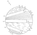
ここで図面を参照すると、図1は、周線101及び回転中心102を有する研磨パッド100を示す。CMP加工中に研磨パッド100が回転すると、研磨層(図示せず)と接する状態に保持されたウェーハ130が、外境界131及び内境界132によって画定される、幅133を有する環状の研磨トラック(又はウェーハトラック)125を描き出す。さらには、研磨パッドは、スラリー滞留時間を増し、研磨効率を高めるための溝、たとえば直線的な半径方向の溝120を有することができる。
Referring now to the drawings, FIG. 1 shows a
図1Aは、図1の研磨パッド100に関して、図1の研磨層の領域140の拡大図を示す。直線的な半径方向の溝120は、幅121を有するように示されている。幅は異なることができるが、好ましくは、幅121は、すべての溝で同じであり、各溝の長手に沿って均一である。直線的な半径方向の溝120はまた、その深さがコンディショニング及び研磨とともに徐々に減少する。直線的な半径方向の溝120の間の領域には、半径方向のミクロチャネル151、152、153及び154がある。半径方向のミクロチャネル151、152、153及び154もまた幅を有する(図示せず)。半径方向のミクロチャネルの幅及び断面積は、溝121の幅及び断面積よりも小さい。
FIG. 1A shows an enlarged view of the
半径方向のミクロチャネルは、多くのパターン及び配置を有することができる。たとえば、半径方向のミクロチャネルは、直線的な半径方向のミクロチャネル151、152及び153であってもよいし、カーブした半径方向のミクロチャネル154であってもよい。半径方向のミクロチャネルは、半径方向のミクロチャネル152のように研磨トラック全体で途切れのないものであってもよいし、セグメント化された半径方向のミクロチャネル151又は153であってもよい。半径方向のミクロチャネルセグメントは、半径方向のミクロチャネル153のように規則的に離間し、均一な長さのものであってもよいし、半径方向のミクロチャネル151のように不規則に離間し、不規則な長さのものであってもよい。さらには、半径方向のミクロチャネルは、研磨トラックの幅全体で均一な密度を有することもできるし、密度が、半径方向、周方向又は両方向に異なることもできる。一般に、ミクロチャネルの密度の増大は、除去速度の局所的増大に対応する。場合によっては、半径方向のミクロチャネル151、152、153及び154は、溝120と交差して、研磨媒体の半径方向の流れを促進し、研磨くずの除去を改善する。もう一つの任意の実施態様では、半径方向のミクロチャネル151、152、153及び154は、溝120と交差しない。
Radial microchannels can have many patterns and arrangements. For example, the radial microchannels may be straight
半径方向のミクロチャネル151、152、153及び154は、便宜上、同じ図面で示されている。本発明の研磨パッド、たとえば研磨パッド100は、溝の間の様々な領域(又は溝のない研磨パッドの様々な領域)で様々なミクロチャネルパターン及び配置を有することができるが、研磨パッドは、一つのミクロチャネルパターン及び配置しか有しないか、研磨面に対称的に配置された複数のミクロチャネル配置を有することが好ましい。
The
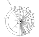
図2を参照すると、カーブした半径方向の研磨パッド200は、周線201、回転中心202ならびに外境界231及び内境界232によって画定される、幅233を有するウェーハ230の研磨トラック225を有している。研磨パッド200は、カーブした半径方向の溝220を有している。カーブした半径方向の溝220は、その第一端を研磨トラックの内境界232に有し、その第二端を周線201に有するように示されている。カーブした半径方向の溝は、ウェーハを横切る方向での除去速度を制御し、中心高速及び中心低速の研磨を得るように調節するのに特に有用である。あるいはまた、カーブした半径方向の溝220(本発明の半径方向の溝など)は、その第一端を、回転中心202の近くに有してもよいし、研磨トラック内に有してもよい。同様に、カーブした半径方向の溝220(又は他の溝)は、その第二端を、研磨トラック内に有してもよいし、外境界231の近くに有してもよい。
Referring to FIG. 2, a curved
図2Aは、図2の研磨層の領域240の拡大図でミクロチャネルを示す。カーブした半径方向の溝220は、幅221を有するように示されている。半径方向のミクロチャネル251、252、253及び254が半径方向の溝220の間の各領域に示されている。カーブした半径方向の溝220を含むいくつかの実施態様では、半径方向のミクロチャネル、すなわち直線的な半径方向のミクロチャネル251又はカーブした半径方向のミクロチャネル254が溝、すなわちカーブした半径方向の溝220と交差することが有利である。これは、スラリーの流れ及び研磨くずの除去を促進することができる。他の実施態様では、半径方向のミクロチャネルは、その大多数が半径方向の溝、すなわちカーブした半径方向のミクロチャネル252及びセグメント化され、カーブした半径方向のミクロチャネル253と交差しないようなやり方で設けられることが有利である。
FIG. 2A shows a microchannel in an enlarged view of
図3で、段状の半径方向の溝研磨パッド300は、周線301、回転中心302ならびに外境界331及び内境界332によって画定される、幅333を有する研磨トラック325を占めるウェーハ330を有している。研磨パッド300は、カーブした半径方向の溝320及び321を有している。カーブした半径方向の溝321は、その第一端を回転中心302の近くに有し、その第二端を研磨トラック325内に有している。カーブした半径方向の溝320は、その第一端を研磨トラック325内に有し、その第二端を周線301の近くに有している。カーブした半径方向の溝320及び321は、研磨媒体の研磨効率の増大を促進することができる。図は、カーブした半径方向の溝320及び321が同じパターン及び向きを有するように示すが、これらの溝は異なるパターン及び向きを有してもよい。たとえば、場合によっては、3組以上の半径方向の溝があってもよく、それらの半径方向の溝が各組の溝の間で交互に位置しなくてもよい。好ましくは、溝は、各組の溝の間で規則的なパターンで交互に位置する(2組の溝を有する研磨パッドに関して示すとおり)。カーブした半径方向の溝320及び321は、オーバラップ領域310を有するように示されているが、これは必要ではない。複数組の半径方向の溝を有する研磨パッドの場合、オーバラップ領域310は、研磨トラック325の幅333の20%よりも大きいことが好ましい。もっとも好ましくは、オーバラップ310は、研磨トラック325の幅333の50%よりも大きい。
In FIG. 3, a stepped radial
図3Aで、図3の領域340が、カーブした半径方向の溝320及び321を示す。これらの溝は、溝320と溝321とで同じであってもよいし、溝320と溝321とで異なってもよい幅322を有している。カーブした半径方向のミクロチャネル351が、カーブした半径方向の溝320及び321の間の領域に示されている。カーブした半径方向のミクロチャネル351は、交差を避けるため、概ね溝320及び321の円弧をたどる。直線状の半径方向のミクロチャネル352がカーブした半径方向の溝320及び321と交差している。最後に、カーブした半径方向のミクロチャネル353が、カーブした半径方向の溝320及び321と交差するように偏った湾曲を有している。
In FIG. 3A,
図4を参照すると、溝のない研磨パッド400が、周線401、回転中心402ならびに外境界431及び内境界432によって画定される、幅433を有する研磨トラック425を占めるウェーハ430を有している。研磨パッド400は、従来スケールの溝を有しない。コンディショニングプレート460が方向465に沿って前後に振動して、パッド400の研磨面(図示せず)をコンディショニングする。コンディショニングプレート465の表面は、好ましくは、特定のパターンに配設された切削手段(図示せず)、たとえばダイヤモンド切歯を含む。パターンは、規則的であっても不規則であってもよいし、コンディショニング面内で異なる密度の切歯を有することができる。好ましくは、コンディショニングプレートは、くさびの形を有するか、変動するストロークの長さを使用して、研磨トラック425全体でより均一なコンディショニングを提供する。
Referring to FIG. 4, a
コンディショニングパッド400をコンディショニングするためには、コンディショニングプレート460の少なくとも一部を研磨パッド400の研磨層と接触させる。そして、コンディショニングプレートを研磨パッドに対して方向465に動かす。方向465は、直線的かつ半径方向として示されているが、他の方向もまた考えられる。加えて、研磨パッドに対するコンディショニングプレートの動きは振動として示されているが、一方向の動きもまた考えられる。コンディショニングプレートは、従来の単軸手段、たとえばピボットアームもしくはスライド又は従来の多軸手段、たとえばx−yスライドもしくは伸縮ピボットアームによって制御することができる。コンディショニングプレートの動きはまた、研磨パッド400の研磨層との断続的な接触を可能にするため、垂直運動を含むこともできる。本発明の要件を満たすためには、研磨パッド400の研磨層に対して平行な面におけるコンディショニングプレート460の運動が研磨パッド400の線速度に対して高速であることが不可欠である。
In order to condition the
図4Aを参照すると、任意のミクロチャネルパターンは、平行な半径方向のミクロチャネル451、半径方向のミクロチャネル452、カーブした半径方向のミクロチャネル453、段状又はバイパスの半径方向のミクロチャネル454及びセグメント化された半径方向のミクロチャネル455を含む。加えて、これらのミクロチャネルは、研磨媒体の流れを優先的に方向付けするように設計された他のパターン及びパターン密度を有することができる。これらのミクロチャネルは、研磨媒体の流れを小さなスケールで制御する利点を有する。たとえば、カーブした半径方向のミクロチャネルは、ウェーハ均一さ、たとえば中心高速又は中心低速問題を修正することができ、段状の半径方向のミクロチャネルは、研磨媒体の効率を高めることができる。
Referring to FIG. 4A, any microchannel pattern may include parallel
あるいはまた、コンディショニングプレートは、回転可能なディスクであってもよい。コンディショニングディスクは、平らであってもよいし、カーブしていてもよいし(お椀形又は平らなディスクのエッジを使用することができる)、複数の平らな面を異なる平面に有してもよい。たとえば、コンディショニングプレートは、コンディショニングプレートのコンディショニング面の少なくとも一部が研磨パッドの研磨面と接触した状態で、研磨パッドが位置する平面とは異なる平面でディスクを回転させることによって半径方向のミクロチャネルを形成するために使用することもできる。加えて、より長いコンディショニング行程及びより幅広いコンディショニングプレートがそれぞれ平行なミクロ溝の割合の増大につながる。好ましくは、コンディショニング加工は、より幅が狭いコンディショニングプレートを用いる高速行程の回数増に依存して、半径方向のミクロチャネルの割合を増大させる。これらの行程は、優先的には、研磨トラック内のミクロチャネルの分布を均等にするため、パッドの回転速度とは非同期的である。加えて、コンディショニングプレートのピボットアームをパッドの回転方向に弧状に曲げると、ミクロチャネルの半径方向の向きをさらに改善することができる。 Alternatively, the conditioning plate may be a rotatable disk. Conditioning discs may be flat, curved (can use bowl or flat disc edges), and have multiple flat surfaces in different planes. . For example, a conditioning plate can create radial microchannels by rotating a disk in a plane different from the plane in which the polishing pad is located, with at least a portion of the conditioning plate's conditioning surface in contact with the polishing surface of the polishing pad. It can also be used to form. In addition, longer conditioning strokes and wider conditioning plates each lead to an increased proportion of parallel microgrooves. Preferably, the conditioning process increases the proportion of radial microchannels depending on the number of high speed strokes using a narrower conditioning plate. These strokes are preferentially asynchronous with the rotational speed of the pad to equalize the distribution of microchannels within the polishing track. In addition, the radial orientation of the microchannel can be further improved if the conditioning plate pivot arm is bent in an arc in the direction of pad rotation.
もう一つの代替方法は、コンディショニングディスクを使用せずに、たとえば研磨パッドの研磨面をブレード、たとえばナイフ又はフライス加工ツール、たとえばCNCツールで切り目を入れることによって研磨パッドをコンディショニングする方法である。加えて、ミクロチャネルは、場合によっては、研磨層の研磨面をレーザ、高圧液体もしくは気体ジェット又は他の手段で除去又は切り目を入れることによって設けられる。もっとも好ましくは、研磨加工中、連続的にインサイチュでのコンディショニングが起こる。加えて、いくつかの任意の実施態様では、半径方向のコンディショニングを、円形ディスク、たとえば円形ダイヤモンドディスクを回転させることに関連する従来のコンディショニングと重ね合わせることも可能である。しかし、好ましくは、ミクロチャネルの大多数がウェーハトラック中で主として半径方向の向きを有して溝パターン転写効果を減らす。 Another alternative is to condition the polishing pad without using a conditioning disk, for example by cutting the polishing surface of the polishing pad with a blade, such as a knife or milling tool, such as a CNC tool. In addition, microchannels are optionally provided by removing or nicking the polishing surface of the polishing layer with a laser, high pressure liquid or gas jet, or other means. Most preferably, in-situ conditioning occurs continuously during the polishing process. In addition, in some optional embodiments, radial conditioning can be superimposed with conventional conditioning associated with rotating a circular disk, eg, a circular diamond disk. However, preferably the majority of the microchannels have a predominantly radial orientation in the wafer track to reduce the groove pattern transfer effect.
Claims (1)
b)前記研磨層中の、前記環状研磨トラックの幅の範囲内にある複数の半径方向のミクロチャネルであって、前記半径方向の溝の平均断面積の10分の1以下である平均断面積を有し、大多数が主として半径方向の向きを有する半径方向のミクロチャネル
を含み、
前記研磨層がカーブした半径方向の溝を含み、前記半径方向のミクロチャネルがカーブした半径方向のミクロチャネルを含む、磁性基材、光学基材及び半導体基材の少なくとも一つを研磨するのに有用な研磨パッド。 a) a polishing layer having a center of rotation, concentric with the center of rotation and including an annular polishing track having a width, wherein the width of the annular polishing track includes a groove in the radial direction; A polishing layer in which the directional grooves have an average cross-sectional area; and b) a plurality of radial microchannels in the polishing layer that are within the width of the annular polishing track, the radius Comprising a radial microchannel having an average cross-sectional area that is less than or equal to one-tenth of the average cross-sectional area of the directional groove, the majority having a predominantly radial orientation ;
For polishing at least one of a magnetic substrate, an optical substrate, and a semiconductor substrate, wherein the polishing layer includes a curved radial groove and the radial microchannel includes a curved radial microchannel. Useful polishing pad.
Applications Claiming Priority (2)
| Application Number | Priority Date | Filing Date | Title |
|---|---|---|---|
| US67046605P | 2005-04-12 | 2005-04-12 | |
| US60/670,466 | 2005-04-12 |
Publications (3)
| Publication Number | Publication Date |
|---|---|
| JP2006289605A JP2006289605A (en) | 2006-10-26 |
| JP2006289605A5 JP2006289605A5 (en) | 2009-05-07 |
| JP5089073B2 true JP5089073B2 (en) | 2012-12-05 |
Family
ID=37054983
Family Applications (1)
| Application Number | Title | Priority Date | Filing Date |
|---|---|---|---|
| JP2006109276A Active JP5089073B2 (en) | 2005-04-12 | 2006-04-12 | Radially offset polishing pad |
Country Status (7)
| Country | Link |
|---|---|
| US (1) | US7255633B2 (en) |
| JP (1) | JP5089073B2 (en) |
| KR (1) | KR101279819B1 (en) |
| CN (1) | CN100515685C (en) |
| DE (1) | DE102006016312B4 (en) |
| FR (1) | FR2884164B1 (en) |
| TW (1) | TWI372093B (en) |
Families Citing this family (31)
| Publication number | Priority date | Publication date | Assignee | Title |
|---|---|---|---|---|
| US20020068516A1 (en) * | 1999-12-13 | 2002-06-06 | Applied Materials, Inc | Apparatus and method for controlled delivery of slurry to a region of a polishing device |
| JP2008062367A (en) * | 2006-09-11 | 2008-03-21 | Nec Electronics Corp | Polishing device, polishing pad, and polishing method |
| TWI455795B (en) * | 2007-10-18 | 2014-10-11 | Iv Technologies Co Ltd | Polishing pad and polishing method |
| US7927092B2 (en) * | 2007-12-31 | 2011-04-19 | Corning Incorporated | Apparatus for forming a slurry polishing pad |
| US9180570B2 (en) | 2008-03-14 | 2015-11-10 | Nexplanar Corporation | Grooved CMP pad |
| US9117870B2 (en) * | 2008-03-27 | 2015-08-25 | Lam Research Corporation | High throughput cleaner chamber |
| WO2009139401A1 (en) * | 2008-05-16 | 2009-11-19 | 東レ株式会社 | Polishing pad |
| TWI449597B (en) * | 2008-07-09 | 2014-08-21 | Iv Technologies Co Ltd | Polishing pad and method of forming the same |
| TWI535527B (en) * | 2009-07-20 | 2016-06-01 | 智勝科技股份有限公司 | Polishing method, polishing pad and polishing system |
| JP5544124B2 (en) * | 2009-08-18 | 2014-07-09 | 富士紡ホールディングス株式会社 | Polishing pad |
| US8562272B2 (en) | 2010-02-16 | 2013-10-22 | Lam Research Corporation | Substrate load and unload mechanisms for high throughput |
| US8893642B2 (en) | 2010-03-24 | 2014-11-25 | Lam Research Corporation | Airflow management for low particulate count in a process tool |
| US8282698B2 (en) * | 2010-03-24 | 2012-10-09 | Lam Research Corporation | Reduction of particle contamination produced by moving mechanisms in a process tool |
| JP5839163B2 (en) * | 2010-07-12 | 2016-01-06 | Jsr株式会社 | Chemical mechanical polishing pad and chemical mechanical polishing method |
| US20140054266A1 (en) * | 2012-08-24 | 2014-02-27 | Wiechang Jin | Compositions and methods for selective polishing of platinum and ruthenium materials |
| US9522454B2 (en) * | 2012-12-17 | 2016-12-20 | Seagate Technology Llc | Method of patterning a lapping plate, and patterned lapping plates |
| EP3237146A1 (en) * | 2014-12-22 | 2017-11-01 | 3M Innovative Properties Company | Abrasive articles with removable abrasive member and methods of separating and replacing thereof |
| CN108883515A (en) * | 2016-03-24 | 2018-11-23 | 应用材料公司 | The pulvinulus of veining for chemically mechanical polishing |
| US10875146B2 (en) * | 2016-03-24 | 2020-12-29 | Rohm And Haas Electronic Materials Cmp Holdings | Debris-removal groove for CMP polishing pad |
| US10625393B2 (en) | 2017-06-08 | 2020-04-21 | Rohm And Haas Electronic Materials Cmp Holdings, Inc. | Chemical mechanical polishing pads having offset circumferential grooves for improved removal rate and polishing uniformity |
| US10857648B2 (en) | 2017-06-14 | 2020-12-08 | Rohm And Haas Electronic Materials Cmp Holdings | Trapezoidal CMP groove pattern |
| US10777418B2 (en) * | 2017-06-14 | 2020-09-15 | Rohm And Haas Electronic Materials Cmp Holdings, I | Biased pulse CMP groove pattern |
| US10586708B2 (en) | 2017-06-14 | 2020-03-10 | Rohm And Haas Electronic Materials Cmp Holdings, Inc. | Uniform CMP polishing method |
| US10857647B2 (en) | 2017-06-14 | 2020-12-08 | Rohm And Haas Electronic Materials Cmp Holdings | High-rate CMP polishing method |
| US10861702B2 (en) | 2017-06-14 | 2020-12-08 | Rohm And Haas Electronic Materials Cmp Holdings | Controlled residence CMP polishing method |
| US10654146B2 (en) | 2018-01-23 | 2020-05-19 | Seagate Technology Llc | One or more charging members used in the manufacture of a lapping plate, and related apparatuses and methods of making |
| CN110039380B (en) * | 2019-04-11 | 2020-12-01 | 上海理工大学 | Magnetic composite fluid polishing device for polishing periodic micro-groove structure |
| CN112720282B (en) * | 2020-12-31 | 2022-04-08 | 湖北鼎汇微电子材料有限公司 | Polishing pad |
| WO2023013576A1 (en) * | 2021-08-04 | 2023-02-09 | 株式会社クラレ | Polishing pad |
| CN114770371B (en) * | 2022-03-10 | 2023-08-25 | 宁波赢伟泰科新材料有限公司 | Polishing pad with high polishing solution use efficiency |
| CN114918824A (en) * | 2022-06-29 | 2022-08-19 | 万华化学集团电子材料有限公司 | Polishing pad with radial micro-grooves |
Family Cites Families (24)
| Publication number | Priority date | Publication date | Assignee | Title |
|---|---|---|---|---|
| US5081051A (en) * | 1990-09-12 | 1992-01-14 | Intel Corporation | Method for conditioning the surface of a polishing pad |
| US5216843A (en) * | 1992-09-24 | 1993-06-08 | Intel Corporation | Polishing pad conditioning apparatus for wafer planarization process |
| US5456627A (en) | 1993-12-20 | 1995-10-10 | Westech Systems, Inc. | Conditioner for a polishing pad and method therefor |
| US5785585A (en) * | 1995-09-18 | 1998-07-28 | International Business Machines Corporation | Polish pad conditioner with radial compensation |
| US5611943A (en) * | 1995-09-29 | 1997-03-18 | Intel Corporation | Method and apparatus for conditioning of chemical-mechanical polishing pads |
| JP3042593B2 (en) * | 1995-10-25 | 2000-05-15 | 日本電気株式会社 | Polishing pad |
| US5938507A (en) | 1995-10-27 | 1999-08-17 | Applied Materials, Inc. | Linear conditioner apparatus for a chemical mechanical polishing system |
| US5645469A (en) * | 1996-09-06 | 1997-07-08 | Advanced Micro Devices, Inc. | Polishing pad with radially extending tapered channels |
| US5885147A (en) * | 1997-05-12 | 1999-03-23 | Integrated Process Equipment Corp. | Apparatus for conditioning polishing pads |
| US5916010A (en) * | 1997-10-30 | 1999-06-29 | International Business Machines Corporation | CMP pad maintenance apparatus and method |
| US6027659A (en) * | 1997-12-03 | 2000-02-22 | Intel Corporation | Polishing pad conditioning surface having integral conditioning points |
| JP2001001253A (en) * | 1999-06-21 | 2001-01-09 | Toray Ind Inc | Abrasive cloth |
| US6306008B1 (en) * | 1999-08-31 | 2001-10-23 | Micron Technology, Inc. | Apparatus and method for conditioning and monitoring media used for chemical-mechanical planarization |
| US6626743B1 (en) * | 2000-03-31 | 2003-09-30 | Lam Research Corporation | Method and apparatus for conditioning a polishing pad |
| JP2003535462A (en) | 2000-05-31 | 2003-11-25 | コーニンクレッカ フィリップス エレクトロニクス エヌ ヴィ | Polishing method and apparatus for manufacturing semiconductors and integrated circuits |
| JP2002100592A (en) * | 2000-09-20 | 2002-04-05 | Rodel Nitta Co | Abrasive pad |
| US6767427B2 (en) * | 2001-06-07 | 2004-07-27 | Lam Research Corporation | Apparatus and method for conditioning polishing pad in a chemical mechanical planarization process |
| JP2003145413A (en) * | 2001-10-31 | 2003-05-20 | Applied Materials Inc | Polishing pad |
| JP2003303793A (en) * | 2002-04-12 | 2003-10-24 | Hitachi Ltd | Polishing equipment and method for manufacturing semiconductor device |
| JP2004167605A (en) * | 2002-11-15 | 2004-06-17 | Rodel Nitta Co | Polishing pad and polishing device |
| US6976907B2 (en) * | 2003-01-10 | 2005-12-20 | Intel Corporation | Polishing pad conditioning |
| WO2005023487A1 (en) * | 2003-08-29 | 2005-03-17 | Toho Engineering Kabushiki Kaisha | Polishing pad, and method and apparatus for producing same |
| US7591713B2 (en) * | 2003-09-26 | 2009-09-22 | Shin-Etsu Handotai Co., Ltd. | Polishing pad, method for processing polishing pad, and method for producing substrate using it |
| US6843711B1 (en) * | 2003-12-11 | 2005-01-18 | Rohm And Haas Electronic Materials Cmp Holdings, Inc | Chemical mechanical polishing pad having a process-dependent groove configuration |
-
2006
- 2006-03-17 KR KR1020060025061A patent/KR101279819B1/en active IP Right Grant
- 2006-03-29 US US11/392,373 patent/US7255633B2/en active Active
- 2006-04-06 DE DE102006016312.5A patent/DE102006016312B4/en not_active Expired - Fee Related
- 2006-04-10 TW TW095112634A patent/TWI372093B/en active
- 2006-04-11 FR FR0651303A patent/FR2884164B1/en not_active Expired - Fee Related
- 2006-04-11 CN CNB2006100747763A patent/CN100515685C/en not_active Expired - Fee Related
- 2006-04-12 JP JP2006109276A patent/JP5089073B2/en active Active
Also Published As
| Publication number | Publication date |
|---|---|
| FR2884164A1 (en) | 2006-10-13 |
| CN1846940A (en) | 2006-10-18 |
| FR2884164B1 (en) | 2014-04-11 |
| DE102006016312A1 (en) | 2006-10-19 |
| KR20060108211A (en) | 2006-10-17 |
| CN100515685C (en) | 2009-07-22 |
| JP2006289605A (en) | 2006-10-26 |
| TWI372093B (en) | 2012-09-11 |
| KR101279819B1 (en) | 2013-06-28 |
| US7255633B2 (en) | 2007-08-14 |
| TW200642797A (en) | 2006-12-16 |
| DE102006016312B4 (en) | 2018-10-31 |
| US20060229002A1 (en) | 2006-10-12 |
Similar Documents
| Publication | Publication Date | Title |
|---|---|---|
| JP5089073B2 (en) | Radially offset polishing pad | |
| JP3823086B2 (en) | Polishing pad and polishing method | |
| TWI788070B (en) | Polishing articles and integrated system for manufacturing chemical mechanical polishing articles | |
| KR101507611B1 (en) | interpenetrating network for chemical mechanical polishing | |
| US6899602B2 (en) | Porous polyurethane polishing pads | |
| JP3072526B2 (en) | Polishing pad and method of using the same | |
| KR101539462B1 (en) | Layered-filament lattice for chemical mechanical polishing | |
| US6500053B2 (en) | Polishing pads and methods relating thereto | |
| US7458885B1 (en) | Chemical mechanical polishing pad and methods of making and using same | |
| KR101601281B1 (en) | High-rate polishing method | |
| US7226345B1 (en) | CMP pad with designed surface features | |
| US20070173187A1 (en) | Chemical mechanical polishing pad with micro-holes | |
| JP2007180550A (en) | Multi-layered polishing pad with improved defectivity and its manufacture method | |
| KR20070082575A (en) | Three-dimensional network for chemical mechanical polishing | |
| US20220226963A1 (en) | Chemical mechanical planarization tools, and related pads for chemical mechanical planarization tools | |
| JP2647046B2 (en) | Polishing cloth and polishing method | |
| JP2008187086A (en) | Chemical mechanical polishing pad |
Legal Events
| Date | Code | Title | Description |
|---|---|---|---|
| A521 | Written amendment |
Free format text: JAPANESE INTERMEDIATE CODE: A523 Effective date: 20090325 |
|
| A621 | Written request for application examination |
Free format text: JAPANESE INTERMEDIATE CODE: A621 Effective date: 20090325 |
|
| A131 | Notification of reasons for refusal |
Free format text: JAPANESE INTERMEDIATE CODE: A131 Effective date: 20110920 |
|
| A601 | Written request for extension of time |
Free format text: JAPANESE INTERMEDIATE CODE: A601 Effective date: 20111219 |
|
| A602 | Written permission of extension of time |
Free format text: JAPANESE INTERMEDIATE CODE: A602 Effective date: 20111222 |
|
| A131 | Notification of reasons for refusal |
Free format text: JAPANESE INTERMEDIATE CODE: A131 Effective date: 20120605 |
|
| A521 | Written amendment |
Free format text: JAPANESE INTERMEDIATE CODE: A523 Effective date: 20120809 |
|
| TRDD | Decision of grant or rejection written | ||
| A01 | Written decision to grant a patent or to grant a registration (utility model) |
Free format text: JAPANESE INTERMEDIATE CODE: A01 Effective date: 20120828 |
|
| A01 | Written decision to grant a patent or to grant a registration (utility model) |
Free format text: JAPANESE INTERMEDIATE CODE: A01 |
|
| A61 | First payment of annual fees (during grant procedure) |
Free format text: JAPANESE INTERMEDIATE CODE: A61 Effective date: 20120911 |
|
| FPAY | Renewal fee payment (event date is renewal date of database) |
Free format text: PAYMENT UNTIL: 20150921 Year of fee payment: 3 |
|
| R150 | Certificate of patent or registration of utility model |
Ref document number: 5089073 Country of ref document: JP Free format text: JAPANESE INTERMEDIATE CODE: R150 Free format text: JAPANESE INTERMEDIATE CODE: R150 |