JP5085984B2 - Pneumatic tire - Google Patents
Pneumatic tire Download PDFInfo
- Publication number
- JP5085984B2 JP5085984B2 JP2007156715A JP2007156715A JP5085984B2 JP 5085984 B2 JP5085984 B2 JP 5085984B2 JP 2007156715 A JP2007156715 A JP 2007156715A JP 2007156715 A JP2007156715 A JP 2007156715A JP 5085984 B2 JP5085984 B2 JP 5085984B2
- Authority
- JP
- Japan
- Prior art keywords
- groove
- narrow groove
- block
- corner
- pneumatic tire
- Prior art date
- Legal status (The legal status is an assumption and is not a legal conclusion. Google has not performed a legal analysis and makes no representation as to the accuracy of the status listed.)
- Expired - Fee Related
Links
Images


Description
本発明は、トレッドにブロックパターンを備えた空気入りタイヤにかかり、特に、摩耗末期までトレッドの均一な摩耗状態を維持するため、ブロックにおけるヒール・アンド・トゥ摩耗を抑制することのできる空気入りタイヤに関する。 The present invention relates to a pneumatic tire having a block pattern on a tread, and in particular, a pneumatic tire capable of suppressing heel and toe wear in a block in order to maintain a uniform wear state of the tread until the end of wear. About.
ブロックパターンを有する空気入りタイヤでは、ブロックにヒール・アンド・トゥ摩耗を発生する。
ヒール・アンド・トゥ摩耗を抑制するために、例えば、特許文献1には、ショルダーブロックのヒール・アンド・トゥ摩耗の進展を抑制するために、接地端より軸方向外側に離れた位置に周方向に延びる細溝を配置することが記載されている。
In order to suppress the heel and toe wear, for example, in Patent Document 1, in order to suppress the progress of the heel and toe wear of the shoulder block, the circumferential direction is positioned away from the ground contact end in the axial direction. It is described that a narrow groove extending in the direction is arranged.
しかしながら、上記従来の方法では、トレッド幅方向最外側のブロックである、ショルダーのヒール・アンド・トゥ摩耗を抑制することはできるが、周方向主溝間のブロック、即ちショルダーブロックよりもタイヤ幅方向内側に位置するブロックに発生するヒール・アンド・トゥ摩耗を抑制することが出来なかった。
また、走行時、ブロックには周方向の力のみならず横力も入力する。特に、横力が作用する場合には、ブロックの蹴り出し側のトレッド幅方向最外側の角部から摩耗し始めて、次第にブロックの踏み込み側に向かって斜め内側に偏摩耗が進展する。
従来のヒール・アンド・トゥ摩耗を抑制する技術では、蹴り出し端からの摩耗が周方向に沿って踏み込み側へ進展する摩耗を抑制することを目的としていたため、ブロックの蹴り出し側のトレッド幅方向最外側の角部から摩耗し始めて、次第にブロックの踏み込み側に向かって斜め内側に偏摩耗が進展するという、周方向に対して斜め方向に摩耗が進展するヒール・アンド・トゥ摩耗を効果的に抑制することが出来なかった。
However, the conventional method can suppress the heel and toe wear of the shoulder, which is the outermost block in the tread width direction, but the block between the circumferential main grooves, that is, the tire width direction than the shoulder block. Heel and toe wear that occurs on the inner block could not be suppressed.
In addition, not only the circumferential force but also lateral force is input to the block during running. In particular, when a lateral force is applied, wear starts from the outermost corner in the tread width direction on the kicking side of the block, and uneven wear gradually progresses inward toward the stepping side of the block.
The conventional technology for suppressing heel-and-toe wear was designed to suppress wear from the kicked-out edge that progresses toward the stepping side along the circumferential direction, so the tread width on the kicked-out side of the block Effective heel-and-toe wear that begins to wear from the outermost corner in the direction and gradually progresses toward the stepping side of the block. Could not be suppressed.
本発明は、上記問題を解決すべく成されたもので、ブロックの蹴り出し側のトレッド幅方向最外側の角部から摩耗し始めて、次第にブロックの踏み込み側に向かって斜め内側に偏摩耗が進展する形態のヒール・アンド・トゥ摩耗を効果的に抑制可能な空気入りタイヤの提供を目的とする。 The present invention has been made to solve the above-mentioned problem, and begins to wear from the outermost corner in the tread width direction on the kicking side of the block and gradually develops uneven wear diagonally inward toward the stepping side of the block. An object of the present invention is to provide a pneumatic tire capable of effectively suppressing heel-and-toe wear.
発明者がヒール・アンド・トゥ摩耗の発生過程を詳細に調査し、種々検討した結果、ブロックに発生するヒール・アンド・トゥ摩耗は、特に横力が作用する場合に、ブロックの蹴り出し側のトレッド幅方向最外側の端の角部から摩耗し始めて、次第にブロックの踏み込み側に向かって斜め内側に偏摩耗が進展して行くが、角部の近傍に、角部の二等分線に対して交差する方向に延びる細溝を形成し、この細溝の位置等を最適に設定することで、該偏摩耗の進展を効果的に抑制できることを見出した。 As a result of detailed investigations and various studies by the inventor on the generation process of the heel and toe wear, the heel and toe wear generated on the block is particularly difficult when the lateral force is applied. It begins to wear from the corner of the outermost edge in the tread width direction, and then gradually wears inwardly toward the stepping side of the block, but in the vicinity of the corner, against the bisector of the corner It has been found that the development of the uneven wear can be effectively suppressed by forming narrow grooves extending in the intersecting direction and setting the positions of the narrow grooves and the like optimally.
請求項1に記載の発明は、周方向に延びる複数の周方向溝と、前記周方向溝と交差する方向に延びる複数のラグ溝とで区画された複数のブロックをトレッドに備えた空気入りタイヤであって、前記ブロックの蹴り出し側でかつトレッド幅方向最外側の第1の角部側に、前記第1の角部を構成する2辺の二等分線に対して、90°±20°の角度で交差し、かつ前記周方向溝、及び前記ラグ溝よりも溝幅が狭くかつ溝深さが浅く設定された第1の細溝を形成し、前記2等分線上で計測する前記第1の角部から前記第1の細溝までの距離を5mm以上10mm以下に設定する、ことを特徴としている。 The invention according to claim 1 is a pneumatic tire in which a tread includes a plurality of blocks defined by a plurality of circumferential grooves extending in the circumferential direction and a plurality of lug grooves extending in a direction intersecting the circumferential groove. 90 ° ± 20 with respect to the bisector of the two sides constituting the first corner on the kicking side of the block and on the first corner on the outermost side in the tread width direction The first narrow groove intersecting at an angle of 0 ° and having a groove width narrower than that of the lug groove and a shallow groove depth is formed, and measurement is performed on the bisector. The distance from the first corner to the first narrow groove is set to 5 mm or more and 10 mm or less.
次に、請求項1に記載の空気入りタイヤの作用を説明する。
例えば、車両がコーナリングした場合、旋回の半径方向外側の空気入りタイヤのトレッドのなかでも、タイヤ赤道面よりも旋回の半径方向外側に位置するブロックに大きな横力(車両外側からタイヤ赤道面方向)が作用する。タイヤ周方向の力と横力とがブロックに作用すると、ブロックには、蹴り出し側で、かつトレッド幅方向の最も外側の第1の角部から斜め踏み込み側(ブロック中央側)へ向けて偏摩耗が進展しようとする。
Next, the operation of the pneumatic tire according to claim 1 will be described.
For example, when the vehicle corners, a large lateral force is exerted on the block located radially outward of the turn from the tire equator plane (from the vehicle outer side to the tire equator plane) in the tread of the pneumatic tire on the radially outer side of the turn. Works. When force in the tire circumferential direction and lateral force act on the block, the block is biased toward the side of the kick-out and from the outermost first corner in the tread width direction toward the stepping-in side (center side of the block). Wear is about to progress.
ブロックの蹴り出し側でかつトレッド幅方向最外側の第1の角部側に、第1の角部を構成する2辺の二等分線に対して、90°±20°の角度で交差し、かつ周方向溝、及びラグ溝よりも溝幅が狭くかつ溝深さが浅く設定された第1の細溝を形成することで、第1の角部側で発生した偏摩耗が、ブロックの踏み込み側に向かって斜め内側(ブロック中央側)に進展することを抑制できる。 It intersects at the angle of 90 ° ± 20 ° with the bisector of the two sides that constitute the first corner on the block kicking side and the first corner on the outermost side in the tread width direction. In addition, by forming the first narrow groove having a groove width narrower than that of the circumferential groove and the lug groove and having a shallow groove depth , uneven wear occurring on the first corner side is reduced. It can suppress progressing diagonally inside (block center side) toward the stepping side.
なお、第1の細溝の方向が、二等分線に対して90°±20°より外れると、第1の角部と第1の細溝との間の三角形部分における3つの角部分の内の何れかの角部分の角度が小さくなり過ぎ、剛性不足によってブロック欠けの原因となる。 When the direction of the first narrow groove deviates from 90 ° ± 20 ° with respect to the bisector, three corner portions of the triangular portion between the first corner portion and the first narrow groove The angle of any one of the corner portions becomes too small, and lack of rigidity causes block missing.
また、二等分線上で計測する第1の角部から第1の細溝までの距離が5mm未満の場合、ブロック剛性が低い部分(第1の角部と第1の細溝との間の三角形部分)が欠け易くなる。
一方、二等分線上で計測する第1の角部から第1の細溝までの距離が10mmを越える場合、第1の角部から第1の細溝までの距離が長くなりすぎ、ヒール・アンド・トゥ摩耗の進展を抑制できなくなる。
In addition, when the distance from the first corner portion measured on the bisector to the first narrow groove is less than 5 mm, the block rigidity is low (between the first corner portion and the first narrow groove). (Triangle part) becomes easy to chip.
On the other hand, when the distance from the first corner to the first narrow groove measured on the bisector exceeds 10 mm, the distance from the first corner to the first narrow groove becomes too long, It becomes impossible to suppress the progress of the to-to-wear.
請求項2に記載の発明は、請求項1に記載の空気入りタイヤにおいて、前記ブロックの踏み込み側でかつトレッド幅方向最外側の第2の角部側に、前記第2の角部を構成する2辺の二等分線に対して、90°±20°の角度で交差し、かつ前記周方向溝、及び前記ラグ溝よりも溝幅が狭くかつ溝深さが浅く設定された第2の細溝を形成し、前記2等分線上で計測する前記第2の角部から前記第2の細溝までの距離を5mm以上10mm以下に設定する、ことを特徴としている。 According to a second aspect of the present invention, in the pneumatic tire according to the first aspect, the second corner portion is configured on the stepping side of the block and on the second corner portion side on the outermost side in the tread width direction. A second line that intersects the bisector of two sides at an angle of 90 ° ± 20 °, is set to have a narrower groove width and a shallower groove depth than the circumferential groove and the lug groove. A narrow groove is formed, and a distance from the second corner portion measured on the bisector to the second narrow groove is set to 5 mm or more and 10 mm or less.
次に、請求項2に記載の空気入りタイヤの作用を説明する。
空気入りタイヤに回転方向の指定があれば、細溝は、ブロックの蹴り出し側のトレッド幅方向最外側の第1の角部側にのみ形成すれば良いが、回転方向が指定されない空気入りタイヤの場合、踏み込み側のトレッド幅方向最外側の第2の角部にも細溝(第2の細溝)を形成すれば、何れの回転方向であっても、ブロックのヒール・アンド・トゥ摩耗の進展を抑制できる。
Next, the operation of the pneumatic tire according to claim 2 will be described.
If the pneumatic tire has a designation of the rotational direction, the narrow groove may be formed only on the outermost first corner side in the tread width direction on the kicking side of the block, but the pneumatic tire does not designate the rotational direction. In this case, if a narrow groove (second narrow groove) is formed in the outermost second corner in the tread width direction on the stepping side, the heel and toe wear of the block is possible in any rotation direction. Can be suppressed.
請求項3に記載の発明は、請求項1または請求項2に記載の空気入りタイヤにおいて、前記第1の細溝、及び前記第2の細溝は、溝幅が2〜4mmの範囲内に設定されている、ことを特徴としている。 The invention according to claim 3 is the pneumatic tire according to claim 1 or 2, wherein the first narrow groove and the second narrow groove have a groove width in a range of 2 to 4 mm. It is characterized by being set.
次に、請求項3に記載の空気入りタイヤの作用を説明する。
細溝の溝幅が2mm未満では、接地時に細溝が閉じてしまい、ブロック剛性が低い部分(細溝より角部側の領域)とブロック剛性の高い部分(細溝よりブロック中央側)とが接触することでヒール・アンド・トゥ摩耗が進展する場合がある。
Next, the operation of the pneumatic tire according to claim 3 will be described.
If the groove width of the narrow groove is less than 2 mm, the narrow groove is closed at the time of ground contact, and a portion with low block rigidity (region on the corner side from the narrow groove) and a portion with high block rigidity (center side of the block from the narrow groove) are formed. Healing and toe wear may develop due to contact.
一方、細溝の溝幅が4mmを越えると、ブロックの接地面積が小さくなり過ぎて、逆に偏摩耗を助長する可能性がある。 On the other hand, if the groove width of the narrow groove exceeds 4 mm, the ground contact area of the block becomes too small, and on the contrary, there is a possibility of promoting uneven wear.
請求項4に記載の発明は、請求項1〜3の何れか1項に記載の空気入りタイヤにおいて、前記第1の細溝、及び前記第2の細溝は、溝深さが2〜4mmの範囲内に設定されている、ことを特徴としている。 According to a fourth aspect of the present invention, in the pneumatic tire according to any one of the first to third aspects, the first narrow groove and the second narrow groove have a groove depth of 2 to 4 mm. It is set within the range of.
次に、請求項4に記載の空気入りタイヤの作用を説明する。
細溝の溝深さが2mm未満では、ヒール・アンド・トゥ摩耗の進展を抑制する前に細溝が消滅してしまう。
一方、細溝の溝深さが4mmを越えると、ブロック剛性が低い部分(細溝より角部側の領域)が欠け易くなる。
Next, the operation of the pneumatic tire according to claim 4 will be described.
If the groove depth of the narrow groove is less than 2 mm, the narrow groove disappears before the progress of the heel and toe wear is suppressed.
On the other hand, if the groove depth of the narrow groove exceeds 4 mm, a portion having a low block rigidity (region on the corner side from the narrow groove) tends to be lost.
以上説明したように本発明の空気入りタイヤは上記構成としたので、ブロックに発生するヒール・アンド・トゥ摩耗の中でも、特に、横力が作用する場合の、ブロックの蹴り出し側のトレッド幅方向最外側の端の角部側からブロックの踏み込み側に向かって斜め内側に進展する偏摩耗を効果的に抑制することができる。 As described above, since the pneumatic tire of the present invention has the above-described configuration, the tread width direction on the kick-out side of the block, particularly when the lateral force is applied, among the heel and toe wear generated in the block. It is possible to effectively suppress uneven wear that progresses obliquely inward from the corner side of the outermost end toward the stepping side of the block.
したがって、車両の車輪の中でも、横力が作用する頻度が大きい、例えば、操舵輪に本発明の空気入りタイヤを用いることが特に効果的である。 Therefore, it is particularly effective to use the pneumatic tire of the present invention for the steered wheels, for example, in which the lateral force acts frequently among the wheels of the vehicle.
以下、図面を参照して本発明の実施の形態の一例を詳細に説明する。
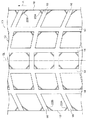
図1に示すように、本発明の一実施形態に係る空気入りタイヤ(例えば、タイヤサイズ:11R22.5)10のトレッド12には、タイヤ周方向に延びる複数本の周方向溝14と、これら周方向溝14と交差する方向に延びる複数本のラグ溝16とで区画された複数のブロック18が区画されている。なお、図1中、矢印A方向は空気入りタイヤ10の回転方向である。
Hereinafter, an example of an embodiment of the present invention will be described in detail with reference to the drawings.
As shown in FIG. 1, a
本実施形態のラグ溝16は、タイヤ赤道面CL側がトレッド端側よりもタイヤ回転方向側となるようにタイヤ幅方向に対して傾斜しており、タイヤ赤道面CLの右側のラグ溝16と左側のラグ溝16とでは傾斜方向が反対方向となっている。したがって、本実施形態のブロック18は、トレッド平面視で平行四辺形を呈している。
The
図2に示すように、ブロック18には、蹴り出し側(矢印A方向とは反対側)で、かつタイヤ赤道面CLからトレッド幅方向最外側の第1の角部18A側に、第1の角部18Aの二等分線LAに対して、90°±20°の角度θAで交差し、かつ周方向溝14、及びラグ溝16よりも溝幅が狭くかつ溝深さが浅く設定された第1の細溝22Aが形成されている。なお、本実施形態において、第1の角部18Aから第1の細溝22Aまでの二等分線LA上で計測する距離DAが、5mm以上10mm以下に設定されている。
As shown in FIG. 2, the
また、各ブロック18には、踏み込み側(矢印A方向側)のトレッド幅方向最外側の第2の角部18B側に、第2の角部18Bの二等分線LBに対して、90°±20°の角度で交差し、かつ周方向溝14、及びラグ溝16よりも溝幅が狭くかつ溝深さが浅く設定された第2の細溝22Bが形成されている。なお、本実施形態において、第2の角部18Bから第2の細溝22Bまでの二等分線LB上で計測する距離DBが、5mm以上10mm以下に設定されている。
なお、第1の細溝22A、及び第2の細溝22Bは、各々の端部がブロック端(周方向溝14またはラグ溝16)に接続されている。
Each
Note that the first
なお、本実施形態では、周方向溝14は、溝幅が10.0mm、溝深さが16.2mm、ラグ溝16は、溝幅が9.0mm、溝深さが16.2mmである。
ここで、第1の細溝22A、及び第2の細溝22Bの溝幅は、2〜4mmの範囲内が好ましい。
また、第1の細溝22A、及び第2の細溝22Bの溝深は、2〜4mmの範囲内が好ましい。
また、第1の細溝22A、及び第2の細溝22Bは、両端がブロック端縁(周方向溝14、またはラグ溝16)に接続されていることが好ましい。
In this embodiment, the
Here, the groove width of the first
The groove depths of the first
Moreover, it is preferable that both ends of the first
なお、第1の細溝22A、及び第2の細溝22Bの断面形状は、図3(A)〜(C)に示すように、矩形、略U字形状、逆台形形状等を採用でき、その他の形状であっても良い。
In addition, as shown in FIGS. 3 (A) to 3 (C), the first
(作用)
次に、本実施形態の空気入りタイヤ10の作用を説明する。
例えば、本実施形態の空気入りタイヤ10を車両に装着して走行した場合、空気入りタイヤ10のブロック18には、タイヤ周方向の力が作用するが、コーナリング時には、さらにタイヤ横方向の力(横力)も作用することになる。
車両がコーナリングした場合、旋回の半径方向外側の空気入りタイヤ10のトレッド12のなかでも、タイヤ赤道面CLよりも旋回の半径方向外側に位置するブロック18に大きな横力(車両外側からタイヤ赤道面CL方向)が作用する。
(Function)
Next, the effect | action of the
For example, when the
When the vehicle corners, among the
タイヤ周方向の力と横力とがブロック18に作用すると、ブロック18には、蹴り出し側で、かつトレッド幅方向の最も外側の角部側(第1の角部18A)から斜め踏み込み側(ブロック中央側)へ向けて偏摩耗が進展しようとするが、本実施形態のように第1の細溝22Aを形成することで、この偏摩耗の進展を抑制することができる。
When the tire circumferential force and lateral force act on the
なお、第1の細溝22Aの方向が、二等分線LAに対して90°±20°より外れると、第1の角部18Aと第1の細溝22Aとの間の三角形部分の3つの角部分の内の何れかの角部分の角度が小さくなり過ぎ、剛性不足によってブロック欠けの原因となる。
When the direction of the first
また、第1の角部18Aから第1の細溝22Aまでの距離DAが5mm未満の場合、ブロック剛性が低い部分(第1の角部18Aと第1の細溝22Aとの間の三角形部分)が欠け易くなる。
一方、第1の角部18Aから第1の細溝22Aまでの距離DAが10mmを越える場合、第1の角部18Aから第1の細溝22Aまでの距離が長くなりすぎ、ヒール・アンド・トゥ摩耗の進展を抑制できなくなる。
Further, when the distance DA from the
On the other hand, if the distance DA from the
また、第1の細溝22Aの溝幅が2mm未満では、接地時に溝が閉じてしまい、ブロック剛性が低い部分(第1の角部18Aと第1の細溝22Aとの間の三角形部分)とブロック剛性の高い部分(第1の細溝22Aよりブロック中央側)とが接触することでヒール・アンド・トゥ摩耗が進展する場合がある。
一方、第1の細溝22Aの溝幅が4mmを越えると、ブロック18の接地面積が小さくなり過ぎて、逆に偏摩耗を助長する可能性がある。
In addition, when the groove width of the first
On the other hand, when the groove width of the first
また、第1の細溝22Aの溝深さが2mm未満では、ヒール・アンド・トゥ摩耗の進展を抑制する前に第1の細溝22Aが消滅してしまう。
一方、第1の細溝22Aの溝深さが4mmを越えると、ブロック剛性が低い部分(第1の角部18Aと第1の細溝22Aとの間の三角形部分)が欠け易くなる。
If the groove depth of the first
On the other hand, when the groove depth of the first
本実施形態の空気入りタイヤ10では、踏み込み側で、かつトレッド幅方向の最も外側の角部側に、第1の細溝22Aと同様に規定した第2の細溝22Bを形成しているので、ローテーション等で回転方向を変更した場合(矢印A方向と逆方向)、この第2の細溝22Bは蹴り出し側で、かつトレッド幅方向の最も外側の角部側に位置することになり、同様にヒール・アンド・トゥ摩耗の進展を抑制することができる。
In the
[その他の実施形態]
なお、本実施形態の空気入りタイヤ10は、ローテーション等で回転方向を変更することを想定して第1の細溝22A、及び第2の細溝22Bをブロック18に形成したが、本発明はこれに限らず、空気入りタイヤ10が方向性を指定されている場合には、第1の細溝22Aのみがブロック18に形成されていれば良い(第2の細溝22Bは必要なし。)。
[Other Embodiments]
In the
上記実施形態では、トレッドパターンが左右対称となっているが、本発明はこれに限らず、トレッドパターンは左右非対称であっても良く、また、ブロック形状は平行四辺形に限らず、正方形、長方形、その他の多角形であっても良い。例えば、ブロック形状が5角形以上の多角形である場合、第1の細溝22Aは、蹴り出し側で、かつトレッド幅方向最外側の角部側に形成する必要がある。同様に、第2の細溝22Bにおいても、踏み込み側で、かつトレッド幅方向最外側の角部側に形成する必要がある。
In the above embodiment, the tread pattern is bilaterally symmetric. However, the present invention is not limited to this, and the tread pattern may be bilaterally asymmetric. The block shape is not limited to a parallelogram, and may be a square or a rectangle. Other polygons may be used. For example, when the block shape is a polygon having a pentagon or more, the first
なお、上記第1、2の角部以外の角部側に細溝を形成することは、新たな偏摩耗の発生原因となるので避ける必要がある。 In addition, it is necessary to avoid forming a narrow groove on the corners other than the first and second corners because it causes new uneven wear.
(試験例)
本発明の効果を確かめるために、本発明の適用された実施例の空気入りタイヤ2種、及び従来例の空気入りタイヤ1種を用意し、実車走行試験を行い、ヒール・アンド・トゥ摩耗の比較を行った。
試験に用いた空気入りタイヤのサイズは、11R22.5、リム幅は7.5インチ、内圧は900kPaである。また、ブロック形状は図1に示すものであり、実施例のタイヤのブロックには細溝が形成され、従来例のタイヤのブロックには、細溝が形成されていない。なお、ブロックの寸法は、周方向の長さLが43mm、幅Wが36mmであり、ラグ溝の傾斜角度θ(トレッド幅方向に対して)が4°である(図2参照)。
実車での試験内容は、試験走行中のうち、80%を高速走行(80km/h)、20%を低速走行(30km/h)とし、発進、停止を定期的に繰り返した。
その他の試験は以下の通りである。
車両:2D4(操舵軸、駆動軸、遊動軸の3軸からなり、車両フロント部に操舵軸、リア部から前に駆動軸、遊動軸の順に配置された車両形式)
方式:装着位置固定
内容:フロント軸に装着したタイヤにて、2万km、4万km走行時に、ブロック頂点(第1の角部)からのヒール・アンド・トゥ摩耗の進展幅(距離)を測定した。
以下の表1に各部の寸法、及び試験結果を示す。

In order to confirm the effect of the present invention, two types of pneumatic tires of the embodiment to which the present invention is applied and one type of conventional pneumatic tire are prepared, and an actual vehicle running test is performed to check heel and toe wear. A comparison was made.
The size of the pneumatic tire used for the test is 11R22.5, the rim width is 7.5 inches, and the internal pressure is 900 kPa. Further, the block shape is as shown in FIG. 1, and a narrow groove is formed in the tire block of the embodiment, and no narrow groove is formed in the tire block of the conventional example. The block has a circumferential length L of 43 mm, a width W of 36 mm, and a lug groove inclination angle θ (relative to the tread width direction) of 4 ° (see FIG. 2).
The test content in the actual vehicle was 80% high speed (80 km / h) and 20% low speed (30 km / h) during the test run, and the start and stop were repeated periodically.
Other tests are as follows.
Vehicle: 2D4 (a vehicle type comprising a steering shaft, a driving shaft, and a floating shaft, arranged in the order of a steering shaft on the front portion of the vehicle, and a driving shaft and a floating shaft in front of the rear portion)
Method: Mounting position fixed Contents: The progress width (distance) of heel-and-toe wear from the top of the block (first corner) when traveling at 20,000 km and 40,000 km with a tire mounted on the front shaft It was measured.
Table 1 below shows the dimensions of each part and the test results.
10 空気入りタイヤ
12 トレッド
14 周方向溝
16 ラグ溝
18 ブロック
22A 細溝
22B 細溝
10
Claims (4)
前記ブロックの蹴り出し側でかつトレッド幅方向最外側の第1の角部側に、前記第1の角部を構成する2辺の二等分線に対して、90°±20°の角度で交差し、かつ前記周方向溝、及び前記ラグ溝よりも溝幅が狭くかつ溝深さが浅く設定された第1の細溝を形成し、
前記2等分線上で計測する前記第1の角部から前記第1の細溝までの距離を5mm以上10mm以下に設定する、ことを特徴とする空気入りタイヤ。 A pneumatic tire comprising a tread having a plurality of blocks defined by a plurality of circumferential grooves extending in the circumferential direction and a plurality of lug grooves extending in a direction intersecting the circumferential groove,
At an angle of 90 ° ± 20 ° with respect to the bisector of the two sides constituting the first corner on the kicking side of the block and on the first corner on the outermost side in the tread width direction Forming a first narrow groove that intersects and is set to have a groove width narrower and a groove depth shallower than the circumferential groove and the lug groove;
A pneumatic tire, wherein a distance from the first corner portion measured on the bisector to the first narrow groove is set to 5 mm or more and 10 mm or less.
前記2等分線上で計測する前記第2の角部から前記第2の細溝までの距離を5mm以上10mm以下に設定する、ことを特徴とする請求項1に記載の空気入りタイヤ。 Intersects the bisector of the two sides constituting the second corner at an angle of 90 ° ± 20 ° on the stepping side of the block and on the second corner on the outermost side in the tread width direction And forming a second narrow groove having a groove width narrower and a groove depth shallower than the circumferential groove and the lug groove,
The pneumatic tire according to claim 1, wherein a distance from the second corner portion measured on the bisector to the second narrow groove is set to 5 mm or more and 10 mm or less.
Priority Applications (1)
| Application Number | Priority Date | Filing Date | Title |
|---|---|---|---|
| JP2007156715A JP5085984B2 (en) | 2007-06-13 | 2007-06-13 | Pneumatic tire |
Applications Claiming Priority (1)
| Application Number | Priority Date | Filing Date | Title |
|---|---|---|---|
| JP2007156715A JP5085984B2 (en) | 2007-06-13 | 2007-06-13 | Pneumatic tire |
Publications (3)
| Publication Number | Publication Date |
|---|---|
| JP2008307991A JP2008307991A (en) | 2008-12-25 |
| JP2008307991A5 JP2008307991A5 (en) | 2010-07-29 |
| JP5085984B2 true JP5085984B2 (en) | 2012-11-28 |
Family
ID=40235987
Family Applications (1)
| Application Number | Title | Priority Date | Filing Date |
|---|---|---|---|
| JP2007156715A Expired - Fee Related JP5085984B2 (en) | 2007-06-13 | 2007-06-13 | Pneumatic tire |
Country Status (1)
| Country | Link |
|---|---|
| JP (1) | JP5085984B2 (en) |
Families Citing this family (2)
| Publication number | Priority date | Publication date | Assignee | Title |
|---|---|---|---|---|
| JP5702398B2 (en) * | 2010-10-19 | 2015-04-15 | 株式会社ブリヂストン | tire |
| JP5581170B2 (en) * | 2010-10-19 | 2014-08-27 | 株式会社ブリヂストン | tire |
Family Cites Families (6)
| Publication number | Priority date | Publication date | Assignee | Title |
|---|---|---|---|---|
| JP3559060B2 (en) * | 1994-02-17 | 2004-08-25 | 株式会社ブリヂストン | Pneumatic tire |
| JP4408141B2 (en) * | 1997-09-10 | 2010-02-03 | 東洋ゴム工業株式会社 | Pneumatic tire |
| JPH11263103A (en) * | 1998-03-17 | 1999-09-28 | Bridgestone Corp | Pneumatic tire |
| JP4442263B2 (en) * | 2004-03-15 | 2010-03-31 | 横浜ゴム株式会社 | Pneumatic tire |
| JP2006218946A (en) * | 2005-02-09 | 2006-08-24 | Bridgestone Corp | Pneumatic tire |
| JP4765406B2 (en) * | 2005-05-30 | 2011-09-07 | 横浜ゴム株式会社 | Pneumatic tire |
-
2007
- 2007-06-13 JP JP2007156715A patent/JP5085984B2/en not_active Expired - Fee Related
Also Published As
| Publication number | Publication date |
|---|---|
| JP2008307991A (en) | 2008-12-25 |
Similar Documents
| Publication | Publication Date | Title |
|---|---|---|
| US10086655B2 (en) | Pneumatic tire | |
| JP5903113B2 (en) | Pneumatic tire | |
| US10266013B2 (en) | Pneumatic tire | |
| JP2010241267A (en) | Pneumatic tire | |
| JP2008201368A (en) | Studless tire | |
| US20110220258A1 (en) | Pneumatic Tire | |
| JP2008120351A (en) | Pneumatic tire for off-road traveling | |
| JP2008201153A (en) | Pneumatic tire | |
| JP2010089541A (en) | Pneumatic tire | |
| JP2009214761A (en) | Pneumatic tire | |
| JP2009161112A (en) | Pneumatic tire | |
| JP2011143896A (en) | Pneumatic tire | |
| JP2009023601A (en) | Pneumatic tire | |
| JP2018176930A (en) | Pneumatic tire | |
| JP2014141163A (en) | Motorcycle tire for irregular ground running | |
| JP2008049730A (en) | Pneumatic tire | |
| US10232669B2 (en) | Heavy duty pneumatic tire | |
| JP6980446B2 (en) | Pneumatic tires | |
| JP2000006619A (en) | Pneumatic tire | |
| JP4441009B2 (en) | Pneumatic tire | |
| JP2023064576A (en) | tire | |
| JP2006218946A (en) | Pneumatic tire | |
| JP5085984B2 (en) | Pneumatic tire | |
| JP2005153654A (en) | Pneumatic tire | |
| JP6082367B2 (en) | Pneumatic tire |
Legal Events
| Date | Code | Title | Description |
|---|---|---|---|
| A521 | Written amendment |
Free format text: JAPANESE INTERMEDIATE CODE: A523 Effective date: 20100614 |
|
| A621 | Written request for application examination |
Free format text: JAPANESE INTERMEDIATE CODE: A621 Effective date: 20100614 |
|
| A977 | Report on retrieval |
Free format text: JAPANESE INTERMEDIATE CODE: A971007 Effective date: 20120208 |
|
| TRDD | Decision of grant or rejection written | ||
| A01 | Written decision to grant a patent or to grant a registration (utility model) |
Free format text: JAPANESE INTERMEDIATE CODE: A01 Effective date: 20120904 |
|
| A01 | Written decision to grant a patent or to grant a registration (utility model) |
Free format text: JAPANESE INTERMEDIATE CODE: A01 |
|
| A61 | First payment of annual fees (during grant procedure) |
Free format text: JAPANESE INTERMEDIATE CODE: A61 Effective date: 20120906 |
|
| R150 | Certificate of patent or registration of utility model |
Free format text: JAPANESE INTERMEDIATE CODE: R150 |
|
| FPAY | Renewal fee payment (event date is renewal date of database) |
Free format text: PAYMENT UNTIL: 20150914 Year of fee payment: 3 |
|
| LAPS | Cancellation because of no payment of annual fees |