JP5084640B2 - Data receiving apparatus, data transmitting apparatus, control method and program thereof - Google Patents
Data receiving apparatus, data transmitting apparatus, control method and program thereof Download PDFInfo
- Publication number
- JP5084640B2 JP5084640B2 JP2008171237A JP2008171237A JP5084640B2 JP 5084640 B2 JP5084640 B2 JP 5084640B2 JP 2008171237 A JP2008171237 A JP 2008171237A JP 2008171237 A JP2008171237 A JP 2008171237A JP 5084640 B2 JP5084640 B2 JP 5084640B2
- Authority
- JP
- Japan
- Prior art keywords
- data
- connection
- communication means
- index information
- receiving
- Prior art date
- Legal status (The legal status is an assumption and is not a legal conclusion. Google has not performed a legal analysis and makes no representation as to the accuracy of the status listed.)
- Expired - Fee Related
Links
- 238000000034 method Methods 0.000 title claims description 36
- 238000004891 communication Methods 0.000 claims description 188
- 230000005540 biological transmission Effects 0.000 claims description 53
- 238000001514 detection method Methods 0.000 claims description 32
- 230000006870 function Effects 0.000 claims description 14
- 230000010365 information processing Effects 0.000 claims description 3
- 238000012545 processing Methods 0.000 description 102
- 230000008569 process Effects 0.000 description 24
- 238000010586 diagram Methods 0.000 description 17
- 230000003287 optical effect Effects 0.000 description 11
- 238000012546 transfer Methods 0.000 description 11
- 238000004590 computer program Methods 0.000 description 9
- 238000004364 calculation method Methods 0.000 description 8
- 238000007906 compression Methods 0.000 description 7
- 230000006835 compression Effects 0.000 description 7
- 238000003384 imaging method Methods 0.000 description 7
- 230000004888 barrier function Effects 0.000 description 6
- 230000006837 decompression Effects 0.000 description 5
- 238000011161 development Methods 0.000 description 3
- 238000005259 measurement Methods 0.000 description 3
- 230000004044 response Effects 0.000 description 3
- 238000012937 correction Methods 0.000 description 2
- 238000005516 engineering process Methods 0.000 description 2
- 239000004065 semiconductor Substances 0.000 description 2
- WHXSMMKQMYFTQS-UHFFFAOYSA-N Lithium Chemical compound [Li] WHXSMMKQMYFTQS-UHFFFAOYSA-N 0.000 description 1
- 229910005580 NiCd Inorganic materials 0.000 description 1
- 229910005813 NiMH Inorganic materials 0.000 description 1
- 241000593989 Scardinius erythrophthalmus Species 0.000 description 1
- 230000003044 adaptive effect Effects 0.000 description 1
- 238000013459 approach Methods 0.000 description 1
- 230000008901 benefit Effects 0.000 description 1
- 230000008859 change Effects 0.000 description 1
- 238000006243 chemical reaction Methods 0.000 description 1
- 238000013144 data compression Methods 0.000 description 1
- 238000013500 data storage Methods 0.000 description 1
- 230000000694 effects Effects 0.000 description 1
- 238000009434 installation Methods 0.000 description 1
- 230000001678 irradiating effect Effects 0.000 description 1
- 229910052744 lithium Inorganic materials 0.000 description 1
- 238000007726 management method Methods 0.000 description 1
- 201000005111 ocular hyperemia Diseases 0.000 description 1
- 230000002093 peripheral effect Effects 0.000 description 1
- 238000003825 pressing Methods 0.000 description 1
- 238000001454 recorded image Methods 0.000 description 1
- 230000009467 reduction Effects 0.000 description 1
- 230000011514 reflex Effects 0.000 description 1
Images


Classifications
-
- H04B5/48—
-
- H—ELECTRICITY
- H04—ELECTRIC COMMUNICATION TECHNIQUE
- H04N—PICTORIAL COMMUNICATION, e.g. TELEVISION
- H04N1/00—Scanning, transmission or reproduction of documents or the like, e.g. facsimile transmission; Details thereof
- H04N1/00127—Connection or combination of a still picture apparatus with another apparatus, e.g. for storage, processing or transmission of still picture signals or of information associated with a still picture
- H04N1/00347—Connection or combination of a still picture apparatus with another apparatus, e.g. for storage, processing or transmission of still picture signals or of information associated with a still picture with another still picture apparatus, e.g. hybrid still picture apparatus
-
- H—ELECTRICITY
- H04—ELECTRIC COMMUNICATION TECHNIQUE
- H04N—PICTORIAL COMMUNICATION, e.g. TELEVISION
- H04N1/00—Scanning, transmission or reproduction of documents or the like, e.g. facsimile transmission; Details thereof
- H04N1/0035—User-machine interface; Control console
- H04N1/00405—Output means
- H04N1/00408—Display of information to the user, e.g. menus
- H04N1/0044—Display of information to the user, e.g. menus for image preview or review, e.g. to help the user position a sheet
- H04N1/00442—Simultaneous viewing of a plurality of images, e.g. using a mosaic display arrangement of thumbnails
- H04N1/00453—Simultaneous viewing of a plurality of images, e.g. using a mosaic display arrangement of thumbnails arranged in a two dimensional array
-
- H—ELECTRICITY
- H04—ELECTRIC COMMUNICATION TECHNIQUE
- H04N—PICTORIAL COMMUNICATION, e.g. TELEVISION
- H04N1/00—Scanning, transmission or reproduction of documents or the like, e.g. facsimile transmission; Details thereof
- H04N1/0035—User-machine interface; Control console
- H04N1/00405—Output means
- H04N1/00408—Display of information to the user, e.g. menus
- H04N1/0044—Display of information to the user, e.g. menus for image preview or review, e.g. to help the user position a sheet
- H04N1/00461—Display of information to the user, e.g. menus for image preview or review, e.g. to help the user position a sheet marking or otherwise tagging one or more displayed image, e.g. for selective reproduction
-
- H—ELECTRICITY
- H04—ELECTRIC COMMUNICATION TECHNIQUE
- H04N—PICTORIAL COMMUNICATION, e.g. TELEVISION
- H04N1/00—Scanning, transmission or reproduction of documents or the like, e.g. facsimile transmission; Details thereof
- H04N1/0035—User-machine interface; Control console
- H04N1/00405—Output means
- H04N1/00477—Indicating status, e.g. of a job
-
- H—ELECTRICITY
- H04—ELECTRIC COMMUNICATION TECHNIQUE
- H04N—PICTORIAL COMMUNICATION, e.g. TELEVISION
- H04N1/00—Scanning, transmission or reproduction of documents or the like, e.g. facsimile transmission; Details thereof
- H04N1/00912—Arrangements for controlling a still picture apparatus or components thereof not otherwise provided for
- H04N1/00915—Assigning priority to, or interrupting, a particular operation
-
- H—ELECTRICITY
- H04—ELECTRIC COMMUNICATION TECHNIQUE
- H04N—PICTORIAL COMMUNICATION, e.g. TELEVISION
- H04N23/00—Cameras or camera modules comprising electronic image sensors; Control thereof
- H04N23/60—Control of cameras or camera modules
- H04N23/63—Control of cameras or camera modules by using electronic viewfinders
- H04N23/633—Control of cameras or camera modules by using electronic viewfinders for displaying additional information relating to control or operation of the camera
- H04N23/634—Warning indications
-
- H—ELECTRICITY
- H04—ELECTRIC COMMUNICATION TECHNIQUE
- H04N—PICTORIAL COMMUNICATION, e.g. TELEVISION
- H04N23/00—Cameras or camera modules comprising electronic image sensors; Control thereof
- H04N23/60—Control of cameras or camera modules
- H04N23/66—Remote control of cameras or camera parts, e.g. by remote control devices
- H04N23/661—Transmitting camera control signals through networks, e.g. control via the Internet
-
- H—ELECTRICITY
- H04—ELECTRIC COMMUNICATION TECHNIQUE
- H04N—PICTORIAL COMMUNICATION, e.g. TELEVISION
- H04N23/00—Cameras or camera modules comprising electronic image sensors; Control thereof
- H04N23/60—Control of cameras or camera modules
- H04N23/667—Camera operation mode switching, e.g. between still and video, sport and normal or high- and low-resolution modes
-
- H—ELECTRICITY
- H04—ELECTRIC COMMUNICATION TECHNIQUE
- H04N—PICTORIAL COMMUNICATION, e.g. TELEVISION
- H04N5/00—Details of television systems
- H04N5/76—Television signal recording
- H04N5/765—Interface circuits between an apparatus for recording and another apparatus
-
- H—ELECTRICITY
- H04—ELECTRIC COMMUNICATION TECHNIQUE
- H04W—WIRELESS COMMUNICATION NETWORKS
- H04W4/00—Services specially adapted for wireless communication networks; Facilities therefor
- H04W4/20—Services signaling; Auxiliary data signalling, i.e. transmitting data via a non-traffic channel
-
- H—ELECTRICITY
- H04—ELECTRIC COMMUNICATION TECHNIQUE
- H04W—WIRELESS COMMUNICATION NETWORKS
- H04W4/00—Services specially adapted for wireless communication networks; Facilities therefor
- H04W4/20—Services signaling; Auxiliary data signalling, i.e. transmitting data via a non-traffic channel
- H04W4/21—Services signaling; Auxiliary data signalling, i.e. transmitting data via a non-traffic channel for social networking applications
-
- H—ELECTRICITY
- H04—ELECTRIC COMMUNICATION TECHNIQUE
- H04W—WIRELESS COMMUNICATION NETWORKS
- H04W4/00—Services specially adapted for wireless communication networks; Facilities therefor
- H04W4/80—Services using short range communication, e.g. near-field communication [NFC], radio-frequency identification [RFID] or low energy communication
-
- H—ELECTRICITY
- H04—ELECTRIC COMMUNICATION TECHNIQUE
- H04N—PICTORIAL COMMUNICATION, e.g. TELEVISION
- H04N2101/00—Still video cameras
-
- H—ELECTRICITY
- H04—ELECTRIC COMMUNICATION TECHNIQUE
- H04N—PICTORIAL COMMUNICATION, e.g. TELEVISION
- H04N2201/00—Indexing scheme relating to scanning, transmission or reproduction of documents or the like, and to details thereof
- H04N2201/0008—Connection or combination of a still picture apparatus with another apparatus
- H04N2201/0015—Control of image communication with the connected apparatus, e.g. signalling capability
-
- H—ELECTRICITY
- H04—ELECTRIC COMMUNICATION TECHNIQUE
- H04N—PICTORIAL COMMUNICATION, e.g. TELEVISION
- H04N2201/00—Indexing scheme relating to scanning, transmission or reproduction of documents or the like, and to details thereof
- H04N2201/0008—Connection or combination of a still picture apparatus with another apparatus
- H04N2201/0034—Details of the connection, e.g. connector, interface
- H04N2201/0048—Type of connection
- H04N2201/0055—By radio
-
- H—ELECTRICITY
- H04—ELECTRIC COMMUNICATION TECHNIQUE
- H04N—PICTORIAL COMMUNICATION, e.g. TELEVISION
- H04N2201/00—Indexing scheme relating to scanning, transmission or reproduction of documents or the like, and to details thereof
- H04N2201/0077—Types of the still picture apparatus
- H04N2201/0084—Digital still camera
-
- H—ELECTRICITY
- H04—ELECTRIC COMMUNICATION TECHNIQUE
- H04N—PICTORIAL COMMUNICATION, e.g. TELEVISION
- H04N23/00—Cameras or camera modules comprising electronic image sensors; Control thereof
- H04N23/60—Control of cameras or camera modules
- H04N23/65—Control of camera operation in relation to power supply
- H04N23/651—Control of camera operation in relation to power supply for reducing power consumption by affecting camera operations, e.g. sleep mode, hibernation mode or power off of selective parts of the camera
-
- H—ELECTRICITY
- H04—ELECTRIC COMMUNICATION TECHNIQUE
- H04N—PICTORIAL COMMUNICATION, e.g. TELEVISION
- H04N5/00—Details of television systems
- H04N5/76—Television signal recording
- H04N5/765—Interface circuits between an apparatus for recording and another apparatus
- H04N5/77—Interface circuits between an apparatus for recording and another apparatus between a recording apparatus and a television camera
-
- H—ELECTRICITY
- H04—ELECTRIC COMMUNICATION TECHNIQUE
- H04N—PICTORIAL COMMUNICATION, e.g. TELEVISION
- H04N9/00—Details of colour television systems
- H04N9/79—Processing of colour television signals in connection with recording
- H04N9/80—Transformation of the television signal for recording, e.g. modulation, frequency changing; Inverse transformation for playback
- H04N9/82—Transformation of the television signal for recording, e.g. modulation, frequency changing; Inverse transformation for playback the individual colour picture signal components being recorded simultaneously only
- H04N9/8205—Transformation of the television signal for recording, e.g. modulation, frequency changing; Inverse transformation for playback the individual colour picture signal components being recorded simultaneously only involving the multiplexing of an additional signal and the colour video signal
Description
本発明は、近接無線通信により外部装置へデータを供給するデータ供給装置及びその制御方法に関する。また、本発明は、上記本発明のデータ供給装置から近接無線通信によりデータを取得するデータ取得装置及びその制御方法に関する。 The present invention relates to a data supply device that supplies data to an external device by proximity wireless communication and a control method thereof. The present invention also relates to a data acquisition apparatus that acquires data from the data supply apparatus of the present invention by proximity wireless communication and a control method thereof.
近年、パーソナルコンピュータはもとより、デジタルスチルカメラ(以下、デジタルカメラという)などの情報機器においては、無線通信により互いにデータの送受信を行うものがある。情報機器間の無線通信にはICタグなどに代表されるNFC(Near Field Communication)技術を用いた近接無線通信などがある。特許文献1には、近接無線通信を行う情報機器が開示されている。
情報機器でデータの送受信を行う場合において、相手機器に格納されたデータを指定して自装置への転送を行う際には、相手機器に格納されたデータの一覧を取得した後に転送すべきデータを選択して指定し、その指定データを受信する必要ある。この場合における互いの通信は、データ一覧の取得時に通信が確立されてから指定データを受信するまでの間、その確立された通信接続が保たれたままであった。しかしながら、例えば機器間の通信に特許文献1記載のような近接無線通信を用いる場合は、その通信可能距離が数cm程度であるという制約を受ける。従って、相手機器に格納されたデータを指定して自装置への転送を行う際に、近接無線通信による通信接続を保ったままの状態でユーザが機器の操作を行うことは困難なことであった。
When sending and receiving data with an information device, when specifying the data stored in the counterpart device and transferring it to the local device, the data to be transferred after obtaining the list of data stored in the counterpart device It is necessary to select and specify and receive the specified data. In this case, the established communication connection is maintained until the designated data is received after the communication is established when the data list is acquired. However, for example, when using proximity wireless communication as described in
本発明は、このような従来技術の課題を少なくとも1つ解決することを目的としてなされたものである。本発明は、近接無線通信によりデータ送信装置からデータを取得するデータ受信装置及びその制御方法において、近接無線通信による通信接続を保つことなく、転送すべきデータの選択操作をデータ受信装置で受け付けることを目的の1つとする。 The present invention has been made for the purpose of solving at least one of the problems of the prior art. According to the present invention, in a data receiving apparatus that acquires data from a data transmitting apparatus by proximity wireless communication and a control method thereof, the data receiving apparatus accepts a selection operation of data to be transferred without maintaining communication connection by close proximity wireless communication. Is one of the purposes.
上記目的は、データ受信装置であって、近接無線通信によりデータ送信装置と通信するための通信手段と、前記データ送信装置との接続の状態を検知する検知手段と、前記通信手段を介して前記データ送信装置と第1の接続を確立したことが前記検知手段により検知された場合、前記通信手段は、前記データ送信装置の記憶媒体に記憶されたデータの一覧を示すインデックス情報を前記データ送信装置から受信し、前記インデックス情報の受信後、前記インデックス情報に基づいて前記データ送信装置から受信するデータの指定を受け付ける指定手段をさらに有し、前記指定手段によりデータの指定が受け付けられた後であり、かつ前記検知手段により前記第1の接続の切断が検知された後で、前記通信手段を介して前記データ送信装置と第2の接続を確立した場合、前記通信手段を介して前記指定手段により指定されたデータを前記データ送信装置から受信することを特徴とするデータ受信装置によって達成される。 The object is a data receiving apparatus, a communication means for communicating with the data transmitting apparatus by proximity wireless communication, a detecting means for detecting a connection state with the data transmitting apparatus, and the communication means through the communication means. When the detection unit detects that the first connection with the data transmission device is established, the communication unit displays index information indicating a list of data stored in a storage medium of the data transmission device. And after the reception of the index information, there is further provided a designation means for accepting designation of data received from the data transmission device based on the index information, after the designation of data is accepted by the designation means And after the disconnection of the first connection is detected by the detection means, the data transmission device and the data transmission device are connected via the communication means. When establishing the connection, is achieved by a data receiving apparatus and receives the data specified by the specifying means through said communication means from said data transmitting device.
また、上記目的は、データ送信装置であって、近接無線通信によりデータ受信装置と通信するための通信手段と、前記データ受信装置との接続の状態を検知する検知手段とを有し、前記通信手段を介して前記データ受信装置と第1の接続を確立したことが前記検知手段により検知された場合、前記通信手段を介して、前記データ送信装置の記憶媒体に記憶されたデータの一覧を示すインデックス情報を前記データ受信装置に送信し、前記インデックス情報を送信した後であり、かつ前記検知手段により前記第1の接続の切断が検知された後で、前記通信手段を介して前記データ受信装置と第2の接続を確立した場合、前記インデックス情報に基づき前記データ受信装置により選択されたデータを、前記通信手段を介して前記データ受信装置に送信するデータ送信装置によっても達成される。 Further, the object is a data transmission device, comprising: a communication unit for communicating with the data reception device by proximity wireless communication; and a detection unit for detecting a connection state with the data reception device. A list of data stored in the storage medium of the data transmission device is indicated via the communication means when the detection means detects that the first connection with the data reception device is established via the means; After the index information is transmitted to the data receiving apparatus and after the index information is transmitted, and after the disconnection of the first connection is detected by the detecting means, the data receiving apparatus is connected via the communication means. And the second connection is established, the data selected by the data receiving device based on the index information is transferred to the data receiving device via the communication means. Also achieved by a data transmission device for signals.
本発明によれば、近接無線通信による通信接続を保つことなく、転送すべきデータの選択操作をデータ受信装置で受け付けることができる。 ADVANTAGE OF THE INVENTION According to this invention, the selection operation of the data which should be transferred can be received with a data receiver , without maintaining the communication connection by close proximity wireless communication.
以下、この発明の実施の形態について図を参照して説明するが、この発明は以下の実施の形態に限定されない。また、この発明の実施の形態は発明の最も好ましい形態を示すものであり、発明の範囲を限定するものではない。 Hereinafter, embodiments of the present invention will be described with reference to the drawings. However, the present invention is not limited to the following embodiments. Further, the embodiment of the present invention shows the most preferable mode of the invention, and does not limit the scope of the invention.
以下の説明では、近接無線通信により外部装置へデータを供給するデータ供給装置及びデータ供給装置から近接無線通信によりデータを取得するデータ取得装置がデジタルカメラである場合を例示して説明する。図1は、本実施形態に係るデジタルカメラ100の構成を示すブロック図である。
In the following description, a case where a data supply device that supplies data to an external device by proximity wireless communication and a data acquisition device that acquires data from the data supply device by proximity wireless communication are digital cameras will be described as an example. FIG. 1 is a block diagram illustrating a configuration of a
なお、本明細書において、「近接無線通信」とは、通信距離が1m未満、特には数10cm未満であることを想定して規定された通信プロトコルに基づく無線通信を意味するものとする。このような通信プロトコルとしては、通信距離が約70cm以下の「近傍型」、同約10cm以下の「近接型」非接触通信プロトコルが知られている。具体的には、ISO/IEC 15693、ISO/IEC 14434、ECMA-340(ISO/IEC 18092)などの規格が存在する。 In the present specification, “proximity wireless communication” means wireless communication based on a communication protocol defined on the assumption that the communication distance is less than 1 m, particularly less than several tens of centimeters. As such a communication protocol, a “neighboring type” non-contact communication protocol having a communication distance of about 70 cm or less and a “proximity type” non-contact communication protocol having a communication distance of about 10 cm or less are known. Specifically, standards such as ISO / IEC 15693, ISO / IEC 14434, and ECMA-340 (ISO / IEC 18092) exist.
図1に示すように、デジタルカメラ100では、撮影レンズ101、絞り量を調節する機能を備えるシャッター102を通して撮像素子103に光学像が結像される。撮像素子103は、結像された光学像を電気信号に変換し、アナログ信号を出力する。なお、撮像素子103としてはCCDやCMOSイメージセンサ等、周知の素子を用いてよい。A/D変換器104は、撮像素子103から出力されたアナログ信号をデジタルデータに変換する。
As shown in FIG. 1, in the
タイミング発生部105は、メモリ制御部106及び中央制御部107により制御され、撮像素子103、A/D変換器104、D/A変換器108にクロック信号や制御信号を供給する。画像処理部109は、A/D変換器104からのデジタルデータ或いはメモリ制御部106から供給されたデータに対して所定の画素補間処理や色変換処理を行う。また、画像処理部109は、撮像した画像データを用いて所定の演算処理を行い、この演算結果を中央制御部107に供給する。また、画像処理部109は、撮像した画像データを用いて所定の演算処理を行い、得られた演算結果に基づいてTTL(スルー・ザ・レンズ)方式のAWB(オートホワイトバランス)処理を実現する。
The
中央制御部107は、画像処理部109で得られた演算結果に基づいて、A/D変換器104のレンズ位置やシャッター102の絞り量を制御することで、TTL方式のAF(オートフォーカス)や、AE(自動露光調整)を行う。同様に、中央制御部107は、画像処理部109で得られた演算結果に基づいて、フラッシュ114を制御することでTTL方式のEF(フラッシュプリ発光)処理を実現する。
The
メモリ制御部106は、A/D変換器104、タイミング発生部105、画像処理部109、D/A変換器108、メモリ110、圧縮/伸長部111等を制御する。A/D変換器104からのデジタルデータは、画像処理部109とメモリ制御部106を介して、或いは直接メモリ制御部106を介して、メモリ110(或いは別途設けられた画像表示メモリ)に画像データとして書き込まれる。
The
メモリ110に書き込まれた画像データは、D/A変換器108を介して画像表示部112により表示される。画像表示部112は、例えばTFTを用いたLCDなどから構成される。なお、デジタルカメラ100では、撮像した画像データを画像表示部112から逐次表示すれば、EVF(電子ビューファインダ)機能を実現することが可能である。また、画像表示部112は、中央制御部107の指示により表示をON/OFFすることが可能である。画像表示部112の表示をOFFにした場合には、デジタルカメラ100の電力消費量を大幅に低減することが可能となる。従って、ユーザが光学ファインダ113を用いて撮像を行う際には、操作部120の操作指示により表示をOFFにすることで、省電力を図ることが可能となる。
The image data written in the
メモリ110には、撮影により取得した静止画像データや動画像データが格納される。メモリ110は、所定枚数の静止画像データや所定時間の動画像データを格納するのに十分な記憶容量を備えている。これにより、デジタルカメラ100は、複数枚の静止画像を連続して撮像する連写撮影やパノラマ撮影の場合でも、高速かつ大量の画像データの書き込みをメモリ110に対して行うことが可能となる。また、メモリ110は、中央制御部107の作業領域としても使用される。
The
圧縮/伸長部111は、ADCT(適応離散コサイン変換)等により画像データの圧縮(データの符号化)又は画像データの伸長(データの復号化)を行う。例えば、圧縮/伸長部111は、メモリ110格納された画像データを読み込んで圧縮処理又は伸長処理を行い、処理後のデータをメモリ110に書き込む。
The compression / decompression unit 111 performs image data compression (data encoding) or image data expansion (data decoding) by ADCT (adaptive discrete cosine transform) or the like. For example, the compression / decompression unit 111 reads image data stored in the
音声制御部135は、中央制御部107の制御の下、D/A変換器108によりアナログ信号に変換された音声データを受け付けて、増幅回路(特に図示しない)を介したスピーカ136からの音声出力を制御する。また、音声制御部135は、中央制御部107の制御の下、マイク137から出力されたアナログ信号の音声データを増幅回路を介した後にA/D変換器104へ出力する音声入力を制御する。
The
不図示の露光制御部は、中央制御部107の制御の下、シャッター102を制御する。例えば、露光制御部は、フラッシュ114と連携してシャッター102を制御することで、フラッシュ調光を行う。不図示の測距制御部は、中央制御部107の制御の下、撮影レンズ101のフォーカシングを制御する。具体的には、測距制御部は、撮影レンズ101におけるフォーカスレンズのレンズ位置に関する駆動制御を行う。例えば、TTL方式を用いる場合は、撮像した画像データを画像処理部109で演算した演算結果に基づいて中央制御部107が露光制御部、測距制御部を制御する。不図示のズーム制御部は、中央制御部107の制御の下、撮影レンズ101のズーミングを制御する。具体的には、ズーム制御部は、撮影レンズ101におけるズームレンズのレンズ位置に関する駆動制御を行う。不図示のバリア制御部は、中央制御部107の制御の下、覆い部材(バリア)により撮影レンズ101を保護するバリア128におけるバリアの開閉を制御する。
An exposure control unit (not shown) controls the
中央制御部107は、デジタルカメラ100の全体を中央制御する。具体的には、中央制御部107は、システムメモリ115に記憶されたプログラムデータを読み出してメモリ110の作業領域に展開し、その展開したプログラムデータとの協働によりデジタルカメラ100全体の動作を制御する。
The
光学ファインダ113は、撮影レンズ101と撮像素子103の間において撮像素子103での露出時に跳ね上げるられる鏡やペンタプリズムを用いて撮影レンズ101から入射される光をスクリーンに投射し、被写体像を光学的に表示する。デジタルカメラ100では、光学ファインダ113を用いることで、画像表示部112による電子ファインダ機能を使用すること無しに撮影を行うことが可能である。また、光学ファインダ113内においては、前述した画像表示部112の一部が設けられる構成であってもよい。
The
フラッシュ114は、中央制御部107の制御の下で発光することで被写体に補助光を照射する。フラッシュ114は、AF時において被写体に補助光を照射する投光機能や被写体へ照射する光量の調整を行うフラッシュ調光機能などを有してもよい。
The
システムメモリ115は、中央制御部107の動作用の定数、変数、プログラムデータ等を記憶する。システムメモリ115はまた、AEで用いるプログラム線図も格納している。なお、プログラム線図は、TTL方式のAE時になどに参照されるデータであり、画像処理部109で得られた演算結果(例えば輝度値)に対する絞り量やシャッター速度などの制御値が予め定義されたテーブルデータである。
The
デジタルカメラ100では、中央制御部107でのプログラムデータの実行に応じて、画像表示部112や音声制御部135を中央制御部107が制御することで、文字、画像、音声等を用いて動作状態やメッセージ等をユーザに提示する。ユーザに提示する構成(画像表示部112やスピーカ136)は、例えばデジタルカメラ100の操作部120近辺の視認しやすい位置に配置される。なお、画像表示部112の一部は光学ファインダ113内にも設置されており、一部の情報は光学ファインダ113内に設置された画像表示部112からも提示される。また、デジタルカメラ100では、中央制御部107の制御の下、動作状態やメッセージ等を画像表示部112やスピーカ136からユーザに提示した後に、操作部120などからの操作を受け付ける。例えば、後述する外部機器から転送すべきデータを指定する場合には、データの指定を行う画面を画像表示部112に表示し、操作部120からユーザの指定を受け付けることで、指定手段としての機能を実現する。
In the
画像表示部112の表示内容のうち、転送すべきデータの指定を行う画面以外にLCD等において表示するものとしては、撮像に関する動作状態と撮像以外の動作状態とがある。例えば、撮像に関する動作状態の表示としては、シングルショット/連写撮像表示、セルフタイマー表示、圧縮率表示、記録画素数表示、記録枚数表示、残撮影可能枚数表示、シャッタースピード表示、絞り値表示、露光補正表示などがある。さらに、フラッシュ表示、赤目緩和表示、マクロ撮影表示などを含んでもよい。撮像以外の動作状態の表示としては、ブザー設定表示、時計用電池残量表示、電池残量表示、エラー表示、複数桁の数字による情報表示、記憶媒体199の着脱状態表示、通信I/F動作表示、日付・時刻表示などがある。また、画像表示部112の表示内容のうち、光学ファインダ113内に表示するものとしては、合焦表示、手振れ警告表示、フラッシュ充電表示、シャッタースピード表示、絞り値表示、露光表示などがある。
Among the display contents of the
不揮発性メモリ116は、電気的に消去・記録が可能なメモリであり、例えばEEPROM(Electrically Erasable and Programmable ROM)等であってよい。
The
モード切替スイッチ117は、電源OFF、自動撮影モード、撮影モード、パノラマ撮影モード、再生モード、マルチ画面再生・消去モード、PC接続モード等の各機能モードの切り替えをユーザが設定するためのスイッチである。
The
第1シャッタースイッチ118(SW1)は、不図示のシャッターボタンの操作途中(例えば半押し状態)でONとなるスイッチである。第1シャッタースイッチ118のON入力により、中央制御部107は、AF、AE、AWB、EFなどの処理動作を開始する。
The first shutter switch 118 (SW1) is a switch that is turned ON during the operation of a shutter button (not shown) (for example, half-pressed state). When the
第2シャッタースイッチ119(SW2)は、シャッターホ゛タンの操作完了(例えば全押し状態)でONとなるスイッチである。第2シャッタースイッチ119のON入力により、中央制御部107は、撮影に関わる一連の動作、即ち、露光処理、現像処理、記録処理を実行する。露光処理では、撮像素子103から読み出した信号(アナログ信号)がA/D変換器104、メモリ制御部106を介してデジタルデータとしてメモリ110に書き込まれる。現像処理では、画像処理部109やメモリ制御部106がメモリ110に書き込まれたデジタルデータに対して画像処理を施し、その画像処理後のデジタルデータがメモリ110に書き込まれる。記録処理では、現像処理後にメモリ110に書き込まれたデジタルデータが読み出され、圧縮/伸長部111で圧縮された後に記憶媒体199に書き込まれる。
The second shutter switch 119 (SW2) is a switch that is turned on when the operation of the shutter button is completed (for example, fully pressed). When the
操作部120は、各種ボタンやタッチパネル等からなる。具体的には、各種設定メニューを表示させて設定を行うためのメニューボタン、メニュー移動ボタン、セットボタンなどがある。例えば、後述する外部機器から転送すべきデータを指定する場合には、複数の候補データの中からメニュー移動ボタンなどにより選択されて、セットボタンで指定されたデータが転送すべきデータとして指定される。また、撮像時における各種設定ボタンとしては、マクロボタン、フラッシュ設定ボタン、単写/連写/セルフタイマー切替ボタン、露出補正ボタン、撮影画質選択ボタンなどがある。また、撮像した画像の再生や出力すべき画像の選択設定を行うためのマルチ画面再生改ページボタン、再生画像移動ボタンや、日付などの設定を行うための日付/時間設定ボタンなどがある。
The
デジタルカメラ100は、動画撮影の開始と終了の指示をユーザから受け付けるための動画ボタン138を備える。デジタルカメラ100では、動画撮影されていない時に動画ボタン138が押下されると動画撮影開始となり、動画撮影中に動画ボタン138が押下されると動画撮影終了となる。また、デジタルカメラ100は、動画撮影中の静止画撮影においてWB(ホワイトバランス)の動作を設定するためのユーザインターフェイスを備えてもよい。なお、動画撮影中の静止画撮影時におけるWBの動作設定では、色再現性優先モード、動画優先モード、静止画優先モードの3種類のモードから1つを選択してもよい。
The
電源制御部121は、電池検出回路、DC−DCコンバータ、通電するブロックを切り替えるスイッチ回路等(いずれも図示しない)により構成される。電源制御部121は、中央制御部107の制御の下、電池の接続やその出力電圧などの検出、デジタルカメラ100の各部への電力供給の制御などを行う。コネクタ122、123は、電源制御部121と電源部124を接続する。電源部124は、アルカリ電池やリチウム電池等の一次電池やNiCd電池やNiMH電池、Li電池等の二次電池、ACアダプター等であり、デジタルカメラ100へ電力を供給する。
The power
I/F125は、コネクタ126を介して接続する記憶媒体199と内部バスとを通信可能に接続する。コネクタ126は、記憶媒体199と電気的且つ物理的に接続し、記憶媒体199とI/F125とを通信可能とするコネクタである。記憶媒体着脱検知部127は、コネクタ126と記憶媒体199との物理的な接続を検出するスイッチなどであり、記憶媒体199がコネクタ126に装着されているか否かを検出し、その検出信号を中央制御部107へ出力する。
The I /
なお、本実施形態では、記憶媒体199を取り付けるインターフェイス及びコネクタを1系統持つものとして説明している。もちろん、記憶媒体199を取り付けるインターフェイス及びコネクタは、単数或いは複数、いずれの系統数を備える構成としても構わない。また、異なる規格のインターフェイス及びコネクタを組み合わせて備える構成としても構わない。インターフェイス及びコネクタとしては、PCMCIAカードやCF(コンパクトフラッシュ(登録商標))カード等の規格に準拠したものを用いて構成しても構わない。更に、コネクタ126に通信カードを装着した場合は、他のコンピュータやプリンタなどの周辺機器との間で画像データや画像データに付属した管理情報を転送し合うことが可能となる。例えば通信カードの例としては、LANカード、モデムカード、USBカード、IEEE1394カード、P1294カード、SCSIカード、PHSデータ通信カードなどが挙げられる。
In the present embodiment, it is assumed that the system has one interface and connector for attaching the
バリア128は、デジタルカメラ100の撮影レンズ101を含む撮像部を覆うことにより、撮像部の汚れや破損を防止する。
The
通信部129は、RS232C、USB、IEEE1394、P1284、SCSI、モデム、LAN、無線通信などにより、外部機器との間でシリアル/パラレル通信によるデータの送受信を有線/無線で行う。コネクタ(アンテナ)130は、通信部129によりデジタルカメラ100と他の機器(外部機器)とを、接続形態が有線であればコネクタで、無線であればアンテナで接続する。
The
RTC134(Real Time Clock)は、中央制御部107の制御の下、時刻情報を出力する。なお、RTC134は、電源制御部121とは別に内部電源を保持し、電源部124から通電がない状態であっても、計時可能となっている。
An RTC 134 (Real Time Clock) outputs time information under the control of the
記憶媒体199は、コネクタ126を介してデジタルカメラ100への着脱が可能なメモリカード或いはハードディスクドライブ等である。記憶媒体199は、半導体メモリや磁気ディスク等から構成される記憶部131、記憶部131とのデジタルカメラ100とのI/F132及びデジタルカメラ100とコネクタ126を介して電気的且つ物理的に接続するためのコネクタ133を備えている。なお、本実施形態では、記憶媒体199をコネクタ126を介してデジタルカメラ100に着脱可能なものとして説明したが、デジタルカメラ100に内蔵されているものであってもよい。
The
なお、デジタルカメラ100の中央制御部107は、1つのハードウエアで有っても良いし、複数のハードウエアから構成され、それらのハードウエアが協働して1つの中央制御部107としての機能を実現するものであってもよい。また、撮像素子103で撮像された画像データなど、外部装置へ供給に係るデータは、予め記憶媒体199の記憶部131に保存されているものとする。また、デジタルカメラ100を制御するプログラムデータは、不揮発性メモリ116に記憶されており、実行されると共にメモリ110にプログラムデータが展開され、中央制御部107にて展開されたプログラムデータが実行される。中央制御部107でプログラムデータが実行されることで、デジタルカメラ100では、記憶部131に保存された画像データがロードされて画像表示部112に再生表示される。また、デジタルカメラ100では、後述する処理が行われて、通信部129を介して接続する外部機器へ記憶部131に保存された画像データの供給、又は、外部機器から指定した画像データの取得などが行われる。
The
なお、本実施形態において、デジタルカメラ100には、図2で示すような送受信部201が通信部129の一例として設けられている。送受信部201は、デジタルカメラ100の側部において外部機器とNFC技術を用いた近接無線通信を行う。図示したように、デジタルカメラ100同士においては、互いの送受信部201が近接無線通信可能な範囲にあれば通信を開始して通信接続される。また、互いの送受信部201が近接無線通信不可能な範囲にあれば、通信は開始されない。また、互いの送受信部201が近接無線通信可能な範囲にあって、デジタルカメラ100同士が通信接続されている際に、互いの送受信部201が近接無線通信不可能な範囲に離れてしまった場合は、通信接続が解除される。
In the present embodiment, the
また、本実施形態の説明では、動画の撮影が可能なデジタルカメラを採用したが、他にもデジタル一眼レフカメラやデジタルカムコーダなどであってもよい。また、携帯電話や、画像データを表示するいわゆる画像ビューアであってもよい。 In the description of the present embodiment, a digital camera capable of shooting a moving image is employed, but a digital single lens reflex camera, a digital camcorder, or the like may be used. Further, it may be a mobile phone or a so-called image viewer that displays image data.
次に、本実施の形態におけるデジタルカメラ100の処理について説明する。まず、デジタルカメラ100の処理を説明する際の前提として、近接無線通信機能を有した2台のデジタルカメラのデータ格納状況について説明する。図3は、デジタルカメラ100aとデジタルカメラ100bのディレクトリ構造を例示する概念図である。図3に示すデジタルカメラ100a、100bは、図1、2を参照して説明したデジタルカメラ100と同じ構成である。デジタルカメラ100a、100bの記憶部131には、DCF規格に準拠したフォルダ構成のもと、画像ファイルが保存されている。なお、DCF規格については、すでに公知である自明の規格であるため、ここでの説明は割愛する。
Next, processing of the
図3にて示したように、デジタルカメラ100aには、XYZ_0001.jpg、XYZ_0002.jpg、XYZ_0003.jpg、XYZ_0004.jpg、の4枚の画像ファイルが保存されている。また、デジタルカメラ100bには、UVW_0001.jpgの画像ファイルが保存されている。なお、本実施形態にて用いる画像ファイルはExif−JPEGに準拠したフォーマットで生成されているが、その他に、RAW画像ファイルや動画ファイルなどであってもよい。なお、Exif規格については、すでに公知である自明の規格であるため、ここでの説明は割愛する。
As shown in FIG. 3, the
本実施形態では、説明をわかりやすくするため、データ供給装置の一例として、近接無線通信により最終的に画像ファイルを送信する側の装置をデジタルカメラ100aとして説明する。また、データ取得装置の一例として、近接無線通信により最終的に画像データを受信する側の装置をデジタルカメラ100bとして説明する。
In the present embodiment, in order to make the description easy to understand, as an example of the data supply device, a device that finally transmits an image file by proximity wireless communication is described as a
[データを取得するデジタルカメラ100bの処理内容]
先ず、デジタルカメラ100bの画像処理部109の制御のもとで行われる処理について、図4を参照して説明する。図4に示すように、S301において、画像処理部109は、外部機器であるデジタルカメラ100aとの近接無線通信の確立を検出する処理を行う。図2で示したように、デジタルカメラ100aと自装置の送受信部201が通信可能な範囲に近づけば、ユーザが特に操作を行うことなく自動的に近接無線通信が確立(通信接続)される。例えばS301における近接無線通信による通信接続の検出については、特許文献1で示したような、コネクタ(アンテナ)130の受信に応じて通信部129から画像処理部109へ出力される検出信号などに基づいて行われる。
[Processing content of
First, processing performed under the control of the
画像処理部109は、S301において、外部機器との近接無線通信による通信接続が検出された場合、すなわち、デジタルカメラ100aとデジタルカメラ100bとが互いに近づいて近接無線通信が確立された場合にS302のステップへ進む。また、S301の処理は、外部機器との近接無線通信の確立が検出されるまでループして行われる。
In S301, the
S302において、画像処理部109は、通信する相手のデバイスIDを取得する処理を行う。デジタルカメラ100a、デジタルカメラ100bには、個々にユニークなID(識別情報)が予め付与されており、通信相手を特定する情報として用いることが可能である。本実施形態では、この機器を特定する識別情報をデバイスIDと呼ぶ。デバイスIDは、例えば記憶手段としての不揮発性メモリ116に記憶されている。このステップでは、装置同士の近接無線通信が確立された場合、デバイスIDを互いに送受信し、メモリ110に保持したり、記憶部131に保存したりする。なお、通信を既に複数回行っている場合は、デジタルカメラ100や記憶部131に、前回の通信相手のデバイスIDを保持していることとする。本実施形態では、デジタルカメラ100a、100bの近接無線通信が確立されたのち、デジタルカメラ100aはデジタルカメラ100bのデバイスIDをデジタルカメラ100bはデジタルカメラ100aのデバイスIDを取得して保持するものとする。
In step S <b> 302, the
S303において、画像処理部109は、前回通信した外部機器であるか否か、すなわち、S301で通信が確立されるより以前に通信した外部機器であるか否かを判定する。S303では、S302にて説明したとおり、前回通信した外部機器のデバイスIDと、今回のS301で通信を確立した外部機器のデバイスIDを保持しているため、その両方が比較される。もし、デバイスIDが一致していれば、画像処理部109は、2度目の通信であると判断し、S308のステップへ移行する。また、前回通信した外部機器のデバイスIDと今回通信した外部機器のデバイスIDが不一致である、又は、以前通信した外部機器のデバイスIDと重複せず初めての通信であった場合、画像処理部109は、S304のステップへ移行する。
In step S303, the
先ず、デジタルカメラ100a、100bが初めて通信を行ったものとして、S304以降のステップを説明する。S304において、画像処理部109は、インデックス情報を近接無線通信により外部機器であるデジタルカメラ100aから取得する。このステップでは、転送すべき画像ファイルを指定するために必要な情報、すなわち、外部機器が格納している画像データを示すインデックス情報を取得している。本実施形態におけるインデックス情報には、デジタルカメラ100aに保存されている画像のファイルパス、画像のファイルサイズ、画像のサムネイルデータが含まれる。なお、処理する内容によっては、デジタルカメラ100のステータス情報や、画像ファイルの内容や付加情報から得られる情報(例えば階調情報やExif情報)をインデックス情報に加えることも可能である。
First, assuming that the
このインデックス情報は、後述するデジタルカメラ100aの処理により生成され、デジタルカメラ100bに送信される。なお、インデックス情報の形態の一部は、テキストファイルであってもよい。また、画像のサムネイルデータは、デジタルカメラ100aに保存されている画像ファイルのヘッダから取得される。
This index information is generated by processing of the
図5は、インデックス情報の一例を示す概念図である。図5に示すインデックス情報には、画像のファイルパスと画像のファイルサイズがテキスト形式で記録されている。なお、図5の例は、前述した図3に例示したデジタルカメラ100aに保存されている画像情報(画像のファイルパスとファイルサイズ)のインデックス情報である。デジタルカメラ100aは、後述する処理において、このインデックス情報が記載されたテキストファイルと、画像ファイルから取得したサムネイルデータをデジタルカメラ100bへ送信する。
FIG. 5 is a conceptual diagram showing an example of index information. In the index information shown in FIG. 5, an image file path and an image file size are recorded in a text format. The example of FIG. 5 is index information of image information (image file path and file size) stored in the
一方、デジタルカメラ100bの画像処理部109は、S304において、インデックス情報が記載されたテキストファイルと、画像ファイルから取得したサムネイルデータを記憶部131などに保存する。具体的には、図6に示すように、DCF規格に準拠する形態で、サムネイルデータとインデックス情報が記載されたテキストデータが記憶部131に保存される。
On the other hand, in S304, the
図6に示すように、本実施形態では、受信側のデジタルカメラ100bにおいて、「DCIM」ディレクトリ以下に「999THM」フォルダを生成している。また、生成した「999THM」フォルダ以下に、サムネイルデータを画像ファイルとして保存している(THM_0001.JPG〜THM_0004.jpg)。また、インデックス情報が記載されたテキストファイルは、「MISC」フォルダ内にTRANSFER.txtという形態で保存している。なお、保存される際、インデックス情報が記載されたテキストファイルには、図7で示すようにサムネイル画像の画像ファイルが保存されているパスが追記される。例えば、図示例のテキストファイルでは、デジタルカメラ100aにおけるXYZ_0001.jpgのサムネイル画像のファイルパスが「../DCIM/999THM/THM_0001.jpg」として追記される。
As shown in FIG. 6, in the present embodiment, the “999THM” folder is generated under the “DCIM” directory in the
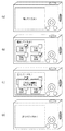
S305において、画像処理部109は、S304の処理の完了の後、すなわち、インデックス情報を取得した後に、近接無線通信により通信接続されたデジタルカメラ100aとの切断を促す報知処理を行う。具体的には、報知処理では、画像表示部112へ切断を促すメッセージが表示される。なお、報知処理では、スピーカ136からの切断を促す音声出力などが行われてもよい。例えば、図8(a)に示すように、装置を離すことで通信接続の解除を促すメッセージが画像表示部112に表示される。この報知処理により、デジタルカメラ100bを操作するユーザに対して近接無線通信による通信接続の解除を促すことができる。なお、通信接続の解除については、図2で示すように、装置同士の距離を通信不可能になるまで遠ざければよい。
In step S305, the
次いで、S306において、画像処理部109は、近接無線通信による外部機器との通信接続が切断されたか否かを検出する処理を行う。この切断検出については、前述したS301における通信接続の検出時の場合と同様であり、例えば、コネクタ(アンテナ)130の受信に応じて通信部129から画像処理部109へ出力される検出信号などに基づいて行われる。通信の切断が検出された場合、画像処理部109はS307のステップに処理が移行する。また、S306の処理は、外部機器との通信切断が検出されるまでループして行われる。
In step S <b> 306, the
S307において、画像処理部109は、転送する画像ファイルを指定するため、インデックス情報に基づいた転送候補の画像ファイルを一覧表示して操作部を介してユーザから選択可能とする指定画面を画像表示部112に表示する処理を行う。このステップでは、デジタルカメラ100bの画像処理部109がS304にて保存したインデックス情報を解析してサムネイルの画像ファイルを再生してサムネイル表示を行い、転送すべき画像を指定するための選択画面を生成する。この選択画面の表示プログラムや選択画面を用いて選択指示を受け付けるユーザインターフェイスのプログラムは、予め不揮発性メモリ116に保存されている。本ステップの処理が開始されると、自動的に不揮発性メモリ116に保存された上記プログラムが順次ロードされ、画像表示部112に選択画面のユーザインターフェイスが表示される。
In step S <b> 307, the
サムネイルは、前述の選択画面における所定の場所(例えば日付順やデータサイズ順などの並び順に応じた場所)に表示される。例えば、図8(b)に示すように、画像表示部112には、S304で保存されたインデックス情報のテキストファイルに記載された4つのサムネイル画像が、画像の選択画面に係るプログラムの実行によりサムネイル表示される。このような選択画面は、デジタルカメラ100aとデジタルカメラ100bとが通信接続している間は表示せず、通信接続が切断されてはじめて表示させるようにした。このようにしたのは以下の理由による。すなわち、通信接続している状態で選択画面が表示されてしまうと、ユーザは機器を近接させたまま選択操作を行おうとしてしまうおそれがある。そこでデジタルカメラ100aは、通信接続している間は切断を促す画面を表示し、通信接続が切断されてはじめて選択画面を表示させることとした。
The thumbnail is displayed in a predetermined place (for example, a place corresponding to the order of arrangement such as date order or data size order) on the selection screen described above. For example, as shown in FIG. 8B, the
S308において、画像処理部109は、転送すべき画像を指定する処理を行う。具体的には、S308では、S307において画像表示部112に表示された選択画面を見たユーザからの操作指示を操作部120で受け付けて、ユーザによる転送すべき画像の指定を受け付ける。図8(b)に示すように、選択画面における各画像には、チェックボックスコントロール(以下、チェックボックス)が配置されている。転送すべき画像の指定は、そのチェックボックスに操作部120を操作してチェックマークを入れて行われる。例えば、図示例では、「THM_0001」と「THM_0004」が転送すべき画像として指定されている。
In step S308, the
なお、本実施形態では、インデックス情報に画像のファイルサイズが記載されており、画像処理部109はインデックス情報に基づき、チェックボックスにチェックマークが入った画像のファイルサイズを加算している。この加算値がデジタルカメラ100bの記憶部131の空き容量よりも大きくなると、デジタルカメラ100aからの画像の取得が困難となる。この場合、画像処理部109は、図8(c)に示すような、転送すべき画像の指定ができない旨の警告メッセージを画像表示部112に表示して、指定する画像を制限する。
In this embodiment, the file size of the image is described in the index information, and the
S309において、画像処理部109は、インデックス情報を編集する処理を行い、S301に処理が戻る。具体的には、デジタルカメラ100bを操作するユーザが転送すべき画像の指定を完了した後、指定完了を通知する操作、例えば操作部120のセットボタンの押下が実行されると、インデックス情報のテキストファイルが更新される。そして、S309では、図8(d)に示すように、デジタルカメラ100aとデジタルカメラ100bとの近接無線通信による通信接続を再開させるため、互いの接近を促すメッセージが画像表示部112に表示される。
In step S309, the
S309におけるインデックス情報のテキストファイルの更新では、図9に示すように、転送の有無を示す情報が付加される。例えば、XYZ_0001.jpgとXYZ_0004.jpgが転送すべき画像ファイルとして指定された場合、転送するか否かを示す項目(TRANS)に「YES」が付加される。また、転送すべき画像ファイルとして指定されない場合には、「NO」が付加される。 In the update of the index information text file in S309, information indicating the presence or absence of transfer is added as shown in FIG. For example, XYZ_0001. jpg and XYZ_0004. When jpg is designated as an image file to be transferred, “YES” is added to an item (TRANS) indicating whether or not to transfer. If the image file to be transferred is not designated, “NO” is added.
次に、S301に処理が戻り、デジタルカメラ100aとデジタルカメラ100bとの近接無線通信による通信接続が再開された場合の処理、すなわち、S310以降の処理について説明する。
Next, the processing when the processing returns to S301 and the communication connection by the close proximity wireless communication between the
S310において、画像処理部109は、更新したインデックス情報を、再び接続されたデジタルカメラ100aへ送信する処理を行う。このステップでは、インデックス情報のテキストファイルをデジタルカメラ100aへ送信する。前述したように、デジタルカメラ100aへ送信するテキストファイルには、転送すべき画像ファイルに「YES」が付加されている。従って、デジタルカメラ100aは、後述する処理により、テキストファイルにより転送が指定された画像ファイルをデジタルカメラ100bへ送信することとなる。
In S310, the
S311において、画像処理部109は、インデックス情報のテキストファイルにより指定した画像データ(画像ファイル)であり、デジタルカメラ100aから送信される画像データを受信して取得する処理を行う。前述した図9の例では、XYZ_0001.jpgとXYZ_0004.jpgがデジタルカメラ100aからデジタルカメラ100bに転送されることとなる。
In step S311, the
また、S311では、図10に示すように、転送中であることを示すメッセージがデジタルカメラ100bの画像表示部112に表示される。なお、途中で通信が途切れた場合は、次回通信時に画像処理部109がS310からの処理をやり直すことで画像データを取得することも可能である。
In S311, as shown in FIG. 10, a message indicating that transfer is in progress is displayed on the
S312において、画像処理部109は、S311における画像データの取得が完了したことを検出すると、図10に例示したメッセージの表示を中止し、図8(a)に例示した通信接続の解除を促すメッセージを画像表示部112に表示させる報知処理を行う。すなわち、デジタルカメラ100bでは、この報知処理により、指定されたデータを取得した後に、デジタルカメラ100bを操作するユーザに対して近接無線通信による通信接続の解除を促すことができる。なお、S311における画像データの取得が完了したことを検出した場合、画像処理部109は受信したインデックス情報を自動的に削除してもよい。このことにより、デジタルカメラ100bの記憶部131の容量を削減することが可能となる。
In S312, when the
上述した処理により、デジタルカメラ100bでは、デジタルカメラ100aからデータを取得する際に、近接無線通信による通信接続を保つことなく、転送すべきデータをデジタルカメラ100bで選択することが可能となる。また、選択された転送すべきデータは、近接無線通信によりデジタルカメラ100aと再び通信接続された際に、取得されることとなる。具体的には、図11に示すように、デジタルカメラ100aから取得したインデックス情報に基づいて指定したXYZ_0001.jpg、XYZ_0004.jpgが再接続された際に取得されることとなる。
Through the processing described above, the
[データを供給するデジタルカメラ100aの処理内容]
次に、デジタルカメラ100aの画像処理部109の制御のもとで行われる処理について、図12を参照して説明する。図12に示すように、S401において、画像処理部109は、外部機器であるデジタルカメラ100bとの近接無線通信による通信接続を検出する処理を行う。このS401における処理は、S301と同様である。具体的には、コネクタ(アンテナ)130の受信に応じて通信部129から画像処理部109へ出力される検出信号などに基づいて行われ、外部機器との近接無線通信の確立が検出されるまでループされる。
[Processing content of
Next, processing performed under the control of the
S402において、画像処理部109は、前述したS302と同様、通信する相手のデバイスIDを取得する処理を行う。次いで、S403において、画像処理部109は、S303と同様、前回通信した外部機器であるか否か、すなわち、S401で通信接続されるより以前に通信接続した外部機器であるか否かを判定する。
In step S <b> 402, the
S403以降のステップについては、先ず、デジタルカメラ100a、100bが初めて通信を行ったものとして、S404以降のステップを説明する。S404において、画像処理部109は、インデックス情報を近接無線通信により外部機器であるデジタルカメラ100bへ送信する。このステップでは、画像処理部109は、記憶部131に記憶されたデータの一覧を取得し、前述したインデックス情報を生成した後に、デジタルカメラ100bへ送信する。具体的には、インデックス情報として、記憶部131に記憶されたデータである画像ファイルのファイルパス、ファイルサイズなどを書き出したテキストファイルと、その画像ファイルから生成したサムネイルデータをデジタルカメラ100bへ送信する。
Regarding the steps after S403, first, the steps after S404 will be described on the assumption that the
S405において、画像処理部109は、S404の処理の完了の後、すなわち、インデックス情報を送信した後に、近接無線通信により通信接続されたデジタルカメラ100bとの切断を促す報知処理をS304と同様に行う。この報知処理により、デジタルカメラ100aを操作するユーザに対して近接無線通信による通信接続の解除を促すことができる。
In step S405, the
次いで、S406において、画像処理部109は、近接無線通信による外部機器との通信接続が切断されたか否かを検出する処理をS306と同様に行い、S301に処理を戻す。従って、デジタルカメラ100aでは、S406の後、近接無線通信による通信接続が行われるまで待機されることとなる。この間、デジタルカメラ100bでは、図8(b)に示す画面が表示され、デジタルカメラ100bのユーザにより送信対象となる画像が選択される。
Next, in S406, the
次に、S401に処理が戻り、デジタルカメラ100aとデジタルカメラ100bとの近接無線通信による通信接続が再開された場合の処理、すなわち、S407以降の処理について説明する。
Next, the processing when the processing returns to S401 and the communication connection by the close proximity wireless communication between the
S407において、画像処理部109は、再び接続されたデジタルカメラ100aから、以前の通信接続で送信した後に更新されたインデックス情報を受信する処理を行う。このステップでは、前述したS310によりデジタルカメラ100bから送信されたインデックス情報のテキストファイルを受信する。受信したインデックス情報のテキストファイルは、記憶部131などに保存される。具体的には、図13に示すように、受信したインデックス情報のテキストファイルは、デジタルカメラ100aの「MISC」フォルダ内にテキストファイル(RE_TRANSFER.txt)として保存されるものとする。
In step S <b> 407, the
S408において、画像処理部109は、S407で受信したインデックス情報を解析する処理を行う。S407において記憶部131に保存したインデックス情報のテキストファイルには、前述したS309の処理により転送すべき画像ファイルが指定(「TRANS」項目に「YES」が付加)されている。従って、画像処理部109は、インデックス情報のテキストファイルを解析して、転送すべき画像ファイルとして指定されている画像のファイルパスからデジタルカメラ100bへ送信する画像ファイルを記憶部131からロードする。例えば、図13に例示したデジタルカメラ100aに保存されているXYZ_0001.jpgとXYZ_0004.jpgが転送すべき画像ファイルとして記憶部131からロードされる。
In step S408, the
S409において、画像処理部109は、S408により記憶部131からロードされた画像ファイルをデジタルカメラ100bへ送信する処理を行う。S409では、例えば、前述したXYZ_0001.jpgとXYZ_0004.jpgがデジタルカメラ100bへ送信されることとなる。
In step S409, the
また、S409では、S311と同様、図10に示すような転送中であることを示すメッセージがデジタルカメラ100aの画像表示部112に表示される。なお、途中で通信が途切れた場合は、次回通信時に画像処理部109がS409の処理をやり直すことで画像ファイルを再送信することも可能である。また、画像処理部109は、通信が途切れた時点で未送信の画像を判定し、次回の通信時には未送信の画像から送信を行ってもよい。
In S409, as in S311, a message indicating that transfer is in progress as shown in FIG. 10 is displayed on the
S410において、画像処理部109は、S409における画像ファイルの送信が完了したことを検出すると、図10に例示したメッセージの表示を中止しする。次いで、画像処理部109は、図8(a)に例示した通信接続の解除を促すメッセージを画像表示部112に表示させる報知処理を行う。すなわち、デジタルカメラ100aでは、この報知処理により、指定されたデータを取得した後に、デジタルカメラ100aを操作するユーザに対して近接無線通信による通信接続の解除を促すことができる。また、S410では、不必要となったインデックス情報のテキストファイル(図13に例示したRE_TRANSFER.txt)が削除されてもよい。
In S410, when detecting that the transmission of the image file in S409 is completed, the
上述した処理により、デジタルカメラ100aでは、デジタルカメラ100bにデータを供給する際に、近接無線通信による通信接続を保つことなく、デジタルカメラ100b側における転送すべきデータの選択指定を行わせることが可能となる。また、デジタルカメラ100bで選択された転送すべきデータは、近接無線通信により再び通信接続された際に、デジタルカメラ100aから供給されることとなる。具体的には、前述した図11に例示したように、デジタルカメラ100bから指定されたXYZ_0001.jpg、XYZ_0004.jpgが再接続された際に供給されることとなる。
Through the above-described processing, when supplying data to the
なお、上述した実施の形態における記述は、一例を示すものであり、これに限定するものではない。上述した実施の形態における構成及び動作に関しては、適宜変更が可能である。 Note that the description in the above-described embodiment shows an example, and the present invention is not limited to this. The configuration and operation in the embodiment described above can be changed as appropriate.
例えば、本実施形態ではデジタルカメラ同士でデータを送受信する構成を例示したが、一方がパーソナルコンピュータや通信機能を備えたテレビシステムなどの情報処理装置であってもよい。 For example, in the present embodiment, a configuration in which data is transmitted and received between digital cameras is illustrated, but one of the information processing apparatuses such as a personal computer or a television system having a communication function may be used.
(他の実施形態)
上述の実施形態は、システム或は装置のコンピュータ(或いはCPU、MPU等)によりソフトウェア的に実現することも可能である。従って、上述の実施形態をコンピュータで実現するために、該コンピュータに供給されるコンピュータプログラム自体も本発明を実現するものである。つまり、上述の実施形態の機能を実現するためのコンピュータプログラム自体も本発明の一つである。
(Other embodiments)
The above-described embodiment can also be realized in software by a computer of a system or apparatus (or CPU, MPU, etc.). Therefore, the computer program itself supplied to the computer in order to implement the above-described embodiment by the computer also realizes the present invention. That is, the computer program itself for realizing the functions of the above-described embodiments is also one aspect of the present invention.
なお、上述の実施形態を実現するためのコンピュータプログラムは、コンピュータで読み取り可能であれば、どのような形態であってもよい。例えば、オブジェクトコード、インタプリタにより実行されるプログラム、OSに供給するスクリプトデータ等で構成することができるが、これらに限るものではない。上述の実施形態を実現するためのコンピュータプログラムは、記憶媒体又は有線/無線通信によりコンピュータに供給される。プログラムを供給するための記憶媒体としては、例えば、フレキシブルディスク、ハードディスク、磁気テープ等の磁気記憶媒体、MO、CD、DVD等の光/光磁気記憶媒体、不揮発性の半導体メモリなどがある。 The computer program for realizing the above-described embodiment may be in any form as long as it can be read by a computer. For example, it can be composed of object code, a program executed by an interpreter, script data supplied to the OS, but is not limited thereto. A computer program for realizing the above-described embodiment is supplied to a computer via a storage medium or wired / wireless communication. Examples of the storage medium for supplying the program include a magnetic storage medium such as a flexible disk, a hard disk, and a magnetic tape, an optical / magneto-optical storage medium such as an MO, CD, and DVD, and a nonvolatile semiconductor memory.
有線/無線通信を用いたコンピュータプログラムの供給方法としては、コンピュータネットワーク上のサーバを利用する方法がある。この場合、本発明を形成するコンピュータプログラムとなりうるデータファイル(プログラムファイル)をサーバに記憶しておく。プログラムファイルとしては、実行形式のものであっても、ソースコードであっても良い。そして、このサーバにアクセスしたクライアントコンピュータに、プログラムファイルをダウンロードすることによって供給する。この場合、プログラムファイルを複数のセグメントファイルに分割し、セグメントファイルを異なるサーバに分散して配置することも可能である。つまり、上述の実施形態を実現するためのプログラムファイルをクライアントコンピュータに提供するサーバ装置も本発明の一つである。 As a computer program supply method using wired / wireless communication, there is a method of using a server on a computer network. In this case, a data file (program file) that can be a computer program forming the present invention is stored in the server. The program file may be an executable format or a source code. Then, the program file is supplied by downloading to a client computer that has accessed the server. In this case, the program file can be divided into a plurality of segment files, and the segment files can be distributed and arranged on different servers. That is, a server apparatus that provides a client computer with a program file for realizing the above-described embodiment is also one aspect of the present invention.
また、上述の実施形態を実現するためのコンピュータプログラムを暗号化して格納した記憶媒体を配布し、所定の条件を満たしたユーザに、暗号化を解く鍵情報を供給し、ユーザの有するコンピュータへのインストールを許可してもよい。鍵情報は、例えばインターネットを介してホームページからダウンロードさせることによって供給することができる。また、上述の実施形態を実現するためのコンピュータプログラムは、すでにコンピュータ上で稼働するOSの機能を利用するものであってもよい。さらに、上述の実施形態を実現するためのコンピュータプログラムは、その一部をコンピュータに装着される拡張ボード等のファームウェアで構成してもよいし、拡張ボード等が備えるCPUで実行するようにしてもよい。 In addition, a storage medium in which the computer program for realizing the above-described embodiment is encrypted and distributed is distributed, and key information for decrypting is supplied to a user who satisfies a predetermined condition, and the user's computer Installation may be allowed. The key information can be supplied by being downloaded from a homepage via the Internet, for example. Further, the computer program for realizing the above-described embodiment may use an OS function already running on the computer. Further, a part of the computer program for realizing the above-described embodiment may be configured by firmware such as an expansion board attached to the computer, or may be executed by a CPU provided in the expansion board. Good.
100、100a、100b デジタルカメラ
101 撮影レンズ
102 シャッター
103 撮像素子
104 A/D変換器
105 タイミング発生部
106 メモリ制御部
107 中央制御部
108 D/A変換器
109 画像処理部
110 メモリ
111 圧縮/伸長部
112 画像表示部
113 光学ファインダ
114 フラッシュ
115 システムメモリ
116 不揮発性メモリ
117 モード切替スイッチ
118 第1シャッタースイッチ
119 第2シャッタースイッチ
120 操作部
121 電源制御部
122 コネクタ
123 コネクタ
124 電源部
125 I/F
126 コネクタ
127 記憶媒体着脱検知部
128 バリア
129 通信部
130 コネクタ(アンテナ)
131 記憶部
132 I/F
133 コネクタ
134 RTC
135 音声制御部
136 スピーカ
137 マイク
138 動画ボタン
199 記憶媒体
201 送受信部
100, 100a,
126
131 Storage unit 132 I / F
133
135 Audio Control
Claims (12)
近接無線通信によりデータ送信装置と通信するための通信手段と、A communication means for communicating with the data transmission device by proximity wireless communication;
前記データ送信装置との接続の状態を検知する検知手段と、Detecting means for detecting a state of connection with the data transmitting device;
前記通信手段を介して前記データ送信装置と第1の接続を確立したことが前記検知手段により検知された場合、前記通信手段は、前記データ送信装置の記憶媒体に記憶されたデータの一覧を示すインデックス情報を前記データ送信装置から受信し、When the detection means detects that the first connection with the data transmission apparatus is established via the communication means, the communication means shows a list of data stored in the storage medium of the data transmission apparatus Receiving index information from the data transmission device;
前記インデックス情報の受信後、前記インデックス情報に基づいて前記データ送信装置から受信するデータの指定を受け付ける指定手段をさらに有し、After receiving the index information, further comprising a designation means for accepting designation of data received from the data transmission device based on the index information;
前記指定手段によりデータの指定が受け付けられた後であり、かつ前記検知手段により前記第1の接続の切断が検知された後で、前記通信手段を介して前記データ送信装置と第2の接続を確立した場合、前記通信手段を介して前記指定手段により指定されたデータを前記データ送信装置から受信することを特徴とするデータ受信装置。After the designation of data is accepted by the designation means and after the disconnection of the first connection is detected by the detection means, the data transmission device and the second connection are connected via the communication means. When established, the data receiving apparatus receives data specified by the specifying means from the data transmitting apparatus via the communication means.
前記第1の接続の切断が検知された後で、前記検知手段が外部装置との接続の確立を検知した場合、前記メモリに予め記憶された識別情報と、前記外部装置から受信した識別情報とを比較して、前記第1の接続を確立していたデータ送信装置と前記第2の接続を確立したか否かを判定する判定手段とをさらに有する請求項1に記載のデータ受信装置。After the detection of the disconnection of the first connection, when the detection means detects the establishment of the connection with the external device, the identification information stored in advance in the memory and the identification information received from the external device; The data receiving apparatus according to claim 1, further comprising: a data transmitting apparatus that has established the first connection and a determination unit that determines whether or not the second connection has been established.
前記指定手段は、前記一覧から受信するデータの指定を受け付けることを特徴とする請求項1乃至3のいずれか1項に記載のデータ受信装置。The data receiving apparatus according to claim 1, wherein the designation unit accepts designation of data received from the list.
近接無線通信によりデータ受信装置と通信するための通信手段と、A communication means for communicating with the data receiving device by proximity wireless communication;
前記データ受信装置との接続の状態を検知する検知手段とを有し、Detecting means for detecting a state of connection with the data receiving device;
前記通信手段を介して前記データ受信装置と第1の接続を確立したことが前記検知手段により検知された場合、前記通信手段を介して、前記データ送信装置の記憶媒体に記憶されたデータの一覧を示すインデックス情報を前記データ受信装置に送信し、A list of data stored in the storage medium of the data transmission device via the communication means when the detection means detects that the first connection with the data reception device has been established via the communication means Is sent to the data receiver,
前記インデックス情報を送信した後であり、かつ前記検知手段により前記第1の接続の切断が検知された後で、前記通信手段を介して前記データ受信装置と第2の接続を確立した場合、前記インデックス情報に基づき前記データ受信装置により選択されたデータを、前記通信手段を介して前記データ受信装置に送信するデータ送信装置。After establishing the second connection with the data receiving device via the communication means after transmitting the index information and after detecting the disconnection of the first connection by the detecting means, A data transmission device that transmits data selected by the data reception device based on index information to the data reception device via the communication means.
前記第1の接続の切断が検知された後で、前記検知手段が外部装置との接続の確立を検知した場合、前記メモリに予め記憶された識別情報と、前記データ受信装置から受信した識別情報とを比較して、前記第1の接続を確立していたデータ受信装置と前記第2の接続を確立したか否かを判定する判定手段とを有する請求項6に記載のデータ送信装置。After the detection of the disconnection of the first connection, when the detection unit detects the establishment of a connection with an external device, the identification information stored in advance in the memory and the identification information received from the data receiving device The data transmission device according to claim 6, further comprising: a data reception device that has established the first connection and a determination unit that determines whether or not the second connection has been established.
前記データ送信装置との接続の状態を検知する検知工程と、A detection step of detecting a state of connection with the data transmission device;
前記通信手段を介して前記データ送信装置と第1の接続を確立したことが前記検知工程で検知された場合、前記通信手段を介して、前記データ送信装置の記憶媒体に記憶されたデータの一覧を示すインデックス情報を前記データ送信装置から受信するインデックス受信工程と、A list of data stored in the storage medium of the data transmission device via the communication means when the detection step detects that the first connection with the data transmission device has been established via the communication means Index receiving step for receiving index information indicating the data from the data transmitting device;
前記インデックス受信工程での前記インデックス情報の受信後、前記インデックス情報に基づいて前記データ送信装置から受信するデータの指定を受け付ける指定工程と、A designation step for accepting designation of data received from the data transmission device based on the index information after receiving the index information in the index reception step;
前記指定工程でデータの指定が受け付けられた後であり、かつ前記検知工程で前記第1の接続の切断が検知された後で、前記通信手段を介して前記データ送信装置と第2の接続を確立した場合、前記通信手段を介して前記指定工程で指定されたデータを前記データ送信装置から受信するデータ受信工程とAfter the designation of data is accepted in the designation step and after the disconnection of the first connection is detected in the detection step, the data transmission device and the second connection are connected via the communication means. If established, a data receiving step for receiving data designated in the designation step from the data transmitting device via the communication means;
を有することを特徴とするデータ受信装置の制御方法。A method for controlling a data receiving apparatus.
前記データ受信装置との接続の状態を検知する検知工程と、A detection step of detecting a connection state with the data receiving device;
前記通信手段を介して前記データ受信装置と第1の接続を確立したことが前記検知工程で検知された場合、前記通信手段を介して、前記データ送信装置の記憶媒体に記憶されたデータの一覧を示すインデックス情報を前記データ受信装置に送信するインデックス送信工程と、A list of data stored in the storage medium of the data transmission device via the communication means when the detection step detects that the first connection with the data reception device has been established via the communication means. An index transmission step of transmitting index information indicating to the data receiving device;
前記インデックス送信工程で前記インデックス情報を送信した後であり、かつ前記検知工程で前記第1の接続の切断が検知された後で、前記通信手段を介して前記データ受信装置と第2の接続を確立した場合、前記インデックス情報に基づき前記データ受信装置により選択されたデータを、前記通信手段を介して前記データ受信装置に送信するデータ送信工程After the transmission of the index information in the index transmission step and after the disconnection of the first connection is detected in the detection step, a second connection is established with the data receiving device via the communication means. A data transmission step of transmitting data selected by the data receiving device based on the index information to the data receiving device via the communication means when established
とを有することを特徴とするデータ送信装置の制御方法。A method for controlling a data transmitting apparatus.
前記コンピュータを、
前記データ送信装置との接続の状態を検知する検知手段、
前記通信手段を介して前記データ送信装置と第1の接続を確立したことが前記検知工程で検知された場合、前記通信手段を介して、前記データ送信装置の記憶媒体に記憶されたデータの一覧を示すインデックス情報を前記データ送信装置から受信するインデックス受信手段、
前記インデックス受信手段での前記インデックス情報の受信後、前記インデックス情報に基づいて前記データ送信装置から受信するデータの指定を受け付ける指定手段、
前記指定手段でデータの指定が受け付けられた後であり、かつ前記検知手段で前記第1の接続の切断が検知された後で、前記通信手段を介して前記データ送信装置と第2の接続を確立した場合、前記通信手段を介して前記指定手段で指定されたデータを前記データ送信装置から受信するデータ受信手段
として機能させることを特徴とするプログラム。 A program that causes a computer to function as a data receiving device by being read and executed by a computer having communication means for communicating with the data transmitting device by proximity wireless communication,
The computer,
Detecting means for detecting a connection state with the data transmitting device;
A list of data stored in the storage medium of the data transmission device via the communication means when the detection step detects that the first connection with the data transmission device has been established via the communication means Index receiving means for receiving index information indicating from the data transmitting device,
A designation unit that receives designation of data received from the data transmission device based on the index information after receiving the index information in the index reception unit;
After the designation of the data is accepted by the designation means and after the disconnection of the first connection is detected by the detection means, the data transmission device and the second connection are connected via the communication means. Data receiving means for receiving data designated by the designation means from the data transmitting device via the communication means when established
A program characterized by functioning as
前記コンピュータを、
前記データ受信装置との接続の状態を検知する検知手段、
前記通信手段を介して前記データ受信装置と第1の接続を確立したことが前記検知手段で検知された場合、前記通信手段を介して、前記データ送信装置の記憶媒体に記憶されたデータの一覧を示すインデックス情報を前記データ受信装置に送信するインデックス送信手段、
前記インデックス送信手段で前記インデックス情報を送信した後であり、かつ前記検知手段で前記第1の接続の切断が検知された後で、前記通信手段を介して前記データ受信装置と第2の接続を確立した場合、前記インデックス情報に基づき前記データ受信装置により選択されたデータを、前記通信手段を介して前記データ受信装置に送信するデータ送信手段
として機能させることを特徴とするプログラム。 A program that causes a computer to function as a data transmission device by being read and executed by a computer having communication means for communicating with the data reception device by proximity wireless communication,
The computer,
Detecting means for detecting a state of connection with the data receiving device;
A list of data stored in the storage medium of the data transmission device via the communication means when the detection means detects that the first connection with the data reception device has been established via the communication means Index transmission means for transmitting index information indicating to the data receiving device,
After the transmission of the index information by the index transmission means and after the disconnection of the first connection is detected by the detection means, a second connection is established with the data receiving device via the communication means. Data transmission means for transmitting data selected by the data receiving apparatus based on the index information to the data receiving apparatus via the communication means when established
A program characterized by functioning as
Priority Applications (8)
| Application Number | Priority Date | Filing Date | Title |
|---|---|---|---|
| JP2008171237A JP5084640B2 (en) | 2008-06-30 | 2008-06-30 | Data receiving apparatus, data transmitting apparatus, control method and program thereof |
| US12/936,219 US8731469B2 (en) | 2008-06-30 | 2009-06-09 | Data receiving apparatus, data transmitting apparatus, method for controlling the same and program |
| BRPI0912650A BRPI0912650A2 (en) | 2008-06-30 | 2009-06-09 | data receiving and data transmission apparatus, method for controlling a data receiving apparatus, and computer readable storage media |
| EP09773290.3A EP2294813B1 (en) | 2008-06-30 | 2009-06-09 | Data receiving apparatus, data transmitting apparatus, method for controlling the same and program |
| RU2011103169/07A RU2451420C1 (en) | 2008-06-30 | 2009-06-09 | Data receiving apparatus, data transmitting apparatus, method of controlling said apparatus and program |
| KR1020117001836A KR101230409B1 (en) | 2008-06-30 | 2009-06-09 | Data receiving apparatus, data transmitting apparatus, method for controlling the same and storage medium |
| PCT/JP2009/060819 WO2010001712A1 (en) | 2008-06-30 | 2009-06-09 | Data receiving apparatus, data transmitting apparatus, method for controlling the same and program |
| CN2009801253086A CN102077581B (en) | 2008-06-30 | 2009-06-09 | Data receiving apparatus, data transmitting apparatus, method for controlling the same |
Applications Claiming Priority (1)
| Application Number | Priority Date | Filing Date | Title |
|---|---|---|---|
| JP2008171237A JP5084640B2 (en) | 2008-06-30 | 2008-06-30 | Data receiving apparatus, data transmitting apparatus, control method and program thereof |
Publications (3)
| Publication Number | Publication Date |
|---|---|
| JP2010011363A JP2010011363A (en) | 2010-01-14 |
| JP2010011363A5 JP2010011363A5 (en) | 2011-08-11 |
| JP5084640B2 true JP5084640B2 (en) | 2012-11-28 |
Family
ID=41465815
Family Applications (1)
| Application Number | Title | Priority Date | Filing Date |
|---|---|---|---|
| JP2008171237A Expired - Fee Related JP5084640B2 (en) | 2008-06-30 | 2008-06-30 | Data receiving apparatus, data transmitting apparatus, control method and program thereof |
Country Status (8)
| Country | Link |
|---|---|
| US (1) | US8731469B2 (en) |
| EP (1) | EP2294813B1 (en) |
| JP (1) | JP5084640B2 (en) |
| KR (1) | KR101230409B1 (en) |
| CN (1) | CN102077581B (en) |
| BR (1) | BRPI0912650A2 (en) |
| RU (1) | RU2451420C1 (en) |
| WO (1) | WO2010001712A1 (en) |
Cited By (3)
| Publication number | Priority date | Publication date | Assignee | Title |
|---|---|---|---|---|
| US9742976B2 (en) | 2014-07-08 | 2017-08-22 | International Business Machines Corporation | Peer to peer camera communication |
| US9781320B2 (en) | 2014-07-08 | 2017-10-03 | International Business Machines Corporation | Peer to peer lighting communication |
| US9948846B2 (en) | 2014-07-08 | 2018-04-17 | International Business Machines Corporation | Peer to peer audio video device communication |
Families Citing this family (19)
| Publication number | Priority date | Publication date | Assignee | Title |
|---|---|---|---|---|
| JP5129669B2 (en) * | 2008-06-30 | 2013-01-30 | キヤノン株式会社 | Image forming apparatus and control method thereof, image supply apparatus and control method thereof |
| JP5832260B2 (en) | 2011-12-02 | 2015-12-16 | キヤノン株式会社 | Recording medium and imaging apparatus using the same |
| WO2013097346A1 (en) * | 2011-12-27 | 2013-07-04 | 中兴通讯股份有限公司 | Method, terminal, and system for self-service acquisition of media resource |
| CN103188330A (en) * | 2011-12-31 | 2013-07-03 | 北大方正集团有限公司 | Method and system of file transfer |
| JP6012203B2 (en) | 2012-03-05 | 2016-10-25 | キヤノン株式会社 | Image processing apparatus and control method |
| ES2864883T3 (en) * | 2013-03-12 | 2021-10-14 | Hoffmann La Roche | Procedure for transmitting a glucose measurement, procedure for displaying the status during a wireless transmission of a glucose measurement, and pocket glucometer |
| US8895316B2 (en) | 2013-03-12 | 2014-11-25 | Roche Diagnostics Operations, Inc. | Transferring blood glucose measures seamlessly from a handheld glucose meter |
| JP5527492B1 (en) | 2013-08-19 | 2014-06-18 | ソニー株式会社 | Imaging apparatus, control method, and program |
| JP6207298B2 (en) * | 2013-08-19 | 2017-10-04 | キヤノン株式会社 | COMMUNICATION DEVICE, ITS CONTROL METHOD, AND PROGRAM |
| JP5541430B1 (en) | 2013-08-19 | 2014-07-09 | ソニー株式会社 | Imaging unit, mounting device |
| JP6335466B2 (en) * | 2013-10-04 | 2018-05-30 | キヤノン株式会社 | COMMUNICATION DEVICE, COMMUNICATION DEVICE CONTROL METHOD, AND PROGRAM |
| WO2016024432A1 (en) * | 2014-08-12 | 2016-02-18 | ソニー株式会社 | Information-processing device, information processing method, and program |
| JP6498104B2 (en) | 2015-11-16 | 2019-04-10 | キヤノン株式会社 | COMMUNICATION DEVICE AND ITS CONTROL METHOD |
| JP6748582B2 (en) * | 2017-01-10 | 2020-09-02 | キヤノン株式会社 | Imaging device, control method thereof, program, and recording medium |
| CN108462817B (en) * | 2017-02-22 | 2021-01-05 | 佳能株式会社 | Communication apparatus, control method thereof, and storage medium |
| CN109587322B (en) * | 2017-09-29 | 2021-07-16 | 华为终端有限公司 | Message processing method, message viewing method and terminal |
| JP7101525B2 (en) | 2018-04-20 | 2022-07-15 | キヤノン株式会社 | Electronic devices and their control methods, as well as programs |
| KR20200111989A (en) * | 2019-03-20 | 2020-10-05 | 삼성전자주식회사 | Electronic device for searching a file information stored in external device and method of operating thereof |
| JP2021043423A (en) * | 2019-09-13 | 2021-03-18 | キヤノン株式会社 | Image forming apparatus |
Family Cites Families (15)
| Publication number | Priority date | Publication date | Assignee | Title |
|---|---|---|---|---|
| RU2169437C1 (en) * | 1998-12-29 | 2001-06-20 | Свисском Мобиле Аг | Procedure to gain access to objects for users of telecommunication network |
| JP2001016568A (en) * | 1999-06-30 | 2001-01-19 | Fuji Photo Film Co Ltd | Image communication system |
| JP2001216391A (en) * | 2000-02-02 | 2001-08-10 | Seiko Epson Corp | Method and system for managing reception of order |
| US7304665B2 (en) | 2001-03-21 | 2007-12-04 | Canon Kabushiki Kaisha | Image transfer system and display method in which a stored image is transferred to an image display device |
| JP4314506B2 (en) * | 2001-09-28 | 2009-08-19 | 富士フイルム株式会社 | Information receiving method, information receiving apparatus and program |
| RU2207724C1 (en) * | 2001-11-01 | 2003-06-27 | Общество с ограниченной ответственностью "Алгоритм" | Method of radio communication in wireless local network |
| JP3658370B2 (en) * | 2001-12-27 | 2005-06-08 | キヤノン株式会社 | Image storage device and data registration program for image storage device |
| JP3928489B2 (en) * | 2002-06-07 | 2007-06-13 | ソニー株式会社 | COMMUNICATION METHOD, COMMUNICATION SYSTEM, AND COMMUNICATION DEVICE |
| JP4085255B2 (en) | 2002-09-26 | 2008-05-14 | 富士フイルム株式会社 | Digital camera and image communication method |
| JP2006031531A (en) | 2004-07-20 | 2006-02-02 | Klab Inc | Information acquisition distribution system using advertisement panel |
| US8902320B2 (en) * | 2005-01-31 | 2014-12-02 | The Invention Science Fund I, Llc | Shared image device synchronization or designation |
| JP2007174247A (en) * | 2005-12-21 | 2007-07-05 | Sharp Corp | Transmitter, receiver, transmission program, receive program, and recoding medium |
| JP4635894B2 (en) * | 2006-02-13 | 2011-02-23 | ソニー株式会社 | Information processing apparatus and method, and program |
| US8209434B2 (en) * | 2006-06-22 | 2012-06-26 | Sony Ericsson Mobile Communications Ab | Continued transfer or streaming of a data file after loss of a local connection |
| US20080090520A1 (en) * | 2006-10-17 | 2008-04-17 | Camp William O | Apparatus and methods for communication mobility management using near-field communications |
-
2008
- 2008-06-30 JP JP2008171237A patent/JP5084640B2/en not_active Expired - Fee Related
-
2009
- 2009-06-09 BR BRPI0912650A patent/BRPI0912650A2/en not_active Application Discontinuation
- 2009-06-09 EP EP09773290.3A patent/EP2294813B1/en not_active Not-in-force
- 2009-06-09 KR KR1020117001836A patent/KR101230409B1/en active IP Right Grant
- 2009-06-09 US US12/936,219 patent/US8731469B2/en not_active Expired - Fee Related
- 2009-06-09 RU RU2011103169/07A patent/RU2451420C1/en not_active IP Right Cessation
- 2009-06-09 WO PCT/JP2009/060819 patent/WO2010001712A1/en active Application Filing
- 2009-06-09 CN CN2009801253086A patent/CN102077581B/en not_active Expired - Fee Related
Cited By (6)
| Publication number | Priority date | Publication date | Assignee | Title |
|---|---|---|---|---|
| US9742976B2 (en) | 2014-07-08 | 2017-08-22 | International Business Machines Corporation | Peer to peer camera communication |
| US9781320B2 (en) | 2014-07-08 | 2017-10-03 | International Business Machines Corporation | Peer to peer lighting communication |
| US9948846B2 (en) | 2014-07-08 | 2018-04-17 | International Business Machines Corporation | Peer to peer audio video device communication |
| US9955062B2 (en) | 2014-07-08 | 2018-04-24 | International Business Machines Corporation | Peer to peer audio video device communication |
| US10257404B2 (en) | 2014-07-08 | 2019-04-09 | International Business Machines Corporation | Peer to peer audio video device communication |
| US10270955B2 (en) | 2014-07-08 | 2019-04-23 | International Business Machines Corporation | Peer to peer audio video device communication |
Also Published As
| Publication number | Publication date |
|---|---|
| US20110028096A1 (en) | 2011-02-03 |
| KR101230409B1 (en) | 2013-02-06 |
| CN102077581B (en) | 2013-06-05 |
| EP2294813A4 (en) | 2011-07-27 |
| RU2451420C1 (en) | 2012-05-20 |
| BRPI0912650A2 (en) | 2016-01-26 |
| JP2010011363A (en) | 2010-01-14 |
| US8731469B2 (en) | 2014-05-20 |
| CN102077581A (en) | 2011-05-25 |
| EP2294813A1 (en) | 2011-03-16 |
| WO2010001712A1 (en) | 2010-01-07 |
| KR20110022709A (en) | 2011-03-07 |
| EP2294813B1 (en) | 2015-03-25 |
Similar Documents
| Publication | Publication Date | Title |
|---|---|---|
| JP5084640B2 (en) | Data receiving apparatus, data transmitting apparatus, control method and program thereof | |
| US9154651B2 (en) | Configuring apparatus, image output apparatus, methods of controlling the same, and program | |
| JP5351593B2 (en) | File management apparatus and control method thereof | |
| JP2010011364A (en) | Image output system and method of controlling the same, image input device and method of controlling the same, and image output device and method of controlling the same | |
| JP2010009521A (en) | Image providing apparatus, image output apparatus, and image output system | |
| JP4724512B2 (en) | Imaging apparatus, control method, control program, and storage medium | |
| JP5755347B2 (en) | COMMUNICATION CONTROL DEVICE, ITS CONTROL METHOD, PROGRAM, AND RECORDING MEDIUM | |
| US7961225B2 (en) | Data processing apparatus, method of controlling data processing apparatus, and computer-readable storage medium for use in controlling image sensing processing and image processing | |
| JP5213602B2 (en) | Imaging apparatus, control method thereof, and program | |
| JP4574077B2 (en) | COMMUNICATION SYSTEM, RADIO COMMUNICATION DEVICE, AND IMAGING DEVICE | |
| JP4799207B2 (en) | COMMUNICATION DEVICE, ITS CONTROL METHOD, PROGRAM | |
| JP2011130036A (en) | Imaging device | |
| JP4883803B2 (en) | COMMUNICATION DEVICE, ITS CONTROL METHOD, AND PROGRAM | |
| JP5535183B2 (en) | COMMUNICATION DEVICE, ITS CONTROL METHOD, AND PROGRAM | |
| JP2011066806A (en) | Image processor | |
| JP5562059B2 (en) | COMMUNICATION DEVICE, ITS CONTROL METHOD, PROGRAM | |
| JP5484545B2 (en) | Imaging apparatus, control method thereof, and program | |
| JP2017085518A (en) | Communication apparatus, control method for communication apparatus, and program | |
| JP2002101327A (en) | Image pickup device and method, storage medium, communication unit and method, and storage medium | |
| JP2021093700A (en) | Imaging apparatus | |
| JP5972085B2 (en) | Data transfer control device, control method thereof, and program | |
| JP2006287734A (en) | Imaging apparatus, image output device and image output system | |
| JP2008054191A (en) | Electronic device | |
| JP2009260744A (en) | Imaging apparatus and method of controlling the same, and program | |
| JP2007259126A (en) | Printer, imaging device, communication system and their control method |
Legal Events
| Date | Code | Title | Description |
|---|---|---|---|
| A521 | Request for written amendment filed |
Free format text: JAPANESE INTERMEDIATE CODE: A523 Effective date: 20110628 |
|
| A621 | Written request for application examination |
Free format text: JAPANESE INTERMEDIATE CODE: A621 Effective date: 20110628 |
|
| TRDD | Decision of grant or rejection written | ||
| A01 | Written decision to grant a patent or to grant a registration (utility model) |
Free format text: JAPANESE INTERMEDIATE CODE: A01 Effective date: 20120806 |
|
| A01 | Written decision to grant a patent or to grant a registration (utility model) |
Free format text: JAPANESE INTERMEDIATE CODE: A01 |
|
| A61 | First payment of annual fees (during grant procedure) |
Free format text: JAPANESE INTERMEDIATE CODE: A61 Effective date: 20120904 |
|
| R151 | Written notification of patent or utility model registration |
Ref document number: 5084640 Country of ref document: JP Free format text: JAPANESE INTERMEDIATE CODE: R151 |
|
| FPAY | Renewal fee payment (event date is renewal date of database) |
Free format text: PAYMENT UNTIL: 20150914 Year of fee payment: 3 |
|
| LAPS | Cancellation because of no payment of annual fees |