JP5083996B2 - Water leak measurement method - Google Patents
Water leak measurement method Download PDFInfo
- Publication number
- JP5083996B2 JP5083996B2 JP2009164255A JP2009164255A JP5083996B2 JP 5083996 B2 JP5083996 B2 JP 5083996B2 JP 2009164255 A JP2009164255 A JP 2009164255A JP 2009164255 A JP2009164255 A JP 2009164255A JP 5083996 B2 JP5083996 B2 JP 5083996B2
- Authority
- JP
- Japan
- Prior art keywords
- water
- water supply
- wall surface
- gap
- waterway
- Prior art date
- Legal status (The legal status is an assumption and is not a legal conclusion. Google has not performed a legal analysis and makes no representation as to the accuracy of the status listed.)
- Active
Links
Images


Landscapes
- Examining Or Testing Airtightness (AREA)
Description
本発明は、水路用コンクリートブロックからの漏水量や、水路用コンクリートブロックの継ぎ目に配される目地材からの漏水量を測定する水路の漏水測定方法に関するものである。 TECHNICAL FIELD The present invention relates to a water leak measurement method for a water channel that measures the amount of water leak from a concrete channel block for water channel and the amount of water leak from a joint material arranged at the joint of the concrete block for water channel.
例えば、農業用の用水路などは、断面U字状のコンクリート製水路用コンクリートブロックを多数並設状態に継合連結して構成されているが、従来、このような水路での水路用コンクリートブロック自体の漏水量や、水路用コンクリートブロックの継ぎ目に配された目地部からの漏水量を測定する方法は確立されていない。 For example, agricultural irrigation channels and the like are configured by joining and connecting a large number of concrete blocks for concrete water channels having a U-shaped cross section in a juxtaposed state. Conventionally, concrete blocks for water channels in such channels are themselves. There is no established method for measuring the amount of water leaked or the amount of water leaked from joints located at the joints of concrete blocks for waterways.
本発明は、現場にて簡単に水路用コンクリートブロックからの漏水量や、水路用コンクリートブロックの継ぎ目の目地材からの漏水量を測定可能となる画期的な水路の漏水測定方法を提供するものである。 The present invention provides an epoch-making waterway leakage measurement method capable of measuring the amount of water leakage from a concrete block for a waterway and the amount of water leakage from a joint material of a concrete block for a waterway at the site. It is.
添付図面を参照して本発明の要旨を説明する。 The gist of the present invention will be described with reference to the accompanying drawings.
水路用コンクリートブロック1を多数並設状態に継合連結して成る水路の漏水測定方法であって、前記水路用コンクリートブロック1の内壁面2に、この内壁面2を被覆して内壁面2との間に給水用間隙3を形成し得る給水口4を備えた被覆体5を配設すると共に、この被覆体5を前記内壁面2に固定して前記給水用間隙3を止水状態とし、半筒状の前記被覆体5を採用し、この被覆体5を前記水路用コンクリートブロック1の内壁面2に配設して接着固定若しくは圧着固定することにより、この被覆体5に覆われた前記給水用間隙3を形成し、この止水した給水用間隙3に前記給水口4から給水して所定時間放置後、この給水用間隙3での減水量を測定することを特徴とする水路の漏水測定方法に係るものである。
A method for measuring water leakage in a waterway comprising a plurality of waterway concrete blocks 1 connected in a juxtaposed manner, wherein the
また、水路用コンクリートブロック1を多数並設状態に継合連結して成る水路の漏水測定方法であって、前記水路用コンクリートブロック1の内壁面2に、この内壁面2を被覆して内壁面2との間に給水用間隙3を形成し得る給水口4を備えた被覆体5を配設すると共に、この被覆体5を前記内壁面2に固定して前記給水用間隙3を止水状態とし、柔軟性を有するシート状の前記被覆体5を採用し、この被覆体5を、その中央部を弛ませた状態で両側部を前記水路用コンクリートブロック1の内壁面2に接着固定若しくは圧着固定することで、この被覆体5の中央部と水路用コンクリートブロック1の内壁面2との間に前記給水用間隙3を形成し、この止水した給水用間隙3に前記給水口4から給水して所定時間放置後、この給水用間隙3での減水量を測定することを特徴とする水路の漏水測定方法に係るものである。Further, the present invention is a method for measuring water leakage in a waterway formed by joining a large number of waterway concrete blocks 1 in a juxtaposed manner, wherein the
また、水路用コンクリートブロック1を多数並設状態に継合連結して成る水路の漏水測定方法であって、前記水路用コンクリートブロック1の内壁面2に、この内壁面2を被覆して内壁面2との間に給水用間隙3を形成し得る給水口4を備えた被覆体5を、水路用コンクリートブロック1の継ぎ目に介在された目地材6に沿ってこの目地材6を覆うように配設すると共に、この被覆体5を前記内壁面2に固定して前記給水用間隙3を止水状態とし、この止水した給水用間隙3に前記給水口4から給水して所定時間放置後、この給水用間隙3での減水量を測定することを特徴とする水路の漏水測定方法に係るものである。
Further, the present invention is a method for measuring water leakage in a waterway formed by joining a large number of waterway concrete blocks 1 in a juxtaposed manner, wherein the
また、前記給水用間隙3に給水した後、加圧ポンプ7を用いてこの給水用間隙3内を加圧して、この給水用間隙3に臨設する前記水路用コンクリートブロック1の内壁面2若しくは前記目地材6に均等な水圧を付与し、この加圧状態のまま所定時間放置後、この給水用間隙3の減水量を測定することを特徴とする請求項1〜3のいずれか1項に記載の水路の漏水測定方法に係るものである。
In addition, after supplying water to the
本発明は上述のように構成したから、現場で簡単に測定設備を設置して水路用コンクリートブロックの内壁面からの漏水量あるいは水路用コンクリートブロックの継ぎ目に介在された目地材からの漏水量を極めて容易に測定できる極めて実用性に秀れた画期的な水路の漏水測定方法となる。 Since the present invention is configured as described above, the amount of water leakage from the inner wall surface of the concrete channel block for waterway or the amount of water leakage from the joint material interposed between the joints of the concrete block for waterway can be set by simply installing the measuring equipment on site. This is an epoch-making waterway leakage measurement method that is extremely practical and can be measured very easily.
また、請求項1,2記載の発明においては、前記作用・効果を確実に発揮する被覆体を簡易に設計実現可能となる一層実用性に秀れた水路の漏水測定方法となる。Moreover, in invention of
また、請求項4記載の発明においては、より正確な漏水量を測定可能となる極めて実用性に秀れた水路の漏水測定方法となる。 Moreover, in the invention of Claim 4 , it becomes the water leak measuring method of the water channel which was able to measure a more exact amount of water leaks, and was excellent in the practicality .
好適と考える本発明の実施形態(発明をどのように実施するか)を、図面に基づいて本発明の作用を示して簡単に説明する。 Embodiments of the present invention that are considered suitable (how to carry out the invention) will be briefly described with reference to the drawings, illustrating the operation of the present invention.
水路用コンクリートブロック1の内壁面2に被覆体5を配設すると、この被覆体5が内壁面2を被覆して内壁面2との間に給水用間隙3が形成される。
When the covering
次いで、この被覆体5を内壁面2に固定して前記給水用間隙3を止水状態とし、この止水した給水用間隙3に給水口4から給水して所定時間放置する。
Next, the covering
放置後、この給水用間隙3の減水量を測定することで、水路用コンクリートブロック1の内壁面2を介して漏れた(水路用コンクリートブロック1に浸透して漏出した)水の量を確認できる。
After leaving, the amount of water leaked through the
また、同様にして、被覆体5を、水路用コンクリートブロック1の継ぎ目に介在された目地材6に沿ってこの目地材6を覆うように配設し、この被覆体5を水路用コンクリートブロック1の内壁面2に固定して給水用間隙3を止水状態とし、この止水した給水用間隙3に給水して所定時間放置後、この給水用間隙3での減水量を測定することで、目地材6を介して漏出した水の量を確認できる。
Similarly, the
従って、実質的に被覆体5を水路用コンクリートブロック1に固定するだけで測定設備が完成するので、現場でも簡単に測定設備を設置できるし、設置後、被覆体5によって形成された給水用間隙3に水を入れるだけで簡単に測定を開始できて、後は所定時間放置しておくだけで良いので、水路用コンクリートブロック1の内壁面2を介して漏出した水の量あるいは水路用コンクリートブロック1の継ぎ目に介在された目地材6を介して漏出した水の量を極めて容易に測定できることとなる。
Therefore, since the measuring equipment is completed simply by fixing the covering 5 to the concrete block 1 for waterways, the measuring equipment can be easily installed on site, and the water supply gap formed by the covering 5 after the installation is provided. The measurement can be started simply by putting water into 3, and after that, it is only necessary to leave it for a predetermined time, so the amount of water leaked through the
また、例えば、前記給水用間隙3に給水した後、加圧ポンプ7を用いてこの給水用間隙3内を加圧して、この給水用間隙3に臨設する前記水路用コンクリートブロック1の内壁面2若しくは前記目地材6に対して均等な水圧を付与し、この加圧状態のまま所定時間放置後、この給水用間隙3の減水量を測定することとすれば、給水用間隙3に臨設する内壁面2若しくは目地材6(測定箇所)の全域で均等な水圧が付与されるので、測定箇所の水深などの違いによる漏水量のムラが出にくく、より正確な測定結果(漏水量)を確認できることになる。
Further, for example, after supplying water to the
本発明の具体的な実施例1について図1〜図3に基づいて説明する。 A first embodiment of the present invention will be described with reference to FIGS.
本実施例は、底壁部1Bの両側に側壁部1Aが立設する断面U字状若しくは断面コ字状の水路用コンクリートブロック1を多数並設状態に接続して構成される水路の漏水測定方法に係るものであり、図面は、並設する水路用コンクリートブロック1の継ぎ目に介在された目地材6からの漏水量を測定する場合を示している。
In this embodiment, water leakage measurement of a water channel constituted by connecting a large number of concrete blocks 1 having a U-shaped cross section or a U-shaped cross section with side wall portions 1A standing on both sides of the bottom wall portion 1B in a juxtaposed state. The drawing relates to a method, and the drawing shows a case where the amount of water leakage from the
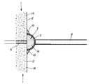
具体的には、図2,図3に示すように、先ず、前記水路用コンクリートブロック1の一方の側壁部1Aの内壁面2に、この水路用コンクリートブロック1の継ぎ目に介在された目地材6に沿ってこの目地材6を覆うように、且つ並設する水路用コンクリートブロック1の各側壁部1Aの端部を跨ぐように半筒状の被覆体5を縦設状態に当接する。
Specifically, as shown in FIG. 2 and FIG. 3, first, a
すると、この被覆体5が、目地材6とこれに隣接する側壁部1Aの内壁面2の端部とを被覆して、この目地材6及び側壁部1Aとの間に断面半円状の給水用間隙3が形成される(図3参照。)。
Then, the
また、本実施例の被覆体5は、長さが1800mmで直径100mmの塩ビ製パイプを半割にしたものを採用している。 Moreover, the covering 5 of the present embodiment employs a PVC pipe having a length of 1800 mm and a diameter of 100 mm that is halved.
次いで、図1に示すように、被覆体5と、水路用コンクリートブロック1の他方の側壁部1Aの内壁面2との間に単管などで構成した複数(図面では二本)の押え体8を架設配設して突っ張ることで被覆体5を前記縦設当接状態に保持し、被覆体5が給水用間隙3に入れた水14の水圧により変位しないように補強する。
Next, as shown in FIG. 1, a plurality of (two in the drawing)
次いで、この被覆体5を、例えばエポキシ系接着剤や急結セメントなどの接着剤10を用いて水路用コンクリートブロック1の側壁部1Aの内壁面2に接着して、この縦設した被覆体5の上部を除いた左右側端部と底側端部との内壁面2並びに目地材6との隙間を埋め、被覆体5上部の開口部を給水口4としてこの給水口4から被覆体5内面と側壁部1Aの内壁面2との間に形成される給水用間隙3に給水し得るようにする。そして給水された状態では、水14が水路用コンクリートブロック1の内壁面2や目地材6に浸込むようにしか漏出しないように構成している。尚、接着剤10は、水路用コンクリートブロック1へのダメージを考慮して選定することが望ましい。
Next, this covering
次いで、この止水した給水用間隙3に、メスシリンダー11を用いて被覆体5の天端付近まで給水した後、24時間放置する。尚、この給水用間隙3内の水14の蒸発を防ぐために油を加えても良い。
Next, water is supplied to the vicinity of the top end of the covering 5 using the graduated cylinder 11 in the
24時間経過後に、再度メスシリンダー11で給水を行い、この際の給水量を測定することで、24時間の減少水量(漏水量)がわかる。測定開始時の給水用間隙3内の水位と、測定終了後の給水用間隙3内の水位との差から、24時間の減水量を求めるようにしても良い。
After 24 hours, water is supplied again with the graduated cylinder 11, and the amount of water decreased (leakage amount) for 24 hours can be determined by measuring the amount of water supplied at this time. From the difference between the water level in the
また、測定中、給水用間隙3が常に満水状態となるように給水を行い、この給水量を測定するようにしても良く、このようにして測定を行うと、給水用間隙3内での水圧が常に一定に保たれるので、より正確な減水量を求めることができると考えられる。
Further, during the measurement, water supply may be performed so that the
また、例えば、給水用間隙3に給水し24時間以上放置するなどして、水路用コンクリートブロック1に予め水14を浸込ませ、この測定箇所が水14の浸込む余地のない水分飽和状態となるようにしてから、改めて給水用間隙3に給水して減水量を測定するようにしても良く、このようにして測定を行うと、水路用コンクリートブロック1への水分の浸込みを考慮せずとも良いため、より正確な目地材6からの減水量を求めることできると考えられる。
In addition, for example, by supplying water into the
この結果得られた減水量値から、一時間あたりの漏水量を算定する。例えば、本実施例では、(減水量)÷((測定時間)×(給水用間隙3の内壁面2並びに目地材6への接触面積))という計算式で算定しているが、この漏水量の算定については、その他にも色々な算定方法が考えられるので、適宜設計変更可能である。
The amount of water leakage per hour is calculated from the water loss value obtained as a result. For example, in this embodiment, the amount of water leakage is calculated by a calculation formula of (water reduction amount) ÷ ((measurement time) × (contact area to the
また、この漏水量の測定を複数箇所で行い、漏水量の平均値を求めるようにしても良い。 In addition, the amount of water leakage may be measured at a plurality of locations, and the average value of the amount of water leakage may be obtained.
測定終了後は、被覆体5を内壁面2から取り外す。
After completion of the measurement, the
尚、本実施例では、図示していないが、被覆体5で水路用コンクリートブロック1の側壁部1Aの内壁面2の一部を被覆して上記同様に漏水測定を行えば、水路用コンクリートブロック1の側壁部1Aからの漏水量(浸込み量)を測定することができる。
In the present embodiment, although not shown in the drawings, if a leak is measured in the same manner as described above by covering a part of the
また、図示していないが、被覆体5を、水路用コンクリートブロック1の底壁部1Bに固定若しくは底壁部1B間の目地材6を覆うように固定して、底壁部1Bの内壁面2の漏水量若しくは底壁部1B間の目地材6からの漏水量を測定することもできる。
Moreover, although not shown in figure, the
本発明の具体的な実施例2について図4に基づいて説明する。 A second embodiment of the present invention will be described with reference to FIG.
本実施例は、前記実施例1において、水路用コンクリートブロック1内壁面2への、被覆体5の固定方法を異ならせた場合である。
The present embodiment is a case where the method for fixing the
具体的には、被覆体5の左右側端部及び底側端部と、内壁面2(側壁部1A)との間に帯状の漏止用バックアップ材12を配設し、被覆体5と水路用コンクリートブロック1の他方側の側壁部1Aの内壁面2との間に複数の押え体8(伸縮構造を有するものでも良い。)を架設配設して突っ張ることで、被覆体5を(バックアップ材12を介して)前記側壁部1Aに縦設状態にして圧着固定した場合を示している。
Specifically, a belt-shaped
また、本実施例では、このバックアップ材12に沿ってこのバックアップ材12の外側から止水材13を盛設することで、縦設した被覆体5の上部を除いた左右側端部及び底側端部と、側壁部1Aの内壁面2及び目地材6との隙間を確実に埋めて止水状態としている。
Further, in this embodiment, the water-stopping
その他は前記実施例1と同様である。 Others are the same as those of the first embodiment.
本発明の具体的な実施例3について図5〜図7に基づいて説明する。 A third embodiment of the present invention will be described with reference to FIGS.
本実施例は、図5に示すように、水路用コンクリートブロック1の継ぎ目に配される目地材6に沿って、一方の側壁部1Aの上部から底壁部1Bを介して他方の側壁部1Aの上部に至るまでの範囲で目地材6を被覆体5で覆って、漏水量を測定した場合を示している。
In the present embodiment, as shown in FIG. 5, along the
具体的には、本実施例の被覆体5は、柔軟性を有する帯状の硬質ビニールシートを採用して構成し、この被覆体5を目地材6に沿って配設すると共にこの被覆体5の長さ方向の中央部を側壁部1Aの内側に弛ませた上で、両側部を目地材6に隣接する側壁部1A及び底壁部1Bの内壁面2に接着剤10を用いて接着固定し、この被覆体5の弛ませた中央部の内側面と目地材6との間の間隙を給水用間隙3としている。尚、例えば、被覆体5の両側部を前記実施例2のようにして圧着固定したり、他の固定手段で固定しても良い。
Specifically, the covering 5 of the present embodiment is configured by adopting a flexible band-shaped hard vinyl sheet, and the
この給水用間隙3の一端を止水すると共に、この給水用間隙3の他端を給水口4としてこの給水口4から給水した後、この給水口4に連結管9を介して加圧ポンプ7を接続し、この加圧ポンプ7により給水用間隙3内に給水して給水用間隙3内を均等に加圧し、この給水用間隙3に臨設する前記水路用コンクリートブロック1の内壁面2と目地材6とに水圧を均等に作用させる。
One end of the
この加圧状態のまま24時間放置し、その後、加圧ポンプ7での給水量を測定することで、24時間の減少水量(漏水量)がわかる。 By leaving it in this pressurized state for 24 hours, and then measuring the amount of water supplied by the pressure pump 7, the amount of reduced water (leakage) for 24 hours can be determined.
本実施例においては、測定箇所の全域に均等な水圧を加えるために、測定箇所の水深などの違いによる漏水量のムラが出にくく、より正確な測定結果(漏水量)を確認できることになる。 In this embodiment, since uniform water pressure is applied to the entire measurement location, unevenness in the amount of leakage due to differences in water depth at the measurement location is unlikely to occur, and a more accurate measurement result (water leakage) can be confirmed.
尚、本実施例では、一方の側壁部1Aの上部から底壁部1Bを介して他方の側壁部1Aの上部に至るまでの範囲全てに被覆体5を被覆し、この範囲の漏水を一括で測定した場合を示したが、側壁部1Aの内壁面2と底壁部1Bの内壁面2との連設部(傾斜箇所)への被覆体5の固定にやや難があることを考慮して、側壁部1Aと底壁部1Bとに別々の被覆体5を被覆して夫々の測定箇所で漏水量を測定するようにしても良い。
In this embodiment, the covering
また、本実施例で示した加圧測定方法は、前記実施例1,2に適用しても良い。 Further, the pressure measurement method shown in the present embodiment may be applied to the first and second embodiments.
また、この加圧測定方法は、強度のない測定対象には不適と考えられるので、測定対象の劣化状況や下地処理の有無などを考慮して行うことが望ましい。 In addition, this pressure measurement method is considered to be unsuitable for a measurement object having no strength, and therefore it is desirable to perform the measurement in consideration of the deterioration state of the measurement object and the presence or absence of a ground treatment.
尚、本発明は、実施例1〜3に限られるものではなく、各構成要件の具体的構成は適宜設計し得るものである。 In addition, this invention is not restricted to Examples 1-3, The concrete structure of each component can be designed suitably.
1 水路用コンクリートブロック
2 内壁面
3 給水用間隙
4 給水口
5 被覆体
6 目地材
7 加圧ポンプ
DESCRIPTION OF SYMBOLS 1 Concrete block for
Claims (4)
Priority Applications (1)
| Application Number | Priority Date | Filing Date | Title |
|---|---|---|---|
| JP2009164255A JP5083996B2 (en) | 2009-07-10 | 2009-07-10 | Water leak measurement method |
Applications Claiming Priority (1)
| Application Number | Priority Date | Filing Date | Title |
|---|---|---|---|
| JP2009164255A JP5083996B2 (en) | 2009-07-10 | 2009-07-10 | Water leak measurement method |
Publications (2)
| Publication Number | Publication Date |
|---|---|
| JP2010090689A JP2010090689A (en) | 2010-04-22 |
| JP5083996B2 true JP5083996B2 (en) | 2012-11-28 |
Family
ID=42253662
Family Applications (1)
| Application Number | Title | Priority Date | Filing Date |
|---|---|---|---|
| JP2009164255A Active JP5083996B2 (en) | 2009-07-10 | 2009-07-10 | Water leak measurement method |
Country Status (1)
| Country | Link |
|---|---|
| JP (1) | JP5083996B2 (en) |
Families Citing this family (6)
| Publication number | Priority date | Publication date | Assignee | Title |
|---|---|---|---|---|
| CN102966075A (en) * | 2012-12-07 | 2013-03-13 | 顾青林 | Self-propelled concrete pipe lining machine |
| CN104674765B (en) * | 2015-03-10 | 2016-08-24 | 扬州大学 | A kind of self-locking eco-concrete irrigation canals and ditches bank protection of embedded haydite |
| CN105568928B (en) * | 2015-12-30 | 2017-07-28 | 中国电建集团北京勘测设计研究院有限公司 | A kind of construction method of compound geomembrane facing slab dam sealing seam |
| CN105672204A (en) * | 2016-03-24 | 2016-06-15 | 中水北方勘测设计研究有限责任公司 | Anti-seepage structure for concrete structural joint |
| RU2671103C2 (en) * | 2016-05-16 | 2018-10-29 | Федеральное государственное бюджетное научное учреждение "Федеральный научный центр агроэкологии, комплексных мелиораций и защитного лесоразведения Российской академии наук" | Anti-filtration lining of channel of meliorative structure from composite blocks-trays |
| JP7110524B2 (en) * | 2018-05-11 | 2022-08-02 | 株式会社大林組 | Test equipment and test method |
Family Cites Families (4)
| Publication number | Priority date | Publication date | Assignee | Title |
|---|---|---|---|---|
| JP3476528B2 (en) * | 1994-02-15 | 2003-12-10 | 日本道路株式会社 | Joint repair materials such as dams |
| JPH09108644A (en) * | 1995-10-13 | 1997-04-28 | Taisei Corp | Method for repairing impervious structure |
| JP3505399B2 (en) * | 1998-08-28 | 2004-03-08 | 古河電気工業株式会社 | Pipe introduction wall assembly member for underground container |
| JP2001031948A (en) * | 1999-07-23 | 2001-02-06 | Nippon Kayaku Co Ltd | Agent and method for preventing water leak |
-
2009
- 2009-07-10 JP JP2009164255A patent/JP5083996B2/en active Active
Also Published As
| Publication number | Publication date |
|---|---|
| JP2010090689A (en) | 2010-04-22 |
Similar Documents
| Publication | Publication Date | Title |
|---|---|---|
| JP5083996B2 (en) | Water leak measurement method | |
| JP5097634B2 (en) | Tunnel waterproof structure and its construction method | |
| CN108411939A (en) | The spliced prefabricated pipe gallery of one kind and its construction method | |
| KR101267432B1 (en) | Non-digging repair method and apparatus for repairing linkage between branch-pipe and main-pipe | |
| KR101245258B1 (en) | Non-digging repair method and apparatus for repairing linkage between branch-pipe and main-pipe | |
| US10077554B2 (en) | Corrosion protection of cables in a concrete structure | |
| KR101186104B1 (en) | Method for repairing expansion joint part between concrete structures using inducing conduct pipe | |
| JP4479575B2 (en) | Watertightness inspection method | |
| CN108106992A (en) | Test about Bond Strength method under the conditions of the infiltration of coating material pressure | |
| CN207597442U (en) | A kind of prefabricated pipe gallery joint waterproof structure | |
| CN112922425B (en) | Non-bottom bolt connection type water tank anti-leakage construction method | |
| CN112969576A (en) | Dual skin structure with gap spacers | |
| US8544505B1 (en) | Pre-stressed concrete pipe | |
| CN209688340U (en) | A kind of pipeline rehabilitation apparatus and system | |
| KR20060134754A (en) | Partial coating waterproof tunnel and there of method | |
| KR101245259B1 (en) | Non-digging repair method and apparatus for repairing linkage between branch-pipe and main-pipe | |
| CN105672373B (en) | Immersed tube tunnel watertight door leakage detection apparatus | |
| CN205875426U (en) | Novel basement antiseep connection structure | |
| KR100756437B1 (en) | Method for Repairing the Pipe of Harden Type | |
| TWI755611B (en) | Pre-embedded perfusion tube set and method of using the same | |
| JP6413043B1 (en) | Drainage joint unit, drainage joint structure equipped with the drainage joint unit, and drainage pipe repair method | |
| CN107700540B (en) | Watertight leakage detection method for detecting immersed tube semi-rigid segment joint waterproof system | |
| JP2001200548A (en) | Forward waterproof method for wall surface of underground structure | |
| CN205475371U (en) | Immersed tube tunnel watertight door leak hunting device | |
| JP2001159136A (en) | Waterproof construction method of earth-retaining wall surface |
Legal Events
| Date | Code | Title | Description |
|---|---|---|---|
| A521 | Request for written amendment filed |
Free format text: JAPANESE INTERMEDIATE CODE: A821 Effective date: 20100217 |
|
| A621 | Written request for application examination |
Free format text: JAPANESE INTERMEDIATE CODE: A621 Effective date: 20100427 |
|
| A977 | Report on retrieval |
Free format text: JAPANESE INTERMEDIATE CODE: A971007 Effective date: 20111129 |
|
| A131 | Notification of reasons for refusal |
Free format text: JAPANESE INTERMEDIATE CODE: A131 Effective date: 20111201 |
|
| A521 | Request for written amendment filed |
Free format text: JAPANESE INTERMEDIATE CODE: A523 Effective date: 20120127 |
|
| TRDD | Decision of grant or rejection written | ||
| A01 | Written decision to grant a patent or to grant a registration (utility model) |
Free format text: JAPANESE INTERMEDIATE CODE: A01 Effective date: 20120802 |
|
| A01 | Written decision to grant a patent or to grant a registration (utility model) |
Free format text: JAPANESE INTERMEDIATE CODE: A01 |
|
| A61 | First payment of annual fees (during grant procedure) |
Free format text: JAPANESE INTERMEDIATE CODE: A61 Effective date: 20120901 |
|
| R150 | Certificate of patent or registration of utility model |
Free format text: JAPANESE INTERMEDIATE CODE: R150 Ref document number: 5083996 Country of ref document: JP Free format text: JAPANESE INTERMEDIATE CODE: R150 |
|
| FPAY | Renewal fee payment (event date is renewal date of database) |
Free format text: PAYMENT UNTIL: 20150914 Year of fee payment: 3 |
|
| R250 | Receipt of annual fees |
Free format text: JAPANESE INTERMEDIATE CODE: R250 |
|
| R250 | Receipt of annual fees |
Free format text: JAPANESE INTERMEDIATE CODE: R250 |
|
| R250 | Receipt of annual fees |
Free format text: JAPANESE INTERMEDIATE CODE: R250 |
|
| R250 | Receipt of annual fees |
Free format text: JAPANESE INTERMEDIATE CODE: R250 |
|
| R250 | Receipt of annual fees |
Free format text: JAPANESE INTERMEDIATE CODE: R250 |
|
| R250 | Receipt of annual fees |
Free format text: JAPANESE INTERMEDIATE CODE: R250 |
|
| R250 | Receipt of annual fees |
Free format text: JAPANESE INTERMEDIATE CODE: R250 |
|
| R250 | Receipt of annual fees |
Free format text: JAPANESE INTERMEDIATE CODE: R250 |
|
| R250 | Receipt of annual fees |
Free format text: JAPANESE INTERMEDIATE CODE: R250 |