JP5083643B2 - Welding equipment for welding shaft-shaped parts to pipe members - Google Patents
Welding equipment for welding shaft-shaped parts to pipe members Download PDFInfo
- Publication number
- JP5083643B2 JP5083643B2 JP2006221703A JP2006221703A JP5083643B2 JP 5083643 B2 JP5083643 B2 JP 5083643B2 JP 2006221703 A JP2006221703 A JP 2006221703A JP 2006221703 A JP2006221703 A JP 2006221703A JP 5083643 B2 JP5083643 B2 JP 5083643B2
- Authority
- JP
- Japan
- Prior art keywords
- pipe member
- welding
- electrode
- axis
- shaft
- Prior art date
- Legal status (The legal status is an assumption and is not a legal conclusion. Google has not performed a legal analysis and makes no representation as to the accuracy of the status listed.)
- Expired - Fee Related
Links
Images


Landscapes
- Resistance Welding (AREA)
- Automatic Assembly (AREA)
Description
この発明は、ボルト,棒材,パイプ材などの軸状部品をパイプ部材に溶接する溶接装置に関している。 The present invention relates to a welding apparatus for welding shaft-shaped parts such as bolts, rods, and pipes to pipe members.
複数の帯状の鋼板をロールフィーダで送り出し、この鋼板を順次溶接で接続し、それからプレス加工を行うものが特開平5−169165号公報に記載されている。
上述のような技術は平板状の鋼板に対する溶接やプレス加工を行うものである。しかしながら、パイプ部材に軸状部品を溶接する場合には、パイプ部材の円筒面に溶接するものであるから、パイプ部材と溶接装置との相対位置を特殊な状態に設定する必要がある。 The above-described technique performs welding or pressing on a flat steel plate. However, when a shaft-like part is welded to the pipe member, the pipe member is welded to the cylindrical surface of the pipe member, so that the relative position between the pipe member and the welding apparatus needs to be set to a special state.
本発明は、上記の問題点を解決するために提供されたもので、パイプ部材の製造機または加工機に溶接装置を組み付けて、パイプ部材の円筒面に正確に軸状部品を溶接することのできる溶接装置の提供を目的とする。 The present invention is provided in order to solve the above-described problems. A welding device is assembled to a pipe member manufacturing machine or a processing machine, and a shaft-like component is accurately welded to a cylindrical surface of the pipe member. An object of the present invention is to provide a welding device that can be used.
請求項1記載の発明は、電極軸線上に固定電極と可動電極が同軸状態で配置された溶接装置を、パイプ部材の製造機または加工機に組み付け、前記固定電極または可動電極に前記軸状部品を保持する受入孔が形成され、溶接装置の電極軸線がパイプ部材の軸線にほぼ直交するように溶接装置が配置され、前記溶接装置の構造形式は、前記固定電極と可動電極が設けられたC型アームを有するCガン形式であり、前記電極軸線がパイプ部材の軸線から離隔するようにするための進退移動機構が溶接装置に設けられ、電極軸線がパイプ部材の軸線から離隔している状態のときに前記受入孔に軸状部品を供給する部品供給装置が配置されていることを特徴とする軸状部品をパイプ部材に溶接する溶接装置である。According to a first aspect of the present invention, a welding device in which a fixed electrode and a movable electrode are coaxially arranged on an electrode axis is assembled to a pipe member manufacturing machine or a processing machine, and the shaft-like component is attached to the fixed electrode or the movable electrode. The welding apparatus is disposed so that the electrode axis of the welding apparatus is substantially perpendicular to the axis of the pipe member, and the welding apparatus is structured in such a manner that the fixed electrode and the movable electrode are provided. state Ri C gun type der with mold arm, forward and backward movement mechanism for the electrode axes so as to apart from the axis of the pipe member is provided in the welding apparatus, electrodes axis is spaced from the axis of the pipe member A welding apparatus for welding a shaft-shaped component to a pipe member , wherein a component supply device for supplying the shaft-shaped component to the receiving hole is disposed .
パイプ部材の製造機または加工機に組み付けられた溶接装置は、その電極軸線がパイプ部材の軸線にほぼ直交するように配置され、これによって前記受入孔に保持された軸状部品はその軸線がパイプ部材の軸線に直交する状態となる。したがって、軸状部品の端部がパイプ部材の円筒面に加圧されても、その加圧力が作用する箇所すなわち軸状部品の軸線が円周方向に片寄ったりずれたりすることがなく、前記加圧力が正確に円筒面に作用し、その状態で溶接電流が通電されて、確実な溶接がなされる。軸状部品は受入孔に挿入された状態で保持されるので、軸状部品と電極との一体性が良好なものとなり、しかも電極と軸状部品との同軸状態が正確に設定することができ、円筒面に対する加圧や通電にとって効果的である。 The welding device assembled in the pipe member manufacturing machine or processing machine is arranged so that the electrode axis thereof is substantially perpendicular to the axis of the pipe member, so that the shaft-like component held in the receiving hole has its axis aligned with the pipe. The state is perpendicular to the axis of the member. Therefore, even if the end of the shaft-shaped component is pressed against the cylindrical surface of the pipe member, the portion where the pressure is applied, that is, the axis of the shaft-shaped component is not shifted or displaced in the circumferential direction, and the pressure is not increased. The pressure acts on the cylindrical surface accurately, and a welding current is applied in that state, so that reliable welding is performed. Since the shaft-like component is held in the state of being inserted into the receiving hole, the integrity of the shaft-like component and the electrode becomes good, and the coaxial state between the electrode and the shaft-like component can be set accurately. It is effective for pressurizing and energizing the cylindrical surface.
前記電極軸線がパイプ部材の軸線から離隔するようにするための進退移動機構が溶接装置に設けられ、電極軸線がパイプ部材の軸線から離隔している状態のときに前記受入孔に軸状部品を供給する部品供給装置が配置されている。 Forward and backward movement mechanism for pre Symbol electrode axes so as to apart from the axis of the pipe member is provided in the welding apparatus, the shaft-like component to the receiving hole in a state where the electrode axis is spaced from the axis of the pipe member the that are located component supply device supplies.
このような構成により、電極軸線がパイプ部材の軸線からずれた状態になるので、電極の端部が開放された状態になる。この開放された箇所から前記受入孔に軸状部品を挿入することができる。したがって、パイプ部材に干渉することなく軸状部品の供給ができて、装置の動作が円滑に実行できる。 With such a configuration, since the electrode axis is shifted from the axis of the pipe member, the end of the electrode is opened. A shaft-like component can be inserted into the receiving hole from the opened portion. Accordingly, the shaft-shaped component can be supplied without interfering with the pipe member, and the operation of the apparatus can be executed smoothly.
請求項2記載の発明は、前記溶接装置がパイプ部材の長手方向に沿って移動できるように構成した請求項1記載の軸状部品をパイプ部材に溶接する溶接装置である。 A second aspect of the present invention is a welding apparatus for welding a shaft-like component according to the first aspect of the present invention, wherein the welding apparatus is configured to move along the longitudinal direction of the pipe member.
このように溶接装置がパイプ部材の長手方向に移動できるので、パイプ部材の所定位置に軸状部品を溶接することができる。そして、加圧や通電の溶接動作中は電極とパイプ部材との相対位置が変わらないようにしなければならないのであるが、上記のように溶接装置が移動できるので、パイプ部材の送給に同期させて前記相対位置を正確に維持したまま正常な溶着が達成される。 Thus, since the welding apparatus can move in the longitudinal direction of the pipe member, the shaft-like component can be welded to a predetermined position of the pipe member. The relative position between the electrode and the pipe member must not be changed during the pressurizing or energizing welding operation. However, since the welding apparatus can move as described above, it is synchronized with the feeding of the pipe member. Thus, normal welding is achieved while maintaining the relative position accurately.
請求項3記載の発明は、前記パイプ部材が所定角度回転するように構成した請求項1または請求項2記載の軸状部品をパイプ部材に溶接する溶接装置である。 According to a third aspect of the present invention, there is provided a welding apparatus for welding the shaft-like component according to the first or second aspect, wherein the pipe member is rotated by a predetermined angle.
このようにパイプ部材が所定角度回転できるので、パイプ部材の円周方向のどの箇所に対しても軸状部品を確実に溶接できる。 Since the pipe member can rotate by a predetermined angle in this way, the shaft-like component can be reliably welded to any location in the circumferential direction of the pipe member.
請求項4記載の発明は、前記溶接装置が製造機または加工機におけるパイプ部材の送り速度と等速でパイプ部材の長手方向に沿って移動するように構成した請求項1〜請求項3のいずれかに記載の軸状部品をパイプ部材に溶接する溶接装置である。 Fourth aspect of the present invention, any the welding apparatus according to claim 1 to claim 3 which is configured to move along the longitudinal direction of the pipe member at a feed rate and a constant velocity of the pipe member in the making machine or processing machine It is a welding apparatus which welds the shaft-shaped components as described above to a pipe member.
加圧や通電の溶接動作中は電極とパイプ部材との相対位置が変わらないようにしなければならないのであるが、上記のように溶接装置が製造機または加工機におけるパイプ部材の送り速度と等速で移動するので、パイプ部材の送給に同期させて前記相対位置を正確に維持したまま正常な溶着が達成される。 The relative position between the electrode and the pipe member must not be changed during the pressurizing or energizing welding operation. However, as described above, the welding apparatus operates at the same speed as the feed speed of the pipe member in the manufacturing machine or processing machine. Therefore, normal welding is achieved while maintaining the relative position accurately in synchronization with the feeding of the pipe member.
つぎに、本発明の軸状部品をパイプ部材に溶接する溶接装置を実施するための最良の形態を説明する。 Next, the best mode for carrying out a welding apparatus for welding the shaft-like part of the present invention to a pipe member will be described.
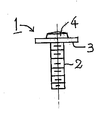
本発明における軸状部品としては、ボルト,棒材,パイプ材などのように種々なものがある。この実施例では、図5に示す鉄製のプロジェクションボルトである。このプロジェクションボルト1は、軸部であるボルト軸2と、このボルト軸2と一体の円形のフランジ部3と、このフランジ部3の中央部に設けられた円形の溶着用突起4から構成されている。なお、このプロジェクションボルトを単にボルトと表現する場合もある。 There are various types of shaft-like parts in the present invention such as bolts, rods, pipes and the like. In this embodiment, the iron projection bolt shown in FIG. The projection bolt 1 includes a
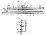
図1および図2は、実施例1を示す。 1 and 2 show Example 1. FIG.
図1は、パイプ部材5の製造機6に溶接装置7,8を組み付けたものである。この製造機6は一般的に採用されている形式のものであり、コイル10から帯状の鋼板9が連続的に引き出され、フォーミングロール11,12によって管状に成型され、シーム溶接装置13によって継ぎ目が溶接されてパイプ部材5とされる。この製造機6の換わりに、パイプ部材5を曲げる曲げ加工機であってもよい。 FIG. 1 shows a
真っ直ぐに延びているパイプ部材5に沿って基台14が配置されている。基台14の端部に定置式の溶接装置7が設置してあり、その隣に移動式の溶接装置8が設置してある。両溶接装置7,8は、プロジェクションボルト1をパイプ部材5の円筒面に電気抵抗溶接をするもので、定置式の溶接装置7はパイプ部材5を停止させて溶接する場合に使用され、また、移動式の溶接装置8はパイプ部材5の移動中に溶接する場合に使用される。 A
両溶接装置7,8の構造形式は同様なものでよく、また、種々な構造形式を採用することができるが、ここに例示したものは、図2(A)に示すように、Cガン形式である。C型アーム15に固定電極16と可動電極17が設けられ、両電極は電極軸線O−O上に配置されている。可動電極17はC型アーム15の上部に取付けられたエアシリンダ18によって進退動作をするようになっている。鉛直方向に起立している支持ロッド19がエアシリンダ18に沿ってC型アーム15に固定され、この支持ロッド19が摺動自在な状態で支持ブロック20を貫通している。また、エアシリンダ18と支持ロッド19は上端部において連結部材21によって結合されている。そして、支持ブロック20と連結部材21との間に圧縮コイルスプリング22が配置されている。 The structural types of the
支持ブロック20は連結部材23を介して支持ブロック24に結合されており、この支持ブロック24を水平方向に配置された支持ロッド25が摺動自在な状態で貫通している。支持ロッド25の両端はコ字型の支持ブラケット26に結合され、この支持ブラケット26が支持ブロック27に固定されている。そして、支持ロッド25の軸線は、後述のパイプ部材5の軸線と直角に食い違った状態で配置されている。 The
定置式の溶接装置7においては、この支持ブロック27が基台14に結合されていて、移動できない構造になっている。 In the stationary welding apparatus 7, the
他方、移動式の溶接装置8は、前記支持ブロック27が移動機構29を介して基台14に取り付けられている。この移動機構29によって、溶接装置8がパイプ部材5の長手方向に沿って移動できるようになっている。このような移動機構29は、一般的に採用されている種々な機構で実現することができる。 On the other hand, in the
例えば、図1や図2(A)に示すように、基台14上に設置されたガイドレール30に、支持ブロック27に固定されたスライダ31を組み付けて、支持ブロック27を進退可能な状態で支持し、基台14側に取付けたエアシリンダ32の進退出力をピストンロッド33を介して支持ブロック27に伝えるようにする。こうすることにより、エアシリンダの進退動作によって支持ブロック27が前記ガイドレール30に沿って移動するのである。あるいは、進退動作をエアシリンダで行う換わりに、ラックピニオン機構を採用することもできる。 For example, as shown in FIGS. 1 and 2A, a
支持ブロック24を左右に進退させる進退移動機構35は、図2(C)に示されている。本機構35は、一般的に採用されている種々な機構で実現することができる。例えば、支持ロッド25の長手方向に進退出力をするエアシリンダ36を支持ブラケット26に取付け、このエアシリンダ36のピストンロッド37を支持ブロック24に結合する。 The forward / backward moving
溶接装置7,8の鉛直方向に延びる電極軸線O−Oと、水平方向に延びているパイプ部材5の軸線34とは、直交している。前記軸線34は、図2の紙面に対して垂直方向になっている。 The electrode axis OO extending in the vertical direction of the
上記のように、移動機構29のエアシリンダ32によって溶接装置8がパイプ部材5の長手方向に移動する。この移動速度はエアシリンダの動作速度を制御することによって行われ、パイプ部材5の送り速度と等速にするためには、製造機6の駆動モータの送り速度とエアシリンダ32の送り速度とが同期するように、制御装置を用いて制御される。このような制御装置は、一般的なものを採用することによって、容易に実施することができる。 As described above, the
図2(A)に示すように、パイプ部材5の上下に固定電極16と可動電極17が接近した状態で存在している場合には、電極にボルト1を供給するスペースを確保するために、両電極16,17をずらして電極端部を開放した状態にすることが望ましい。すなわち、電極軸線O−Oをパイプ部材5の軸線34から離隔させることが望ましい。そのために前記進退移動機構35の動作により、支持ブロック24を同図の左方に移動させて、両電極16,17の間からパイプ部材5を相対的に退避した状態とする。このようにして固定電極16の端部が開放される。 As shown in FIG. 2A, in the case where the fixed
図2(B)に示すように、進退移動機構35によってC型アーム15全体が左方に移動する。これによって電極軸線O−Oはパイプ部材5の軸線34から距離Lだけ離隔し、固定電極16の端部の上側と、可動電極17の端部の下側が開放された状態になる。この実施例では固定電極16の側にボルト1が保持される。そのために、固定電極16の電極軸線O−Oと同軸の状態で受入孔38が設けてある。 As shown in FIG. 2B, the entire C-
前記受入孔38にボルト1のボルト軸2を挿入する方法すなわち部品供給装置としては、斜め上方から進出してくる供給ロッドにボルト1を保持して、供給ロッドの移動によって挿入したり、水平方向に進退する供給ロッドにスクエアーモーションを行わせて挿入したりする方法が採用できる。ここでは、図2(B)に示すように、後者の場合が採用されている。 As a method of inserting the
部品供給装置39は、水平方向に進退出力をするエアシリンダ40に供給ロッド41が結合され、その先端部に下向きの保持面42が形成されている。供給ロッド41の先端部に永久磁石43が取付けられ、その吸引力でボルト1が保持されている。ボルト軸2を下降させるために、エアシリンダ40全体を昇降するエアシリンダ44が静止部材45に取り付けられている。このエアシリンダ44のピストンロッド46にエアシリンダ40が結合されている。 In the component supply device 39, a supply rod 41 is coupled to an
部品供給装置39の動作を説明する。図2(B)は、ボルト軸2が電極軸線O−Oと同軸になった箇所で供給ロッド41の進出が停止した状態を示している。この状態からエアシリンダ44が縮小すると、ボルト軸2が受入孔38内に挿入される。この挿入された状態で供給ロッド41が後退すると、ボルト1は受入孔38内に残留しボルト供給が完了する。 The operation of the component supply device 39 will be described. FIG. 2B shows a state in which the advancement of the supply rod 41 is stopped at a position where the
供給ロッド41が後退しているときにボルト1が保持面42に供給される。そのための供給管47が静止部材45に固定してある。この供給管47はパーツフィーダ48から延びてきている。なお、供給管47が供給ロッド41に干渉する場合には、エアシリンダ40に固定したブラケット(図示していない)に供給管47を固定して、供給管47と供給ロッド41とが一体になって昇降するように構成するのが望ましい。 The bolt 1 is supplied to the holding surface 42 when the supply rod 41 is retracted. A
成型されたパイプ部材5に所定個数のボルト1が溶接されると、所定の長さで切断される。符号28は、そのパイプ切断機である。切断されたパイプ部品37は傾斜シュータ49を経て次工程に移送される。 When a predetermined number of bolts 1 are welded to the molded pipe member 5, it is cut at a predetermined length.
上述の実施例1の作用効果は、つぎのとおりである。 The operational effects of the first embodiment are as follows.
パイプ部材5の製造機6に組み付けられた溶接装置7,8は、その電極軸線O−Oがパイプ部材5の軸線34にほぼ直交するように配置され、これによって前記受入孔38に保持されたボルト1はその軸線がパイプ部材5の軸線に直交する状態となる。したがって、ボルト1の端部がパイプ部材5の円筒面に加圧されても、その加圧力が作用する箇所すなわちボルト軸2の軸線が円周方向に片寄ったりずれたりすることがなく、前記加圧力が正確に円筒面に作用し、その状態で溶接電流が通電されて、確実な溶接がなされる。ボルト1は受入孔38に挿入された状態で保持されるので、ボルト1と固定電極16との一体性が良好なものとなり、しかも固定電極16とボルト1との同軸状態が正確に設定することができ、円筒面に対する加圧や通電にとって効果的である。 The
前記電極軸線O−Oがパイプ部材5の軸線34から離隔するようにするための進退移動機構35が溶接装置7,8に設けられ、電極軸線O−Oがパイプ部材5の軸線34から離隔している状態のときに前記受入孔38にボルト1を供給する部品供給装置39が配置されている。 An advancing / retreating
このような構成により、電極軸線O−Oがパイプ部材5の軸線34からずれた状態になるので、固定電極16の端部が開放された状態になる。この開放された箇所から前記受入孔38にボルト1を挿入することができる。したがって、パイプ部材5に干渉することなくボルト1の供給ができて、装置の動作が円滑に実行できる。 With such a configuration, since the electrode axis OO is shifted from the
前記溶接装置8がパイプ部材5の長手方向に沿って移動できるように構成した。 The
このように溶接装置8がパイプ部材5の長手方向に移動できるので、パイプ部材5の所定位置にボルト1を溶接することができる。そして、加圧や通電の溶接動作中は両電極16,17とパイプ部材5との相対位置が変わらないようにしなければならないのであるが、上記のように溶接装置8が移動できるので、パイプ部材5の送給に同期させて前記相対位置を正確に維持したまま正常な溶着が達成される。 Since the
前記溶接装置8が製造機6におけるパイプ部材5の送り速度と等速でパイプ部材5の長手方向に沿って移動するように構成した。 The
加圧や通電の溶接動作中は固定電極16,可動電極17とパイプ部材5との相対位置が変わらないようにしなければならないのであるが、上記のように溶接装置8が製造機6におけるパイプ部材5の送り速度と等速で移動するので、パイプ部材5の送給に同期させて前記相対位置を正確に維持したまま正常な溶着が達成される。 The relative positions of the fixed
図3は、実施例2を示す。 FIG. 3 shows a second embodiment.
この実施例は、2つのパイプ部材5A,5Bを溶接で接合する接合機50に溶接装置8が組み付けられた場合である。溶接装置8の構成は実施例1で説明したものと同じである。左右に配置された支柱51,52の上端にパイプ部材5A,5Bを回転可能な状態で支持するチャック部53,54が設けてある。そして、パイプ部材5A,5Bの中央側端部は、支持基台14A上に配置した回転可能なチャック部55,56を貫通させてある。これらのチャック部55,56は、支持基台14Aに結合した回転駆動部57,58に取付けられている。これらの回転駆動部57,58は、電動モータなどの駆動手段によって構成され、チャック部55,56を回転させる。 In this embodiment, the
パイプ部材5Aと5Bが突き合わされた部分は符号59で示され、この部分59が溶接で接合される。溶接方法としては摩擦溶接やレーザー溶接などのいろいろなものが採用できる。ここでは後者のレーザー溶接である。符号60によってレーザー溶接装置の溶接部が示されている。左側の溶接装置8には可動電極17にボルト1が保持されるようになっており、右側の溶接装置8には固定電極16にボルト1が保持されるようになっている。 A portion where the
前記回転駆動部57,58によってパイプ部材5A,5Bを所定角度回転させて、プロジェクションボルト1を円筒面に溶接する。また、両溶接装置8,8をパイプ部材5A,5Bの長手方向に移動させて所定の位置にボルト1を溶接する。それ以外の構成は先の実施例と同じなので、同様な機能の部材には同一の符号が記載してある。 The
このようにパイプ部材5A,5Bが所定角度回転できるので、パイプ部材5A,5Bの円周方向のどの箇所に対してもボルト1を確実に溶接できる。さらに、溶接装置8,8をパイプ部材5A,5Bの軸方向に移動させることにより、ボルト1をパイプ部材5A,5Bの軸方向と回転方向の任意の箇所に溶接することができて、溶接位置の精度向上や溶接工程の効率向上にとって効果的である。 Since the
図4は、実施例3を示す。 FIG. 4 shows a third embodiment.
図4(A)は、装置全体の側面図であり、同図(B)はその正面図である。 FIG. 4A is a side view of the whole apparatus, and FIG. 4B is a front view thereof.
この実施例は、パイプ部材5をその軸方向に進退させるとともに、回転させてボルト1を溶接するものである。ガイドレール62に組み付けたスライダ63に支持台64が取付けられ、この支持台64の両側にパイプ部材5を支持するチャック部65,66が配置されている。左側のチャック部66に回転駆動部67が設けてある。 In this embodiment, the pipe member 5 is advanced and retracted in the axial direction, and the bolt 1 is welded by rotating it. A
この実施例では、パイプ部材5が進退と回転をするので、定置式の溶接装置7が配置されている。それ以外の構成は先の各実施例と同じなので、同様な機能の部材には同一の符号が記載してある。 In this embodiment, since the pipe member 5 moves forward and backward, a stationary welding device 7 is arranged. Since other configurations are the same as those of the previous embodiments, members having the same function are denoted by the same reference numerals.
このような構成により、パイプ部材5に回転と進退動作を付与して所定の箇所にボルト1を溶接する。このように回転と進退動作を複合させているので、ボルト1の溶接箇所が正確に求められるという効果がある。それ以外の作用効果は、先の各実施例と同じである。 With such a configuration, the pipe member 5 is rotated and moved back and forth, and the bolt 1 is welded to a predetermined location. Since the rotation and the advancing / retreating operation are combined in this way, there is an effect that the welding location of the bolt 1 can be accurately obtained. Other functions and effects are the same as those of the previous embodiments.
上述の実施例においては各種のエアシリンダが採用されているが、これに換えて進退出力をする電動モータを採用してもよい。さらに、上述のような動作を行わせるためには、図示していないが、通常のシーケンサーのような制御装置や、センサーや、制御装置によって動作する空気切換弁などを用いて容易に行うことができる。 Although various air cylinders are employed in the above-described embodiments, an electric motor that performs forward / backward output may be employed instead. Furthermore, in order to perform the operation as described above, although not shown, it can be easily performed using a control device such as a normal sequencer, a sensor, an air switching valve operated by the control device, or the like. it can.
上述のように、本発明によれば、パイプ部材の製造機または加工機に溶接装置を組み付けて、パイプ部材の円筒面に正確に軸状部品を溶接することのできるので、自動車の車体溶接工程や、家庭電化製品の板金溶接工程などの広い産業分野で利用できる。 As described above, according to the present invention, a welding device can be assembled to a pipe member manufacturing machine or processing machine, and a shaft-shaped part can be accurately welded to the cylindrical surface of the pipe member. And can be used in a wide range of industrial fields such as sheet metal welding processes for home appliances.
1 プロジェクションボルト
5 パイプ部材
5A パイプ部材
5B パイプ部材
6 製造機
7 溶接装置
8 溶接装置
14 基台
14A 基台
16 固定電極
17 可動電極
29 移動機構
O−O 電極軸線
34 パイプ部材の軸線
35 進退移動機構
38 受入孔
39 部品供給装置
50 接合機
57 回転駆動部
58 回転駆動部
60 溶接部
67 回転駆動部DESCRIPTION OF SYMBOLS 1 Projection bolt 5
Claims (4)
Priority Applications (1)
| Application Number | Priority Date | Filing Date | Title |
|---|---|---|---|
| JP2006221703A JP5083643B2 (en) | 2006-07-18 | 2006-07-18 | Welding equipment for welding shaft-shaped parts to pipe members |
Applications Claiming Priority (1)
| Application Number | Priority Date | Filing Date | Title |
|---|---|---|---|
| JP2006221703A JP5083643B2 (en) | 2006-07-18 | 2006-07-18 | Welding equipment for welding shaft-shaped parts to pipe members |
Publications (2)
| Publication Number | Publication Date |
|---|---|
| JP2008023592A JP2008023592A (en) | 2008-02-07 |
| JP5083643B2 true JP5083643B2 (en) | 2012-11-28 |
Family
ID=39114764
Family Applications (1)
| Application Number | Title | Priority Date | Filing Date |
|---|---|---|---|
| JP2006221703A Expired - Fee Related JP5083643B2 (en) | 2006-07-18 | 2006-07-18 | Welding equipment for welding shaft-shaped parts to pipe members |
Country Status (1)
| Country | Link |
|---|---|
| JP (1) | JP5083643B2 (en) |
Cited By (1)
| Publication number | Priority date | Publication date | Assignee | Title |
|---|---|---|---|---|
| KR101680565B1 (en) * | 2015-03-24 | 2016-11-29 | 주식회사 성우하이텍 | Roll Forming Method |
Families Citing this family (2)
| Publication number | Priority date | Publication date | Assignee | Title |
|---|---|---|---|---|
| WO2011005586A2 (en) * | 2009-06-24 | 2011-01-13 | Buttress David G | Apparatus and method for joining solar receiver tubes |
| WO2011025925A2 (en) | 2009-08-30 | 2011-03-03 | David Buttress | Apparatus and method for field welding solar receiver tubes |
Family Cites Families (4)
| Publication number | Priority date | Publication date | Assignee | Title |
|---|---|---|---|---|
| JPH06238463A (en) * | 1993-02-13 | 1994-08-30 | Yoshitaka Aoyama | Method and equipment for welding projection bolt or the like to circular pipe |
| JPH06254642A (en) * | 1993-03-04 | 1994-09-13 | Mitsubishi Heavy Ind Ltd | Production of tube with spiral fin |
| JP3790887B2 (en) * | 2000-07-15 | 2006-06-28 | 好高 青山 | Projection bolt welding equipment |
| JP2006159252A (en) * | 2004-12-07 | 2006-06-22 | Fuji Heavy Ind Ltd | Resistance welding structure and resistance welding method for pipe and plate material. |
-
2006
- 2006-07-18 JP JP2006221703A patent/JP5083643B2/en not_active Expired - Fee Related
Cited By (1)
| Publication number | Priority date | Publication date | Assignee | Title |
|---|---|---|---|---|
| KR101680565B1 (en) * | 2015-03-24 | 2016-11-29 | 주식회사 성우하이텍 | Roll Forming Method |
Also Published As
| Publication number | Publication date |
|---|---|
| JP2008023592A (en) | 2008-02-07 |
Similar Documents
| Publication | Publication Date | Title |
|---|---|---|
| US9808883B2 (en) | Dual ultrasonic welder | |
| JP2014221482A (en) | Seam welding method and seam welding device | |
| JP3906404B2 (en) | Parts welding equipment | |
| JP2017209721A (en) | Horizontal automatic welder | |
| JP5365900B2 (en) | Projection nut welding equipment | |
| CN108356458A (en) | Rotatable three axis real-time tracking welders being symmetrically welded | |
| JP5083643B2 (en) | Welding equipment for welding shaft-shaped parts to pipe members | |
| WO2003002288A1 (en) | Method and device for welding projection bolt | |
| JP6191938B2 (en) | Multi-point supply device for perforated parts | |
| JP2013035033A (en) | Spot welding apparatus | |
| CA2345022C (en) | Projection bolt welding system | |
| KR101868970B1 (en) | Machine for welding helical wing on shaft of helical pile | |
| JP2014226673A (en) | Resistance welding device | |
| JP2012196703A (en) | Spot welding method and spot welding equipment | |
| CN119635141A (en) | A self-fixing automatic welding equipment for construction engineering | |
| JP2011036910A (en) | Tig welding machine | |
| JP3209159U (en) | Portable spot welding gun | |
| JP2002224826A (en) | Cylindrical fillet welding equipment | |
| JPH0671428A (en) | Automatic brazing welder | |
| JPS6239079B2 (en) | ||
| JP2007196252A (en) | Welding torch | |
| JP4501138B2 (en) | Projection welding equipment | |
| JP3885212B2 (en) | Welding unit device | |
| JP4849248B2 (en) | Parts supply device for electric resistance welding machine | |
| JP5057033B2 (en) | Parts supply device for electric resistance welding machine |
Legal Events
| Date | Code | Title | Description |
|---|---|---|---|
| A621 | Written request for application examination |
Free format text: JAPANESE INTERMEDIATE CODE: A621 Effective date: 20080130 |
|
| A977 | Report on retrieval |
Free format text: JAPANESE INTERMEDIATE CODE: A971007 Effective date: 20090612 |
|
| A131 | Notification of reasons for refusal |
Free format text: JAPANESE INTERMEDIATE CODE: A131 Effective date: 20110308 |
|
| A521 | Request for written amendment filed |
Free format text: JAPANESE INTERMEDIATE CODE: A523 Effective date: 20110502 |
|
| A131 | Notification of reasons for refusal |
Free format text: JAPANESE INTERMEDIATE CODE: A131 Effective date: 20111206 |
|
| A521 | Request for written amendment filed |
Free format text: JAPANESE INTERMEDIATE CODE: A523 Effective date: 20120118 |
|
| TRDD | Decision of grant or rejection written | ||
| A01 | Written decision to grant a patent or to grant a registration (utility model) |
Free format text: JAPANESE INTERMEDIATE CODE: A01 Effective date: 20120807 |
|
| A01 | Written decision to grant a patent or to grant a registration (utility model) |
Free format text: JAPANESE INTERMEDIATE CODE: A01 |
|
| A61 | First payment of annual fees (during grant procedure) |
Free format text: JAPANESE INTERMEDIATE CODE: A61 Effective date: 20120823 |
|
| R150 | Certificate of patent or registration of utility model |
Ref document number: 5083643 Country of ref document: JP Free format text: JAPANESE INTERMEDIATE CODE: R150 Free format text: JAPANESE INTERMEDIATE CODE: R150 |
|
| FPAY | Renewal fee payment (event date is renewal date of database) |
Free format text: PAYMENT UNTIL: 20150914 Year of fee payment: 3 |
|
| R250 | Receipt of annual fees |
Free format text: JAPANESE INTERMEDIATE CODE: R250 |
|
| LAPS | Cancellation because of no payment of annual fees |