JP5083102B2 - Control device for air treatment equipment - Google Patents
Control device for air treatment equipment Download PDFInfo
- Publication number
- JP5083102B2 JP5083102B2 JP2008200483A JP2008200483A JP5083102B2 JP 5083102 B2 JP5083102 B2 JP 5083102B2 JP 2008200483 A JP2008200483 A JP 2008200483A JP 2008200483 A JP2008200483 A JP 2008200483A JP 5083102 B2 JP5083102 B2 JP 5083102B2
- Authority
- JP
- Japan
- Prior art keywords
- air
- state
- control unit
- fan
- blower fan
- Prior art date
- Legal status (The legal status is an assumption and is not a legal conclusion. Google has not performed a legal analysis and makes no representation as to the accuracy of the status listed.)
- Expired - Fee Related
Links
Images


Classifications
-
- Y—GENERAL TAGGING OF NEW TECHNOLOGICAL DEVELOPMENTS; GENERAL TAGGING OF CROSS-SECTIONAL TECHNOLOGIES SPANNING OVER SEVERAL SECTIONS OF THE IPC; TECHNICAL SUBJECTS COVERED BY FORMER USPC CROSS-REFERENCE ART COLLECTIONS [XRACs] AND DIGESTS
- Y02—TECHNOLOGIES OR APPLICATIONS FOR MITIGATION OR ADAPTATION AGAINST CLIMATE CHANGE
- Y02B—CLIMATE CHANGE MITIGATION TECHNOLOGIES RELATED TO BUILDINGS, e.g. HOUSING, HOUSE APPLIANCES OR RELATED END-USER APPLICATIONS
- Y02B30/00—Energy efficient heating, ventilation or air conditioning [HVAC]
- Y02B30/70—Efficient control or regulation technologies, e.g. for control of refrigerant flow, motor or heating
Landscapes
- Ventilation (AREA)
- Air Conditioning Control Device (AREA)
- Air Humidification (AREA)
Description
本発明は、送風ファンを備えた空気処理機器の制御装置に関する。 The present invention relates to a control device for an air treatment device including a blower fan.
従来の空気清浄機または加湿機などの空気処理機器においては、ダストセンサまたは湿度センサの検知値に応じて、送風機の回転数を制御している。(例えば、特許文献1参照。)
従来の空気清浄機または加湿機などの空気処理機器の自動運転モードにあっては、検知した室内空気の汚れまたは相対湿度に応じて、自動で送風ファンの回転数を判定し、汚れが多ければ、送風量を増やすために回転数を上げ、汚れが少なけれ回転数を下げたり、乾燥していれば加湿量を増やすために回転数を上げ、湿度が上がれば加湿が不要となるために回転数を下げたり、またはファンを停止するなどの動作を行っていた。このような運転は、あくまで汚れや湿度に対応した制御であるため、機器の運転時間を通じて送風ファン駆動用モーターが消費する電力と相関する制御は特に行われておらず、長時間の運転が想定される機器であるにもかかわらず、省エネの面で考慮がなされていないという問題があった。 In the automatic operation mode of conventional air processing equipment such as air purifiers or humidifiers, the rotational speed of the blower fan is automatically determined according to the detected indoor air contamination or relative humidity. Increase the rotation speed to increase the air flow, decrease the rotation speed if there is little dirt, increase the rotation speed to increase the amount of humidification if it is dry, and if the humidity increases, the rotation speed becomes unnecessary. The operation such as lowering or stopping the fan was performed. Since such operation is only control corresponding to dirt and humidity, control that correlates with the power consumed by the blower fan drive motor throughout the operation time of the device is not particularly performed, and long-term operation is assumed. In spite of the equipment being used, there has been a problem that no consideration has been given to energy saving.
本発明は、自動運転時に消費電力量を低く抑え、省エネ効果の高い空気処理機器を提供することを目的としている。 It is an object of the present invention to provide an air treatment device that suppresses power consumption during automatic operation and has a high energy saving effect.
上記目的を達成するために、本発明の空気処理機器においては、室内空気の吸込口および処理空気の吹出口と、送風ファンと、送風ファン駆動用モーターと、空気の汚れまたは湿度を検知する検知手段と、空気の状態に応じて自動で送風ファン回転数を決定する制御部とを備えた空気処理機器において、前記制御部は、前記検知手段の検知信号に基づき前記制御部が前記モーターの回転数を制御する自動運転時において、ファン回転数あたりのモーターの消費電力が低い回転数域を使用するようにしたものである。 In order to achieve the above object, in the air treatment device of the present invention, the indoor air suction port and the treatment air blowout port, the blower fan, the blower fan driving motor, and the detection for detecting dirt or humidity of the air And an air processing device having a control unit that automatically determines the rotational speed of the blower fan according to the state of the air. The control unit is configured so that the control unit rotates the motor based on a detection signal of the detection unit. In the automatic operation for controlling the number, the rotation speed range where the power consumption of the motor per fan rotation speed is low is used.
上記制御は、該運転モードが選択されたときには、機器本体に設けられたLEDなどを用いた表示部を減光または消灯する。 In the above control, when the operation mode is selected, a display unit using an LED or the like provided in the device main body is dimmed or turned off.
また、上記制御に加え、空気の汚れが所定の値を下回るか、または湿度が所定の値を超えたとき等のように、目的とする空気の状態が予め定めた状態になった場合には、空気の汚れや湿度等を検知する検知手段の通電を間欠とする。 In addition to the above control, when the target air condition is in a predetermined state, such as when air pollution is below a predetermined value, or when the humidity exceeds a predetermined value, etc. The energization of the detecting means for detecting air dirt, humidity, etc. is intermittent.
また、検知した空気の汚れと湿度の値を組合せて判定し、送風ファンの回転数を決定する制御とし、使用者の操作は簡単で単純なものとする。 Further, the control is performed by determining the combination of the detected air dirt and humidity and determining the rotational speed of the blower fan, and the user's operation is simple and simple.
本発明は、以上説明したように構成されているので、以下に記載されるような効果を奏する。 Since the present invention is configured as described above, the following effects can be obtained.
空気の汚れや湿度等のような空気の状態に応じて自動で送風ファンの駆動用モータの回転数を制御する自動運転モードにおいて、送風ファンの回転数あたりの送風ファン駆動用モーターの消費電力が少ない回転数域を用いる制御とすることで、使用者が体感する効果を損なうことなく、消費電力量を低く抑えることができる。 In the automatic operation mode that automatically controls the rotation speed of the blower fan drive motor according to the air condition such as air dirt and humidity, the power consumption of the blower fan drive motor per rotation speed of the blower fan is By using the control using a small number of revolutions, the power consumption can be kept low without impairing the effect experienced by the user.
また、該自動運転を選択時には、機器の表示部を減光または消灯することで、より消費電力量の少ない運転を行うことができる。 In addition, when the automatic operation is selected, it is possible to perform operation with less power consumption by dimming or turning off the display portion of the device.
また、該自動運転を選択時に、目的とする空気の状態が所定の状態になった場合、例えば空気の汚れが所定の値を下回るか、または湿度が所定の値を超えたときには、そのような空気の状態を検知する検知手段の通電を間欠とすることで、より消費電力量の少ない運転を行うことができる。 In addition, when the automatic operation is selected, when the target air condition becomes a predetermined state, for example, when the air contamination is lower than a predetermined value or the humidity exceeds a predetermined value, By intermittently energizing the detection means for detecting the air state, it is possible to perform an operation with less power consumption.
以下、本発明の実施の形態を図面を参照して説明する。
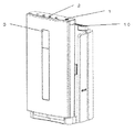
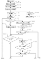
図1〜図9は本発明の実施の形態を示す加湿機能付き機空気清浄機を示すもので、図1はその外観図、図2はその空気清浄機の断面図、図3はその基本制御を示すブロック図、図4は送風ファン回転数と消費電力の関係を示すグラフ、図5は加湿量と消費電力の関係を示すグラフ、図6はその自動空気清浄運転および自動加湿運転における送風ランクの設定値および制御テーブル説明図、図7はその送風ランクと各性能の一例を示す表、図8はその自動運転制御の一例を示すフローチャート(その1)、図9は同じくその自動運転制御動作の一例を示すフローチャート(その2)である。
Hereinafter, embodiments of the present invention will be described with reference to the drawings.
1 to 9 show an air cleaner with a humidifying function according to an embodiment of the present invention. FIG. 1 is an external view thereof, FIG. 2 is a sectional view of the air cleaner, and FIG. 3 is a basic control thereof. FIG. 4 is a graph showing the relationship between the rotational speed of the blower fan and power consumption, FIG. 5 is a graph showing the relationship between the humidification amount and power consumption, and FIG. 6 is the blower rank in the automatic air cleaning operation and the automatic humidification operation. FIG. 7 is a table showing an example of the blower rank and each performance, FIG. 8 is a flowchart showing an example of the automatic operation control (part 1), and FIG. 9 is the automatic operation control operation. It is a flowchart (the 2) which shows an example.
図1、2に示すように本発明の実施の形態における家庭用加湿機能付き空気清浄機は、空気の粉塵を除去する集塵フィルター6とにおい成分を除去する脱臭フィルター5と、加湿するための加湿フィルター9と、加湿フィルターに給水するための給水タンク15とを備えており、かつ、集塵フィルター6、脱臭フィルター5、加湿フィルター9へ室内空気を通風させるための送風ファン7を備えている。
As shown in FIGS. 1 and 2, an air cleaner with a humidifying function for home use in an embodiment of the present invention includes a dust collection filter 6 that removes air dust, a
家庭用加湿機能付き空気清浄機は、その本体Aの背面側に室内空気の吸込口4を備え、吸込口の内側に脱臭フィルター5と集塵フィルター6を連続して備え、フィルターの下流側で風路を2つに分岐し、フィルターを通過して清浄された空気の一方は送風ファン7を通過して本体Aの上面に形成した吹出口10へ導かれ、他方は、本体の下方に設けられた加湿フィルター9を通過し後に送風ファン7を通過し、本体Aの上面に形成した吹出口10へと導かれる。
The air purifier with a humidifying function for home use has a
実施の形態における送風ファン7は、両吸込みのシロッコファンを用いることで、前述の2系統の風路を1つのファンで送風している。また、加湿フィルター9は、回転式円盤(図示せず)とその円盤の回転駆動用モーター(図示せず)を用いて、給水トレイ(図示せず)の水を汲み上げて濡れた円盤と円盤の間に風を通すことで加湿する方式としているため、円盤の回転を停止すれば、風路の切り替えを行わずとも、加湿フィルター(回転式円盤)への通気をしたままでも、加湿を停止することができるため、加湿をするか否かは、円盤駆動用モーターの制御を行うことで、任意に制御することが可能である。
The
図3に空気清浄機の制御ブロック図を記す。図1の加湿機能付き空気清浄機においては、天面に操作装置1と第1の表示装置2を備え、操作および温度検出装置(図示せず)および湿度検出装置(図示せず)による検出値などにより、制御部(図示せず)によって運転動作を決定し、送風ファン7の駆動用モーター8、円盤駆動用モーターなどの基本構成部品の制御および、第1の表示装置2、第2の表示装置3などの制御も併せて行う。
FIG. 3 shows a control block diagram of the air purifier. In the air cleaner with a humidifying function of FIG. 1, the
図4に、送風ファン7の駆動用モーターとしてブラシレスDCモーターを用いた場合の、送風ファン回転数に対する加湿機能付き空気清浄機の消費電力を示す。消費電力は、送風ファン駆動用モーターの消費電力と、センサー類、電源基板、表示基板の消費電力とを加えた値である。
In FIG. 4, the power consumption of the air cleaner with a humidification function with respect to rotation speed of a ventilation fan at the time of using a brushless DC motor as a drive motor of the
また、一般的には、送風量は、送風ファン7の回転数におおよそ比例するため、図示の送風ファン回転数の値は、すなわち、送風量の大きさを示しており、また、集塵および脱臭などの空気清浄能力は、送風量におおよそ比例するため、消費電力をファン回転数で除した値(図4の左軸に表示)のグラフは、単位風量すなわち一定の空気清浄能力あたりの消費電力を示していることになる。
In general, since the air flow rate is approximately proportional to the rotation speed of the
送風ファン7駆動用モーターを有する家庭用の空気清浄機や加湿機能付き空気清浄機、または加湿機においては、消費電力を低く抑えるために、ACコンデンサモーターよりも、ブラシレスDCモーターを用いる場合が多い。図示のように、特に900r/m(毎分900回転)以上の高回転域においては、送風量あたりの消費電力の値が大きく、空気清浄能力に対する消費電力の効率が悪いことがわかる。また、500r/m以下の低回転域においても、わずかに効率が悪化しており、610r/m(毎分610回転)付近で、単位風量すなわち一定の空気清浄能力あたりの消費電力(図4の左軸表示)が最も低く、最も効率の良い空気清浄運転を行っていることがわかる。
In home air purifiers, air purifiers with a humidifying function, or humidifiers that have a
図5に、送風ファン駆動用モーターとしてブラシレスDCモーターを用いた場合の、加湿量に対する加湿機能付き空気清浄機の消費電力を示す。消費電力は、送風ファン駆動用モーターの消費電力と、センサー類、電源基板、表示基板の消費電力とを加えた値である。一般的には、加湿量は、送風ファン回転数とは比例せず、加湿フィルターの構造によって運転の最適値が異なる。消費電力を加湿量で除した値(図5の左軸に表示)のグラフは、単位加湿量あたりの消費電力を示している。図示のように、実施例の加湿方式においては、760r/m(毎分760回転)付近において、送風量あたりの消費電力の値が最も小さく、効率の良い加湿運転を行っていることがわかる。 FIG. 5 shows the power consumption of the air purifier with a humidifying function with respect to the humidifying amount when a brushless DC motor is used as the blower fan driving motor. The power consumption is a value obtained by adding the power consumption of the motor for driving the blower fan and the power consumption of the sensors, the power supply board, and the display board. In general, the amount of humidification is not proportional to the rotational speed of the blower fan, and the optimum value of operation varies depending on the structure of the humidification filter. The graph of the value obtained by dividing the power consumption by the humidification amount (displayed on the left axis in FIG. 5) indicates the power consumption per unit humidification amount. As shown in the figure, in the humidification system of the example, it can be seen that the power consumption per blown amount is the smallest and efficient humidification operation is performed in the vicinity of 760 r / m (760 revolutions per minute).
従来の自動運転の制御においては、低回転域から高回転域の間で、あらかじめ7段階程度の設定回転数を備え、空気の汚れや湿度に応じて、段階的に回転数を変化させていた。 In the conventional automatic operation control, a preset rotational speed of about 7 steps is provided in advance between a low rotational speed range and a high rotational speed range, and the rotational speed is changed stepwise according to air dirt and humidity. .
図10に、従来の一般的な自動運転における、空気の汚れの検知値と運転回転数の制御テーブルを示す。なお、ここでいう「自動運転」とは、室内空気の湿度や清浄度などを検出する検知手段の検知信号に基づき、マイクロコンピュータ等を含む制御部が送風ファンの駆動用モーターの回転数を制御することをいう。 FIG. 10 shows a control table of air contamination detection values and operation rotational speeds in a conventional general automatic operation. The term “automatic operation” as used herein refers to a control unit including a microcomputer or the like that controls the number of revolutions of the motor for driving the blower fan based on a detection signal from a detection means that detects the humidity or cleanliness of indoor air. To do.
従来は図10のように、送風ランク3から5の3段階を用いて、ほこりセンサーまたはにおいセンサーの検知値が高いと送風ファンの回転数を上げ、運転を続けて検知値が低くなるにつれ、徐々に回転数を下げる制御としている。 Conventionally, as shown in FIG. 10, using three stages of blower ranks 3 to 5, if the detection value of the dust sensor or odor sensor is high, the rotation speed of the blower fan is increased, and the detection value decreases as the operation continues. Control is performed to gradually reduce the rotational speed.
同じく図10に、従来の一般的な自動運転における、湿度の検知値と運転回転数の制御テーブルを示す。図10のように、検知湿度が設定湿度よりも低い場合は、比較的、回転数の高い、送風ランク5で運転し、設定湿度に到達後は、送風ファンを停止する制御としている。なお、仮にランク7の場合、その回転数1350r/mは送風ファンの定格最高速度であり、送風量は増えるが、運転音が大きくなるから、特に家庭用の空気清浄機や加湿器のように静かな部屋で使用する環境には騒音となって適さないから、このようなランク7は実際には使用されない。
Similarly, FIG. 10 shows a control table of the detected humidity value and the operating rotational speed in the conventional general automatic operation. As shown in FIG. 10, when the detected humidity is lower than the set humidity, the operation is performed at a relatively high rotation speed, the
次に、本発明における、消費電力を低く抑える効果を目的とした送風ファン駆動用モーターおよび本体の表示部の制御について説明する。 Next, control of the blower fan driving motor and the display unit of the main body for the purpose of suppressing power consumption in the present invention will be described.
図6に、本発明の実施の形態にける自動空気清浄運転および自動加湿運転における、送風ランクの設定値および制御テーブルを示す。 FIG. 6 shows the setting value and control table of the air blowing rank in the automatic air cleaning operation and the automatic humidification operation in the embodiment of the present invention.
図7に示すように、自動空気清浄運転においては、図4のグラフで示した、空気清浄時に最も効率のよい送風ファン回転数である610r/mを主に用いる運転とする。また、室内の空気が清浄となり、汚れを検知しなくなった後は、送風ファンを停止して、さらに消費電力を抑制する制御とする。 As shown in FIG. 7, in the automatic air cleaning operation, an operation mainly using 610 r / m, which is the most efficient blower fan rotation speed during air cleaning, shown in the graph of FIG. In addition, after the indoor air becomes clean and dirt is no longer detected, the blower fan is stopped and control is performed to further reduce power consumption.
同じく図7に、本は発明の実施の形態の自動加湿運転における、湿度の検知値と運転回転数の制御テーブルを示す。図4のグラフで示した、加湿時に最も効率のよい送風ファン回転数である760r/mを主に用いる制御とすることで、消費電力を抑制する。また、設定湿度に到達後に、送風ファンを停止する点は、従来例と同様である。 Similarly, FIG. 7 shows a control table of humidity detection values and operation rotational speeds in the automatic humidification operation according to the embodiment of the present invention. The power consumption is suppressed by using the control mainly using 760 r / m, which is the most efficient blower fan rotation speed during humidification, as shown in the graph of FIG. Moreover, the point which stops a ventilation fan after reaching setting humidity is the same as that of a prior art example.
また、実施の形態おいては、該自動運転モードを選択時には、汚れ表示部および湿度表示部のLEDの輝度を下げる制御とすることで、さらに消費電力を削減する。 In the embodiment, when the automatic operation mode is selected, the power consumption is further reduced by controlling the brightness of the LEDs of the dirt display unit and the humidity display unit.
図7に、各送風ランクにおける、消費電力やその他の特性値を示す。図7より、自動空
気清浄運転の「汚れ大」において、従来の送風ランク5(910r/m)から実施例の送風ランク3(610r/m)に変更することで、約58%の消費電力を削減することができる(4.0W÷9.5W)。
FIG. 7 shows power consumption and other characteristic values in each blower rank. As shown in FIG. 7, in the “large dirt” in the automatic air cleaning operation, by changing from the conventional blower rank 5 (910 r / m 2 ) to the blower rank 3 (610 r / m 2 ) of the example, consumption of about 58% Electric power can be reduced (4.0 W / 9.5 W).
また、風量低下により、空気清浄能力は、約33%(610r/m÷910r/mで約66%の能力になるから)悪化するが、一定の汚れを除去するための消費電力量は、従来の制御に比べ、約37%削減できることがわかる。
In addition, the air cleaning capacity deteriorates by about 33% (because it becomes about 66% capacity at 610 r / m ÷ 910 r / m ) due to the decrease in the air volume, but the power consumption for removing certain dirt is It can be seen that it can be reduced by about 37% compared to the conventional control.
また、加湿量においては、従来の送風ランク5から実施例の送風ランク4に変更することで、約31%(12.5W÷18W)の消費電力を削減することができる。また、風量低下により、加湿能力は、約14%(加湿量350mlが300mlに)悪化するが、一定の加湿量を得るための消費電力は、従来の制御に比べ、約19%削減できることがわかる。
Further, in terms of the humidification amount, the power consumption can be reduced by about 31% (12.5 W ÷ 18 W) by changing from the
図8と図9に、本発明の実施の形態における自動空気清浄運転と自動加湿運転を組み合わせた場合の、動作フローチャートを示す。 FIG. 8 and FIG. 9 show operation flowcharts when the automatic air cleaning operation and the automatic humidification operation in the embodiment of the present invention are combined.
制御部14は、操作装置1にて運転スイッチのオン信号を入力すると(S11)、図3に示すほこりセンサー11、においセンサー12及び湿度センサー13の各センサーの検知値を読み込む(S12〜14)。なお、ここでほこりセンサー11に取り込まれた情報に基づき制御部14は後述するほこりモニタの点灯数を決定する。
When the controller 14 receives an operation switch ON signal from the operation device 1 (S11), the control unit 14 reads detection values of the dust sensor 11, the odor sensor 12, and the
次に、選択された運転モードに応じて運転を開始する。実施例の制御を行う省エネ運転(S15)が選択されると、表示部のLEDの輝度を下げるとともに(S16)、自動運転を開始する。省エネ運転が選択されなかった場合は(S17)、各々に設定された制御へ移行する(S18)。 Next, the operation is started according to the selected operation mode. When the energy saving operation (S15) for controlling the embodiment is selected, the brightness of the LED of the display unit is lowered (S16), and the automatic operation is started. When the energy saving operation is not selected (S17), the process proceeds to the control set for each (S18).
省エネ運転(S15)は、表示部の輝度を下げる(S16)と同時に、湿度センサー(13)の検知値による判定を行う。検知値が目標湿度50%以下の場合は、送風ランク4で送風するとともに、加湿ディスクを回転し、加湿運転を開始する(S20)。検知値が50%を超えると、加湿ディスクの回転を停止し、次に、ほこりモニタの点灯数を決定する情報から点灯数を判定する。言い換えると、前記ステップS13で入手したほこりセンサーの情報(検出値)でほこりモニタの点灯数が決められるが、ステップS24ではその点灯数を決定する信号から点灯数を判定する。
In the energy saving operation (S15), the brightness of the display unit is lowered (S16), and at the same time, the determination based on the detection value of the humidity sensor (13) is performed. When the detected value is 50% or less of the target humidity, the air is blown at the
ここで、ほこりモニタは、多段階、例えば、9個のLEDによる9段階の表示幅を備えており、ほこりセンサーの検出値すなわち検知したほこりの量に応じて、9個のLEDを段階的に点灯させる制御としている。ほこりが多ければ点灯数を増やし、ほこりが減るにつれ、点灯数を減らす。ほこりモニタの点灯数が3個以上ならば(S24)、送風ランク3で運転を行う。
Here, the dust monitor has a multi-stage display width of nine stages, for example, nine LEDs, and the nine LEDs are stepped in accordance with the detection value of the dust sensor, that is, the detected amount of dust. It is controlled to light up. If there is a lot of dust, increase the number of lights, and decrease the number of lights as the dust decreases. If the number of lighting of the dust monitor is 3 or more (S24), the operation is performed at the
運転によって室内のほこりが減り、ほこりモニタの点灯数が3個未満となると、次に、においモニタの点灯数を判定する。ここで、においモニタは、多段階、例えば、3個のLEDによる3段階の表示幅を備えており、においセンサーの検出値すなわち検知したにおいの強さに応じて、3個のLEDを段階的に点灯させる制御としている。においが強ければ点灯数を増やし、においが減るにつれ、点灯数を減らす。においモニタの点灯数が2個以上ならば(S28)、送風ランク3で継続して運転を行う。
If the indoor dust is reduced by driving and the number of lights on the dust monitor is less than 3, then the number of lights on the odor monitor is determined. Here, the odor monitor has a multi-stage display width of three stages, for example, three LEDs, and the three LEDs are stepped according to the detected value of the odor sensor, that is, the detected odor intensity. It is set to control to light up. If the smell is strong, increase the number of lights, and as the smell decreases, decrease the number of lights. If the number of lighting of the odor monitor is 2 or more (S28), the operation is continuously performed at the
以上の判定および制御を繰り返し、湿度が50%を下回り、ほこりセンサー11およびにおいセンサー12の検知値が下がれば、送風ファン7の回転を停止し、室内の空気が変化して、再び、湿度の上昇または、ほこり、においなどの汚れを検知すると、送風を開始する。
When the above determination and control are repeated and the humidity falls below 50% and the detection values of the dust sensor 11 and the odor sensor 12 decrease, the rotation of the
さらに、上記の実施の形態の制御に加え、また、該自動運転を選択時に、空気の汚れが所定の値を下回るか、または湿度が所定の値を超えたときには、汚れまたは湿度を検知する検知手段の通電を間欠的に停止する制御を行っても良い。例えば、送風ファン7の停止中に、各センサー11,12、13の全てあるいはいずれかの通電を、3分間の通電と7分間の通電停止を繰り返すことで、さらに消費電力量を削減することができる。
Further, in addition to the control of the above-described embodiment, and when the automatic operation is selected, when the air dirt is lower than a predetermined value or the humidity exceeds a predetermined value, detection for detecting the dirt or humidity is detected. You may perform control which stops electricity supply of a means intermittently. For example, the power consumption can be further reduced by repeating energization of all or any of the
本発明は、上記の実施の形態に制限されるものではなく、例えば制御テーブルは単一でなく、複数を備え、室温や運転時間に応じて制御を変化させ、より省エネを優先したり、あるいは、空気清浄性能や加湿性能を優先したものとの中間性能を得られる制御としてもよい。 The present invention is not limited to the above-described embodiment. For example, the control table is not single, and a plurality of control tables are provided, and control is changed according to room temperature and operation time, and energy saving is prioritized, or Further, it may be a control capable of obtaining an intermediate performance with a priority on air cleaning performance and humidification performance.
また、自動運転時の汚れの検知値と汚れ表示の相関や、目標湿度の値は、他の値としたり、使用者が任意に設定できる方式としてもよい。 Further, the correlation between the detected value of dirt and the display of dirt during automatic operation, and the target humidity value may be other values, or a method that can be arbitrarily set by the user.
また、省エネ運転選択時は、2つの表示装置2,3を全てを消灯してもよいし、不要な表示のみ消灯してもよい。
When the energy saving operation is selected, all of the two
また、空気清浄の方式は、集塵フィルターおよび脱臭フィルターを用いた方式に限らず、高圧電極を用いた電気集塵方式や、触媒を用いて臭気を分解する方式としてもよく、本発明は集塵方式の違いには何ら関係なく実施可能である。 The air cleaning method is not limited to a method using a dust collection filter and a deodorization filter, and may be an electric dust collection method using a high voltage electrode, or a method for decomposing odor using a catalyst. It can be implemented regardless of the difference in the dust system.
また、本発明の送風ファン7駆動用モーターの制御方法は、加湿機能付き空気清浄機に限るものではなく、空気清浄機や加湿機、除湿機など、他の空気処理機器に用いてもよい。
In addition, the method for controlling the motor for driving the
本発明の送風ファン駆動用モーターと表示部の制御装置は、室内の除塵または脱臭、加湿を行いながら、消費電力量を抑制する運転に利用することができる空気処理機器に広く利用できる。 INDUSTRIAL APPLICABILITY The blower fan driving motor and the display unit control device of the present invention can be widely used for air treatment equipment that can be used for operation that reduces power consumption while performing indoor dust removal, deodorization, and humidification.
1 操作装置、2 第1の表示装置、3 第2の表示装置、4 吸込口、5 脱臭フィルター、6 集塵フィルター、7 送風ファン、8 送風ファン駆動用モーター、9 加湿フィルター、10 吹出口、11 ほこりセンサー、12 においセンサー、
13 湿度センサー、14 制御部、15 給水タンク。
DESCRIPTION OF
13 Humidity sensor, 14 Control unit, 15 Water supply tank.
Claims (7)
送風ファンと、
送風ファン駆動用モーターと、
空気の汚れまたは湿度を検知する検知手段と、
空気の状態に応じて自動で送風ファン回転数を決定する制御部とを備えた空気処理機器において、
前記制御部は、前記検知手段の検知信号に基づき前記制御部が前記モーターの回転数を制御する自動運転時において、ファン回転数あたりのモーターの消費電力が低い回転数域を使用することを特徴とする空気処理機器の制御装置。 An indoor air inlet and a treated air outlet;
A blower fan,
A fan driving motor,
Detection means for detecting air dirt or humidity;
In an air treatment device equipped with a control unit that automatically determines the number of fan rotations according to the state of air,
The control unit uses a rotation speed range in which power consumption of the motor per fan rotation speed is low during automatic operation in which the control section controls the rotation speed of the motor based on a detection signal of the detection means. Control device for air treatment equipment.
送風ファンと、
送風ファン駆動用モーターと、
空気の汚れまたは湿度を検知する検知手段と、
運転状態または空気の状態のいずれかあるいは両方を表示する表示部と、
前記モーターと表示部への通電を制御する制御部とを備えた空気処理機器において、
前記制御部は、前記検知手段の検知信号に基づき前記制御部が前記モーターの回転数を制御する自動運転時において、ファン回転数あたりのモーターの消費電力が低い回転数域を使用するとともに、あらかじめ設定された運転モードを選択したときに、前記表示部の消費電力を下げるため、その表示用電力の供給を制限又は停止することを特徴とする空気処理機器の制御装置。 An indoor air inlet and a treated air outlet;
A blower fan,
A fan driving motor,
Detection means for detecting air dirt or humidity;
A display for displaying either or both of the operating state and the air state;
In an air treatment device including the motor and a control unit that controls energization to the display unit,
In the automatic operation in which the control unit controls the rotation speed of the motor based on the detection signal of the detection means, the control unit uses a rotation speed range where the power consumption of the motor per fan rotation speed is low, and in advance When the set operation mode is selected, in order to reduce the power consumption of the display unit, the supply of the display power is limited or stopped.
送風ファンと、
送風ファン駆動用モーターと、
空気の状態を検知する検知手段と、
空気の状態に応じて自動で送風ファン回転数を決定する制御部と、
運転状態または空気の状態のいずれかあるいは両方を表示する表示部を備えた空気処理機器において、
前記制御部は、前記検知手段の検知信号に基づき前記制御部が前記モーターの回転数を制御する自動運転時において、ファン回転数あたりのモーターの消費電力が低い回転数を使用するとともに、前記表示部の消費電力を下げるため、その表示用電力の供給を制限又は停止することを特徴とする空気処理機器の制御装置。 An indoor air inlet and a treated air outlet;
A blower fan,
A fan driving motor,
Detection means for detecting the state of air;
A control unit that automatically determines the rotational speed of the blower fan according to the air state;
In an air treatment device having a display unit that displays either or both of the operating state and the air state,
In the automatic operation in which the control unit controls the number of rotations of the motor based on the detection signal of the detection unit, the control unit uses the number of rotations with low power consumption of the motor per number of fan rotations, and the display to reduce the power consumption of the parts, air processing control unit of the device you and limits or stops the supply of the display power.
送風ファンと、
送風ファン駆動用モーターと、
空気の汚れまたは湿度を検知する検知手段と、
運転状態または空気の状態のいずれかあるいは両方を表示する表示部と、
空気の状態に応じて自動で送風ファン回転数を決定するとともに前記モーターと表示部への通電を制御する制御部とを備えた空気処理機器において、
前記制御部は、前記検知手段の検知信号に基づき前記制御部が前記モーターの回転数を制御する自動運転時において、ファン回転数あたりのモーターの消費電力が低い回転数を使用するとともに、空気の状態があらかじめ設定した状態になった後に、送風ファンを一度停止するとともに、前記表示部の消費電力を下げるため、その表示用電力の供給を制限又は停止することを特徴とする空気処理機器の制御装置。 An indoor air inlet and a treated air outlet;
A blower fan,
A fan driving motor,
Detection means for detecting air dirt or humidity;
A display for displaying either or both of the operating state and the air state;
In an air treatment apparatus comprising a control unit that automatically determines the number of fan rotations according to the state of air and controls the energization of the motor and the display unit,
In the automatic operation in which the control unit controls the number of rotations of the motor based on the detection signal of the detection unit, the control unit uses the number of rotations with low power consumption of the motor per number of rotations of the fan . After the state becomes a preset state, the blower fan is stopped once and the supply of display power is limited or stopped in order to reduce the power consumption of the display unit. apparatus.
送風ファンと、
送風ファン駆動用モーターと、
空気の汚れまたは湿度を検知する検知手段と、
空気の状態に応じて自動で送風ファン回転数を決定する制御部と、
運転状態または空気の状態のいずれかあるいは両方を表示する表示部を備えた空気処理機器において、
前記制御部は、前記検知手段の検知信号に基づき前記制御部が前記モーターの回転数を制御する自動運転時において、ファン回転数あたりのモーターの消費電力が低い回転数を使用するとともに、空気の状態があらかじめ設定された状態になった後に、送風ファンを一度停止するとともに、前記検知手段の動作を間欠運転に切り替え、検知手段が検知した値に応じて送風ファンの運転を制御することを特徴とする空気処理機器の制御装置。 An indoor air inlet and a treated air outlet;
A blower fan,
A fan driving motor,
Detection means for detecting air dirt or humidity;
A control unit that automatically determines the rotational speed of the blower fan according to the air state;
In an air treatment device having a display unit that displays either or both of the operating state and the air state,
In the automatic operation in which the control unit controls the number of rotations of the motor based on the detection signal of the detection unit, the control unit uses the number of rotations with low power consumption of the motor per number of rotations of the fan . After the state becomes a preset state, the blower fan is stopped once, the operation of the detection means is switched to intermittent operation, and the operation of the blower fan is controlled according to the value detected by the detection means. Control device for air treatment equipment.
Priority Applications (1)
| Application Number | Priority Date | Filing Date | Title |
|---|---|---|---|
| JP2008200483A JP5083102B2 (en) | 2008-08-04 | 2008-08-04 | Control device for air treatment equipment |
Applications Claiming Priority (1)
| Application Number | Priority Date | Filing Date | Title |
|---|---|---|---|
| JP2008200483A JP5083102B2 (en) | 2008-08-04 | 2008-08-04 | Control device for air treatment equipment |
Publications (3)
| Publication Number | Publication Date |
|---|---|
| JP2010038414A JP2010038414A (en) | 2010-02-18 |
| JP2010038414A5 JP2010038414A5 (en) | 2010-10-07 |
| JP5083102B2 true JP5083102B2 (en) | 2012-11-28 |
Family
ID=42011168
Family Applications (1)
| Application Number | Title | Priority Date | Filing Date |
|---|---|---|---|
| JP2008200483A Expired - Fee Related JP5083102B2 (en) | 2008-08-04 | 2008-08-04 | Control device for air treatment equipment |
Country Status (1)
| Country | Link |
|---|---|
| JP (1) | JP5083102B2 (en) |
Families Citing this family (6)
| Publication number | Priority date | Publication date | Assignee | Title |
|---|---|---|---|---|
| JP5724967B2 (en) * | 2012-08-09 | 2015-05-27 | ダイキン工業株式会社 | Humidifier |
| JP5772877B2 (en) * | 2013-05-28 | 2015-09-02 | ダイキン工業株式会社 | Air purifier with dehumidifying function |
| JP6161444B2 (en) * | 2013-07-16 | 2017-07-12 | ダイキン工業株式会社 | Air conditioner |
| JP6350344B2 (en) * | 2015-03-10 | 2018-07-04 | 三菱電機株式会社 | Air cleaner |
| CN109668261B (en) * | 2018-12-24 | 2020-09-25 | 广东美的制冷设备有限公司 | Control method and device for air conditioning device and air conditioning device |
| EP4340034A1 (en) * | 2022-09-15 | 2024-03-20 | Nexperia B.V. | Mps diode having a non-uniformly doped region and method for manufacturing the same |
Family Cites Families (10)
| Publication number | Priority date | Publication date | Assignee | Title |
|---|---|---|---|---|
| JPS6325446A (en) * | 1986-07-18 | 1988-02-02 | Nippon Telegr & Teleph Corp <Ntt> | Control of air-conditioning machine |
| JPH105519A (en) * | 1996-06-26 | 1998-01-13 | Daikin Ind Ltd | Air purifier with air status display function |
| JPH11304285A (en) * | 1998-04-17 | 1999-11-05 | Hitachi Ltd | Air conditioner |
| JP2000046384A (en) * | 1998-07-29 | 2000-02-18 | Hitachi Hometec Ltd | humidifier |
| JP2001193694A (en) * | 2000-01-14 | 2001-07-17 | Denso Corp | Air blower |
| JP4182662B2 (en) * | 2001-12-19 | 2008-11-19 | ダイキン工業株式会社 | Air conditioner |
| JP2006162125A (en) * | 2004-12-06 | 2006-06-22 | Matsushita Electric Ind Co Ltd | Air conditioner display device |
| JP2007107778A (en) * | 2005-10-12 | 2007-04-26 | Matsushita Electric Ind Co Ltd | Ventilation equipment |
| JP4519815B2 (en) * | 2006-08-07 | 2010-08-04 | 三菱電機株式会社 | Air purifier with humidification function |
| JP2008145047A (en) * | 2006-12-11 | 2008-06-26 | Sharp Corp | Humidifier |
-
2008
- 2008-08-04 JP JP2008200483A patent/JP5083102B2/en not_active Expired - Fee Related
Also Published As
| Publication number | Publication date |
|---|---|
| JP2010038414A (en) | 2010-02-18 |
Similar Documents
| Publication | Publication Date | Title |
|---|---|---|
| JP5083102B2 (en) | Control device for air treatment equipment | |
| JP2019045143A (en) | Air conditioner | |
| JP6591936B2 (en) | Humidifier | |
| JP6925293B2 (en) | Humidified air purifier | |
| JP2013072584A (en) | Air purifier | |
| TW201837388A (en) | Air-cleaning device | |
| JP2009236373A (en) | Integrated air conditioner | |
| JP5053208B2 (en) | Air cleaner | |
| CN103574840B (en) | With the air cleaner of humidification function | |
| JP4519815B2 (en) | Air purifier with humidification function | |
| KR102426199B1 (en) | Air conditioner and the control method thereof | |
| CN103574813B (en) | Damping device | |
| JP5593959B2 (en) | Control device for air treatment equipment | |
| CN108027160A (en) | Air conditioner | |
| JP6727869B2 (en) | Humidity control device | |
| KR102334247B1 (en) | Sleeping mode controlling apparatus for humidification air purifier | |
| JP2014217810A (en) | Mist generating device | |
| JP2013070791A (en) | Air purifier | |
| JP2013015302A (en) | Air cleaner | |
| JP5003162B2 (en) | Air conditioner | |
| JP5900234B2 (en) | Humidifier | |
| JP6090231B2 (en) | Air purifier | |
| JP2019152365A (en) | Humidifier | |
| KR100789711B1 (en) | Control method of air cleaner | |
| KR100464513B1 (en) | Air cleaner and operation control method thereof |
Legal Events
| Date | Code | Title | Description |
|---|---|---|---|
| A521 | Request for written amendment filed |
Free format text: JAPANESE INTERMEDIATE CODE: A523 Effective date: 20100824 |
|
| A621 | Written request for application examination |
Free format text: JAPANESE INTERMEDIATE CODE: A621 Effective date: 20100824 |
|
| A977 | Report on retrieval |
Free format text: JAPANESE INTERMEDIATE CODE: A971007 Effective date: 20120209 |
|
| A131 | Notification of reasons for refusal |
Free format text: JAPANESE INTERMEDIATE CODE: A131 Effective date: 20120214 |
|
| A521 | Request for written amendment filed |
Free format text: JAPANESE INTERMEDIATE CODE: A523 Effective date: 20120315 |
|
| TRDD | Decision of grant or rejection written | ||
| A01 | Written decision to grant a patent or to grant a registration (utility model) |
Free format text: JAPANESE INTERMEDIATE CODE: A01 Effective date: 20120807 |
|
| A01 | Written decision to grant a patent or to grant a registration (utility model) |
Free format text: JAPANESE INTERMEDIATE CODE: A01 |
|
| A61 | First payment of annual fees (during grant procedure) |
Free format text: JAPANESE INTERMEDIATE CODE: A61 Effective date: 20120820 |
|
| R150 | Certificate of patent or registration of utility model |
Ref document number: 5083102 Country of ref document: JP Free format text: JAPANESE INTERMEDIATE CODE: R150 Free format text: JAPANESE INTERMEDIATE CODE: R150 |
|
| FPAY | Renewal fee payment (event date is renewal date of database) |
Free format text: PAYMENT UNTIL: 20150914 Year of fee payment: 3 |
|
| R250 | Receipt of annual fees |
Free format text: JAPANESE INTERMEDIATE CODE: R250 |
|
| R250 | Receipt of annual fees |
Free format text: JAPANESE INTERMEDIATE CODE: R250 |
|
| R250 | Receipt of annual fees |
Free format text: JAPANESE INTERMEDIATE CODE: R250 |
|
| R250 | Receipt of annual fees |
Free format text: JAPANESE INTERMEDIATE CODE: R250 |
|
| R250 | Receipt of annual fees |
Free format text: JAPANESE INTERMEDIATE CODE: R250 |
|
| R250 | Receipt of annual fees |
Free format text: JAPANESE INTERMEDIATE CODE: R250 |
|
| R250 | Receipt of annual fees |
Free format text: JAPANESE INTERMEDIATE CODE: R250 |
|
| R250 | Receipt of annual fees |
Free format text: JAPANESE INTERMEDIATE CODE: R250 |
|
| LAPS | Cancellation because of no payment of annual fees |