JP5083000B2 - Electronic component device and method of manufacturing electronic component device - Google Patents
Electronic component device and method of manufacturing electronic component device Download PDFInfo
- Publication number
- JP5083000B2 JP5083000B2 JP2008099753A JP2008099753A JP5083000B2 JP 5083000 B2 JP5083000 B2 JP 5083000B2 JP 2008099753 A JP2008099753 A JP 2008099753A JP 2008099753 A JP2008099753 A JP 2008099753A JP 5083000 B2 JP5083000 B2 JP 5083000B2
- Authority
- JP
- Japan
- Prior art keywords
- electrode
- electronic component
- metal part
- metal
- tin
- Prior art date
- Legal status (The legal status is an assumption and is not a legal conclusion. Google has not performed a legal analysis and makes no representation as to the accuracy of the status listed.)
- Expired - Fee Related
Links
Images
Classifications
-
- H—ELECTRICITY
- H01—ELECTRIC ELEMENTS
- H01L—SEMICONDUCTOR DEVICES NOT COVERED BY CLASS H10
- H01L2224/00—Indexing scheme for arrangements for connecting or disconnecting semiconductor or solid-state bodies and methods related thereto as covered by H01L24/00
- H01L2224/01—Means for bonding being attached to, or being formed on, the surface to be connected, e.g. chip-to-package, die-attach, "first-level" interconnects; Manufacturing methods related thereto
- H01L2224/10—Bump connectors; Manufacturing methods related thereto
- H01L2224/15—Structure, shape, material or disposition of the bump connectors after the connecting process
- H01L2224/16—Structure, shape, material or disposition of the bump connectors after the connecting process of an individual bump connector
- H01L2224/161—Disposition
- H01L2224/16151—Disposition the bump connector connecting between a semiconductor or solid-state body and an item not being a semiconductor or solid-state body, e.g. chip-to-substrate, chip-to-passive
- H01L2224/16221—Disposition the bump connector connecting between a semiconductor or solid-state body and an item not being a semiconductor or solid-state body, e.g. chip-to-substrate, chip-to-passive the body and the item being stacked
- H01L2224/16225—Disposition the bump connector connecting between a semiconductor or solid-state body and an item not being a semiconductor or solid-state body, e.g. chip-to-substrate, chip-to-passive the body and the item being stacked the item being non-metallic, e.g. insulating substrate with or without metallisation
-
- H—ELECTRICITY
- H01—ELECTRIC ELEMENTS
- H01L—SEMICONDUCTOR DEVICES NOT COVERED BY CLASS H10
- H01L2224/00—Indexing scheme for arrangements for connecting or disconnecting semiconductor or solid-state bodies and methods related thereto as covered by H01L24/00
- H01L2224/80—Methods for connecting semiconductor or other solid state bodies using means for bonding being attached to, or being formed on, the surface to be connected
- H01L2224/81—Methods for connecting semiconductor or other solid state bodies using means for bonding being attached to, or being formed on, the surface to be connected using a bump connector
- H01L2224/8138—Bonding interfaces outside the semiconductor or solid-state body
- H01L2224/81385—Shape, e.g. interlocking features
Landscapes
- Wire Bonding (AREA)
Description
本発明は、電子部品装置及び電子部品装置の製造方法に関し、より具体的には、例えばエリアアレイ型と呼ばれるBGA(Ball Grid Array)又はCSP(Chip Size Package)等のパッケージ型半導体装置が配線回路基板に実装されてなる電子部品装置、及び当該電子部品装置の製造方法に関する。 The present invention relates to an electronic component device and a method for manufacturing the electronic component device. More specifically, for example, a package type semiconductor device such as a BGA (Ball Grid Array) or CSP (Chip Size Package) called an area array type is used as a wiring circuit. The present invention relates to an electronic component device mounted on a substrate and a method for manufacturing the electronic component device.
近年の電子機器の小型化・高密度化・高機能化に伴い、電子部品の小型化・薄型化が要求されている。そこで、半導体装置として、小型化により実装面積を低減させた高密度実装に優れ、高機能化に伴う入出力ピン数の増加に対応可能なパッケージとして、ボール・グリッド・アレイ(BGA:Ball Grid Array)又はCSP(Chip Size Package)等の表面実装型パッケージが提案されている。 With recent miniaturization, high density, and high functionality of electronic devices, there is a demand for miniaturization and thinning of electronic components. Therefore, a ball grid array (BGA: Ball Grid Array) is available as a semiconductor device that is excellent in high-density mounting with a reduced mounting area due to miniaturization and that can handle an increase in the number of input / output pins accompanying higher functionality. ) Or surface mount packages such as CSP (Chip Size Package) have been proposed.
BGA型半導体装置においては、上面に半導体素子が載置・固着された支持基板(パッケージ基板)の下面に、所謂半田バンプと称される球状の外部接続用突起電極が複数グリッド状に配設されている。支持基板は、配線回路基板(マザーボード)上に半田バンプを介して搭載され、支持基板の電極は、半田バンプを介して配線回路基板の配線部に接続される。 In a BGA type semiconductor device, spherical external connection protruding electrodes called so-called solder bumps are arranged in a plurality of grids on the lower surface of a support substrate (package substrate) on which a semiconductor element is mounted and fixed on the upper surface. ing. The support substrate is mounted on the printed circuit board (motherboard) via solder bumps, and the electrodes of the support substrate are connected to the wiring portion of the printed circuit board via the solder bumps.
BGA型半導体装置は、図1に示す方法により、配線回路基板に実装される。 The BGA type semiconductor device is mounted on a printed circuit board by the method shown in FIG.
図1(a)に示すように、先ず、ガラスエポキシ樹脂等の絶縁性樹脂を基材とし、その表面に銅(Cu)等からなる導電層が選択的に配設された配線用基板を複数積層して形成された支持基板(パッケージ基板)10が用意される。 As shown in FIG. 1A, first, a plurality of wiring boards having an insulating resin such as a glass epoxy resin as a base material and a conductive layer made of copper (Cu) or the like selectively disposed on the surface thereof are provided. A support substrate (package substrate) 10 formed by stacking is prepared.
支持基板10において、図示を省略する半導体素子が実装される主面と反対側の主面上には、銅(Cu)を主成分とする銅(Cu)層部がフォトリソグラフィー法等により形成され、当該銅(Cu)層部上には、例えばニッケル(Ni)を主成分とするニッケル(Ni)層及び金(Au)を主成分とする金(Au)層部がこの順にめっき法により積層されて、これにより電極部2が形成されている。なお、支持基板10の当該主面であって、電極部2が形成されていない箇所には、ポリイミド等の絶縁膜3が形成されている。
In the support substrate 10, a copper (Cu) layer portion containing copper (Cu) as a main component is formed by a photolithography method or the like on the main surface opposite to the main surface on which a semiconductor element (not shown) is mounted. On the copper (Cu) layer portion, for example, a nickel (Ni) layer mainly composed of nickel (Ni) and a gold (Au) layer portion mainly composed of gold (Au) are laminated in this order by a plating method. Thus, the
電極部2上には、錫(Sn)及び鉛(Pb)が例えば約6対4の割合で構成された共晶半田から成る球状の外部接続用突起電極たる半田バンプ4が形成されている。錫(Sn)及び鉛(Pb)から構成された共晶半田は、温度変化に伴う伸びが大きく、また、疲労寿命特性に優れる。なお、支持基板10と後述する配線回路基板(マザーボード)20とが半田バンプ4を介して接合されるまで、半田バンプ4の融点以上の温度、例えば200℃以上の温度でのリフロー加熱処理が、施される。
On the
なお、電極部2を構成するニッケル(Ni)層と半田バンプ4の接合界面には、錫(Sn)−ニッケル(Ni)から成るバリア層6が形成されている。
A barrier layer 6 made of tin (Sn) -nickel (Ni) is formed at the bonding interface between the nickel (Ni) layer constituting the
一方、ガラスエポキシ樹脂等の絶縁性樹脂を基材とし、その表面に銅(Cu)等からなる導電層が選択的に配設された配線回路基板20が、支持基板10の下方に用意される。
On the other hand, a printed
配線回路基板20の主面であって、支持基板10に対向している面上には、銅(Cu)から成る電極21が形成されている。また、配線回路基板20の当該主面であって、電極21が形成されていない箇所には、ソルダーレジスト膜22が形成されている。
An
そして、支持基板10に接合された半田バンプ4と、配線回路基板20の主面上に形成された電極21とを位置合わせした後に、図1(b)に示すように、配線回路基板20の電極21に、支持基板10に接合された半田バンプ4が接合される。
Then, after aligning the
このようにして、半田バンプ4を介して回路配線基板20に電気的に接続された半導体パッケージは、リードを介して回路配線基板20に接合される場合に比し、リードの配線長を短くできるため、高速電気特性に優れる。
In this manner, the semiconductor package electrically connected to the
また、半田バンプ4の径が小さいほど、半田バンプ4のピッチを微細にすることができり、例えば、半田バンプ4の径が600乃至750μmの場合、半田バンプ4のピッチを1乃至1.5mm程度にできる。即ち、半田バンプ4は支持基板10の下面全面に亘り多数形成することができるため、多ピン構造とするのに好適である。
Further, the smaller the diameter of the
ところで、近年、環境保全の観点から、半田バンプとして、鉛(Pb)成分を含まない所謂鉛(Pb)フリー半田として、錫(Sn)を主成分とした半田材料、例えば、錫(Sn)−銀(Ag)−銅(Cu)等から成る半田材料の使用が進められてきている。 By the way, in recent years, from the viewpoint of environmental protection, as a solder bump, a so-called lead (Pb) -free solder not containing a lead (Pb) component, a solder material mainly composed of tin (Sn), for example, tin (Sn) − A solder material made of silver (Ag) -copper (Cu) or the like has been used.
なお、その他、半導体チップと、リードフレームの一部であるリード部およびタブ部と、前記半導体チップと前記タブ部を接続するダイボンド半田接続部と、前記半導体チップを封止する樹脂封止部を有する半導体装置であって、前記ダイボンド半田接続部は、鉛(Pb)フリーのベース半田と鉛(Pb)フリーの金属を有し、前記ベース半田は錫(Sn)単体若しくは錫(Sn)を主成分とする化合物であり、前記鉛(Pb)フリー金属は260℃において溶融しない金属であり、さらに前記鉛(Pb)フリー金属同士は金属結合せず、前記ベース半田内で前記鉛(Pb)フリー金属が浮島状に分布している半導体装置が提案されている。(特許文献1参照)
また、基板上に多数の島状半田ペースト領域を形成し、各島状半田ペースト領域に金属ボールを配置し、その後基板上の半田を溶融させる半田ボールの製造方法が提案されている。(特許文献2参照)
更に、錫(Sn)を主成分とする2種類以上の合金粉末をフラックスと混合して、全体として所望の重量比になるように構成し、銅(Cu)ランドと電子部品間で半田の組成を傾斜分布させ、銅(Cu)ランドに対しては濡れ性を向上させ、電子部品に対しては半田付け強度を向上させたことを特徴とするクリーム半田も提案されている。(特許文献3参照)
In addition, a solder ball manufacturing method has been proposed in which a number of island-shaped solder paste regions are formed on a substrate, metal balls are disposed in each of the island-shaped solder paste regions, and then the solder on the substrate is melted. (See Patent Document 2)
Further, two or more kinds of alloy powders mainly composed of tin (Sn) are mixed with a flux so as to have a desired weight ratio as a whole, and the composition of the solder between the copper (Cu) land and the electronic component A cream solder is also proposed which is characterized in that the wettability is improved for copper (Cu) lands and the soldering strength is improved for electronic components. (See Patent Document 3)
しかしながら、(Sn)−銀(Ag)−銅(Cu)等から成る半田等、鉛(Pb)成分を含まない所謂鉛(Pb)フリー半田の融点は、217℃であり、鉛(Pb)成分が含有された錫(Sn)−鉛(Pb)共晶半田の融点である183℃よりも40℃以上高い。従って、支持基板10を、配線回路基板20上に半田バンプ4を介して搭載する場合、以下の問題が発生するおそれがある。
However, the melting point of so-called lead (Pb) -free solder that does not contain lead (Pb) component, such as solder composed of (Sn) -silver (Ag) -copper (Cu), etc. is 217 ° C., and lead (Pb) component It is higher by 40 ° C. or more than 183 ° C., which is the melting point of tin (Sn) -lead (Pb) eutectic solder containing Nb. Therefore, when the support substrate 10 is mounted on the printed
第1に、回路配線基板20の反りの有無や熱膨張特性の如何に拘わらず、回路配線基板20に、BGA型半導体装置の支持基板10をそのまま接合・実装しているため、回路配線基板20とBGA型半導体装置の構成部品との熱膨張率の相違に起因して、回路配線基板20に対するBGA型半導体装置の支持基板10の実装構造に変形が生じるおそれがある。
First, since the support substrate 10 of the BGA type semiconductor device is directly bonded and mounted on the
特に、BGA型半導体装置の支持基板10の外周部分において、当該変形の影響が大きい。例えば、支持基板10の一辺が30mm以上の大型パッケージにおいて、回路のオープン不良を起こすおそれがある。 Particularly, the influence of the deformation is large in the outer peripheral portion of the support substrate 10 of the BGA type semiconductor device. For example, in a large package whose one side of the support substrate 10 is 30 mm or more, there is a risk of causing a circuit open failure.
第2に、(Sn)−銀(Ag)−銅(Cu)等、鉛(Pb)成分を含まない所謂鉛(Pb)フリー半田は、錫(Sn)−鉛(Pb)共晶半田と機械的性質が相違し、鉛(Pb)フリー半田の弾性率(ヤング率)や引張強さ等は、錫(Sn)−鉛(Pb)共晶半田の弾性率(ヤング率)や引張強さ等に比し大きい一方、疲労寿命特性に影響する伸び特性は低い。 Secondly, the so-called lead (Pb) -free solder which does not contain lead (Pb) component such as (Sn) -silver (Ag) -copper (Cu) is a tin (Sn) -lead (Pb) eutectic solder and a machine. The elastic properties (Young's modulus), tensile strength, etc. of lead (Pb) -free solder are the same as those of tin (Sn) -lead (Pb) eutectic solder, tensile strength, etc. On the other hand, the elongation characteristics that affect the fatigue life characteristics are low.
従って、半田バンプと配線回路基板20の電極21との接合界面に作用する応力は大きくなり、支持基板10の外周部分において、回路のオープン不良が発生するおそれがある。
Therefore, the stress acting on the bonding interface between the solder bump and the
第3に、半田バンプが(Sn)−銀(Ag)−銅(Cu)からなる場合、支持基板10と配線回路基板20との接合の際に、半田バンプと配線回路基板20の銅(Cu)から成る電極21との接合界面に、硬くて脆い材料である銅錫(CuSn)合金層が反応層として形成される。当該銅錫(CuSn)合金層は、支持基板10と配線回路基板20との接合過程において成長するが、硬くて脆いため、落下衝撃といった動的歪みに対して弱く、支持基板10と配線回路基板20との接合信頼性の低下を招くおそれがある。
Third, when the solder bump is made of (Sn) -silver (Ag) -copper (Cu), the solder bump and the copper (Cu) of the printed
また、銅(Cu)から成る電極21上に予めバリアメタルを形成し、かかる銅錫(CuSn)合金層の問題に対応することが考えられるが、この場合、バリアメタルにより半田の濡れ性の低下を招くおそれがある。
In addition, it is conceivable that a barrier metal is formed in advance on the
そこで、本発明は、上記の点に鑑みてなされたものであって、半田バンプを介して回路配線基板に電子部品が接続されてなる電子部品装置であって、前記電子部品の回路のオープン不良の発生を防止すると共に、半田の濡れ性を確保しつつ、前記配線回路基板と前記電子部品との接合信頼性の低下を防止することができる電子部品装置、及び当該電子部品装置の製造方法を提供することを本発明の目的とする。 Accordingly, the present invention has been made in view of the above points, and is an electronic component device in which an electronic component is connected to a circuit wiring board via a solder bump, and the electronic component circuit has an open defect. An electronic component device capable of preventing the occurrence of the occurrence of soldering and preventing deterioration of the bonding reliability between the printed circuit board and the electronic component while ensuring solder wettability, and a method for manufacturing the electronic component device It is an object of the present invention to provide.
本発明の一観点によれば、銅(Cu)を含む電極を主面に備えた回路配線基板と、錫(Sn)を含み、前記電極に接続される外部接続部を主面に備えた電子部品と、を有し、前記電極と前記外部接続部との界面の一部に、前記電極と前記外部接続部との反応成長を抑制する、錫との親和性を有する金属部が形成されていることを特徴とする電子部品装置が提供される。 According to one aspect of the present invention, a circuit wiring board provided with an electrode containing copper (Cu) on the main surface, and an electron containing tin (Sn) and an external connection portion connected to the electrode on the main surface. A metal part having an affinity for tin is formed at a part of the interface between the electrode and the external connection part, which suppresses reaction growth between the electrode and the external connection part. An electronic component device is provided.
本発明の別の観点によれば、電子部品装置の製造方法であって、回路配線基板の主面に設けられた銅(Cu)を含む電極上の一部に、金属部を形成する工程と、加熱しながら、錫(Sn)を含む電子部品の主面に設けられた外部接続部を、前記電極に接続し、前記金属部を介在させて前記外部接続部と前記電極とを接合する工程と、を含み、前記金属部は、前記電極と前記外部接続部との反応成長を抑制する、錫との親和性を有する金属部である、ことを特徴とする電子部品装置の製造方法が提供される。
According to another aspect of the present invention, there is provided a method for manufacturing an electronic component device, the step of forming a metal part on a part of an electrode including copper (Cu) provided on a main surface of a circuit wiring board. The step of connecting an external connection portion provided on a main surface of an electronic component containing tin (Sn) to the electrode while heating, and joining the external connection portion and the electrode with the metal portion interposed therebetween And the metal part is a metal part having an affinity for tin that suppresses the reaction growth between the electrode and the external connection part, and provides a method for manufacturing an electronic component device Is done.
本発明によれば、半田バンプを介して回路配線基板に電子部品が接続されてなる電子部品装置であって、前記電子部品の回路のオープン不良の発生を防止すると共に、半田の濡れ性を確保しつつ、前記配線回路基板と前記電子部品との接合信頼性の低下を防止することができる電子部品装置、及び当該電子部品装置の製造方法を提供することができる。 According to the present invention, there is provided an electronic component device in which an electronic component is connected to a circuit wiring board via a solder bump, which prevents the occurrence of an open defect in the circuit of the electronic component and ensures solder wettability. However, it is possible to provide an electronic component device that can prevent a decrease in bonding reliability between the printed circuit board and the electronic component, and a method for manufacturing the electronic component device.
以下、本発明の実施の形態について説明する。 Embodiments of the present invention will be described below.
先ず、本発明の実施の形態に係る電子部品装置の構造について説明し、次いで、当該電子部品装置の製造方法について説明する。 First, the structure of the electronic component device according to the embodiment of the present invention will be described, and then the method for manufacturing the electronic component device will be described.
[電子部品装置の構造]
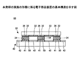
まず、図2を参照して、本発明の実施の形態に係る電子部品装置の基本構造を説明し、次に、図3乃至図5を参照して、該構造の具体的構造を説明する。
[Structure of electronic component equipment]
First, the basic structure of the electronic component device according to the embodiment of the present invention will be described with reference to FIG. 2, and then the specific structure of the structure will be described with reference to FIGS.
1.基本構造
図2に示すように、本発明の実施の形態に係る電子部品装置60にあっては、支持基板(パッケージ基板)30が、外部接続部たる半田バンプ34を介して回路配線基板(マザーボード)40に電気的に接続されている。
1. Basic Structure As shown in FIG. 2, in an
支持基板30は、ガラスエポキシ樹脂等の絶縁性樹脂を基材とし、その表面に銅(Cu)等からなる導電層が選択的に配設された配線用基板を複数積層して形成されている。
The
支持基板10において、図示を省略する半導体素子が実装される主面と反対側の主面上には、銅(Cu)を主成分とする銅(Cu)層部がフォトリソグラフィー法等により形成され、当該銅(Cu)層部上には、例えばニッケル(Ni)を主成分とするニッケル(Ni)層及び金(Au)を主成分とする金(Au)層部がこの順にめっき法により積層されて、これにより電極部32が形成されている。なお、支持基板30の当該主面であって、電極部32が形成されていない箇所には、ポリイミド等の絶縁膜33が形成されている。
In the support substrate 10, a copper (Cu) layer portion containing copper (Cu) as a main component is formed by a photolithography method or the like on the main surface opposite to the main surface on which a semiconductor element (not shown) is mounted. On the copper (Cu) layer portion, for example, a nickel (Ni) layer mainly composed of nickel (Ni) and a gold (Au) layer portion mainly composed of gold (Au) are laminated in this order by a plating method. Thus, the
電極部32上には、球状の外部接続用突起電極たる半田バンプ34が形成されている。半田バンプ34は、錫(Sn)を主成分とし、鉛(Pb)を含有しない。例えば、ビスマス(Bi)、インジウム(In)、亜鉛(Zn)、銀(Ag)、アンチモン(Sb)、銅(Cu)、及びニッケル(Ni)等から選択された少なくとも一種以上の金属が、半田バンプ34の添加成分として含まれていてもよい。半田バンプ34は、例えば、融点が217℃の錫(Sn)−3.0銀(Ag)−0.5銅(Cu)からなってもよい。
On the
半田ボール34が加熱融合されて、支持基板30が、回路配線基板40に電気的に接続される。
The
なお、電極部32を構成するニッケル(Ni)層と半田バンプ34の接合界面には、錫(Sn)−ニッケル(Ni)から成るバリア層36が形成されている。
A
支持基板30の下方には、ガラスエポキシ樹脂等の絶縁性樹脂を基材とし、その表面に銅(Cu)等からなる導電層が選択的に配設された配線回路基板40が設けられている。
Below the
配線回路基板40の主面であって、支持基板30に対向している面上には、銅(Cu)から成る電極41が形成されている。配線回路基板40の当該主面であって、電極41が形成されていない箇所には、ソルダーレジスト膜42が形成されている。
An
電極41上には、半田バンプ34の主成分である錫(Sn)と親和性の高い金属からなる金属部50が島状(凹凸状)に部分的に被覆形成されている。即ち、電極41と半田バンプ34との界面の一部に、金属部50が形成されている。
On the
金属部50は、例えば、コバルト(Co)、鉄(Fe)、ニッケル(Ni)、マンガン(Mn)等、錫(Sn)との親和性が高い金属材料からなる。
The
従って、金属部50により、電極41の構成材料である銅(Cu)と、半田バンプ34の構成材料である錫(Sn)との反応成長を抑制することができ、半田バンプ34中の錫(Sn)が銅(Cu)からなる電極41に拡散することを抑制することができる。
Accordingly, the
よって、錫(Sn)と銅(Cu)との化合物層が厚く形成されると、半田バンプ34と電極41との接合は脆くなるが、本例のように金属部50を設けることにより、金属部50が設けられた箇所においては、錫(Sn)と銅(Cu)との化合物層の厚さを薄くすることができる。硬くて脆い錫(Sn)と銅(Cu)との化合物層の成長を抑制することができるため、落下衝撃によって生じる動的歪みを緩和でき、クラックの発生を防止することができるため、支持基板10と配線回路基板40との接合信頼性の低下を防止することができる。
Therefore, when the compound layer of tin (Sn) and copper (Cu) is formed thick, the bonding between the
また、回路配線基板40とBGA型半導体装置の構成部品との熱膨張率の相違に起因して生じる半田バンプにかかる応力を緩和でき、回路配線基板40に対するBGA型半導体装置の支持基板10の実装構造の変形を防止することができる。
In addition, the stress applied to the solder bump caused by the difference in thermal expansion coefficient between the
更に、電極41上において、金属部50は島状(凹凸状)に部分的に被覆形成されているため、金属部50が設けられていない箇所では、半田バンプ34中の錫(Sn)の銅(Cu)からなる電極41に対する濡れ性を確保でき、半田溶融時において半田成分中の錫(Sn)と銅(Cu)が接触し、錫(Sn)と銅(Cu)との化合物層が形成され、錫(Sn)と銅(Cu)とは接合し、合金化することができる。
Furthermore, on the
即ち、本発明の実施の形態によれば、半田バンプ34中の錫(Sn)の銅(Cu)からなる電極41に対する濡れ性を確保しつつ、配線回路基板40と支持基板30との接合信頼性の低下を招く錫(Sn)と銅(Cu)との化合物層の成長を抑制することができる。
That is, according to the embodiment of the present invention, the bonding reliability between the printed
このような、本発明の実施の形態に係る電子部品装置60は、例えば、サーバ装置、ストレージ装置、ネットワーク基幹機器、携帯端末、パーソナル・コンピュータ等に搭載することができる。
Such an
2.具体的構造
次に、上述の基本構造を備えた電子部品装置における回路配線基板40の具体的構造(第1の例乃至第3の例)について、図3乃至図5を参照して説明する。なお、図3乃至図5において、図2に示した箇所と同じ箇所には同じ符号を付して、その詳細な説明を省略する。
2. Specific Structure Next, a specific structure (first example to third example) of the
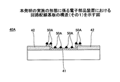
図3に示す第1の例に係る配線回路基板40Aにおいては、銅(Cu)からなる電極41上に、半田バンプ34(図2参照)の主成分である錫(Sn)と親和性の高い金属からなる金属部50Aが、無電解めっき法により、島状(凹凸状)に部分的に被覆形成されている。
In the printed
金属部50Aは、例えば、コバルト(Co)、コバルト(Co)−タングステン(W)、コバルト(Co)−リン(P)、コバルト(Co)−ホウ素(B)、コバルト(Co)−ニッケル(Ni)等のコバルト(Co)基の材料、又はニッケル(Ni)−リン(P)、ニッケル(Ni)−ホウ素(B)、ニッケル(Ni)−鉄(Fe)、ニッケル(Ni)−マンガン(Mn)、等のニッケル(Ni)基の材料からなる。
The
詳細は後述するが、フォトリソグラフィー技術を用いてレジストマスクを形成し、開口している電極41上に、無電解めっき法により金属部50Aが部分的に被覆されている。
Although details will be described later, a resist mask is formed by using a photolithography technique, and the
図4に示す第2の例に係る配線回路基板40Bにおいては、銅(Cu)からなる電極41上に、銅(Cu)からなるシード層45が例えばスパッタリング法により形成されている。そして、シード層45上に、半田バンプ34(図2参照)の主成分である錫(Sn)と親和性の高い金属からなる金属部50Bが、電解めっき法により、島状(凹凸状)に部分的に被覆形成されている。
In the printed
金属部50Bは、例えば、鉄(Fe)、ニッケル(Ni)、マンガン(Mn)、鉄(Fe)−マンガン(Mn)等、錫(Sn)との親和性が高い金属材料からなる。
The
詳細は後述するが、電解めっきにおいて電流密度及びめっき時間を調整することにより、銅(Cu)からなるシード層45上に金属部50Bが部分的に被覆されている。
Although details will be described later, the
図5に示す第3の例に係る配線回路基板40Cでは、銅(Cu)からなる電極41’に、高さが約1μmの頂部を有する凸部41’aが部分的に形成されており、電極41’の上面が粗面化されている。そして、凸部41’aに、金属部50Cが、例えば電解めっき法により形成されている。なお、図5(b)は、図5(a)において点線Aで囲んだ部分を拡大して示す。
In the printed
詳細は後述するが、凸部41’aは、例えば、無機酸化物砥石粉末が設けられたサンドブラスト等の機械研磨法又はアルゴン(Ar)プラズマ等の気相式若しくは酸性溶液等の液相式のエッチング法等により形成される。金属部50Cは、例えば、鉄(Fe)、ニッケル(Ni)、マンガン(Mn)、鉄(Fe)−マンガン(Mn)等、錫(Sn)との親和性が高い金属材料からなる。
Although details will be described later, the
図3又は図4に示す構造は、無電解めっき又は電解めっき法を用いているため、当該構造を容易に形成することができる。一方、図5に示す構造は、電極41’上に部分的に凸部41’aが形成されているため、確実に金属部50Cを形成することができ、より確実に錫(Sn)と銅(Cu)との化合物層の成長を抑制することができる。
Since the structure shown in FIG. 3 or 4 uses an electroless plating or an electrolytic plating method, the structure can be easily formed. On the other hand, in the structure shown in FIG. 5, since the
図6に、金属部50A(50B又は50C)が形成された電極41(シード層45、又は電極41’)を上側から見た状態を示す。図6に示すように、電極41(シード層45又は電極41’)の上面において、金属部50A(50B又は50C)が部分的に形成されている。
FIG. 6 shows a state where the electrode 41 (
本発明の発明者は、金属部50A(50B又は50C)の全面積の、電極41(シード層45又は電極41’)の上面の面積に対する割合、即ち、電極41(シード層45又は電極41’)の上面の面積/金属部50A(50B又は50C)の全面積につき、シミュレーションを行った結果、当該割合が約30乃至70%である場合が望ましいことを把握した。これについて、図7を参照して説明する。
The inventor of the present invention determines the ratio of the total area of the
図7は、本発明の発明者のシミュレーション結果に基づく、金属部50A(50B又は50C)の全面積の、電極41(シード層45又は電極41’)の上面の面積に対する割合と、(1)線Bで示す、半田バンプ34(図2参照)と電極41(シード層45又は電極41’)との引張応力(密着力)及び、(2)線Cで示す、半田バンプ34と金属部50A(50B又は50C)との接合界面と平行方向の応力たる剪断応力と、の関係を示す。
FIG. 7 shows the ratio of the total area of the
なお、図7に示すグラフにおいて、左側の縦軸は、半田バンプ34(図2参照)と電極41(シード層45又は電極41’)との引張応力(MPa)を、右側の縦軸は、半田バンプ34と金属部50A(50B又は50C)との接合界面と平行方向の応力たる剪断応力(MPa)を示す。
In the graph shown in FIG. 7, the left vertical axis represents the tensile stress (MPa) between the solder bump 34 (see FIG. 2) and the electrode 41 (
図7に示すように、金属部50A(50B又は50C)の全面積の、電極41(シード層45又は電極41’)の上面の面積に対する割合が約30乃至70%のときに、半田バンプ34(図2参照)と電極41(シード層45又は電極41’)との引張応力(密着力)が約40MPa以上であって、半田バンプ34と金属部50A(50B又は50C)との接合界面と平行方向の応力たる剪断応力が約50MPa以上となり、望ましいことが分かる。
As shown in FIG. 7, when the ratio of the total area of the
なお、詳細は後述するが、図3に示す例の金属部50Aの全面積の、電極41の上面の面積に対する割合は、無電解めっき法において用いられるレジストマスクの開口率によって調整することができる。また、図4に示す例の金属部50Bの全面積の、シード層45の上面の面積に対する割合は、電解めっき法における、電流密度とめっき時間によって調整することができる。
In addition, although mentioned later for details, the ratio with respect to the area of the upper surface of the
[電子部品装置の製造方法]
次に、上述の第1乃至第3の例に係る配線回路基板40A乃至40Cを備えた電子部品装置の製造方法について説明する。
[Method of manufacturing electronic component device]
Next, a method for manufacturing an electronic component device including the printed
1.配線回路基板40Aを備えた電子部品装置の製造方法
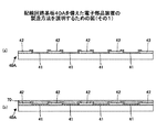
図8乃至図11を参照して、配線回路基板40Aを備えた電子部品装置の製造方法について説明する。
1. Method for Manufacturing Electronic Component Device Comprising Wiring
まず、図8(a)に示すように、ガラスエポキシ樹脂等の絶縁性樹脂を基材とし、その表面に銅(Cu)等からなる導電層が選択的に配設された配線回路基板40が用意される。配線回路基板40の一方の主面(上面)上には、銅(Cu)から成る電極41が形成されている。配線回路基板40の当該主面であって、電極41が形成されていない箇所には、ソルダーレジスト膜42が形成されている。
First, as shown in FIG. 8A, there is a printed
次に、図8(b)に示すように、電極41及びソルダーレジスト膜42上に、感光性ドライフィルムレジスト70を形成する。
Next, as shown in FIG. 8B, a photosensitive dry film resist 70 is formed on the
次いで、図9(c)に示すように、露光処理・現像処理により、電極41上面が部分的に開口するように感光性ドライフィルムレジスト70をパターニングする。このとき、電極41の上面の面積に対する、開口部の面積の割合を調整することにより、後述する工程で形成される金属部50Aの配設面積を調整することができる。電極41の上面の面積に対する、開口部の面積の割合は、例えば約30乃至70%に設定することができる。
Next, as shown in FIG. 9C, the photosensitive dry film resist 70 is patterned so that the upper surface of the
しかる後、図9(d)に示すように、感光性ドライフィルムレジスト70の開口部に、半田バンプ34(図2参照)の主成分である錫(Sn)と親和性の高い金属からなる金属部50Aを、無電解めっき法により形成する。
Thereafter, as shown in FIG. 9D, a metal made of a metal having a high affinity for tin (Sn), which is the main component of the solder bump 34 (see FIG. 2), is formed in the opening of the photosensitive dry film resist 70. The
金属部50Aは、例えば、コバルト(Co)、コバルト(Co)−タングステン(W)、コバルト(Co)−リン(P)、コバルト(Co)−ホウ素(B)、コバルト(Co)−ニッケル(Ni)等のコバルト(Co)基の材料、又はニッケル(Ni)−リン(P)、ニッケル(Ni)−ホウ素(B)、ニッケル(Ni)−鉄(Fe)、ニッケル(Ni)−マンガン(Mn)、等のニッケル(Ni)基の材料からなる。
The
また、めっき条件として、例えば、めっき浴の温度を90℃に、pHを9.3に、また、めっき時間を20分に設定することができる。 As plating conditions, for example, the temperature of the plating bath can be set to 90 ° C., the pH can be set to 9.3, and the plating time can be set to 20 minutes.
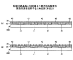
次いで、図9(d)に示すように感光性ドライフィルムレジスト70を剥離すると、図10(e)に示すように、銅(Cu)からなる電極41上に、半田バンプ34(図2参照)の主成分である錫(Sn)と親和性の高い金属からなる金属部50Aが、島状(凹凸状)に部分的に被覆形成されてなる構造が形成される。
Next, when the photosensitive dry film resist 70 is peeled off as shown in FIG. 9D, the solder bumps 34 (see FIG. 2) are formed on the
しかる後、金属部50Aが形成された電極41上に錫(Sn)−3.0銀(Ag)−0.5銅(Cu)からなる半田ペーストをスクリーン印刷法により形成する。
Thereafter, a solder paste made of tin (Sn) -3.0 silver (Ag) -0.5 copper (Cu) is formed on the
一方、図10(f)に示すように、図示を所略する半導体素子が実装された支持基板30が用意される。
On the other hand, as shown in FIG. 10F, a
支持基板30は、ガラスエポキシ樹脂等の絶縁性樹脂を基材とし、その表面に銅(Cu)等からなる導電層が選択的に配設された配線用基板を複数積層して形成されている。
The
支持基板30において、図示を省略する半導体素子が実装される主面と反対側の主面上には、銅(Cu)を主成分とする銅(Cu)層部がフォトリソグラフィー法等により形成され、当該銅(Cu)層部上には、例えばニッケル(Ni)を主成分とするニッケル(Ni)層及び金(Au)を主成分とする金(Au)層部がこの順にめっき法により積層されて、これにより電極部32が形成されている。なお、支持基板30の当該主面であって、電極部32が形成されていない箇所には、ポリイミド等の絶縁膜33が形成されている。
In the
電極部32上には、球状の外部接続用突起電極たる半田バンプ34が形成されている。半田バンプ34は、錫(Sn)を主成分とし、鉛(Pb)を含有せず、ビスマス(Bi)、インジウム(In)、亜鉛(Zn)、銀(Ag)、アンチモン(Sb)、銅(Cu)、及びニッケル(Ni)等から選択された少なくとも一種以上の金属からなる添加成分を含んでなる。半田バンプ34は、例えば、錫(Sn)−3.0銀(Ag)−0.5銅(Cu)からなってもよい。
On the
なお、電極部32を構成するニッケル(Ni)層と半田バンプ34の接合界面には、錫(Sn)−ニッケル(Ni)から成るバリア層36が形成されている。
A
図10(f)に示すように、支持基板30に接合された半田バンプ34と、配線回路基板40の主面上に形成された電極41とを位置合わせして両者を接続し、窒素雰囲気下にあるコンベア炉において、半田バンプ34の融点(約217℃)以上、最高温度250℃以下の温度条件の下、約2分間リフロー加熱処理を施し、半田バンプ34を加熱融合する。
As shown in FIG. 10 (f), the solder bumps 34 bonded to the
その結果、図11(g)に示すように、半田バンプ34と電極41とが金属部50Aを介在させて接合し、支持基板30が、半田バンプ34を介して回路配線基板40に接続されてなる電子部品装置を製造することができる。
As a result, as shown in FIG. 11G, the
本発明の発明者は、上記の無電解めっき法を用いて金属部50Aが形成された回路配線基板40を備えた電子部品装置と、金属部50Aが形成されていない回路配線基板を備えた電子部品装置とにつき、2種類の信頼性試験を行った。
The inventor of the present invention provides an electronic component device including a
第1に、約30分間−(マイナス)55℃の環境下に配設し、次いで、約30分間125℃の環境下に配設するという温度サイクルを500回繰り返し、抵抗上昇等の有無を確認した。 First, repeat the temperature cycle for about 30 minutes-(minus) in an environment of 55 ° C, then place in an environment of 125 ° C for about 30 minutes, and check for resistance increase, etc. did.
金属部50Aが形成されていない回路配線基板を備えた5つの電子部品装置のうち、3個が抵抗上昇等、信頼性の低下が見られた。
Among the five electronic component devices provided with the circuit wiring board on which the
また、無電解めっき法を用い、更に、電極41の上面の面積に対する金属部50Aの配設面積の割合が、約30%未満又は70%以上の場合には、金属部50Aが形成された回路配線基板40を備えた5つの電子部品装置のうち、3個が抵抗上昇等、信頼性の低下が見られた。
Further, when the ratio of the arrangement area of the
一方、無電解めっき法を用い、更に、電極41の上面の面積に対する金属部50Aの配設面積の割合が、約30%乃至70%の場合には、金属部50Aが形成された回路配線基板40を備えた5つの電子部品装置のどれにも抵抗上昇等、信頼性の低下は発見されなかった。
On the other hand, when the ratio of the arrangement area of the
第2に、高さ約10cmからの自由落下衝撃試験を200サイクル繰り返し、抵抗上昇等の有無を確認した。 Second, the free drop impact test from a height of about 10 cm was repeated 200 cycles to confirm the presence or absence of resistance increase.
金属部50Aが形成されていない回路配線基板を備えた5つの電子部品装置のうち、4個が抵抗上昇等、信頼性の低下が見られた。
Among the five electronic component devices provided with the circuit wiring board on which the
また、無電解めっき法を用い、更に、電極41の上面の面積に対する金属部50Aの配設面積の割合が、約30%未満又は70%以上の場合には、金属部50Aが形成された回路配線基板40を備えた5つの電子部品装置の全てに抵抗上昇等、信頼性の低下が見られた。
Further, when the ratio of the arrangement area of the
一方、無電解めっき法を用い、更に、電極41の上面の面積に対する金属部50Aの配設面積の割合が、約30%乃至70%の場合には、金属部50Aが形成された回路配線基板40を備えた5つの電子部品装置のどれにも抵抗上昇等、信頼性の低下は発見されなかった。
On the other hand, when the ratio of the arrangement area of the
このように、図8乃至図11に示す方法によれば、信頼性の高い電子部品装置を簡易な方法により、製造することができる。 As described above, according to the method shown in FIGS. 8 to 11, a highly reliable electronic component device can be manufactured by a simple method.
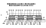
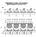
2.配線回路基板40Bを備えた電子部品装置の製造方法
図12乃至図16を参照して、配線回路基板40Bを備えた電子部品装置の製造方法について説明する。なお、図12乃至図16において、図8乃至図11を参照して説明した箇所と同じ箇所については、同じ符号を付してその説明を省略する。
2. Manufacturing Method of Electronic Component Device Having Wiring
まず、図12(a)に示すように、配線回路基板40が用意される。配線回路基板40の一方の主面(上面)上には、銅(Cu)から成る電極41が形成されている。配線回路基板40の当該主面であって、電極41が形成されていない箇所には、ソルダーレジスト膜42が形成されている。
First, as shown in FIG. 12A, a printed
次いで、図12(b)に示すように、電極41及びソルダーレジスト膜42上に、銅(Cu)からなるシード層45を例えばスパッタリング法により形成する。
Next, as shown in FIG. 12B, a
次に、図13(c)に示すように、シード層45上に、感光性ドライフィルムレジスト70を形成する。
Next, as shown in FIG. 13C, a photosensitive dry film resist 70 is formed on the
次いで、図13(d)に示すように、露光処理・現像処理により、電極41が位置する箇所における感光性ドライフィルムレジスト70が部分的に開口するように、感光性ドライフィルムレジスト70をパターニングする。
Next, as shown in FIG. 13D, the photosensitive dry film resist 70 is patterned by exposure processing / development processing so that the photosensitive dry film resist 70 is partially opened at the position where the
しかる後、図14(e)に示すように、感光性ドライフィルムレジスト70の開口部に、半田バンプ34(図2参照)の主成分である錫(Sn)と親和性の高い金属からなる金属部50Bを、電解めっき法により形成する。
Thereafter, as shown in FIG. 14 (e), a metal made of a metal having a high affinity with tin (Sn), which is the main component of the solder bump 34 (see FIG. 2), in the opening of the photosensitive dry film resist 70. The
金属部50Bは、例えば、鉄(Fe)、ニッケル(Ni)、マンガン(Mn)、鉄(Fe)−マンガン(Mn)等、錫(Sn)との親和性が高い金属材料からなる。
The
当該電解めっきにおいて電流密度及びめっき時間を調整することにより、金属部50Bの全面積の、シード層45の上面の面積に対する割合を約30乃至70%に設定することができる。
By adjusting the current density and plating time in the electrolytic plating, the ratio of the total area of the
例えば、金属部50Bの形成にあたり、ニッケル(Ni)めっきを形成する場合、めっき条件として、めっき浴の温度を約50℃、電流密度を約1乃至5A/dm2、めっき時間を約10分に設定することができる。また、ニッケル(Ni)の含有量が約80wt%であるニッケル(Ni)−コバルト(Co)合金のめっきを形成する場合、めっき浴の温度を約50℃、電流密度を約10A/dm2、めっき時間を約1分に設定することができる。更に、ニッケル(Ni)の含有量が約42wt%であるニッケル(Ni)−鉄(Fe)合金のめっきを形成する場合、めっき浴の温度を約50℃、電流密度を約10A/dm2、めっき時間を約1分に設定することができる。
For example, when forming nickel (Ni) plating for forming the
次いで、図14(f)に示すように感光性ドライフィルムレジスト70を剥離すると、図15(g)に示すように、銅(Cu)からなるシード層45上に、半田バンプ34(図2参照)の主成分である錫(Sn)と親和性の高い金属からなる金属部50Bが、島状(凹凸状)に部分的に被覆形成されてなる構造が形成される。
Next, when the photosensitive dry film resist 70 is peeled off as shown in FIG. 14F, the solder bumps 34 (see FIG. 2) are formed on the
しかる後、金属部50Aが形成されたシード層45上に錫(Sn)−3.0銀(Ag)−0.5銅(Cu)からなる半田ペーストをスクリーン印刷法により形成する。
Thereafter, a solder paste made of tin (Sn) -3.0 silver (Ag) -0.5 copper (Cu) is formed on the
一方、図15(h)に示すように、図示を所略する半導体素子が実装された支持基板30が用意される。
On the other hand, as shown in FIG. 15H, a
支持基板30において、図示を省略する半導体素子が実装される主面と反対側の主面上には、銅(Cu)を主成分とする銅(Cu)層部がフォトリソグラフィー法等により形成され、当該銅(Cu)層部上には、例えばニッケル(Ni)を主成分とするニッケル(Ni)層及び金(Au)を主成分とする金(Au)層部がこの順にめっき法により積層されて、これにより電極部32が形成されている。なお、支持基板30の当該主面であって、電極部32が形成されていない箇所には、ポリイミド等の絶縁膜33が形成されている。
In the
電極部32上には、球状の外部接続用突起電極たる半田バンプ34が形成されている。半田バンプ34は、錫(Sn)を主成分とし、鉛(Pb)を含有せず、ビスマス(Bi)、インジウム(In)、亜鉛(Zn)、銀(Ag)、アンチモン(Sb)、銅(Cu)、及びニッケル(Ni)等から選択された少なくとも一種以上の金属からなる添加成分を含んでなる。半田バンプ34は、例えば、錫(Sn)−3.0銀(Ag)−0.5銅(Cu)からなってもよい。
On the
なお、電極部32を構成するニッケル(Ni)層と半田バンプ34の接合界面には、錫(Sn)−ニッケル(Ni)から成るバリア層36が形成されている。
A
図15(h)に示すように、支持基板30に接合された半田バンプ34と、配線回路基板40の主面上に形成された電極41とを位置合わせして両者を接続し、窒素雰囲気下にあるコンベア炉において、半田バンプ34の融点(約217℃)以上、最高温度250℃以下の温度条件の下、約2分間リフロー加熱処理を施し、半田バンプ34を加熱融合する。
As shown in FIG. 15 (h), the solder bumps 34 bonded to the
その結果、図16(i)に示すように、半田バンプ34と電極41とが金属部50Bを介在させて接合し、支持基板30が、半田バンプ34を介して回路配線基板40に接続されてなる電子部品装置を製造することができる。
As a result, as shown in FIG. 16I, the
本発明の発明者は、上記の電解めっき法を用いて金属部50Bが形成された回路配線基板40を備えた電子部品装置と、金属部50Bが形成されていない回路配線基板を備えた電子部品装置とにつき、2種類の信頼性試験を行った。
The inventor of the present invention provides an electronic component device including a
第1に、約30分間−(マイナス)55℃の環境下に配設し、次いで、約30分間125℃の環境下に配設するという温度サイクルを500回繰り返し、抵抗上昇等の有無を確認した。 First, repeat the temperature cycle for about 30 minutes-(minus) in an environment of 55 ° C, then place in an environment of 125 ° C for about 30 minutes, and check for resistance increase, etc. did.
金属部50Bが形成されていない回路配線基板を備えた5つの電子部品装置のうち、3個が抵抗上昇等、信頼性の低下が見られた。
Among the five electronic component devices provided with the circuit wiring board on which the
また、電解めっき法を用いてニッケル(Ni)めっきにより金属部50Bを形成し、更に、電極41の上面の面積に対する金属部50Bの配設面積の割合が、約30%未満又は70%以上の場合には、金属部50Bが形成された回路配線基板40を備えた5つの電子部品装置のうち、3個が抵抗上昇等、信頼性の低下が見られた。
Further, the
一方、電解めっき法を用いてニッケル(Ni)めっきにより金属部50Bを形成し、更に、電極41の上面の面積に対する金属部50Bの配設面積の割合が、約30%乃至70%の場合には、金属部50Bが形成された回路配線基板40を備えた5つの電子部品装置のどれにも抵抗上昇等、信頼性の低下は発見されなかった。
On the other hand, when the
また、電解めっき法を用いてニッケル(Ni)−コバルト(Co)合金のめっきにより金属部50Bを形成した場合には、金属部50Bが形成された回路配線基板40を備えた5つの電子部品装置のどれにも抵抗上昇等、信頼性の低下は発見されなかった。
Further, when the
また、電解めっき法を用いてニッケル(Ni)−鉄(Fe)合金のめっきにより金属部50Bを形成した場合には、金属部50Bが形成された回路配線基板40を備えた5つの電子部品装置のどれにも抵抗上昇等、信頼性の低下は発見されなかった。
Further, when the
第2に、高さ約10cmからの自由落下衝撃試験を200サイクル繰り返し、抵抗上昇等の有無を確認した。 Second, the free drop impact test from a height of about 10 cm was repeated 200 cycles to confirm the presence or absence of resistance increase.
金属部50Bが形成されていない回路配線基板を備えた5つの電子部品装置のうち、4個が抵抗上昇等、信頼性の低下が見られた。
Among the five electronic component devices provided with the circuit wiring board on which the
また、電解めっき法を用いてニッケル(Ni)めっきにより金属部50Bを形成し、更に、電極41の上面の面積に対する金属部50Bの配設面積の割合が、約30%未満又は70%以上の場合には、金属部50Bが形成された回路配線基板40を備えた5つの電子部品装置の全てに抵抗上昇等、信頼性の低下が見られた。
Further, the
一方、電解めっき法を用いてニッケル(Ni)めっきにより金属部50Bを形成し、更に、電極41の上面の面積に対する金属部50Bの配設面積の割合が、約30%乃至70%の場合には、金属部50Bが形成された回路配線基板40を備えた5つの電子部品装置のどれにも抵抗上昇等、信頼性の低下は発見されなかった。
On the other hand, when the
また、電解めっき法を用いてニッケル(Ni)−コバルト(Co)合金のめっきにより金属部50Bを形成した場合には、金属部50Bが形成された回路配線基板40を備えた5つの電子部品装置のどれにも抵抗上昇等、信頼性の低下は発見されなかった。
Further, when the
また、電解めっき法を用いてニッケル(Ni)−鉄(Fe)合金のめっきにより金属部50Bを形成した場合には、金属部50Bが形成された回路配線基板40を備えた5つの電子部品装置のどれにも抵抗上昇等、信頼性の低下は発見されなかった。
Further, when the
このように、図12乃至図16に示す方法によれば、信頼性の高い電子部品装置を簡易な方法により、製造することができる。 Thus, according to the method shown in FIGS. 12 to 16, a highly reliable electronic component device can be manufactured by a simple method.
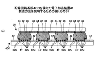
3.配線回路基板40Cを備えた電子部品装置の製造方法
図17乃至図19を参照して、配線回路基板40Cを備えた電子部品装置の製造方法について説明する。なお、図17乃至図19において、図8乃至図16を参照して説明した箇所と同じ箇所については、同じ符号を付してその説明を省略する。
3. Manufacturing Method of Electronic Component Device Having Wiring
まず、図17(a)に示すように、配線回路基板40Cが用意される。配線回路基板40Cの一方の主面(上面)上には、銅(Cu)から成る電極41’が形成されている。配線回路基板40Cの当該主面であって、電極41’が形成されていない箇所には、ソルダーレジスト膜42が形成されている。
First, as shown in FIG. 17A, a printed
次に、図17(b)に示すように、機械研磨法又はエッチング法等により、電極41’に、高さが約1μmの頂部を有する凸部41’aを部分的に形成して、電極41’の上面を粗面化する。
Next, as shown in FIG. 17B, the
機械研磨法として、例えば、アルミナ等の無機酸化物砥石粉末が設けられたサンドブラストを用いることができる。#120のサンドブラストを用いることにより、高さが約5μmの頂部を有する凸部41’aを形成することができる。また、エッチング法として、例えば、アルゴン(Ar)プラズマ等の気相式若しくは酸性溶液等の液相式のエッチング法を用いて凸部41’aを形成することができる。
As the mechanical polishing method, for example, sand blasting provided with inorganic oxide grinding stone powder such as alumina can be used. By using # 120 sandblast, the
しかる後、例えば電解めっき法により、凸部41’aに、金属部50Cを形成する。金属部50Cは、例えば、鉄(Fe)、ニッケル(Ni)、マンガン(Mn)、鉄(Fe)−マンガン(Mn)等、錫(Sn)との親和性が高い金属材料からなる。金属部50Cの形成にあたり、ニッケル(Ni)めっきを形成する場合、めっき条件として、めっき浴の温度を約50℃、電流密度を約1乃至5A/dm2、めっき時間を約5分に設定することができる。
Thereafter, the
このようにして、図18(c)に示すように、銅(Cu)からなる電極41’の凸部41’a上に、半田バンプ34(図2参照)の主成分である錫(Sn)と親和性の高い金属からなる金属部50Cが、島状(凹凸状)に部分的に被覆形成されてなる構造が形成される。なお、電極41’の凸部41’a上への金属部50Cの形成にあっては、無電解めっき法を用いてもよい。
In this way, as shown in FIG. 18C, tin (Sn), which is the main component of the solder bump 34 (see FIG. 2), is formed on the
しかる後、金属部50Cが形成された電極41’上に錫(Sn)−3.0銀(Ag)−0.5銅(Cu)からなる半田ペーストをスクリーン印刷法により形成する。
Thereafter, a solder paste made of tin (Sn) -3.0 silver (Ag) -0.5 copper (Cu) is formed on the
一方、図18(d)に示すように、図示を所略する半導体素子が実装された支持基板30が用意される。
On the other hand, as shown in FIG. 18D, a
支持基板30において、図示を省略する半導体素子が実装される主面と反対側の主面上には、銅(Cu)を主成分とする銅(Cu)層部がフォトリソグラフィー法等により形成され、当該銅(Cu)層部上には、例えばニッケル(Ni)を主成分とするニッケル(Ni)層及び金(Au)を主成分とする金(Au)層部がこの順にめっき法により積層されて、これにより電極部32が形成されている。なお、支持基板30の当該主面であって、電極部32が形成されていない箇所には、ポリイミド等の絶縁膜33が形成されている。
In the
電極部32上には、球状の外部接続用突起電極たる半田バンプ34が形成されている。半田バンプ34は、錫(Sn)を主成分とし、鉛(Pb)を含有せず、ビスマス(Bi)、インジウム(In)、亜鉛(Zn)、銀(Ag)、アンチモン(Sb)、銅(Cu)、及びニッケル(Ni)等から選択された少なくとも一種以上の金属からなる添加成分を含んでなる。半田バンプ34は、例えば、錫(Sn)−3.0銀(Ag)−0.5銅(Cu)からなってもよい。
On the
なお、電極部32を構成するニッケル(Ni)層と半田バンプ34の接合界面には、錫(Sn)−ニッケル(Ni)から成るバリア層36が形成されている。
A
図18(d)に示すように、支持基板30に接合された半田バンプ34と、配線回路基板40Cの主面上に形成された電極41’とを位置合わせして両者を接続し、窒素雰囲気下にあるコンベア炉において、半田バンプ34の融点(約217℃)以上、最高温度250℃以下の温度条件の下、約2分間リフロー加熱処理を施し、半田バンプ34を加熱融合する。
As shown in FIG. 18D, the solder bumps 34 bonded to the
その結果、図19(e)に示すように、半田バンプ34と電極41とが金属部50Cを介在させて接合し、支持基板30が、半田バンプ34を介して回路配線基板40Cに接続されてなる電子部品装置を製造することができる。
As a result, as shown in FIG. 19E, the
本発明の発明者は、上記の電解めっき法を用いて金属部50Cが形成された回路配線基板40を備えた電子部品装置と、金属部50Cが形成されていない回路配線基板を備えた電子部品装置とにつき、2種類の信頼性試験を行った。
The inventor of the present invention provides an electronic component device including a
第1に、約30分間−(マイナス)55℃の環境下に配設し、次いで、約30分間125℃の環境下に配設するという温度サイクルを500回繰り返し、抵抗上昇等の有無を確認した。 First, repeat the temperature cycle for about 30 minutes-(minus) in an environment of 55 ° C, then place in an environment of 125 ° C for about 30 minutes, and check for resistance increase, etc. did.
金属部50Cが形成されていない回路配線基板を備えた5つの電子部品装置のうち、3個が抵抗上昇等、信頼性の低下が見られた。
Among the five electronic component devices provided with the circuit wiring board on which the
一方、アルミナ#120のサンドブラストを用いて、高さが約1μmの頂部を有する凸部41’aを形成し、当該凸部41’aに、電解めっき法により、ニッケル(Ni)の金属部50Cが形成された回路配線基板40Cを備えた5つの電子部品装置のどれにも抵抗上昇等、信頼性の低下は発見されなかった。
On the other hand, a
第2に、高さ約10cmからの自由落下衝撃試験を200サイクル繰り返し、抵抗上昇等の有無を確認した。 Second, the free drop impact test from a height of about 10 cm was repeated 200 cycles to confirm the presence or absence of resistance increase.
金属部50Cが形成されていない回路配線基板を備えた5つの電子部品装置のうち、4個が抵抗上昇等、信頼性の低下が見られた。
Of the five electronic component devices provided with the circuit wiring board in which the
一方、アルミナ#120のサンドブラストを用いて、高さが約1μmの頂部を有する凸部41’aを形成し、当該凸部41’aに、電解めっき法により、ニッケル(Ni)の金属部50Cが形成された回路配線基板40Cを備えた5つの電子部品装置のどれにも抵抗上昇等、信頼性の低下は発見されなかった。
On the other hand, a
このようにして、図17乃至図19に示す方法により、信頼性の高い電子部品装置を製造することができる。 In this manner, a highly reliable electronic component device can be manufactured by the method shown in FIGS.
以上、本発明の実施の形態について詳述したが、本発明は特定の実施形態に限定されるものではなく、特許請求の範囲に記載された本発明の要旨の範囲内において、種々の変形及び変更が可能である。 Although the embodiment of the present invention has been described in detail above, the present invention is not limited to the specific embodiment, and various modifications and changes are within the scope of the gist of the present invention described in the claims. It can be changed.
また、上述の例では、支持基板30と回路配線基板40とは、半田バンプ34を介して接続されているが、本発明はかかる例に限定されない。
In the above example, the
例えば、錫(Sn)を主成分とし、ビスマス(Bi)、インジウム(In)、亜鉛(Zn)、銀(Ag)、アンチモン(Sb)、銅(Cu)、及びニッケル(Ni)等から選択された少なくとも一種以上の金属からなる添加成分を含んでなる半田ペーストにより、支持基板30と回路配線基板40とが接続されてなる構造に対しても、本発明を適用することができる。
For example, tin (Sn) as a main component and selected from bismuth (Bi), indium (In), zinc (Zn), silver (Ag), antimony (Sb), copper (Cu), nickel (Ni), etc. The present invention can also be applied to a structure in which the
以上の説明に関し、更に以下の項を開示する。
(付記1)
銅(Cu)を含む電極を主面に備えた回路配線基板と、
錫(Sn)を含み、前記電極に接続される外部接続部を主面に備えた電子部品と、を有し、
前記電極と前記外部接続部との界面の一部に、錫(Sn)と親和性を有する金属部が形成されていることを特徴とする電子部品装置。
(付記2)
付記1記載の電子部品装置であって、
前記金属部は、前記回路配線基板の前記電極上に島状に形成されていることを特徴とする電子部品装置。
(付記3)
付記1又は2いずれか一項記載の電子部品装置であって、
前記金属部は、コバルト(Co)、鉄(Fe)、ニッケル(Ni)、又はマンガン(Mn)を含むことを特徴とする電子部品装置。
(付記4)
付記1乃至3いずれか一項記載の電子部品装置であって、
前記金属部の全面積の、前記電極の上面の面積に対する割合は、約30乃至70%であることを特徴とする電子部品装置。
(付記5)
銅(Cu)を含む電極が主面に設けられ、
錫(Sn)を含む電子部品の外部接続部が前記電極に接続されて前記電子部品が実装される回路配線基板であって、
前記電極上に、前記錫(Sn)と親和性を有する金属部が形成されていることを特徴とする回路配線基板。
(付記6)
電子部品装置の製造方法であって、
回路配線基板の主面に設けられた銅(Cu)を含む電極上に、錫(Sn)と親和性を有する金属部を形成する工程と、
加熱しながら、前記錫(Sn)を含む電子部品の主面に設けられた外部接続部を、前記電極に接続し、前記金属部を介在させて前記外部接続部と前記電極とを接合する工程と、を含むことを特徴とする電子部品装置の製造方法。
(付記7)
付記6記載の電子部品装置の製造方法であって、
前記金属部は、無電解めっき法により、前記回路配線基板の前記電極上に島状に形成されることを特徴とする電子部品装置の製造方法。
(付記8)
付記6記載の電子部品装置の製造方法であって、
前記金属部を形成する工程の前に、前記電極上に凸部を形成する工程を更に有し、
前記金属部を形成する工程において、前記金属部は前記凸部上に電解めっき法又は無電解めっき法により形成されることを特徴とする電子部品装置の製造方法。
(付記9)
付記8記載の電子部品装置の製造方法であって、
前記凸部は、機械研磨法又はエッチング法によって、前記電極上に形成されることを特徴する電子部品装置の製造方法。
Regarding the above description, the following items are further disclosed.
(Appendix 1)
A circuit wiring board having an electrode containing copper (Cu) on its main surface;
An electronic component that includes tin (Sn) and includes an external connection portion connected to the electrode on a main surface;
An electronic component device, wherein a metal part having an affinity for tin (Sn) is formed at a part of an interface between the electrode and the external connection part.
(Appendix 2)
An electronic component device according to
The metal part is formed in an island shape on the electrode of the circuit wiring board.
(Appendix 3)
The electronic component device according to any one of
The electronic part device, wherein the metal part includes cobalt (Co), iron (Fe), nickel (Ni), or manganese (Mn).
(Appendix 4)
The electronic component device according to any one of
The ratio of the total area of the metal part to the area of the upper surface of the electrode is about 30 to 70%.
(Appendix 5)
An electrode containing copper (Cu) is provided on the main surface,
An external connection part of an electronic component containing tin (Sn) is connected to the electrode and is a circuit wiring board on which the electronic component is mounted,
A circuit wiring board, wherein a metal part having affinity for the tin (Sn) is formed on the electrode.
(Appendix 6)
A method for manufacturing an electronic component device, comprising:
Forming a metal part having an affinity for tin (Sn) on an electrode containing copper (Cu) provided on the main surface of the circuit wiring board;
A step of connecting an external connection portion provided on a main surface of the electronic component containing tin (Sn) to the electrode and heating the external connection portion and the electrode through the metal portion while heating. And a method of manufacturing an electronic component device.
(Appendix 7)
A method of manufacturing an electronic component device according to appendix 6,
The method of manufacturing an electronic component device, wherein the metal part is formed in an island shape on the electrode of the circuit wiring board by an electroless plating method.
(Appendix 8)
A method of manufacturing an electronic component device according to appendix 6,
Before the step of forming the metal part, further comprising the step of forming a convex portion on the electrode,
In the step of forming the metal part, the metal part is formed on the convex part by an electrolytic plating method or an electroless plating method.
(Appendix 9)
A method for manufacturing an electronic component device according to appendix 8, wherein
The method of manufacturing an electronic component device, wherein the convex portion is formed on the electrode by a mechanical polishing method or an etching method.
30 支持基板
34 半田バンプ
40 回路配線基板
41、41’ 電極
41’a 凸部
45 シード層
50、50A、50B、50C 金属部
60 電子部品装置
30
Claims (7)
錫(Sn)を含み、前記電極に接続される外部接続部を主面に備えた電子部品と、を有し、
前記電極と前記外部接続部との界面の一部に、前記電極と前記外部接続部との反応成長を抑制する、錫との親和性を有する金属部が形成されていることを特徴とする電子部品装置。 A circuit wiring board having an electrode containing copper (Cu) on its main surface;
An electronic component that includes tin (Sn) and includes an external connection portion connected to the electrode on a main surface;
An electron having an affinity for tin that suppresses reaction growth between the electrode and the external connection portion is formed at a part of an interface between the electrode and the external connection portion. Parts device.
前記金属部は、前記回路配線基板の前記電極上に島状に形成されていることを特徴とする電子部品装置。 The electronic component device according to claim 1,
The metal part is formed in an island shape on the electrode of the circuit wiring board.
前記金属部は、コバルト(Co)、鉄(Fe)、ニッケル(Ni)、又はマンガン(Mn)を含むことを特徴とする電子部品装置。 The electronic component device according to claim 1, wherein
The electronic part device, wherein the metal part includes cobalt (Co), iron (Fe), nickel (Ni), or manganese (Mn).
前記金属部は、前記電極上に形成される凸部の上に形成されることを特徴とする電子部品装置。 The electronic component device according to any one of claims 1 to 3,
The electronic component device according to claim 1, wherein the metal part is formed on a convex part formed on the electrode.
前記金属部の全面積の、前記電極の上面の面積に対する割合は、30乃至70%であることを特徴とする電子部品装置。 An electronic component device according to any one of claims 1 to 4,
The ratio of the total area of the metal part to the area of the upper surface of the electrode is 30 to 70%.
回路配線基板の主面に設けられた銅(Cu)を含む電極上の一部に、金属部を形成する工程と、
加熱しながら、錫(Sn)を含む電子部品の主面に設けられた外部接続部を、前記電極に接続し、前記金属部を介在させて前記外部接続部と前記電極とを接合する工程と、を含み、前記金属部は、前記電極と前記外部接続部との反応成長を抑制する、錫との親和性を有する金属部である、ことを特徴とする電子部品装置の製造方法。 A method for manufacturing an electronic component device, comprising:
Forming a metal portion on a part of the electrode including copper (Cu) provided on the main surface of the circuit wiring board;
Connecting an external connection portion provided on a main surface of an electronic component containing tin (Sn) to the electrode while heating, and joining the external connection portion and the electrode with the metal portion interposed therebetween; And the metal part is a metal part having an affinity for tin that suppresses the reaction growth between the electrode and the external connection part.
前記金属部を形成する工程の前に、前記電極上に凸部を形成する工程を更に有し、
前記金属部を形成する工程において、前記金属部は前記凸部上に電解めっき法又は無電解めっき法により形成されることを特徴とする電子部品装置の製造方法。 A method for manufacturing an electronic component device according to claim 6,
Before the step of forming the metal part, further comprising the step of forming a convex portion on the electrode,
In the step of forming the metal part, the metal part is formed on the convex part by an electrolytic plating method or an electroless plating method.
Priority Applications (1)
| Application Number | Priority Date | Filing Date | Title |
|---|---|---|---|
| JP2008099753A JP5083000B2 (en) | 2008-04-07 | 2008-04-07 | Electronic component device and method of manufacturing electronic component device |
Applications Claiming Priority (1)
| Application Number | Priority Date | Filing Date | Title |
|---|---|---|---|
| JP2008099753A JP5083000B2 (en) | 2008-04-07 | 2008-04-07 | Electronic component device and method of manufacturing electronic component device |
Publications (2)
| Publication Number | Publication Date |
|---|---|
| JP2009253054A JP2009253054A (en) | 2009-10-29 |
| JP5083000B2 true JP5083000B2 (en) | 2012-11-28 |
Family
ID=41313466
Family Applications (1)
| Application Number | Title | Priority Date | Filing Date |
|---|---|---|---|
| JP2008099753A Expired - Fee Related JP5083000B2 (en) | 2008-04-07 | 2008-04-07 | Electronic component device and method of manufacturing electronic component device |
Country Status (1)
| Country | Link |
|---|---|
| JP (1) | JP5083000B2 (en) |
Families Citing this family (2)
| Publication number | Priority date | Publication date | Assignee | Title |
|---|---|---|---|---|
| JP2011198796A (en) * | 2010-03-17 | 2011-10-06 | Fujitsu Ltd | Semiconductor device and method of manufacturing the same |
| CN115036227B (en) * | 2022-07-08 | 2025-11-04 | 甬矽半导体(宁波)有限公司 | Bump packaging structure and its fabrication method |
Family Cites Families (4)
| Publication number | Priority date | Publication date | Assignee | Title |
|---|---|---|---|---|
| JPH10270498A (en) * | 1997-03-27 | 1998-10-09 | Toshiba Corp | Electronic device manufacturing method |
| WO2005087980A2 (en) * | 2004-03-15 | 2005-09-22 | Renesas Tech Corp | Semiconductor device, method for manufacturing the same and a wiring substrate |
| JP4734134B2 (en) * | 2006-02-08 | 2011-07-27 | 富士通株式会社 | Soldering flux and semiconductor device having mounting structure using soldering flux |
| JP4887879B2 (en) * | 2006-04-10 | 2012-02-29 | 日本電気株式会社 | Electronic component mounting structure and manufacturing method thereof |
-
2008
- 2008-04-07 JP JP2008099753A patent/JP5083000B2/en not_active Expired - Fee Related
Also Published As
| Publication number | Publication date |
|---|---|
| JP2009253054A (en) | 2009-10-29 |
Similar Documents
| Publication | Publication Date | Title |
|---|---|---|
| TWI451822B (en) | Circuit board, semiconductor device, and method of manufacturing semiconductor device | |
| TWI233684B (en) | Electronic device | |
| JP4051893B2 (en) | Electronics | |
| JP4428448B2 (en) | Lead-free solder alloy | |
| JP4731495B2 (en) | Semiconductor device | |
| US9412715B2 (en) | Semiconductor device, electronic device, and semiconductor device manufacturing method | |
| KR100958857B1 (en) | Semiconductor device and manufacturing method thereof | |
| KR100790978B1 (en) | Bonding method at low temperature, and semiconductor package mounting method using same | |
| US6015082A (en) | Method for joining metals by soldering | |
| JP4831502B2 (en) | Connection terminal balls and connection terminals with excellent drop impact resistance and electronic components | |
| TWI242866B (en) | Process of forming lead-free bumps on electronic component | |
| JP4401411B2 (en) | Mounting body provided with semiconductor chip and manufacturing method thereof | |
| JP4022139B2 (en) | Electronic device, electronic device mounting method, and electronic device manufacturing method | |
| JP6729331B2 (en) | Electronic device and method of manufacturing electronic device | |
| US6193139B1 (en) | Method for joining metals by soldering | |
| JP5083000B2 (en) | Electronic component device and method of manufacturing electronic component device | |
| JP5630060B2 (en) | Solder bonding method, semiconductor device and manufacturing method thereof | |
| JP5476926B2 (en) | Manufacturing method of semiconductor device | |
| JP2007013099A (en) | Semiconductor package having lead-free solder balls and manufacturing method thereof | |
| JP2007251053A (en) | Semiconductor device mounting structure and method of manufacturing the mounting structure | |
| JP6154110B2 (en) | Mounting board | |
| WO2007001598A2 (en) | Lead-free semiconductor package | |
| TWI223883B (en) | Under bump metallurgy structure | |
| KR101009192B1 (en) | Bump Structure of Semiconductor Device and Manufacturing Method Thereof | |
| US20040256737A1 (en) | [flip-chip package substrate and flip-chip bonding process thereof] |
Legal Events
| Date | Code | Title | Description |
|---|---|---|---|
| A621 | Written request for application examination |
Free format text: JAPANESE INTERMEDIATE CODE: A621 Effective date: 20110118 |
|
| A977 | Report on retrieval |
Free format text: JAPANESE INTERMEDIATE CODE: A971007 Effective date: 20120201 |
|
| A131 | Notification of reasons for refusal |
Free format text: JAPANESE INTERMEDIATE CODE: A131 Effective date: 20120214 |
|
| A521 | Written amendment |
Free format text: JAPANESE INTERMEDIATE CODE: A523 Effective date: 20120411 |
|
| A131 | Notification of reasons for refusal |
Free format text: JAPANESE INTERMEDIATE CODE: A131 Effective date: 20120515 |
|
| A521 | Written amendment |
Free format text: JAPANESE INTERMEDIATE CODE: A523 Effective date: 20120629 |
|
| TRDD | Decision of grant or rejection written | ||
| A01 | Written decision to grant a patent or to grant a registration (utility model) |
Free format text: JAPANESE INTERMEDIATE CODE: A01 Effective date: 20120807 |
|
| A01 | Written decision to grant a patent or to grant a registration (utility model) |
Free format text: JAPANESE INTERMEDIATE CODE: A01 |
|
| A61 | First payment of annual fees (during grant procedure) |
Free format text: JAPANESE INTERMEDIATE CODE: A61 Effective date: 20120820 |
|
| R150 | Certificate of patent or registration of utility model |
Free format text: JAPANESE INTERMEDIATE CODE: R150 |
|
| FPAY | Renewal fee payment (event date is renewal date of database) |
Free format text: PAYMENT UNTIL: 20150914 Year of fee payment: 3 |
|
| LAPS | Cancellation because of no payment of annual fees |

