JP5081853B2 - switchboard - Google Patents
switchboard Download PDFInfo
- Publication number
- JP5081853B2 JP5081853B2 JP2009047995A JP2009047995A JP5081853B2 JP 5081853 B2 JP5081853 B2 JP 5081853B2 JP 2009047995 A JP2009047995 A JP 2009047995A JP 2009047995 A JP2009047995 A JP 2009047995A JP 5081853 B2 JP5081853 B2 JP 5081853B2
- Authority
- JP
- Japan
- Prior art keywords
- unit
- switchboard
- bus
- switchboards
- cable
- Prior art date
- Legal status (The legal status is an assumption and is not a legal conclusion. Google has not performed a legal analysis and makes no representation as to the accuracy of the status listed.)
- Expired - Fee Related
Links
Images


Classifications
-
- G—PHYSICS
- G01—MEASURING; TESTING
- G01P—MEASURING LINEAR OR ANGULAR SPEED, ACCELERATION, DECELERATION, OR SHOCK; INDICATING PRESENCE, ABSENCE, OR DIRECTION, OF MOVEMENT
- G01P13/00—Indicating or recording presence, absence, or direction, of movement
- G01P13/02—Indicating direction only, e.g. by weather vane
Description
本発明は、配電盤にかかり、特に単位配電盤を複数個並置してなる配電盤に関する。 The present invention relates to a switchboard, and more particularly to a switchboard in which a plurality of unit switchboards are juxtaposed.
一般に、配電盤は、その内部に遮断器、母線、ケーブルヘッド等の機器を収容し、母線から遮断器、ケーブルヘッドを介して負荷に電力を供給するようにしている。 In general, the switchboard accommodates devices such as a circuit breaker, a bus bar, and a cable head inside, and supplies power to the load from the bus bar through the circuit breaker and the cable head.
配電盤は、一般に、特許文献1に示されるように隔壁により、遮断器を収容した遮断器室と母線およびケーブルを収容した導電室とに分けて構成される。
Generally, as shown in
また、このように構成された配電盤(単位配電盤)は、その複数台を列状に配置し列盤接続して使用される。この場合、各単位配電盤に配置される給電母線および接地母線はそれぞれ直線状に水平に配置し接続される。 Moreover, the switchboard (unit switchboard) comprised in this way is used by arranging the multiple units in a row and connecting them. In this case, the power supply bus and the ground bus arranged on each unit distribution board are arranged in a straight line horizontally and connected.
前述したように配電盤は、単位配電盤を並置して列盤接続して用いられる。列盤接続される各単位配電盤には、一般に共通の平板からなる三相の共通母線を具備している。このため、列盤接続された既設の配電盤に新規の単位配電盤を増設する場合、列盤接続された配電盤の母線と新規に増設された単位配電盤の母線とは、直線状に配置して例えば連絡片を介して接続する。 As described above, the switchboard is used by connecting unit switchboards side by side and connecting them in a row. Each unit switchboard connected to the row is generally provided with a three-phase common bus consisting of a common flat plate. For this reason, when adding a new unit switchboard to an existing switchboard connected to the line, the buses connected to the line and the newly added unit switchboard are arranged in a straight line, for example, Connect through the piece.
このように単位配電盤内に収容した母線を直線状に配置して列盤接続する従来の配電盤においては、単位配電盤の改造時あるいは新盤との交換時に、交換する盤と既設の盤の型式(例えば母線配置)が異なる場合、あるいは隣接する配電盤の据え付け位置に誤差がある場合、列盤を構成することが困難あるいは不可能となる。 In the conventional switchboards in which the buses housed in the unit switchboards are arranged in a straight line and connected in series, the type of the board to be replaced and the existing board type when the unit switchboard is modified or replaced with a new board ( For example, when the bus arrangement is different, or when there is an error in the installation position of the adjacent switchboards, it becomes difficult or impossible to configure the row boards.
通常、このような場合において列盤を構成する場合には、単位配電盤の間に連結するための連結盤を挟み込み、この連結盤を中継して単位配電盤を列盤接続しなければならない。 In general, when a row board is configured in such a case, it is necessary to sandwich a connection board for connection between the unit distribution boards, and connect the unit distribution boards to the connection board by relaying the connection board.
本発明は、このような問題点に鑑みてなされたもので、盤間で母線位置が異なる場合においても連結盤が不要で、容易に列盤接続することが可能な配電盤を提供するものである。 The present invention has been made in view of such problems, and provides a switchboard that can be easily connected to a panel without requiring a connecting board even when the bus bar positions are different between boards. .
本発明は上記課題を解決するため、次のような手段を採用した。 In order to solve the above problems, the present invention employs the following means.
遮断器を含む主回路機器および継電器を含む補助回路機器をそれぞれ組み込んだ複数の制御ユニット、給電母線、接地母線、および出力ケーブルを具備し、前記給電母線からの電力を前記制御ユニットにより制御して前記ケーブルを介して外部に出力する単位配電盤を複数備え、単位配電盤の複数個を、該単位配電盤内に配置した前記給電母線および接地母線のそれぞれを一直線状に揃えて列状に配置し結合して列盤接続する配電盤において、列盤接続される単位配電盤内に配置した母線の少なくとも一端には、隣接する単位配電盤内に配置した母線との相対位置のずれを吸収して両者を電気的に接続するための可撓性の平編銅ケーブルの一端を予め接続してなる。 A plurality of control units each incorporating a main circuit device including a circuit breaker and an auxiliary circuit device including a relay, a power supply bus, a ground bus, and an output cable are provided, and power from the power supply bus is controlled by the control unit. A plurality of unit switchboards that output to the outside via the cable are provided, and a plurality of unit switchboards are arranged and connected in a line by aligning each of the power supply bus and the ground bus arranged in the unit switchboard in a straight line. In the distribution board connected to the panel, at least one end of the bus arranged in the unit distribution board connected to the board absorbs the deviation of the relative position with the bus arranged in the adjacent unit distribution board to electrically connect both. One end of a flexible flat knitted copper cable for connection is connected in advance.
本発明は、以上の構成を備えるため、単位配電盤間で母線位置が異なる場合においても連結盤が不要で、容易に列盤接続することが可能となる。 Since the present invention has the above-described configuration, a connecting board is not required even when the bus bar positions are different between the unit switchboards, and it is possible to easily connect the boards.
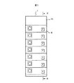
以下、最良の実施形態を添付図面を参照しながら説明する。図1,2,3は本実施形態にかかる配電盤を説明する図であり、図1は単位配電盤の正面図、図2は図1のA−A断面図、図3は図2のB−B断面図である。 Hereinafter, the best embodiment will be described with reference to the accompanying drawings. 1, 2 and 3 are diagrams for explaining the switchboard according to the present embodiment. FIG. 1 is a front view of the unit switchboard, FIG. 2 is a cross-sectional view taken along line AA in FIG. 1, and FIG. It is sectional drawing.
図において、1は単位配電盤、4は平板状の給電母線であり、前記単位配電盤1の筐体11の上部空間に水平に、例えば3本配置されている。5は接地母線であり、前記筐体の下部空間に水平に、例えば1本配置されている。6は配電盤ユニットであり、遮断器等の主回路機器7,継電器等の補助回路機器8を搭載する。9は外部接続電線であり、補助回路機器を外部保護回路等に接続する。10はケーブルであり、外部の負荷に接続されている。12はケーブルと主回路機器とを接続するための主回路端子台である。
In the figure, 1 is a unit switchboard, and 4 is a plate-shaped power supply bus. For example, three unit switchboards are horizontally arranged in the upper space of the
図1,2,3,に示すように、単位配電盤1の筐体11内には複数の配電盤ユニット6を搭載する。複数の配電盤ユニット6は、筐体11内に縦方向に搭載され、それぞれの配電盤ユニット6は、例えば、該配電盤ユニット6を介して、母線2とケーブル9を接続する。これにより、前記母線からの電力を前記制御ユニット6により制御して前記ケーブル10を介して外部に出力することができる。
As shown in FIGS. 1, 2, 3, a plurality of
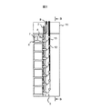
図4は、単位配電盤1a、1b、1cを列盤接続した例を説明する図(正面図)である。図4に示すように、単位配電盤1a、1b、1cを並べて配置する。このとき単位配電盤1a、1b、1cの型式が相互に異なると、単位配電盤1aの上部空間に配置した給電母線4a、単位配電盤1bの上部空間に配置した給電母線4b、および単位配電盤1cの上部空間に配置した給電母線4cの位置はそれぞれ異なり、これらは、一つの直線上に配置されない場合が生じる。
FIG. 4 is a diagram (front view) illustrating an example in which the
同様に、単位配電盤1aの下部空間に配置した接地母線5a、単位配電盤1bの下部空間に配置した接地母線5b、単位配電盤1cの下部空間に配置した接地母線5cの位置はそれぞれ異なり、これらは、一つの直線直線上に配置されない場合が生じる。
Similarly, the positions of the
図5は、上述のように、一つの直線上に配置されていない母線を接続するための接続導体を説明する図である。図5において、40は単位配電盤1aに収容された給電母線4aと単位配電盤1bに収容された給電母線4bとを接続する母線接続導体であり、前記母線4aの一端にその一端がろう付け等の手段により固着された平編銅ケーブル等からなる可撓性導体41、および前記可撓性導体の他端に取り付けられ、隣接する母線に締結するための貫通孔を具備した接続端子42を備えている。
FIG. 5 is a diagram for explaining the connection conductors for connecting the buses not arranged on one straight line as described above. In FIG. 5,
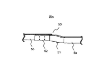
図6は、一つの直線上に配置されていない接地母線を接続する例を説明する図である。図6において、50は単位配電盤1aに収容された接地母線5aと単位配電盤1bに収容された接地母線5bとを接続する接地母線接続導体であり、前記母線5aの一端にその一端がろう付け等の手段により固着された平編み銅ケーブル等からなる可撓性導体51、および前記可撓性導体の他端に取り付けられ、隣接する母線に締結するための貫通孔を具備した接続端子52を備えている。
FIG. 6 is a diagram for explaining an example of connecting ground buses that are not arranged on one straight line. In FIG. 6,
以上説明したように、本実施形態によれば、隣接する単位配電盤に収容した給電母線4a、4b間あるいは接地母線5a、5b間、あるいは給電母線4a、4c間あるいは接地母線5a、5c間を可撓性を有する接続導体で接続するので、型式の異なる単位配電盤であっても容易に列盤を構成することができる。
As described above, according to the present embodiment, it is possible to connect between the
また、可撓性を有する導体として放熱性が良好な平編銅ケーブルを用いるので、ケーブルを過熱することなく大電流を流すことができる。また、本発明の接続方式によれば、隣接する配電盤間でその形式が異り、あるいは据え付け位置に偏差があり、接続する母線導体間での接続位置に偏差が生じていても、この偏差を可撓性導体部分で吸収して両導体を容易に接続することができる。 In addition, since a flat knitted copper cable with good heat dissipation is used as the flexible conductor, a large current can flow without overheating the cable. Further, according to the connection method of the present invention, even if the type is different between adjacent switchboards or there is a deviation in the installation position, even if there is a deviation in the connection position between the connected bus conductors, this deviation is reduced. Both conductors can be easily connected by being absorbed by the flexible conductor portion.
1 単位配電盤
4 給電母線
5 接地母線
6 配電盤ユニット
7 主回路機器
8 補助回路機器
9 外部電線
10 ケーブル
12 主回路端子台
40 母線接続導体
50 接地母線接続導体
1
Claims (1)
単位配電盤の複数個を、該単位配電盤内に配置した前記給電母線および接地母線のそれぞれを一直線状に揃えて列状に配置し結合して列盤接続する配電盤において、
列盤接続される単位配電盤内に配置した母線の少なくとも一端には、隣接する単位配電盤内に配置した母線との相対位置のずれを吸収して両者を電気的に接続するための可撓性の平編銅ケーブルの一端を予め接続してなることを特徴とする配電盤。 A plurality of control units each incorporating a main circuit device including a circuit breaker and an auxiliary circuit device including a relay, a power supply bus, a ground bus, and an output cable are provided, and power from the power supply bus is controlled by the control unit. A plurality of unit switchboards that output to the outside via the cable,
In the switchboard in which a plurality of unit switchboards are arranged in a line in a straight line with each of the power supply buses and the ground busbars arranged in the unit switchboard and connected in a row ,
At least one end of the bus arranged in the unit switchboard connected to the row is absorbed in a relative position with respect to the bus arranged in the adjacent unit switchboard and electrically connected to each other. A switchboard characterized by connecting one end of a flat knitted copper cable in advance.
Priority Applications (1)
| Application Number | Priority Date | Filing Date | Title |
|---|---|---|---|
| JP2009047995A JP5081853B2 (en) | 2009-03-02 | 2009-03-02 | switchboard |
Applications Claiming Priority (1)
| Application Number | Priority Date | Filing Date | Title |
|---|---|---|---|
| JP2009047995A JP5081853B2 (en) | 2009-03-02 | 2009-03-02 | switchboard |
Publications (2)
| Publication Number | Publication Date |
|---|---|
| JP2010206894A JP2010206894A (en) | 2010-09-16 |
| JP5081853B2 true JP5081853B2 (en) | 2012-11-28 |
Family
ID=42967818
Family Applications (1)
| Application Number | Title | Priority Date | Filing Date |
|---|---|---|---|
| JP2009047995A Expired - Fee Related JP5081853B2 (en) | 2009-03-02 | 2009-03-02 | switchboard |
Country Status (1)
| Country | Link |
|---|---|
| JP (1) | JP5081853B2 (en) |
Families Citing this family (3)
| Publication number | Priority date | Publication date | Assignee | Title |
|---|---|---|---|---|
| JP2013027067A (en) * | 2011-07-15 | 2013-02-04 | Fuji Electric Co Ltd | Power feed connection structure of electric power conversion system |
| EP3270477B1 (en) * | 2015-03-13 | 2021-10-13 | Mitsubishi Electric Corporation | Electric apparatus |
| KR20190041660A (en) * | 2017-10-13 | 2019-04-23 | 코스탈 주식회사 | A sub bus-bar for cabinet panel |
Family Cites Families (4)
| Publication number | Priority date | Publication date | Assignee | Title |
|---|---|---|---|---|
| JPS6018610U (en) * | 1983-07-14 | 1985-02-08 | 株式会社明電舎 | switchboard |
| JP2002151178A (en) * | 2000-11-16 | 2002-05-24 | Toshiba Corp | Grounding device of electric apparatus |
| JP2005057831A (en) * | 2003-08-05 | 2005-03-03 | Japan Ae Power Systems Corp | Gas insulated opening and closing device |
| JP2008131717A (en) * | 2006-11-20 | 2008-06-05 | Hitachi Ltd | Control center |
-
2009
- 2009-03-02 JP JP2009047995A patent/JP5081853B2/en not_active Expired - Fee Related
Also Published As
| Publication number | Publication date |
|---|---|
| JP2010206894A (en) | 2010-09-16 |
Similar Documents
| Publication | Publication Date | Title |
|---|---|---|
| KR101286812B1 (en) | Switch gear | |
| US8547684B2 (en) | Panelboard having a parallel feeder bars distribution | |
| RU2398322C1 (en) | Supply bus system | |
| JP5484638B2 (en) | Gas insulated switchgear | |
| KR100984143B1 (en) | Multiple conductor connection apparatus and power distributor using the same | |
| JP4046688B2 (en) | Power distributor and control center | |
| KR101176626B1 (en) | Compact cabiinet panel | |
| US9615470B2 (en) | Wiring combiner box | |
| JP5081853B2 (en) | switchboard | |
| JP2012182963A (en) | Bar holder for switchboard | |
| JP2006238562A (en) | Plug-in distribution board | |
| JP2010029018A (en) | Closed switchboard | |
| JP4979481B2 (en) | Bar holder for distribution board | |
| JP4625385B2 (en) | switchboard | |
| CN109950795B (en) | Current distribution device in an electrical panel or electrical switchgear | |
| JPWO2015182009A1 (en) | Busbar structure and switchboard using the same | |
| JP4958282B2 (en) | Breaker unit | |
| EP3731356B1 (en) | Gas-insulated open/close device | |
| JP7154702B2 (en) | switchboard | |
| JP7382891B2 (en) | DC switchboard | |
| JP6433336B2 (en) | Distribution board | |
| EP3270477B1 (en) | Electric apparatus | |
| JP6143525B2 (en) | Power distribution facilities | |
| KR101623761B1 (en) | Clip assembly and distribution board including the same | |
| KR200449732Y1 (en) | Assembly Plug for the Cabinet Panel |
Legal Events
| Date | Code | Title | Description |
|---|---|---|---|
| A621 | Written request for application examination |
Free format text: JAPANESE INTERMEDIATE CODE: A621 Effective date: 20101209 |
|
| A977 | Report on retrieval |
Free format text: JAPANESE INTERMEDIATE CODE: A971007 Effective date: 20120608 |
|
| A131 | Notification of reasons for refusal |
Free format text: JAPANESE INTERMEDIATE CODE: A131 Effective date: 20120612 |
|
| A521 | Written amendment |
Free format text: JAPANESE INTERMEDIATE CODE: A523 Effective date: 20120806 |
|
| TRDD | Decision of grant or rejection written | ||
| A01 | Written decision to grant a patent or to grant a registration (utility model) |
Free format text: JAPANESE INTERMEDIATE CODE: A01 Effective date: 20120821 |
|
| A01 | Written decision to grant a patent or to grant a registration (utility model) |
Free format text: JAPANESE INTERMEDIATE CODE: A01 |
|
| A61 | First payment of annual fees (during grant procedure) |
Free format text: JAPANESE INTERMEDIATE CODE: A61 Effective date: 20120903 |
|
| FPAY | Renewal fee payment (event date is renewal date of database) |
Free format text: PAYMENT UNTIL: 20150907 Year of fee payment: 3 |
|
| R150 | Certificate of patent or registration of utility model |
Free format text: JAPANESE INTERMEDIATE CODE: R150 |
|
| LAPS | Cancellation because of no payment of annual fees |