JP5076552B2 - Vehicle control device - Google Patents
Vehicle control device Download PDFInfo
- Publication number
- JP5076552B2 JP5076552B2 JP2007050862A JP2007050862A JP5076552B2 JP 5076552 B2 JP5076552 B2 JP 5076552B2 JP 2007050862 A JP2007050862 A JP 2007050862A JP 2007050862 A JP2007050862 A JP 2007050862A JP 5076552 B2 JP5076552 B2 JP 5076552B2
- Authority
- JP
- Japan
- Prior art keywords
- wheel
- camber angle
- camber
- tread
- vehicle
- Prior art date
- Legal status (The legal status is an assumption and is not a legal conclusion. Google has not performed a legal analysis and makes no representation as to the accuracy of the status listed.)
- Expired - Fee Related
Links
Images


Landscapes
- Steering-Linkage Mechanisms And Four-Wheel Steering (AREA)
- Steering Control In Accordance With Driving Conditions (AREA)
- Vehicle Body Suspensions (AREA)
Description
本発明は、車輪と、その車輪のキャンバー角を調整するキャンバー角調整装置とを有する車両に対し、キャンバー角調整装置を作動させて、車輪のキャンバー角を制御する車両用制御装置に関し、特に、高グリップ性と低燃費との両立を図ることができる車両用制御装置に関するものである。 The present invention relates to a vehicle control device that controls a camber angle of a wheel by operating the camber angle adjustment device for a vehicle having a wheel and a camber angle adjustment device that adjusts the camber angle of the wheel. The present invention relates to a vehicle control device capable of achieving both high grip performance and low fuel consumption.
車輪のキャンバー角(タイヤ中心と地面とがなす角度)をマイナス方向で大きくとることで、タイヤの能力を十分に引き出して、旋回性能の向上を図る試みが行われている。これは、キャンバー角を例えば0°に設定していると、直進走行時にはトレッドが幅方向の全域で地面に接地するが、旋回時には遠心力による車両のロールにより内側のトレッドが地面から浮き上がり、十分な旋回性能を得られないからである。従って、マイナス方向のキャンバー角を予め付与しておくことで、旋回時にトレッドが地面へ幅広く接地でき、旋回性能の向上を図ることができる。 Attempts have been made to improve the turning performance by taking out the tire capacity sufficiently by increasing the camber angle of the wheel (the angle formed by the tire center and the ground) in the minus direction. For example, if the camber angle is set to 0 °, for example, the tread touches the ground in the entire width direction when traveling straight, but the inner tread floats off the ground due to the roll of the vehicle due to centrifugal force when turning. This is because the turning performance cannot be obtained. Therefore, by assigning a negative camber angle in advance, the tread can come into contact with the ground widely during turning, and the turning performance can be improved.
しかしながら、マイナス方向に大きなキャンバー角で車輪を車両に装着すると、タイヤの旋回性能は向上されるが、直進走行時に内側のトレッド端部における接地圧が高くなり、タイヤが偏磨耗して不経済であると共に、トレッド端部の温度が高温になるという問題点があった。 However, if the wheel is attached to the vehicle with a large camber angle in the negative direction, the turning performance of the tire is improved, but the ground contact pressure at the inner tread edge increases during straight running, and the tire is unevenly worn, which is uneconomical. In addition, there is a problem that the temperature of the tread edge becomes high.
そこで、特開平2−185802号公報には、マイナス方向に大きなキャンバー角で車両に車輪を装着する場合に、タイヤの一方側のサイド部を他方側のサイド部より強く補強して剛性を大ならしめると共に、トレッドゴムを2分して、その一方側を他方側より硬度を低くする、或いはトレッド端部のトレッド厚みを厚くして、耐摩耗性、耐熱性及び高グリップ性を確保する技術が開示されている(特許文献1)。 Therefore, in Japanese Patent Laid-Open No. 2-185802, when mounting a wheel on a vehicle with a large camber angle in the minus direction, the side portion on one side of the tire is reinforced stronger than the side portion on the other side to increase rigidity. A technology that secures wear resistance, heat resistance and high grip by halving the tread rubber and making one side lower in hardness than the other side, or increasing the tread end thickness. (Patent Document 1).
また、US6,347,802B1公報には、車輪のキャンバー角をアクチュエータの駆動力によってアクティブ制御するサスペンションシステムが開示されている(特許文献2)。
しかしながら、前者の技術では、旋回時の高グリップ性を維持するという点では十分な性能を発揮し得るが、高グリップ性と低燃費(低転がり抵抗)との両立という点では不十分であるという問題点があった。また、上述した従来の技術では、高グリップ性は旋回時に限られるものであり、例えば、直進走行時の急加速・急制動時における高グリップ性の発揮が不十分であるという問題点があった。同様に、後者の技術では、高グリップ性と低燃費との両立という点では不十分であるという問題点があった。 However, the former technique can demonstrate sufficient performance in terms of maintaining high grip when turning, but is insufficient in terms of both high grip and low fuel consumption (low rolling resistance). There was a problem. Further, in the above-described conventional technology, the high grip performance is limited at the time of turning. For example, there is a problem that the high grip performance at the time of rapid acceleration / braking during straight running is insufficient. . Similarly, the latter technique has a problem that it is insufficient in terms of achieving both high grip performance and low fuel consumption.
本発明は上述した問題点を解決するためになされたものであり、高グリップ性と低燃費との両立を図ることができる車両用制御装置を提供することを目的としている。 The present invention has been made to solve the above-described problems, and an object of the present invention is to provide a vehicle control device capable of achieving both high grip performance and low fuel consumption.
この目的を解決するために請求項1記載の車両用制御装置は、幅方向に並設された少なくとも第1トレッドと第2トレッドとを備えると共に、前記第1トレッドは前記第2トレッドに比してグリップ力の高い特性に構成されると共に、前記第2トレッドは前記第1トレッドに比して転がり抵抗の小さい特性に構成された車輪と、その車輪のキャンバー角を調整するキャンバー角調整装置と、を備える車両に対し、前記キャンバー角調整装置を作動させて、前記車輪のキャンバー角を制御するものであって、前記車輪がスリップしているか否かを判断するスリップ判断手段と、車両の対地速度と前記車輪の回転速度とから、前記車輪のスリップ比を算出するスリップ比算出手段と、そのスリップ判断手段により前記車輪がスリップしていると判断された場合に、前記スリップ比算出手段により算出されたスリップ比が大きくなるほど前記車輪のキャンバー角を大きくして、前記車輪の前記第2トレッドに比べて前記第1トレッドの接地を多くするように、前記キャンバー角調整装置を作動させて前記車輪のキャンバー角を変更するキャンバー角変更手段と、を備える。
In order to solve this object, the vehicle control device according to
請求項2記載の車両用制御装置は、請求項1記載の車両用制御装置において、前記車輪を複数備えると共に、前記キャンバー角調整装置が前記複数の車輪のキャンバー角をそれぞれ独立に調整可能に構成され、前記スリップ判断手段により前記車輪がスリップしていると判断された場合に、前記複数の車輪の中からスリップしている車輪を特定する車輪特定手段と、を備え、前記キャンバー角変更手段は、前記車輪特定手段により特定された車輪のキャンバー角を変更する。
The vehicle control device according to
請求項3記載の車両用制御装置は、請求項1又は2に記載の車両用制御装置において、前記キャンバー角変更手段は、前記スリップ比算出手段により算出されたスリップ比が所定のスリップ比よりも大きい場合に、前記車輪のキャンバー角を変更する。
3. The vehicle control apparatus described, in the vehicle control system according to
請求項4記載の車両用制御装置は、請求項1から3のいずれかに記載の車両用制御装置において、前記車輪に回転駆動力を付与する車輪駆動装置の駆動状態を制御する駆動力制御手段と、前記キャンバー角変更手段により変更する前記車輪のキャンバー角が、前記キャンバー角調整装置により調整可能な範囲を超えるか否かを判断するキャンバー角判断手段と、を備え、前記駆動力制御手段による前記車輪駆動装置の制御は、前記キャンバー角判断手段により、調整可能な範囲を超えると判断された場合に行われる。
The vehicle control device according to
請求項1記載の車両用制御装置によれば、キャンバー角調整装置によって車輪のキャンバー角がマイナス方向(ネガティブキャンバー方向)に調整されると、車両の内側に配置されるトレッド(第1トレッド又は第2トレッド)の接地圧が増加される一方、車両の外側に配置されるトレッド(第2トレッド又は第1トレッド)の接地圧が減少される。 According to the vehicle control device of the first aspect, when the camber angle of the wheel is adjusted in the minus direction (negative camber direction) by the camber angle adjusting device, the tread (the first tread or the first tread disposed inside the vehicle) is adjusted. While the contact pressure of 2 treads is increased, the contact pressure of the tread (second tread or first tread) disposed outside the vehicle is decreased.
これに対し、車輪のキャンバー角がプラス方向(ポジティブキャンバー方向)に調整されると、車両の内側に配置されるトレッド(第1トレッド又は第2トレッド)の接地圧が減少される一方、車両の外側に配置されるトレッド(第2トレッド又は第1トレッド)の接地圧が増加される。 On the other hand, when the camber angle of the wheel is adjusted in the positive direction (positive camber direction), the ground pressure of the tread (first tread or second tread) disposed inside the vehicle is reduced, while the vehicle The contact pressure of the tread (second tread or first tread) arranged on the outside is increased.
このように、本発明の車両用制御装置によれば、キャンバー角調整装置によって車輪のキャンバー角を調整することで、車輪の第1トレッドにおける接地圧と第2トレッドにおける接地圧との比率(一方のトレッドのみが接地し、他方のトレッドが路面から離れている状態を含む)を任意のタイミングで変更することができるので、第1トレッドの特性より得られる性能と第2トレッドの特性より得られる性能との2つの性能の両立を図ることができるという効果がある。 Thus, according to the vehicle control device of the present invention, the ratio of the ground pressure in the first tread and the ground pressure in the second tread of the wheel (one side) is adjusted by adjusting the camber angle of the wheel by the camber angle adjusting device. (Including the state in which only one tread is grounded and the other tread is away from the road surface) can be changed at an arbitrary timing, so that the performance obtained from the characteristics of the first tread and the characteristics of the second tread can be obtained. There is an effect that it is possible to achieve both performance and performance.
ここで、本発明の車両用制御装置によれば、第1トレッドを、第2トレッドに比して、グリップ力の高い特性とすると共に、第2トレッドを、第1トレッドに比して、転がり抵抗の小さい特性とする構成であるので、車輪のキャンバー角を調整して、第1トレッドにおける接地圧と第2トレッドにおける接地圧との比率(一方のトレッドのみが接地し、他方のトレッドが路面から離れている状態を含む)を変更することで、走行性能(例えば、旋回性能、加速性能、制動性能或いは雨天時や積雪路などでの車両安定性など)と省燃費性能との2つの性能の両立を図ることができるという効果がある。 Here, according to the vehicle control device of the present invention, the first tread has a higher gripping property than the second tread, and the second tread rolls compared to the first tread. Since the structure has low resistance, the camber angle of the wheel is adjusted, and the ratio between the ground pressure in the first tread and the ground pressure in the second tread (only one tread is grounded and the other tread is the road surface) 2 performances, including driving performance (for example, turning performance, acceleration performance, braking performance or vehicle stability on rainy or snowy roads) and fuel saving performance. There is an effect that both can be achieved.
このように互いに背反する2つの性能の両立は、従来の車両では達成することが不可能であり、それぞれの性能に対応する2種類のタイヤを履き替える必要があったところ、本発明のように、第1及び第2トレッドを有する車輪のキャンバー角が、作動制御手段によるキャンバー角調整装置の作動状態の制御により調整される構成とすることで初めて達成可能となったものであり、これにより、互いに背反する2つの性能の両立を達成することができる。 Thus, the coexistence of two contradicting performances cannot be achieved by a conventional vehicle, and two types of tires corresponding to the respective performances must be replaced. The camber angle of the wheel having the first and second treads can be achieved for the first time by adjusting the operation state of the camber angle adjusting device by the operation control means. It is possible to achieve a balance between two performances that are contradictory to each other.
また、本発明の車両用制御装置によれば、車輪がスリップしているか否かをスリップ判断手段によって判断すると共に、そのスリップ判断手段により車輪がスリップしていると判断した場合に、車輪の第2トレッドに比べて第1トレッドの接地を多くするように、キャンバー角変更手段によってキャンバー角調整装置を作動させて車輪のキャンバー角を変更する構成であるので、第1トレッドの高グリップ性を利用して車輪のグリップ力を回復させることができる。これにより、車輪のスリップを防止することができ、車両の走行安定性を確保することができるという効果がある。また、車輪のスリップを防止することができれば、その分、省燃費性能の向上を図ることができるという効果がある。 Further, according to the vehicle control device of the present invention, when the slip determining means determines whether or not the wheel is slipping, and when the slip determining means determines that the wheel is slipping, The camber angle adjustment device is operated by the camber angle changing means to change the camber angle of the wheel so that the ground contact of the first tread is increased compared to the 2 tread, so the high grip property of the first tread is used. Thus, the grip force of the wheel can be recovered. Thereby, it is possible to prevent the wheels from slipping and to ensure the running stability of the vehicle. Further, if the slipping of the wheel can be prevented, the fuel saving performance can be improved accordingly.
ここで、車輪がスリップしている場合には、車輪のグリップ力が小さい状態にあるということなので、その状態のまま走行したのでは、車両の走行安定性が低下する。一方、車輪がスリップしていない場合には、車輪のグリップ力が大きい状態にあるということなので、車輪のキャンバー角を変更しなくとも、車両の走行安定性を確保することができる。そこで、本発明の車両用制御装置のように、車輪がスリップしていると判断された場合に車輪のキャンバー角を変更する構成とすることで、車両の走行安定性を確保しつつも、車輪がスリップしていない場合には、第2トレッドの低転がり性を利用して省燃費性能の向上を図ることができるという効果がある。
また、車輪のスリップ比をスリップ比算出手段によって算出すると共に、そのスリップ比算出手段により算出したスリップ比が大きくなるほど車輪のキャンバー角を大きくする構成であるので、スリップしている車輪のグリップ力を適切に回復させることができるという効果がある。
例えば、スリップ比が大きい場合には、車輪のグリップ力を大きく回復させる必要があるという知見に基づき、スリップ比が大きくなるほど、車輪のグリップ力が大きくなるようにキャンバー角を規定することで、グリップ力の回復効果をより大きく発揮させることができるという効果がある。その結果、より一層の車両の走行安定性を確保することができるという効果がある。
なお、スリップ比算出手段により算出するスリップ比とは、車輪の自由回転時(車輪がスリップしていない状態で転動していると仮定した場合)における回転数と車輪の実際の回転数との違い、或いは、車輪の自由回転時における周速度と車輪の実際の周速度との違い等を意味しており、車輪の自由回転時における回転数または周速度と、車輪の実際の回転数または周速度との比率のみでなく、例えば、車輪の自由回転時における回転数または周速度と、車輪の実際の回転数または周速度との差などを含む趣旨である。
Here, when the wheel is slipping, it means that the grip force of the wheel is in a small state. Therefore, if the vehicle travels in that state, the traveling stability of the vehicle is lowered. On the other hand, when the wheel is not slipping, it means that the grip force of the wheel is in a large state, so that the running stability of the vehicle can be ensured without changing the camber angle of the wheel. Thus, as in the vehicle control device of the present invention, the wheel camber angle is changed when it is determined that the wheel is slipping. When there is no slip, there is an effect that the fuel saving performance can be improved by utilizing the low rolling property of the second tread.
Further, the wheel slip ratio is calculated by the slip ratio calculating means, and the camber angle of the wheel is increased as the slip ratio calculated by the slip ratio calculating means is increased. The effect is that it can be properly recovered.
For example, if the slip ratio is large, the gripping force of the wheel needs to be greatly recovered. Based on the knowledge that the grip ratio of the wheel increases as the slip ratio increases, There is an effect that the power recovery effect can be exhibited more greatly. As a result, there is an effect that further traveling stability of the vehicle can be ensured.
Note that the slip ratio calculated by the slip ratio calculating means is the difference between the rotational speed at the time of free rotation of the wheel (assuming that the wheel is rolling without slipping) and the actual rotational speed of the wheel. It means the difference or the difference between the peripheral speed at the free rotation of the wheel and the actual peripheral speed of the wheel, and the rotation speed or peripheral speed at the free rotation of the wheel and the actual rotation speed or peripheral of the wheel. In addition to the ratio to the speed, for example, it includes the difference between the rotational speed or the peripheral speed during free rotation of the wheel and the actual rotational speed or peripheral speed of the wheel.
請求項2記載の車両用制御装置によれば、請求項1記載の車両用制御装置の奏する効果に加え、車輪を複数備えると共に、キャンバー角調整装置が複数の車輪のキャンバー角をそれぞれ独立に調整可能に構成され、スリップ判断手段により車輪がスリップしていると判断した場合に、複数の車輪の中からスリップしていると判断した車輪を車輪特定手段によって特定すると共に、その車輪特定手段により特定した車輪のキャンバー角を変更する構成であるので、スリップしている車輪のグリップ力を適切に回復させることができるという効果がある。 According to the vehicle control device of the second aspect, in addition to the effect produced by the vehicle control device of the first aspect, the vehicle control device includes a plurality of wheels, and the camber angle adjusting device independently adjusts the camber angles of the plurality of wheels. When it is determined that the wheel is slipping by the slip determination means, the wheel determined to be slipping from among the plurality of wheels is specified by the wheel specifying means, and specified by the wheel specifying means. Since the camber angle of the wheel is changed, the gripping force of the slipping wheel can be recovered properly.
また、通常、車輪がスリップしている場合には、各車輪のグリップ力は車輪毎にそれぞれ異なるグリップ力となっているので、スリップしている車輪のグリップ力を適切に回復させることができれば、より一層の車両の走行安定性を確保することができるという効果がある。 Also, normally, when the wheel is slipping, the grip force of each wheel is different for each wheel, so if the grip force of the slipping wheel can be properly recovered, There is an effect that it is possible to secure further running stability of the vehicle.
更に、本発明の車両用制御装置によれば、車輪がスリップしていると、複数の車輪の中からスリップしている車輪のキャンバー角を変更する構成であるので、スリップしていない車輪は第2トレッドの低転がり性を利用して省燃費性能の向上を図ることができるという効果がある。 Further, according to the vehicle control device of the present invention, when the wheel is slipping, the camber angle of the slipping wheel is changed from among the plurality of wheels. There is an effect that fuel saving performance can be improved by utilizing the low rolling property of 2 treads.
その結果、路面と車輪の接地面との間の摩擦係数が左右輪で異なる路面(例えば、スプリット路)を走行する場合においても、車両の走行安定性の確保と省燃費性能の向上との両立を達成することができるという効果がある。 As a result, even when driving on road surfaces (for example, split roads) where the friction coefficient between the road surface and the ground contact surface of the wheels differs between the left and right wheels, ensuring both vehicle stability and improving fuel efficiency There is an effect that can be achieved.
請求項3記載の車両用制御装置によれば、請求項1又は2に記載の車両用制御装置の奏する効果に加え、スリップ比算出手段により算出したスリップ比が所定のスリップ比よりも大きい場合に、車輪のキャンバー角を変更する構成であるので、スリップしている車輪のグリップ力を効率的に回復させることができるという効果がある。 According to the vehicle control device of the third aspect, in addition to the effect produced by the vehicle control device according to the first or second aspect, when the slip ratio calculated by the slip ratio calculation means is larger than a predetermined slip ratio. Since the camber angle of the wheel is changed, the gripping force of the slipping wheel can be efficiently recovered.
また、本発明の車両用制御装置によれば、スリップ比が所定のスリップ比よりも小さい場合には、車輪のキャンバー角を変更する必要がなく、その分、処理を簡素化することができるので、制御装置の制御負荷を軽減することができるという効果がある。 Moreover, according to the vehicle control device of the present invention, when the slip ratio is smaller than the predetermined slip ratio, it is not necessary to change the camber angle of the wheel, and the processing can be simplified correspondingly. There is an effect that the control load of the control device can be reduced.
請求項4記載の車両用制御装置によれば、請求項1から3のいずれかに記載の車両用制御装置の奏する効果に加え、キャンバー角変更手段により変更する車輪のキャンバー角が、キャンバー角調整装置により調整可能な範囲を超えるか否かをキャンバー角判断手段によって判断すると共に、そのキャンバー角判断手段により、調整可能な範囲を超えると判断した場合に、駆動力制御手段による車輪駆動装置の駆動状態の制御が行われる構成であるので、例えば、車輪に付与する回転駆動力が低下するように車輪駆動装置の駆動状態を制御することで、車輪のキャンバー角が変更できない場合であっても、車輪の回転駆動力の低下を利用して車輪のグリップ力を回復させることができる。これにより、車輪のスリップを防止することができ、車両の走行安定性を確保することができるという効果がある。 According to the vehicle control device of the fourth aspect , in addition to the effect exhibited by the vehicle control device according to any one of the first to third aspects, the camber angle of the wheel changed by the camber angle changing means is adjusted by the camber angle adjustment. The camber angle determining means determines whether or not the range adjustable by the device is exceeded, and when the camber angle determining means determines that the adjustable range is exceeded, the driving force control means drives the wheel drive device. Since the control of the state is performed, for example, by controlling the driving state of the wheel driving device so that the rotational driving force applied to the wheel is reduced, even if the camber angle of the wheel cannot be changed, The grip force of the wheel can be recovered by utilizing the decrease in the rotational driving force of the wheel. Thereby, it is possible to prevent the wheels from slipping and to ensure the running stability of the vehicle.
即ち、キャンバー角調整装置により調整可能なキャンバー角には限度があり、調整目標とするキャンバー角が限度を超える場合には、調整可能な範囲内でキャンバー角を調整しなければならず、車輪のグリップ力を十分に回復させることができない。 In other words, there is a limit to the camber angle that can be adjusted by the camber angle adjusting device. When the camber angle targeted for adjustment exceeds the limit, the camber angle must be adjusted within the adjustable range. The grip force cannot be fully recovered.
これに対し、本発明の車両用制御装置によれば、調整目標となるキャンバー角が限度を超える場合には、車輪のグリップ力を大きく回復させる必要があるという知見に基づき、車輪の回転駆動力が低下するように車輪駆動装置の駆動状態を制御することで、車輪の回転駆動力の低下を利用して車輪のグリップ力を回復させることができる。その結果、車両の走行安定性を確保することができる。 On the other hand, according to the vehicle control device of the present invention, when the camber angle that is the adjustment target exceeds the limit, the rotational driving force of the wheel is based on the knowledge that the gripping force of the wheel needs to be largely recovered. By controlling the driving state of the wheel driving device so as to decrease, it is possible to recover the grip force of the wheel by utilizing the decrease in the rotational driving force of the wheel. As a result, the running stability of the vehicle can be ensured.
また、車輪のスリップを防止することができれば、その分、省燃費性能の向上を図ることができるという効果がある。 Further, if the slipping of the wheel can be prevented, the fuel saving performance can be improved accordingly.
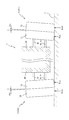
以下、本発明の好ましい実施の形態について添付図面を参照して説明する。図1は、本発明の第1実施の形態における車両用制御装置100が搭載される車両1を模式的に示した模式図である。なお、図1の矢印FWDは、車両1の前進方向を示す。
Hereinafter, preferred embodiments of the present invention will be described with reference to the accompanying drawings. FIG. 1 is a schematic diagram schematically showing a
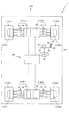
まず、車両1の概略構成について説明する。車両1は、図1に示すように、車体フレームBFと、その車体フレームBFに支持される複数(本実施の形態では4輪)の車輪2と、それら各車輪2を独立に回転駆動する車輪駆動装置3と、各車輪2の操舵駆動及びキャンバー角の調整等を行うキャンバー角調整装置4とを主に備え、車輪2のキャンバー角を車両用制御装置100により制御して、車輪2に設けられた2種類のトレッドを使い分けることで(図5及び図6参照)、走行性能の向上と省燃費の達成とを図ることができるように構成されている。
First, a schematic configuration of the
次いで、各部の詳細構成について説明する。車輪2は、図1に示すように、車両1の進行方向前方側に位置する左右の前輪2FL,2FRと、進行方向後方側に位置する左右の後輪2RL,2RRとの4輪を備え、これら前後輪2FL〜2RRは、車輪駆動装置3から回転駆動力を付与されて、それぞれ独立に回転可能に構成されている。
Next, the detailed configuration of each part will be described. As shown in FIG. 1, the
車輪駆動装置3は、各車輪2を独立に回転駆動するための回転駆動装置であり、図1に示すように、4個の電動モータ(FL〜RRモータ3FL〜3RR)を各車輪2に(即ち、インホイールモータとして)配設して構成されている。運転者がアクセルペダル52を操作した場合には、各車輪駆動装置3から回転駆動力が各車輪2に付与され、各車輪2がアクセルペダル52の操作量に応じた回転速度で回転される。
The
また、車輪2(前後輪2FL〜2RR)は、キャンバー角調整装置4により舵角とキャンバー角とが調整可能に構成されている。キャンバー角調整装置4は、各車輪2の舵角とキャンバー角とを調整するための駆動装置であり、図1に示すように、各車輪2に対応する位置に合計4個(FL〜RRアクチュエータ4FL〜4RR)が配置されている。
The wheels 2 (front and rear wheels 2FL to 2RR) are configured such that the steering angle and the camber angle can be adjusted by the camber
例えば、運転者がステアリング54を操作した場合には、キャンバー角調整装置4の一部(例えば、前輪2FL,2FR側のみ)又は全部が駆動され、ステアリング54の操作量に応じた舵角を車輪2に付与する。これにより、車輪2の操舵動作が行われ、車両1が所定の方向へ旋回される。
For example, when the driver operates the
また、キャンバー角調整装置4は、車両1の走行状態(例えば、定速走行時または加減速時、或いは、直進時または旋回時)や車輪2が走行する路面Gの状態(例えば、乾燥路面時と雨天路面時)などの状態変化に応じて、車両用制御装置100により作動制御され、車輪2のキャンバー角を調整する。
Further, the camber
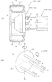
ここで、図2を参照して、車輪駆動装置3とキャンバー角調整装置4との詳細構成について説明する。図2(a)は、車輪2の断面図であり、図2(b)は、車輪2の舵角及びキャンバー角の調整方法を模式的に説明する模式図である。
Here, with reference to FIG. 2, the detailed structure of the
なお、図2(a)では、車輪駆動装置3に駆動電圧を供給するための電源配線などの図示が省略されている。また、図2(b)中の仮想軸Xf−Xb、仮想軸Yl−Yr、及び、仮想軸Zu−Zdは、それぞれ車両1の前後方向、左右方向、及び、上下方向にそれぞれ対応する。
In FIG. 2A, illustration of power supply wiring for supplying a drive voltage to the
図2(a)に示すように、車輪2(前後輪2FL〜2RR)は、ゴム状弾性材から構成されるタイヤ2aと、アルミニウム合金などから構成されるホイール2bとを主に備えて構成され、ホイール2bの内周部には、車輪駆動装置3(FL〜RRモータ3FL〜3RR)がインホイールモータとして配設されている。
As shown in FIG. 2 (a), the wheel 2 (front and rear wheels 2FL to 2RR) mainly includes a
タイヤ2aは、車両1の内側(図2(a)右側)に配置される第1トレッド21と、その第1トレッド21と特性が異なり、車両1の外側(図2(a)左側)に配置される第2トレッド22とを備える。なお、車輪2(タイヤ2a)の詳細構成については図4を参照して後述する。
The
車輪駆動装置3は、図2(a)に示すように、その前面側(図2(a)左側)に突出された駆動軸3aがホイール2bに連結固定されており、駆動軸3aを介して、回転駆動力を車輪2へ伝達可能に構成されている。また、車輪駆動装置3の背面には、キャンバー角調整装置4(FL〜RRアクチュエータ4FL〜4RR)が連結固定されている。
As shown in FIG. 2 (a), the
キャンバー角調整装置4は、複数本(本実施の形態では3本)の油圧シリンダ4a〜4cを備えており、それら3本の油圧シリンダ4a〜4cのロッド部は、車輪駆動装置3の背面側(図2(a)右側)にジョイント部(本実施の形態ではユニバーサルジョイント)54を介して連結固定されている。なお、図2(b)に示すように、各油圧シリンダ4a〜4cは、周方向略等間隔(即ち、周方向120°間隔)に配置されると共に、1の油圧シリンダ4bは、仮想軸Zu−Zd上に配置されている。
The camber
これにより、各油圧シリンダ4a〜4cが各ロッド部をそれぞれ所定方向に所定長さだけ伸長駆動又は収縮駆動することで、車輪駆動装置3が仮想軸Xf−Xb,Zu−Xdを揺動中心として揺動駆動され、その結果、各車輪2に所定のキャンバー角と舵角とが付与される。
As a result, each
例えば、図2(b)に示すように、車輪2が中立位置(車両1の直進状態)にある状態で、油圧シリンダ4bのロッド部が収縮駆動され、かつ、油圧シリンダ4a,4cのロッド部が伸長駆動されると、車輪駆動装置3が仮想線Xf−Xb回りに回転され(図2(b)矢印A)、車輪2にマイナス方向(ネガティブキャンバー)のキャンバー角(車輪2の中心線が仮想線Zu−Zdに対してなす角度)が付与される。一方、これとは逆の方向に油圧シリンダ4b及び油圧シリンダ4a,4cがそれぞれ伸縮駆動されると、車輪2にプラス方向(ポジティブキャンバー)のキャンバー角が付与される。
For example, as shown in FIG. 2B, the rod portion of the
また、車輪2が中立位置(車両1の直進状態)にある状態で、油圧シリンダ4aのロッド部が収縮駆動され、かつ、油圧シリンダ4cのロッド部が伸長駆動されると、車輪駆動装置3が仮想線Zu−Zd回りに回転され(図2(b)矢印B)、車輪2にトーイン傾向の舵角(車輪2の中心線が車両1の基準線に対してなす角度であり、車両1の進行方向とは無関係に定まる角度)が付与される。一方、これとは逆の方向に油圧シリンダ4a及び油圧シリンダ4cが伸縮駆動されると、車輪2にトーアウト傾向の舵角が付与される。
Further, when the
なお、ここで例示した各油圧シリンダ4a〜4cの駆動方法は、上述した通り、車輪2が中立位置にある状態から駆動する場合を説明するものであるが、これらの駆動方法を組み合わせて各油圧シリンダ4a〜4cの伸縮駆動を制御することにより、車輪2に任意のキャンバー角及び舵角を付与することができる。
In addition, although the drive method of each
図1に戻って説明する。アクセルペダル52及びブレーキペダル53は、運転者により操作される操作部材であり、各ペダル52,53の踏み込み状態(踏み込み量、踏み込み速度など)に応じて、車両1の走行速度や制動力が決定され、車輪駆動装置3の作動制御が行われる。
Returning to FIG. The
ステアリング54は、運転者により操作される操作部材であり、その操作状態(回転角度、回転速度など)に応じて、車両1の旋回半径などが決定され、キャンバー角調整装置4の作動制御が行われる。ワイパースイッチ55は、運転者により操作される操作部材であり、その操作状態(操作位置など)に応じて、ワイパー(図示せず)の作動制御が行われる。
The steering 54 is an operation member operated by the driver, and the turning radius of the
同様に、ウインカスイッチ56及び高グリップスイッチ57は、運転者により操作される操作部材であり、その操作状態(操作位置など)に応じて、前者の場合はウインカー(図示せず)の作動制御が行われ、後者の場合はキャンバー角調整装置4の作動制御が行われる。
Similarly, the
なお、高グリップスイッチ57がオンされた状態は、車輪2の特性として高グリップ性が選択された状態に対応し、高グリップスイッチ57がオフされた状態は車輪2の特性として低転がり抵抗が選択された状態に対応する。
The state in which the
車両用制御装置100は、上述のように構成された車両1の各部を制御するための車両用制御装置であり、例えば、各ペダル52,53の操作状態を検出し、その検出結果に応じて車輪駆動装置3を作動させることで、各車輪2の回転速度を制御する。
The
或いは、アクセルペダル52、ブレーキペダル53やステアリング54の操作状態を検出し、その検出結果に応じてキャンバー角調整装置4を作動させ、各車輪のキャンバー角を調整することで、車輪2に設けられた2種類のトレッド21,22を使い分けて(図5及び図6参照)、走行性能の向上と省燃費の達成とを図る。ここで、図3を参照して、車両用制御装置100の詳細構成について説明する。
Alternatively, the operation state of the
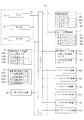
図3は、車両用制御装置100の電気的構成を示したブロック図である。車両用制御装置100は、図3に示すように、CPU71、ROM72及びRAM73を備え、これらはバスライン74を介して入出力ポート75に接続されている。また、入出力ポート75には、車輪駆動装置3等の複数の装置が接続されている。
FIG. 3 is a block diagram showing an electrical configuration of the
CPU71は、バスライン74により接続された各部を制御する演算装置である。ROM72は、CPU71により実行される制御プログラムや固定値データ等を格納した書き換え不能な不揮発性のメモリであり、RAM73は、制御プログラムの実行時に各種のデータを書き換え可能に記憶するためのメモリである。なお、ROM72内には、図7に図示されるフローチャート(キャンバ制御処理)のプログラムが格納されている。
The
車輪駆動装置3は、上述したように、各車輪2(図1参照)を回転駆動するための装置であり、各車輪2に回転駆動力を付与する4個のFL〜RRモータ3FL〜3RRと、それら各モータ3FL〜3RRをCPU71からの命令に基づいて駆動制御する駆動回路(図示せず)とを主に備えている。
As described above, the
キャンバー角調整装置4は、上述したように、各車輪2の舵角とキャンバー角とを調整するための駆動装置であり、各車輪2(車輪駆動装置3)に角度調整のための駆動力を付与する4個のFL〜RRアクチュエータ4FL〜4RRと、それら各アクチュエータ4FL〜4RRをCPU71からの命令に基づいて駆動制御する駆動回路(図示せず)とを主に備えている。
As described above, the camber
なお、FL〜RRアクチュエータ4FL〜4RRは、3本の油圧シリンダ4a〜4cと、それら各油圧シリンダ4a〜4cにオイル(油圧)を供給する油圧ポンプ4d(図1参照)と、その油圧ポンプから各油圧シリンダ4a〜4cに供給されるオイルの供給方向を切り換える電磁弁(図示せず)と、各油圧シリンダ4a〜4c(ロッド部)の伸縮量を検出する伸縮センサ(図示せず)とを主に備えて構成されている。
The FL to RR actuators 4FL to 4RR include three
CPU71からの指示に基づいて、キャンバー角調整装置4の駆動回路が油圧ポンプを駆動制御すると、その油圧ポンプから供給されるオイル(油圧)によって、各油圧シリンダ4a〜4cが伸縮駆動される。また、電磁弁がオン/オフされると、各油圧シリンダ4a〜4cの駆動方向(伸長又は収縮)が切り換えられる。
When the drive circuit of the camber
キャンバー角調整装置4の駆動回路は、各油圧シリンダ4a〜4cの伸縮量を伸縮センサにより監視し、CPU71から指示された目標値(伸縮量)に達した油圧シリンダ4a〜4cは、その伸縮駆動が停止される。なお、伸縮センサによる検出結果は、駆動回路からCPU71に出力され、CPU71は、その検出結果に基づいて各車輪2の現在の舵角及びキャンバー角を得ることができる。
The drive circuit of the camber
車両速度センサ装置32は、路面Gに対する車両1の対地速度(絶対値及び進行方向)を検出すると共に、その検出結果をCPU71に出力するための装置であり、前後及び左右方向加速度センサ32a,32bと、それら各加速度センサ32a,32bの検出結果を処理してCPU71に出力する制御回路(図示せず)とを主に備えている。
The vehicle
前後方向加速度センサ32aは、車両1(車体フレームBF)の前後方向(図1上下方向)の加速度を検出するセンサであり、左右方向加速度センサ32bは、車両1(車体フレームBF)の左右方向(図1左右方向)の加速度を検出するセンサである。なお、本実施の形態では、これら各加速度センサ32a,32bが圧電素子を利用した圧電型センサとして構成されている。
The
CPU71は、車両速度センサ装置32の制御回路から入力された各加速度センサ32a,32bの検出結果(加速度値)を時間積分して、2方向(前後及び左右方向)の速度をそれぞれ算出すると共に、それら2方向成分を合成することで、車両1の対地速度(絶対値及び進行方向)を得ることができる。
The
接地荷重センサ装置34は、各車輪2の接地面が路面Gから受ける荷重を検出すると共に、その検出結果をCPU71に出力するための装置であり、各車輪2が受ける荷重をそれぞれ検出するFL〜RR荷重センサ34FL〜34RRと、それら各荷重センサ34FL〜34RRの検出結果を処理してCPU71に出力する処理回路(図示せず)とを備えている。
The ground
なお、本実施の形態では、各荷重センサ34FL〜34RRがピエゾ抵抗型の3軸荷重センサとして構成されている。これら各荷重センサ34FL〜34RRは、各車輪2のサスペンション軸(図示せず)上に配設され、上述した車輪2が路面Gから受ける荷重を車両1の前後方向(仮想軸Xf−Xb方向)、左右方向(仮想軸Yl−Yr方向)及び上下方向(仮想軸Zu−Zd方向)の3方向で検出する(図2(b)参照)。
In the present embodiment, each of the load sensors 34FL to 34RR is configured as a piezoresistive triaxial load sensor. Each of these load sensors 34FL to 34RR is disposed on a suspension shaft (not shown) of each
CPU71は、接地荷重センサ装置34から入力された各荷重センサ34FL〜34RRの検出結果(接地荷重)より、各車輪2の接地面における路面Gの摩擦係数μを次のように推定する。
The
例えば、前輪2FLに着目すると、FL荷重センサ34FLにより検出される車両1の前後方向、左右方向および垂直方向の荷重がそれぞれFx、Fy及びFzであれば、前輪2FLの接地面に対応する部分の路面Gにおける車両1前後方向の摩擦係数μは、前輪2FLが路面Gに対してスリップしているスリップ状態ではFx/Fzとなり(μx=Fx/Fz)、前輪2FLが路面Gに対してスリップしていない非スリップ状態ではFx/Fzよりも大きい値であると推定される(μx>Fx/Fz)。
For example, focusing on the front wheel 2FL, if the loads in the front-rear direction, the left-right direction, and the vertical direction of the
なお、車両1の左右方向の摩擦係数μyについても同様であり、スリップ状態ではμy=Fy/Fzとなり、非スリップ状態ではFy/Fzよりも大きな値と推定される。また、摩擦係数μを他の手法により検出することは当然可能である。他の手法としては、例えば、特開2001−315633号公報や特開2003−118554号に開示される公知の技術が例示される。
The same applies to the friction coefficient μy in the left-right direction of the
車輪回転速度センサ装置35は、各車輪2の回転速度を検出すると共に、その検出結果をCPU71に出力するための装置であり、各車輪2の回転速度をそれぞれ検出する4個のFL〜RR回転速度センサ35FL〜35RRと、それら各回転速度センサ35FL〜35RRの検出結果を処理してCPU71に出力する処理回路(図示せず)とを備えている。
The wheel rotation
なお、本実施の形態では、各回転センサ35FL〜35RRが各車輪2に設けられ、各車輪2の角速度を回転速度として検出する。即ち、各回転センサ35FL〜35RRは、各車輪2に連動して回転する回転体と、その回転体の周方向に多数形成された歯の有無を電磁的に検出するピックアップとを備えた電磁ピックアップ式のセンサとして構成されている。
In this embodiment, each rotation sensor 35FL-35RR is provided in each
CPU71は、車輪回転速度センサ装置35から入力された各車輪2の回転速度と、予めROM72に記憶されている各車輪2の外径とから、各車輪2の実際の周速度をそれぞれ得ることができ、その周速度と車両1の走行速度(対地速度)とを比較することで、各車輪2がスリップしているか否かを判断することができる。
The
アクセルペダルセンサ装置52aは、アクセルペダル52の操作状態を検出すると共に、その検出結果をCPU71に出力するための装置であり、アクセルペダル52の踏み込み状態を検出する角度センサ(図示せず)と、その角度センサの検出結果を処理してCPU71に出力する制御回路(図示せず)とを主に備えている。
The accelerator
ブレーキペダルセンサ装置53aは、ブレーキペダル53の操作状態を検出すると共に、その検出結果をCPU71に出力するための装置であり、ブレーキペダル53の踏み込み状態を検出する角度センサ(図示せず)と、その角度センサの検出結果を処理してCPU71に出力する制御回路(図示せず)とを主に備えている。
The brake
ステアリングセンサ装置54aは、ステアリング54の操作状態を検出すると共に、その検出結果をCPU71に出力するための装置であり、ステアリング54の操作状態を検出する角度センサ(図示せず)と、その角度センサの検出結果を処理してCPU71に出力する制御回路(図示せず)とを主に備えている。
The
ワイパスイッチセンサ装置55aは、ワイパースイッチ55の操作状態を検出すると共に、その検出結果をCPU71に出力するための装置であり、ワイパースイッチ55の操作状態(操作位置)を検出するポジショニングセンサ(図示せず)と、そのポジショニングセンサの検出結果を処理してCPU71に出力する制御回路(図示せず)とを主に備えている。
The wiper
ウィンカスイッチセンサ装置56aは、ウィンカスイッチ56の操作状態を検出すると共に、その検出結果をCPU71に出力するための装置であり、ウィンカスイッチ56の操作状態(操作位置)を検出するポジショニングセンサ(図示せず)と、そのポジショニングセンサの検出結果を処理してCPU71に出力する制御回路(図示せず)とを主に備えている。
The winker
高グリップスイッチセンサ装置57aは、高グリップスイッチ57の操作状態を検出すると共に、その検出結果をCPU71に出力するための装置であり、高グリップスイッチ57の操作状態(操作位置)を検出するポジショニングセンサ(図示せず)と、そのポジショニングセンサの検出結果を処理してCPU71に出力する制御回路(図示せず)とを主に備えている。
The high grip switch sensor device 57a is a device for detecting the operation state of the
なお、本実施の形態では、各角度センサが電気抵抗を利用した接触型のポテンショメータとして構成されている。CPU71は、各センサ装置52a〜54aの制御回路から入力された検出結果により各ペダル52,53の踏み込み量及びステアリング54の操作角を得ると共に、その検出結果を時間微分することにより、各ペダル52,53の踏み込み速度(操作速度)及びステアリング54の回転速度(操作速度)を得ることができる。
In the present embodiment, each angle sensor is configured as a contact-type potentiometer using electric resistance. The
図3に示す他の入出力装置35としては、例えば、雨量を検出するための雨量センサや路面Gの状態を非接触で検出する光学センサなどが例示される。
Examples of the other input /
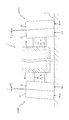
次いで、図4から図6を参照して、車輪2の詳細構成について説明する。図4は、車両1の上面視を模式的に示した模式図である。図5及び図6は、車両1の正面視を模式的に図示した模式図であり、図5では、車輪2にネガティブキャンバーが付与された状態が図示され、図6では、車輪2にポジティブキャンバーが付与された状態が図示されている。
Next, the detailed configuration of the
上述したように、車輪2は、第1トレッド21及び第2トレッド22の2種類のトレッドを備え、図4に示すように、各車輪2(前輪2FL,2FR及び後輪2RL,2RR)において、第1トレッド21が車両1の内側に配置され、第2トレッド22が車両1の外側に配置されている。
As described above, the
本実施の形態では、両トレッド21,22の幅寸法(図4左右方向寸法)が同一に構成されている。また、第1トレッド21は、第2トレッド22に比して、グリップ力の高い特性(高グリップ性)に構成される。一方、第2トレッド22は、第1トレッド21に比して、転がり抵抗の小さい特性(低転がり抵抗)に構成されている。
In the present embodiment, both treads 21 and 22 have the same width dimension (dimension in the left-right direction in FIG. 4). Further, the
例えば、図5に示すように、キャンバー角調整装置4が作動制御され、車輪2のキャンバー角θL,θRがマイナス方向(ネガティブキャンバー)に調整されると、車両1の内側に配置される第1トレッド21の接地圧Rinが増加されると共に、車両1の外側に配置される第2トレッド22の接地圧Routが減少される。これにより、第1トレッド21の高グリップ性を利用して、走行性能(例えば、旋回性能、加速性能、制動性能或いは雨天時の車両安定性など)の向上を図ることができる。
For example, as shown in FIG. 5, when the camber
一方、図6に示すように、キャンバー各調整装置4が作動制御され、車輪2のキャンバー角θL,θRがプラス方向(ポジティブキャンバー方向)に調整されると、車両1の内側に配置される第1トレッド21の接地圧が減少されると共に、車両1の外側に配置される第2トレッド22の接地圧が増加される。これにより、第2トレッド22の低転がり抵抗を利用して、省燃費性能の向上を図ることができる。
On the other hand, as shown in FIG. 6, when the
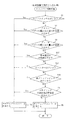
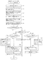
次いで、図7を参照して、キャンバー制御処理について説明する。図7は、キャンバー制御処理を示すフローチャートである。この処理は、車両用制御装置100の電源が投入されている間、CPU71によって繰り返し(例えば、0.2ms間隔で)実行される処理であり、車輪2に付与するキャンバー角を調整することで、上述した走行性能と省燃費性能との2つの性能の両立を図る。
Next, the camber control process will be described with reference to FIG. FIG. 7 is a flowchart showing the camber control process. This process is a process that is repeatedly executed by the CPU 71 (for example, at intervals of 0.2 ms) while the power of the
CPU71は、キャンバー制御処理に関し、まず、ワイパースイッチ55がオンされているか否か、即ち、フロントガラスのワイパーによる拭き取り動作が運転者により指示されているか否かを判断する(S1)。その結果、ワイパースイッチ55がオンされていると判断される場合には(S1:Yes)、現在の天候が雨天であり、路面Gに水膜が形成されている可能性があると推定されるので、車輪2にネガティブキャンバーを付与して(S6)、このキャンバー制御処理を終了する。
Regarding the camber control process, the
これにより、第1トレッド21の接地圧Rinが増加されると共に第2トレッド22の接地圧Routが減少されることで(図5参照)、第1トレッド21の高グリップ性を利用して、雨天時の車両安定性の向上を図ることができる。
As a result, the ground pressure Rin of the
S1の処理において、ワイパースイッチ55はオンされていないと判断される場合には(S1:No)、雨天ではなく、路面Gの状態は良好であると推定されるので、次いで、アクセルペダル52の踏み込み量は所定値以上であるか否か、即ち、所定以上の加速(急加速)が運転者により指示されているか否かを判断する(S2)。
In the process of S1, when it is determined that the
その結果、アクセルペダル52の踏み込み量が所定値以上であると判断される場合には(S2:Yes)、急加速が運転者より指示されており、車輪2がスリップするおそれがあるので、車輪2にネガティブキャンバーを付与して(S6)、このキャンバー処理を終了する。
As a result, when it is determined that the depression amount of the
これにより、上述した場合と同様に、第1トレッド21の接地圧Rinが増加されると共に第2トレッド22の接地圧Routが減少されることで(図5参照)、第1トレッド21の高グリップ性を利用して、車輪2のスリップを防止することができ、車両1の加速性能の向上を図ることができる。
As a result, as in the case described above, the ground pressure Rin of the
S2の処理において、アクセルペダル52の踏み込み量が所定値に達していないと判断される場合には(S2:No)、急加速は指示されておらず、緩やかな加速又は定速走行であると推定されるので、次いで、ブレーキペダル53の踏み込み量は所定値以上であるか否か、即ち、所定以上の制動(急制動)が運転者により指示されているか否かを判断する(S3)。
If it is determined in step S2 that the amount of depression of the
その結果、ブレーキペダル53の踏み込み量が所定値以上であると判断される場合には(S3:Yes)、急制動が運転者より指示されており、車輪2がロックするおそれがあるので、車輪2にネガティブキャンバーを付与して(S6)、このキャンバー処理を終了する。
As a result, when it is determined that the amount of depression of the
これにより、上述した場合と同様に、第1トレッド21の接地圧Rinが増加されると共に第2トレッド22の接地圧Routが減少されることで(図5参照)、第1トレッド21の高グリップ性を利用して、車輪2のロックを防止することができ、車両1の制動性能の向上を図ることができる。
As a result, as in the case described above, the ground pressure Rin of the
S3の処理において、ブレーキペダル53の踏み込み量が所定値に達していないと判断される場合には(S3:No)、急制動は指示されておらず、緩やかな制動か加速又は定速走行であると推定されるので、次いで、車両速度(対地速度)は所定値(例えば、時速15km)以下であるか否か、即ち、低速走行であるか否かを判断する(S17)。
In the process of S3, when it is determined that the depression amount of the
その結果、車両速度が所定値以下(即ち、低速走行中)であると判断される場合には(S17:Yes)、車両速度が所定値を越えている場合と比較して、車両1がその後に減速し停車する可能性や加速する可能性も高いといえる。よって、これらの場合には車両1(車輪2)のグリップ力や停止力を予め確保しておく必要があるので、車輪2にネガティブキャンバーを付与して(S6)、このキャンバー処理を終了する。
As a result, when it is determined that the vehicle speed is equal to or lower than the predetermined value (that is, during low-speed traveling) (S17: Yes), the
これにより、上述した場合と同様に、第1トレッド21の接地圧Rinが増加されると共に第2トレッド22の接地圧Routが減少されることで(図5参照)、第1トレッド21の高グリップ性を利用して、車輪2のグリップ力を増加させることで、そのロックやスリップを防止して、車両1の制動性能や加速性能の向上を図ることができる。
As a result, as in the case described above, the ground pressure Rin of the
また、車両1が停車した後は、第1トレッド21の高グリップ性を利用して、車両1(車輪2)の停止力を確保することができるので、車両1を安定した状態で停車させておくことができる。更に、その停車後に再発進する場合には、予め第1トレッドの接地圧Rinが増加されていることで、車輪2がスリップすることを防止して、車両1の再発進をスムーズ且つ高レスポンスで行うことができる。
In addition, after the
S17の処理において、車両速度が所定値よりも大きいと判断される場合には(S17:No)、車両速度が低速ではなく、加減速の際の駆動力・制動力が比較的小さな値になると推定されるので、次いで、ウィンカスイッチ56はオンであるか否か、即ち、右左折や車線変更を行う旨が運転者により指示されているか否かを判断する(S18)。
In the process of S17, when it is determined that the vehicle speed is greater than the predetermined value (S17: No), the vehicle speed is not low and the driving force / braking force during acceleration / deceleration becomes a relatively small value. Then, it is determined whether or not the
その結果、ウィンカスイッチ56がオンであると判断される場合には(S18:Yes)、右左折や車線変更に伴って、車両1の旋回動作やその準備のための減速が行われる可能性が高いので、車輪2にネガティブキャンバーを付与して(S6)、このキャンバー処理を終了する。
As a result, when it is determined that the
これにより、上述した場合と同様に、第1トレッド21の接地圧Rinが増加されると共に第2トレッド22の接地圧Routが減少されることで(図5参照)、第1トレッド21の高グリップ性を利用して、車輪2のスリップを防止することができ、車両1の旋回性能の向上を図ることができる。
As a result, as in the case described above, the ground pressure Rin of the
S18の処理において、ウィンカスイッチ56はオンされていないと判断される場合には(S18:No)、右左折や車線変更に伴う車両1の旋回動作は行われないと推定されるので、次いで、高グリップスイッチ57はオンであるか否か、即ち、車輪2の特性として高グリップ性を選択する旨が運転者により指示されているか否かを判断する(S19)。
In the process of S18, when it is determined that the
その結果、高グリップスイッチ57がオンであると判断される場合には(S19:Yes)、車輪2の特性として高グリップ性が選択されたということであるので、車輪2にネガティブキャンバーを付与して(S6)、このキャンバー処理を終了する。
As a result, when it is determined that the
これにより、上述した場合と同様に、第1トレッド21の接地圧Rinが増加されると共に第2トレッド22の接地圧Routが減少されることで(図5参照)、第1トレッド21の高グリップ性を利用して、車輪2のスリップを防止することができ、車両1の制動性能や加速性能、或いは旋回性能の向上を図ることができる。
As a result, as in the case described above, the ground pressure Rin of the
S19の処理において、高グリップスイッチ57はオンされていないと判断される場合には(S19:No)、次いで、ステアリング54の操作角は所定値以上であるか否か、即ち、所定以上の旋回(急旋回)が運転者により指示されているか否かを判断する(S4)。
In the process of S19, when it is determined that the
その結果、ステアリング54の操作角が所定値以上であると判断される場合には(S4:Yes)、急旋回が運転者より指示されており、車輪2がスリップして、車両1がスピンするおそれがあるので、車輪2にネガティブキャンバーを付与して(S6)、このキャンバー処理を終了する。
As a result, when it is determined that the operation angle of the
これにより、上述した場合と同様に、第1トレッド21の接地圧Rinが増加されると共に第2トレッド22の接地圧Routが減少されることで(図5参照)、第1トレッド21の高グリップ性を利用して、車輪2のスリップ(車両1のスピン)を防止することができ、車両1の旋回性能の向上を図ることができる。
As a result, as in the case described above, the ground pressure Rin of the
一方、S4の処理において、ステアリング54の操作角が所定値に達していないと判断される場合には(S4:No)、急旋回は指示されておらず、緩やかな旋回又は直進走行であり、また、S1からS3の処理より、路面状態は良好であり、急加速や急制動も指示されていないと推定される(S1:No、S2:No、S3:No)。
On the other hand, in the process of S4, when it is determined that the operation angle of the
よって、この場合には(S1:No、S2:No、S3:No、S4:No)、車輪2の性能として高グリップ性を得る必要はなく、低転がり抵抗による省燃費性能を得ることが好ましいと判断できるので、車輪2にポジティブキャンバーを付与して(S5)、このキャンバー処理を終了する。
Therefore, in this case (S1: No, S2: No, S3: No, S4: No), it is not necessary to obtain high grip performance as the performance of the
これにより、第1トレッド21の接地圧Rinが減少されると共に第2トレッド22の接地圧Routが増加されることで(図6参照)、第2トレッド21の低転がり抵抗を利用して、車輪2の転がり効率を向上させることができ、車両1の省燃費性能の向上を図ることができる。
As a result, the ground pressure Rin of the
このように、本実施の形態によれば、キャンバー角調整装置4により車輪2のキャンバー角θR,θLを調整して、第1トレッド21における接地圧Rinと第2トレッド22における接地圧Routとの比率を変更することで、加速性能及び制動性能と省燃費性能との互いに背反する2つの性能の両立を図ることができる。
As described above, according to the present embodiment, the camber angles θR and θL of the
次いで、図8から図11を参照して、第2実施の形態について説明する。図8は、第2実施の形態における車輪202の上面図であり、図9は、車両201の上面視を模式的に示した模式図である。
Next, a second embodiment will be described with reference to FIGS. FIG. 8 is a top view of the
また、図10は、左旋回状態にある車両201の正面視を模式的に図示した模式図であり、左右の車輪2に左旋回用の舵角が付与されると共に、旋回外輪(右の前輪202FR)にネガティブキャンバーが付与され、旋回内輪(左の車輪202FL)にキャンバー定常角が付与された状態が図示されている。
FIG. 10 is a schematic diagram schematically showing a front view of the
第1実施の形態では、車輪2の両トレッド21,22の外径が幅方向に一定とされる場合を説明したが、第2実施の形態における車輪2は、第1トレッド221の外径が漸次縮径するように構成されている。なお、上記した第1実施の形態と同一の部分には同一の符号を付して、その説明は省略する。
In the first embodiment, the case where the outer diameters of both the
第2実施の形態における車輪202は、図8及び図9に示すように、車両201の内側(図8右側)に配置される第1トレッド221と、その第1トレッド221と特性が異なり、車両201の外側(図8左側)に配置される第2トレッド22とを備える。
As shown in FIGS. 8 and 9, the
なお、第1トレッド221は、第2トレッド22に比して、グリップ力の高い特性(高グリップ性)に構成され、第2トレッド22は、第1トレッド221に比して、転がり抵抗の小さい特性(低転がり抵抗)に構成されている。
Note that the
図8及び図9に示すように、車輪202は、両トレッド221,22の幅寸法(図8左右方向寸法)が同一に構成されているが、第2トレッド22における外径が幅方向(図8左右方向)に略一定に構成される一方で、第1トレッド221における外径が第2トレッド22側(図8左側)から車両201の内側(図8右側)に向かうに従って漸次縮径して構成されている。
As shown in FIGS. 8 and 9, the
これにより、図10に示すように、車輪202(左の前輪202FL)に大きなキャンバー角を付与しなくても(即ち、キャンバー角を0°に設定しても)、第1トレッド221が路面Gから離れた状態で、第2トレッド22のみを接地させることができる。その結果、車輪2全体としての転がり抵抗をより小さくして、省燃費性能のより一層の向上を図ることができる。同時に、第1トレッド221が接地せず、かつ、第2トレッド22がより小さなキャンバー角で接地されることより、これら両トレッド221,22の摩耗を抑制して、高寿命化を図ることができる。
As a result, as shown in FIG. 10, the
一方、図10に示すように、車輪202(右の前輪202FR)にマイナス方向へのキャンバー角(ネガティブキャンバー)を付与して、第1トレッド221を接地させる場合には、かかる第1トレッド221の外径が漸次縮径されていることから、第1トレッド221における接地圧を幅方向(図8左右方向)全域において均等化することができ、トレッド端部に接地圧が集中することを抑制することができる。
On the other hand, as shown in FIG. 10, when a negative camber angle (negative camber) is given to the wheel 202 (right front wheel 202FR) and the
よって、高グリップの第1トレッド221を効率的に利用して、走行性能(旋回性能、加速性能、制動性能、雨天時の走行安定性など)のより一層の向上を図ることができると共に、第1トレッド221の偏摩耗を抑制して、高寿命化を図ることができる。
Accordingly, the
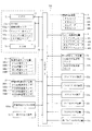
次いで、図11を参照して、第2実施の形態におけるキャンバー制御処理について説明する。図11は、キャンバー制御処理を示すフローチャートである。この処理は、車両用制御装置100の電源が投入されている間、CPU71によって繰り返し(例えば、0.2ms間隔で)実行される処理である。
Next, the camber control process in the second embodiment will be described with reference to FIG. FIG. 11 is a flowchart showing the camber control process. This process is a process executed repeatedly (for example, at intervals of 0.2 ms) by the
CPU71は、キャンバー制御処理に関し、ワイパースイッチ55がオンされていると判断される場合(S1:Yes)、アクセルペダル52の踏み込み量が所定値以上であると判断される場合(S1:No、S2:Yes)、ブレーキペダル53の踏み込み量が所定値以上であると判断される場合(S1:No、S2:No、S3:Yes)、車両速度が所定値以下であると判断される場合(S1:No、S2:No、S3:No、S17:Yes)、ウィンカスイッチ56がオンされていると判断される場合(S1:No、S2:No、S3:No、S17:No、S18:Yes)、及び、高グリップスイッチ57がオンされていると判断される場合には(S1:No、S2:No、S3:No、S17:No、S18:Yes)、上述した第1実施の形態で説明したように、路面Gに水膜が形成されている、急加速・急制動が指示されている、大きな駆動力の発生や停車が予測される、右左折や車線変更に伴う旋回動作が予測される、或いは、高グリップ性の選択が指示されているということであり、第1トレッド221の高グリップ性を利用する必要がある。
Regarding the camber control process, the
よって、この場合には、左右の車輪2にネガティブキャンバー(本実施の形態では、少なくとも第2トレッド22が路面Gから離接するキャンバー角、図10に図示する右の前輪202FRを参照)を付与して(S27)、このキャンバー処理を終了する。
Therefore, in this case, a negative camber (in this embodiment, at least the camber angle at which the
これにより、上述した第1実施の形態の場合と同様に、第1トレッド221の接地圧Rinが増加されると共に第2トレッド22の接地圧Routが減少される(本実施の形態では接地圧Routが0となる)ことで、第1トレッド221の高グリップ性を利用して、車輪2のスリップ・ロックを防止することができ、車両201の走行安定性や加速・制動性能の向上を図ることができる。
As a result, as in the case of the first embodiment described above, the ground pressure Rin of the
なお、左右の車輪2に付与するキャンバー角θR,θLは直進走行時であれは同じ角度であることが好ましい。また、そのキャンバー角θR,θLは第2トレッド22が路面Gから離接する以上の角度であることが好ましい。
In addition, it is preferable that the camber angles θR and θL applied to the left and
一方、S4の処理において、ステアリング54の操作角が所定値に達していないと判断される場合には(S4:No)、急旋回は指示されておらず、緩やかな旋回又は直進走行であり、また、S1からS3の処理より、路面状態は良好であり、急加速や急制動も指示されておらず、大きな駆動力の発生や停車は予測されず、右左折や車線変更に伴う旋回動作も予測されず、更に、高グリップ性の選択は指示されていないと推定される(S1:No、S2:No、S3:No、S17:No、S18:No、S19:No)。
On the other hand, in the process of S4, when it is determined that the operation angle of the
よって、この場合には(S1:No、S2:No、S3:No、S17:No、S18:No、S19:No、S4:No)、車輪2の性能として高グリップ性を得る必要はなく、低転がり抵抗による省燃費性能を得ることが好ましいと判断できるので、車輪2にキャンバー定常角を付与して(S25)、このキャンバー処理を終了する。なお、本実施の形態では、キャンバー定常角が0°(図10に図示する左の前輪202FL参照)に設定される。
Therefore, in this case (S1: No, S2: No, S3: No, S17: No, S18: No, S19: No, S4: No), it is not necessary to obtain high grip performance as the performance of the
これにより、第1トレッド221が路面Gから離れた状態で、第2トレッド22のみを接地させることができるので、車輪202全体としての転がり抵抗をより小さくして、省燃費性能のより一層の向上を図ることができる。また、この場合には、第1トレッド221が接地せず、かつ、キャンバー角が0°で第2トレッド22が接地されることで、これら両トレッド221,22の摩耗を抑制して、高寿命化を図ることができる。
Accordingly, only the
また、S4の処理において、ステアリング54の操作角が所定値以上であると判断される場合には(S4:Yes)、急旋回が運転者より指示されており、車輪2がスリップして、車両201がスピンするおそれがある。そこで、本実施の形態では、旋回外輪(図10では右の前輪202FR)にネガティブキャンバーを付与すると共に、旋回内輪(図10では左の前輪202FL)にキャンバー定常角を付与して(S26)、このキャンバー処理を終了する。
In the process of S4, when it is determined that the operation angle of the
これにより、旋回性能を確保しつつ、制御駆動コストの削減を図ることができる。即ち、旋回外輪では、第1トレッド221の接地圧Rinが増加されると共に第2トレッド22の接地圧Routが減少される(本実施の形態では0となる)ことで(図10参照)、第1トレッド221の高グリップ性を利用して、車輪202のスリップ(車両201のスピン)を防止することができ、車両201の旋回性能の向上を図ることができる。一方、旋回内輪では、そのキャンバー角の変化を旋回外輪よりも少なくする(即ち、直進走行時のキャンバー角をそのまま維持する)ことで、車両用制御装置100の制御コスト或いはキャンバー角調整装置4の駆動コストの削減を図ることができる。
As a result, it is possible to reduce the control drive cost while ensuring the turning performance. That is, in the turning outer wheel, the ground pressure Rin of the
次いで、図12から図14を参照して、第3実施の形態について説明する。図12は、第3実施の形態における車輪302の上面図である。また、図13は、左旋回状態にある車両301の正面視を模式的に図示した模式図であり、左右の車輪302に左旋回用の舵角が付与されると共に、旋回外輪(右の前輪302FR)にネガティブキャンバーが付与され、旋回内輪(左の車輪302FL)にポジティブキャンバーが付与された状態が図示されている。
Next, a third embodiment will be described with reference to FIGS. FIG. 12 is a top view of the
第1実施の形態では、車輪2の両トレッド21,22の外径が幅方向に一定とされる場合を説明したが、第3実施の形態における車輪302は、第1トレッド221の外径と第3トレッド323の外径とが漸次縮径するように構成されている。なお、上記した各実施の形態と同一の部分には同一の符号を付して、その説明は省略する。
In the first embodiment, the case where the outer diameters of both the
第3実施の形態における車輪302は、図12に示すように、第3トレッド323を備え、第1トレッド221が車両301の内側(図12右側)に配置されると共に、第3トレッド323が車両301の外側(図12左側)に配置され、第2トレッド22が第1トレッド221と第3トレッド323との間に配置されている。
As shown in FIG. 12, the
そして、第3トレッド323は、少なくとも第2トレッド22に比して、グリップ力の高い特性に構成されると共に、その第3トレッド323の外径は、図12に示すように、第2トレッド22側(図12右側)から車両301の外側(図12左側)に向かうに従って漸次縮径して構成されている。
The
これにより、車輪302に大きなキャンバー角を付与することなく(例えば、キャンバー角を0°に設定しても)、第1トレッド221及び第3トレッド323が路面Gから離れた状態で、第2トレッド22のみを接地させることができる。これにより、車輪302全体としての転がり抵抗をより小さくして、省燃費性能のより一層の向上を図ることができる。
As a result, the second tread is in a state where the
同時に、第1トレッド221及び第3トレッド323が接地せず、かつ、第2トレッド22がより小さなキャンバー角で接地されることより、これら各トレッド221,22,323の摩耗を抑制して、高寿命化を図ることができる。
At the same time, since the
一方、車輪302にプラス方向へのキャンバー角(ポジティブキャンバー)を付与して、第3トレッド323を接地させる場合には、かかる第3トレッド323の外径が漸次縮径されていることから、第3トレッド323における接地圧を幅方向(図12左右方向)全域において均等化することができ、トレッド端部に接地圧が集中することを抑制することができる。
On the other hand, when the camber angle (positive camber) in the plus direction is given to the
よって、高グリップ性の第3トレッド323を効率的に利用して、走行性能(旋回性能、加速性能、制動性能、雨天時の走行安定性など)のより一層の向上を図ることができると共に、偏摩耗を抑制して、高寿命化を図ることができる。
Therefore, the
次いで、図14を参照して、第3実施の形態におけるキャンバー制御処理について説明する。図14は、キャンバー制御処理を示すフローチャートである。この処理は、車両用制御装置100の電源が投入されている間、CPU71によって繰り返し(例えば、0.2ms間隔で)実行される処理である。
Next, the camber control process in the third embodiment will be described with reference to FIG. FIG. 14 is a flowchart showing the camber control process. This process is a process executed repeatedly (for example, at intervals of 0.2 ms) by the
CPU71は、S4の処理において、ステアリング54の操作角が所定値に達していないと判断される場合には(S4:No)、急旋回は指示されておらず、緩やかな旋回又は直進走行であり、また、S1からS3及びS17からS19の処理より、路面状態は良好であり、急加速や急制動も指示されておらず、大きな駆動力の発生や停車は予測されず、右左折や車線変更に伴う旋回動作も予測されず、更に、高グリップ性の選択は指示されていないと推定される(S1:No、S2:No、S3:No、S17:No、S18:No、S19:No)。
In the process of S4, when it is determined that the operation angle of the
よって、この場合には(S1:No、S2:No、S3:No、S17:No、S18:No、S19:No、S4:No)、車輪302の性能として高グリップ性を得る必要はなく、低転がり抵抗による省燃費性能を得ることが好ましいと判断できるので、車輪2にキャンバー定常角を付与して(S25)、このキャンバー処理を終了する。なお、本実施の形態では、キャンバー定常角が0°(図10に図示する左の前輪202FL参照)に設定される。
Therefore, in this case (S1: No, S2: No, S3: No, S17: No, S18: No, S19: No, S4: No), it is not necessary to obtain high grip performance as the performance of the
これにより、第1トレッド221及び第3トレッド323が路面Gから離れた状態で、第2トレッド22のみを接地させることができるので、車輪302全体としての転がり抵抗をより小さくして、省燃費性能のより一層の向上を図ることができる。また、この場合には、第1トレッド221及び第3トレッド323が接地せず、かつ、キャンバー角が0°で第2トレッド22が接地されることで、これら各トレッド221,22,323の摩耗を抑制して、高寿命化を図ることができる。
Accordingly, only the
また、S4の処理において、ステアリング54の操作角が所定値以上であると判断される場合には(S4:Yes)、急旋回が運転者より指示されており、車輪2がスリップして、車両301がスピンするおそれがある。そこで、本実施の形態では、旋回外輪(図13では右の前輪202FR)にネガティブキャンバーを付与すると共に、旋回内輪(図13では左の前輪202FL)にポジティブキャンバーを付与して(S36)、このキャンバー処理を終了する。
In the process of S4, when it is determined that the operation angle of the
即ち、S36の処理では、図13に示すように、左右の車輪320がいずれも旋回内方側(図13右側)に傾斜するように、キャンバー角θR,θLを付与するので、左右両輪302にそれぞれ横力を発生させて、それら両輪302の横力を旋回力として利用することができるので、旋回性能のより一層の向上を図ることができる。
That is, in the processing of S36, as shown in FIG. 13, camber angles θR and θL are given so that both the left and right wheels 320 are inclined inwardly on the inside of the turn (right side in FIG. 13). Since the lateral force can be generated and the lateral force of both
次いで、図15を参照して、第4実施の形態について説明する。図15は、第4実施の形態におけるキャンバー制御処理を示すフローチャートである。この処理は、車両用制御装置100の電源が投入されている間、CPU71によって繰り返し(例えば、0.2ms間隔で)実行される処理である。
Next, a fourth embodiment will be described with reference to FIG. FIG. 15 is a flowchart illustrating camber control processing according to the fourth embodiment. This process is a process executed repeatedly (for example, at intervals of 0.2 ms) by the
第1実施の形態では、例えば、急加速や急旋回などが運転者により指示された場合に車輪2のキャンバー角を調整する場合を説明したが、第4実施の形態では、スリップした車輪202がある場合にその車輪202のキャンバー角を調整するように構成されている。
In the first embodiment, for example, the case where the camber angle of the
なお、上記した各実施の形態と同一の部分には同一の符号を付して、その説明は省略する。また、第4実施の形態では、第2実施の形態における車両201(車輪202)を車両用制御装置100で制御する場合を例に説明する。
In addition, the same code | symbol is attached | subjected to the part same as each above-mentioned embodiment, and the description is abbreviate | omitted. In the fourth embodiment, a case where the vehicle 201 (wheel 202) in the second embodiment is controlled by the
CPU71は、キャンバー角S4の処理において、まず、車両速度を検出すると共に(S41)、車輪202の回転速度(周速度)を検出し(S42)、これら車両速度と車輪202の周速度とに基づいて、スリップしている車輪202が有るか否かを判断する(S43)。なお、車両速度及び車輪202の周速度は、上述したように、車両速度センサ装置32及び車輪回転速度センサ装置35により算出される。
In the processing of the camber angle S4, the
その結果、S43の処理において、スリップしている車輪202はない、即ち、全ての車輪202が路面Gにグリップして走行していると判断される場合には(S43:No)、車輪202の性能として高グリップ性を得る必要はなく、低転がり抵抗による省燃費性能を得ることが好ましいと判断できるので、車輪202にキャンバー定常角(第2実施の形態の場合と同様に0°)を付与して(S44)、このキャンバー処理を終了する。
As a result, in the process of S43, when it is determined that there is no slipping
これにより、第1トレッド221が路面Gから離れた状態で、第2トレッド22のみを接地させることができるので、車輪202全体としての転がり抵抗をより小さくして、省燃費性能のより一層の向上を図ることができる。また、この場合には、第1トレッド221が接地せず、かつ、キャンバー角が0°で第2トレッド22が接地されることで、これら両トレッド221,22の摩耗を抑制して、高寿命化を図ることができる。
Accordingly, only the
一方、S43の処理において、スリップしている車輪202があると判断される場合には(S43:Yes)、車両201の加速性能や走行安定性が損なわれるおそれがあるので、スリップしている車輪202にネガティブキャンバーを付与して(S45)、このキャンバー処理を終了する。
On the other hand, if it is determined that there is a slipping
これにより、上述した第1実施の形態の場合と同様に、第1トレッド221の接地圧Rinが増加されると共に第2トレッド22の接地圧Routが減少される(本実施の形態では接地圧Routが0となる)ことで、第1トレッド221の高グリップ性を利用して、車輪202のスリップを防止することができ、車両201の加速性能や走行安定性の向上を図ることができる。
As a result, as in the case of the first embodiment described above, the ground pressure Rin of the
次いで、図16から図19を参照して、第5実施の形態について説明する。第1実施の形態では、車輪2にネガティブキャンバー又はポジティブキャンバーを付与する場合に、そのキャンバー角が車両1の走行状態に寄らず一定値である場合を説明したが、第5実施の形態では、車両1の走行状態に応じて、車輪2に付与されるキャンバー角の大きさが増減するように構成されている。
Next, a fifth embodiment will be described with reference to FIGS. 16 to 19. In the first embodiment, when a negative camber or a positive camber is applied to the
なお、上記した各実施の形態と同一の部分には同一の符号を付して、その説明は省略する。また、第5実施の形態では、第1実施の形態における車両1(車輪2)を車両用制御装置500で制御する場合を例に説明する。
In addition, the same code | symbol is attached | subjected to the part same as each above-mentioned embodiment, and the description is abbreviate | omitted. In the fifth embodiment, a case where the vehicle 1 (wheel 2) in the first embodiment is controlled by the
図16は、第5実施の形態における車両用制御装置500の電気的構成を示したブロック図である。車両用制御装置500は、図16に示すように、CPU71、ROM572及びRAM73を備え、これらはバスライン74を介して入出力ポート75に接続されている。第5実施の形態におけるROM572には、摩擦係数マップ572aとキャンバー角マップ572bとが設けられている。なお、これら両マップ572a,572bの詳細については、図17及び図18を参照して後述する。
FIG. 16 is a block diagram showing an electrical configuration of a
路面状況スイッチセンサ装置558aは、路面状況スイッチ(図示せず)の操作状態を検出すると共に、その検出結果をCPU71に出力するための装置であり、路面状況スイッチの操作状態(操作位置)を検出するポジショニングセンサ(図示せず)と、そのポジショニングセンサの検出結果を処理してCPU71に出力する制御回路(図示せず)とを主に備えている。
The road surface state
なお、路面状況スイッチは、運転者により操作される操作部材であり、走行路面の状況に応じて、運転者により路面状況スイッチが切り換えられると、その操作状態(操作位置)に応じて、キャンバー角調整装置4の作動制御がCPU71により行われる。具体的には、路面状況スイッチは、3段式(3ポジション式)のロッカースイッチとして構成され、第1位置は走行路面が乾燥舗装路である状態に、第2位置は走行路面が未舗装路である状態に、第3位置は走行路面が雨天舗装路である状態に。それぞれ対応する。
The road surface state switch is an operation member operated by the driver. When the road surface state switch is switched by the driver according to the road surface state, the camber angle is changed according to the operation state (operation position). Operation control of the adjusting
図17は、摩擦係数マップ572aの内容を模式的に図示した模式図である。摩擦係数マップ572aは、アクセルペダル52及びブレーキペダル53の踏み込み量(操作量)と必要前後摩擦係数との関係を記憶したマップである。
FIG. 17 is a schematic diagram schematically showing the contents of the friction coefficient map 572a. The friction coefficient map 572a is a map that stores the relationship between the depression amount (operation amount) of the
CPU71は、この摩擦係数マップ572aの内容に基づいて、現在の車両1の走行状態において車輪2が発揮すべき摩擦係数(即ち、車輪2にスリップやロックを生じさせないために必要な摩擦係数)を算出する。なお、縦軸に示した必要前後摩擦係数は、車輪2にスリップ又はロックを生じさせないために必要な車両前後方向(図1上下方向)における摩擦係数である。
Based on the content of the friction coefficient map 572a, the
この摩擦係数マップ572aによれば、図17に示すように、アクセルペダル52及びブレーキペダル53が操作されていない状態(アクセル及びブレーキ操作量=0)では、必要前後摩擦係数が最小値μfminに規定されると共に、アクセルペダル52又はブレーキペダル53の操作量(踏み込み量)に比例して、必要前後摩擦係数が直線的に変化し、アクセルペダル52又はブレーキペダル53の操作量が最大に操作された状態(アクセル操作量=100%)において、必要前後摩擦係数が最大値μfmaxとなるように規定されている。
According to the friction coefficient map 572a, as shown in FIG. 17, when the
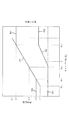
図18は、キャンバー角マップ572bの内容を模式的に図示した模式図である。キャンバー角マップ572bは、車輪2の摩擦係数及び転がり抵抗とキャンバー角との関係を記憶したマップであり、車輪2を使用した予備試験で実測された値が記憶されている。
FIG. 18 is a schematic diagram schematically showing the contents of the camber angle map 572b. The camber angle map 572b is a map in which the friction coefficient of the
CPU71は、このキャンバー角マップ572bの内容に基づいて、車輪2に付与すべきキャンバー角を算出する。
The
なお、図18において、実線501は摩擦係数に、実線502は転がり抵抗に、それぞれ対応する。また、横軸のキャンバー角は、図18右側(角度0度よりもθa側)がネガティブキャンバー(即ち、高グリップの第1トレッド21の接地圧が増加する側、図5参照)に、図18左側(角度0度よりもθb側)がポジティブキャンバー(即ち、低転がり抵抗の第2トレッド22の接地圧が増加する側、図6参照)に、それぞれ対応する。
In FIG. 18, the
ここで、キャンバー角マップ572bには、上述した路面状況スイッチの3種類の操作状態に対応して、3種類のマップが記憶されているが、図18では、図面を簡素化して理解を容易とするべく、1種類のマップ(乾燥舗装路用マップ)のみを代表例として図示し、他の2種類についてはその図示を省略している。 Here, the camber angle map 572b stores three types of maps corresponding to the three types of operation states of the above-described road surface condition switch, but FIG. 18 simplifies the drawing and facilitates understanding. Therefore, only one type of map (dry pavement map) is shown as a representative example, and the other two types are not shown.
即ち、キャンバー角マップ572bには、乾燥舗装路用マップ、未舗装用マップ及び雨天舗装路用マップの3種類が記憶されており、CPU71は、路面状況スイッチの操作状態を検出し、乾燥舗装路が指示されている場合には乾燥舗装路用マップを、未舗装路が指示されている場合には未舗装路用マップを、雨天舗装路が指示されている場合には雨天舗装路用マップを、それぞれ読み出し、その内容に基づいて、キャンバー角調整装置4の作動制御を行う。
That is, the camber angle map 572b stores three types of maps, a dry pavement map, an unpaved map, and a wet pavement map, and the
このキャンバー角マップ572bによれば、図18に示すように、キャンバー角が0度の状態(即ち、第1トレッド21と第2トレッド22とが均等に接地している状態)から、ネガティブキャンバー側(θa側)へ向けて変化すると、かかる変化に伴って、高グリップ特性の第1トレッド21の接地圧が漸次増加する(低転がり抵抗の第2トレッド22の接地圧が漸次減少する)ことで、摩擦係数(及び転がり抵抗)が漸次増加するように規定されている。
According to the camber angle map 572b, as shown in FIG. 18, from the state where the camber angle is 0 degrees (that is, the state where the
そして、キャンバー角がθa(以下、「第2キャンバー角θa」と称す。)に達すると、第2トレッド22が走行路面から離間され、第1トレッド21のみが走行路面に接地した状態となることで、摩擦係数が最大値μaに達する。
When the camber angle reaches θa (hereinafter referred to as “second camber angle θa”), the
なお、キャンバー角が第2キャンバー角θaからネガティブキャンバー側へ向けて更に変化しても、第2トレッド22が既に走行路面から離間されているので、摩擦係数の変化はほとんど生じず、摩擦係数は最大値μaに維持される。また、転がり抵抗の変化も同様であり、第2キャンバー角θaで最大値となり、その後はほぼ一定値を維持する。
Even if the camber angle further changes from the second camber angle θa toward the negative camber side, since the
一方、図18に示すように、キャンバー角が0度の状態(即ち、第1トレッド21と第2トレッド22とが均等に接地している状態)から、ポジティブキャンバー側(θb側)へ向けて変化すると、かかる変化に伴って、低転がり抵抗の第2トレッド22の接地圧が漸次増加する(高グリップ特性の第1トレッド21の接地圧が漸次減少する)ことで、摩擦係数(及び転がり抵抗)が漸次減少するように規定されている。
On the other hand, as shown in FIG. 18, from the state where the camber angle is 0 degrees (that is, the state where the
そして、キャンバー角がθb(以下、「第1キャンバー角θb」と称す。)に達すると、第1トレッド21が走行路面から離間され、第2トレッド22のみが走行路面に接地した状態となることで、摩擦係数が最小値μbに達する。
When the camber angle reaches θb (hereinafter referred to as “first camber angle θb”), the
なお、キャンバー角が第1キャンバー角θbからポジティブキャンバー側へ向けて更に変化しても、第1トレッド21が既に走行路面から離間されているので、摩擦係数の変化はほとんど生じず、摩擦係数は最小値μbに維持される。また、転がり抵抗の変化も同様であり、第1キャンバー角θbで最小値となり、その後はほぼ一定値を維持する。
Even if the camber angle further changes from the first camber angle θb toward the positive camber side, the
ここで、図18で図示を省略した未舗装路面用マップ及び雨天舗装路面用マップについては、乾燥路面用マップの実線を摩擦係数が小さくなる方向へ平行移動した特性である。即ち、摩擦係数が最小値又は最大値となるキャンバー角はいずれのマップにおいても第1又は第2キャンバー角θa,θbである。 Here, the unpaved road surface map and the wet pavement road map, which are not shown in FIG. 18, have characteristics obtained by translating the solid line of the dry road surface map in a direction in which the friction coefficient decreases. That is, the camber angle at which the friction coefficient becomes the minimum value or the maximum value is the first or second camber angle θa, θb in any map.
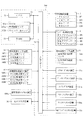
次いで、図19を参照して、第5実施の形態におけるキャンバー制御処理について説明する。図19は、キャンバー制御処理を示すフローチャートである。この処理は、車両用制御装置500の電源が投入されている間、CPU71によって繰り返し(例えば、0.2ms間隔で)実行される処理である。
Next, the camber control process in the fifth embodiment will be described with reference to FIG. FIG. 19 is a flowchart showing the camber control process. This process is a process repeatedly executed by the CPU 71 (for example, at intervals of 0.2 ms) while the power source of the
CPU71は、キャンバー制御処理に関し、まず、路面状況を判断する(S51)。この処理は、路面状況スイッチセンサ装置558a(図16参照)による検出結果を確認し、運転者による路面状況スイッチの操作状態を取得することで行われる。即ち、CPU71は、上述したように、路面状況スイッチの操作位置を第1位置と確認した場合には、路面状況を乾燥路面と判断し、第2位置であれば未舗装路面と判断すると共に、第3位置であれば雨天舗装路面と判断する。
Regarding the camber control process, the
次いで、S52の処理では、アクセルペダル52及びブレーキペダル53の操作状態を検出し(S52)、その検出した操作状態に対応する必要前後摩擦係数を摩擦係数マップ572a(図17参照)から読み出す(S53)。これにより、車輪2にスリップ又はロックを生じさせないために必要な車両前後方向(図1上下方向)における摩擦係数を得ることができる。
Next, in the process of S52, the operation state of the
次いで、S54の処理では、車輪2の舵角及び車両1の対地速度(車速)を検出し(S54)、その検出した舵角及び車速から必要横摩擦係数を算出する(S55)。なお、CPU71は、上述したように、ステアリングセンサ装置54a及び車両速度センサ装置32の検出結果に基づいて、車輪2の舵角及び車両1の対地速度を検出する。
Next, in the process of S54, the steering angle of the
ここで、必要横摩擦係数は、旋回走行中の車両1において、その車輪2にスリップが生じさせないために必要な車両左右方向(図1左右方向)における摩擦係数であり、次に説明するように算出される。
Here, the necessary lateral friction coefficient is a friction coefficient in the left-right direction of the vehicle (the left-right direction in FIG. 1) necessary for preventing the
即ち、まず、車輪2の舵角σ、アッカーマン旋回半径R0及び車両1のホイールベースIの関係は、tanσ=I/R0により表すことができる。この関係式は、舵角σが微小角の場合、σ=I/R0と近似することができる。これをアッカーマン旋回半径R0について変形することで、R0=I/σを得ることができる。
That is, first, the relationship between the steering angle σ of the
一方、車両1の実旋回半径R及び車両1の対地速度(車速)vの関係は、車両1について実測したスタビリティファクターKを使用することで、車両1のステア特性より、R/R0=1+K・v2により表すことができる。これを実旋回半径Rについて変形すると共に、先に求めたアッカーマン旋回半径R0を代入することで、R=I(1+K・v2)/σを得ることができる。
On the other hand, the relationship between the actual turning radius R of the
ここで、旋回走行中に車両1に作用する遠心力Fは、車両1の重量をmとすれば、F=m・v2/Rとなり、これに先に求めた実旋回半径Rを代入することで、F=m・v2・σ/(I(1+K・v2))を得ることができる。車輪2が横方向(車両1の左右方向)にスリップすることを回避するための摩擦力は、この遠心力Fよりも大きな値であれば良いので、必要横摩擦係数μwは、遠心力Fを重量mで割ることで、μw=F/m=v2・σ/(I(1+K・v2))により表すことができる。
Here, if the weight of the
S53及びS55の処理において必要前後摩擦係数及び必要横摩擦係数を得た後は、それら必要前後摩擦係数及び必要横摩擦係数に基づいて(即ち、車両1の前後方向及び左右方向を向くベクトルの合力として)、必要摩擦係数を算出して(S56)、S57の処理へ移行する。 After obtaining the necessary longitudinal friction coefficient and the necessary lateral friction coefficient in the processing of S53 and S55, based on the necessary longitudinal friction coefficient and the necessary lateral friction coefficient (that is, the resultant force of the vectors facing the longitudinal direction and the lateral direction of the vehicle 1) ), A necessary friction coefficient is calculated (S56), and the process proceeds to S57.
S57の処理では、S56の処理において算出した必要摩擦係数と、車輪2が発揮可能な摩擦係数の最大値μa及び最小値μbとを比較し、必要摩擦係数が最小値μb以上かつ最大値μa以下であるか否かを判断する(S57)。
In the process of S57, the required friction coefficient calculated in the process of S56 is compared with the maximum value μa and the minimum value μb of the friction coefficient that the
なお、車輪2が発揮可能な摩擦係数の最大値μa及び最小値μbは、上述したように、キャンバー角マップ572b(図18参照)から読み出される。また、この場合には、CPU71は、S51の処理において判別した路面状況に応じたマップを3種類のマップの中から選択し、その選択したマップの内容に基づいて、最大値μa及び最小値μbを読み出す。
Note that the maximum value μa and the minimum value μb of the friction coefficient that the
S57において判断した結果、必要摩擦係数が最小値μb以上かつ最大値μa以下であると判断される場合には(S57:Yes)、必要摩擦係数に対応する(即ち、必要摩擦係数と同等の摩擦係数となる)キャンバー角をキャンバー角マップ572bから読み出し(S58)、その読み出したキャンバー角を車輪2に付与して(S59)、このキャンバー制御処理を終了する。 As a result of the determination in S57, when it is determined that the required friction coefficient is not less than the minimum value μb and not more than the maximum value μa (S57: Yes), the friction corresponding to the necessary friction coefficient (that is, the friction equivalent to the necessary friction coefficient). The camber angle (which is a coefficient) is read from the camber angle map 572b (S58), the read camber angle is given to the wheel 2 (S59), and this camber control process is terminated.
具体的には、この場合は、例えば、S56の処理において算出された必要摩擦係数がμxであって、μb≦μx≦μaの関係が成り立つということであるので(S57:Yes)、この必要摩擦係数μxに対応するキャンバー角を図18に示すキャンバー角マップ572bからθxと読み出し(S58)、この読み出したキャンバー角θxを車輪2に付与する(S59)。 Specifically, in this case, for example, the necessary friction coefficient calculated in the process of S56 is μx, and the relationship of μb ≦ μx ≦ μa is established (S57: Yes). The camber angle corresponding to the coefficient μx is read as θx from the camber angle map 572b shown in FIG. 18 (S58), and the read camber angle θx is given to the wheel 2 (S59).
これにより、車輪2の発揮する摩擦係数の変更を必要最低限の摩擦係数に制御することができるので、加速・制動性能や旋回性能を必要な分だけ確保しつつも、転がり抵抗をより小さな値に抑制して、より一層の省燃費を達成することができる。
As a result, the change of the friction coefficient exhibited by the
一方、S57の処理において、必要摩擦係数が最小値μb以上かつ最大値μa以下ではないと判断される場合には(S57:No)、次いで、必要摩擦係数が最小値μbよりも小さいか否かを判断する(S60)。その結果、必要摩擦係数が最小値μbよりも小さいと判断される場合には(S60:Yes)、第1キャンバー角を車輪2に付与して(S61)、このキャンバー制御処理を終了する。 On the other hand, in the process of S57, when it is determined that the necessary friction coefficient is not less than the minimum value μb and not more than the maximum value μa (S57: No), then, whether or not the necessary friction coefficient is smaller than the minimum value μb. Is determined (S60). As a result, when it is determined that the necessary friction coefficient is smaller than the minimum value μb (S60: Yes), the first camber angle is given to the wheel 2 (S61), and this camber control process is terminated.
具体的には、この場合は、S56の処理において算出された必要摩擦係数μyが最小値μbよりも小さい(μy<μb)ということであるが(S60:Yes)、上述の場合のように、必要摩擦係数μyに対応するキャンバー角を図18に示すキャンバー角マップ572bから例えばθyと読み出すのではなく、この場合は、車輪2に付与するキャンバー角を第1キャンバー角θbと決定し、これを車輪2に付与する(S61)。
Specifically, in this case, the necessary friction coefficient μy calculated in the process of S56 is smaller than the minimum value μb (μy <μb) (S60: Yes), but as in the above case, The camber angle corresponding to the necessary friction coefficient μy is not read out as, for example, θy from the camber angle map 572b shown in FIG. 18, but in this case, the camber angle applied to the
このように、本実施の形態では、図18に示すように、S56の処理において算出された必要摩擦係数μyが車輪2の発揮できる摩擦係数の最小値μbを下回っている場合、車輪2に第1キャンバー角θbよりも絶対値が大きなキャンバー角を付与しても、それ以上の転がり抵抗の低減(省燃費走行の達成)を見込めないと判断し、車輪2には、最小値μbを発揮可能な範囲内で最も小さい角度(0度に近い角度)、即ち、第1キャンバー角θbを付与する。これにより、キャンバー角が不必要に大きくなることを回避して、車両1の走行安定性を確保することができる。
Thus, in the present embodiment, as shown in FIG. 18, when the necessary friction coefficient μy calculated in the process of S56 is below the minimum value μb of the friction coefficient that the
一方、S60の処理において、必要摩擦係数が最小値μbよりも小さいと判断されない場合には(S60:No)、必要摩擦係数が最大値μaよりも大きいということであるので、この場合には(S60:No)、第2キャンバー角を車輪2に付与すると共に(S62)、報知処理(S63)を実行して、このキャンバー制御処理を終了する。 On the other hand, in the process of S60, if it is not determined that the required friction coefficient is smaller than the minimum value μb (S60: No), it means that the required friction coefficient is larger than the maximum value μa. (S60: No), while giving a 2nd camber angle to the wheel 2 (S62), a notification process (S63) is performed, and this camber control process is complete | finished.
具体的には、この場合は、S56の処理において算出された必要摩擦係数μzが最大値μaよりも大きい(μb<μz)ということであるが(S60:No)、上述の場合のように、必要摩擦係数μzに対応するキャンバー角を図18に示すキャンバー角マップ572bから例えばθzと読み出すのではなく、この場合は、車輪2に付与するキャンバー角を第2キャンバー角θaと決定し、これを車輪2に付与する(S62)。
Specifically, in this case, the necessary friction coefficient μz calculated in the process of S56 is larger than the maximum value μa (μb <μz) (S60: No), but as in the above case, The camber angle corresponding to the necessary friction coefficient μz is not read as, for example, θz from the camber angle map 572b shown in FIG. 18, but in this case, the camber angle applied to the
このように、本実施の形態では、図18に示すように、S56の処理において算出された必要摩擦係数μzが車輪2の発揮できる摩擦係数の最大値μaを越えている場合、車輪2に第2キャンバー角θaよりも絶対値が大きなキャンバー角を付与しても、それ以上の摩擦係数の増加(グリップ性能の向上)を見込めないと判断し、車輪2には、最大値μaを発揮可能な範囲内で最も小さい角度(0度に近い角度)、即ち、第2キャンバー角θaを付与する。これにより、キャンバー角が不必要に大きくなることを回避して、車両1の走行安定性を確保することができる。
As described above, in the present embodiment, as shown in FIG. 18, when the necessary friction coefficient μz calculated in the process of S56 exceeds the maximum value μa of the friction coefficient that the
ここで、報知処理(S63)では、急加速や急制動などによって、車輪2がスリップやロックしている(又はするおそれのある)旨をスピーカーから出力すると共にモニター装置へ表示することで、運転者に対して報知する。なお、車両1が加速状態にある場合には、車両1の速度を低下させる手段(例えば、制動装置の作動による車両1の制動やエンジン等の出力を低下させる)をS63の処理において実行しても良い。これにより、車両1の速度を運転者の操作に寄らず機械的に低下させることができ、安全性の向上に寄与できる。
Here, in the notification process (S63), the fact that the
次いで、図20を参照して、第6実施の形態について説明する。第5実施の形態では、車輪2に第1トレッド21及び第2トレッド22が設けられる場合を説明したが、第6実施の形態では、上述した第3実施の形態の場合と同様に、車輪302に第1トレッド221、第2トレッド22及び第3トレッド323が設けられている。
Next, a sixth embodiment will be described with reference to FIG. In the fifth embodiment, the case where the
なお、上記した各実施の形態と同一の部分には同一の符号を付して、その説明は省略する。また、第6実施の形態では、第3実施の形態における車両301(車輪302、図12又は図13参照)を第5実施の形態における車両用制御装置500で制御する場合を例に説明する。但し、第6実施の形態では、第5実施の形態に対して、後述するように、キャンバー角マップの構成が異なる。
In addition, the same code | symbol is attached | subjected to the part same as each above-mentioned embodiment, and the description is abbreviate | omitted. In the sixth embodiment, a case where the vehicle 301 (
図20は、第6実施の形態におけるキャンバー角マップの内容を模式的に図示した模式図である。キャンバー角マップは、車輪302の摩擦係数及び転がり抵抗とキャンバー角との関係を記憶したマップであり、車輪302を使用した予備試験で実測された値が記憶されている。CPU71は、上述した第5実施の形態の場合と同様に、このキャンバー角マップの内容に基づいて、車輪302に付与すべきキャンバー角を算出する。
FIG. 20 is a schematic diagram schematically showing the contents of a camber angle map in the sixth embodiment. The camber angle map is a map in which the friction coefficient of the
なお、図20において、実線601は摩擦係数に、実線602は転がり抵抗に、それぞれ対応する。また、第6実施の形態におけるキャンバー角マップには、第5実施の形態の場合と同様に、路面状況スイッチの3種類の操作状態に対応して、3種類のマップが記憶されているが、図20では、図面を簡素化して理解を容易とするべく、1種類のマップ(乾燥舗装路用マップ)のみを代表例として図示し、他の2種類についてはその図示を省略している。
In FIG. 20, the
第6実施の形態におけるキャンバー角マップによれば、図20に示すように、キャンバー角が0度の状態(即ち、第2トレッド22のみが接地し、第1及び第3トレッド221,323が走行路面から離間している状態)から、ネガティブキャンバー側(θbn側)へ向けて変化した場合、キャンバー角がθbnまでの間は、第2トレッド22のみが接地し、第1トレッド221(及び第3トレッド323)は走行路面から離間しているので、摩擦係数は最小値μbに維持される。なお、転がり抵抗についても同様であり、この区間においては、最小値を維持する。
According to the camber angle map in the sixth embodiment, as shown in FIG. 20, the camber angle is 0 degree (that is, only the
そして、キャンバー角がθbnから、ネガティブキャンバー側(θan側)へ向けて変化すると、かかる変化に伴って、高グリップ特性の第1トレッド221の接地圧が漸次増加する(低転がり抵抗の第2トレッド22の接地圧が漸次減少する)ことで、摩擦係数(及び転がり抵抗)が漸次増加する。
When the camber angle changes from θbn toward the negative camber side (θan side), the contact pressure of the
その後、キャンバー角がθan(以下、「第3キャンバー角θan」と称す。)に達すると、第2トレッド22が走行路面から離間され、第1トレッド221のみが走行路面に接地した状態となることで、摩擦係数が最大値μaに達する。
Thereafter, when the camber angle reaches θan (hereinafter referred to as “third camber angle θan”), the
この場合、キャンバー角が第3キャンバー角θanからネガティブキャンバー側(図20右側)へ向けて更に変化しても、第2トレッド22が既に走行路面から離間されており、走行路面に接地するのは第1トレッド221のみであるので、摩擦係数の変化はほとんど生じず、摩擦係数は最大値μaに維持される。また、転がり抵抗の変化も同様であり、キャンバー角が第3キャンバー角θanに達した時点で最大値となり、その後はほぼ一定値を維持する。
In this case, even if the camber angle further changes from the third camber angle θan toward the negative camber side (the right side in FIG. 20), the
同様に、図20に示すように、キャンバー角が0度の状態(即ち、第2トレッド22のみが接地し、第1及び第3トレッド221,323が走行路面から離間している状態)から、ポジティブキャンバー側(θbp側)へ向けて変化した場合、キャンバー角がθbpまでの間は、第2トレッド22のみが接地し、第3トレッド323(及び第1トレッド221)は走行路面から離間しているので、摩擦係数は最小値μbに維持される。なお、転がり抵抗についても同様であり、この区間においては、最小値を維持する。
Similarly, as shown in FIG. 20, from the state where the camber angle is 0 degrees (that is, the state where only the
そして、キャンバー角がθbpから、ポジティブキャンバー側(θap側)へ向けて変化すると、かかる変化に伴って、高グリップ特性の第3トレッド323の接地圧が漸次増加する(低転がり抵抗の第2トレッド22の接地圧が漸次減少する)ことで、摩擦係数(及び転がり抵抗)が漸次増加する。
When the camber angle changes from θbp to the positive camber side (θap side), the ground pressure of the
その後、キャンバー角がθap(以下、「第4キャンバー角θap」と称す。)に達すると、第2トレッド22が走行路面から離間され、第3トレッド323のみが走行路面に接地した状態となることで、摩擦係数が最大値μaに達する。
Thereafter, when the camber angle reaches θap (hereinafter referred to as “fourth camber angle θap”), the
この場合、キャンバー角が第4キャンバー角θapからポジティブキャンバー側(図20左側)へ向けて更に変化しても、第2トレッド22が既に走行路面から離間されており、走行路面に接地するのは第3トレッド323のみであるので、摩擦係数の変化はほとんど生じず、摩擦係数は最大値μaに維持される。また、転がり抵抗の変化も同様であり、キャンバー角が第4キャンバー角θapに達した時点で最大値となり、その後はほぼ一定値を維持する。
In this case, even if the camber angle further changes from the fourth camber angle θap toward the positive camber side (left side in FIG. 20), the
次いで、図21を参照して、第6実施の形態におけるキャンバー制御処理について説明する。図21は、キャンバー制御処理を示すフローチャートである。この処理は、車両用制御装置500の電源が投入されている間、CPU71によって繰り返し(例えば、0.2ms間隔で)実行される処理である。
Next, a camber control process according to the sixth embodiment will be described with reference to FIG. FIG. 21 is a flowchart showing the camber control process. This process is a process repeatedly executed by the CPU 71 (for example, at intervals of 0.2 ms) while the power source of the
第6実施の形態では、CPU71は、キャンバー制御処理に関し、第5実施の形態の場合と同様に、路面状況を判断した後(S51)、アクセルペダル52及びブレーキペダル53の操作状態を検出し(S52)、その検出した操作状態に対応する必要前後摩擦係数を摩擦係数マップ572a(図17参照)から読み出す(S53)。
In the sixth embodiment, regarding the camber control process, the
S53の処理を実行した後は、車輪302の舵角及び車両1の対地速度(車速)を検出し(S54)、その検出した舵角及び車速から必要横摩擦係数を算出した後(S55)、必要前後摩擦係数及び必要横摩擦係数に基づいて、必要摩擦係数を算出し(S56)、その算出した必要摩擦係数が最小値μb以上かつ最大値μa以下であるか否かを判断する(S57)。
After performing the process of S53, the steering angle of the
その結果、必要摩擦係数が最小値μb以上かつ最大値μa以下であると判断される場合には(S57:Yes)、次いで、ステアリング54の操作角は所定値以上であるか否か、即ち、所定以上の旋回(急旋回)が運転者により指示されているか否かを判断する(S601)。
As a result, when it is determined that the necessary friction coefficient is not less than the minimum value μb and not more than the maximum value μa (S57: Yes), next, whether or not the operation angle of the
その結果、ステアリング54の操作角が所定値以上であると判断される場合には(S601:Yes)、急旋回が運転者より指示されており、スリップのおそれがあると判断し、本実施の形態では、必要摩擦係数に対応する(即ち、必要摩擦係数と同等の摩擦係数となる)キャンバー角であって、旋回外輪がネガティブキャンバーとなり、かつ、旋回内輪がポジティブキャンバーとなるキャンバー角を図20に示すキャンバー角マップから読み出し(S658)、その読み出したキャンバー角を車輪302に付与して(S59)、このキャンバー制御処理を終了する。
As a result, when it is determined that the operation angle of the
これにより、第3実施の形態の場合と同様に、左右の車輪320がいずれも旋回内方側に傾斜するように、キャンバー角を付与することができる(図13参照)。その結果、左右両輪302にそれぞれ横力を発生させて、それら両輪302の横力を旋回力として利用することができ、旋回性能のより一層の向上を図ることができる。
Thus, as in the case of the third embodiment, the camber angle can be given so that both the left and right wheels 320 are inclined inwardly of the turn (see FIG. 13). As a result, lateral forces can be generated in the left and
一方、S601の処理において、ステアリング54の操作角が所定値に達していないと判断される場合には(S601:No)、急旋回は指示されておらず、比較的緩やかな旋回又は直進走行であると判断し、本実施の形態では、必要摩擦係数に対応する(即ち、必要摩擦係数と同等の摩擦係数となる)キャンバー角であって、左右両輪がネガティブキャンバーとなるキャンバー角を図20に示すキャンバー角マップから読み出し(S602)、その読み出したキャンバー角を車輪302に付与して(S59)、このキャンバー制御処理を終了する。これにより、車両301の姿勢を安定に保つことができる。
On the other hand, in the process of S601, when it is determined that the operation angle of the
一方、S57の処理において、必要摩擦係数が最小値μb以上かつ最大値μa以下ではないと判断される場合には(S57:No)、次いで、必要摩擦係数が最小値μbよりも小さいか否かを判断し(S60)。必要摩擦係数が最小値μbよりも小さいと判断される場合には(S60:Yes)、キャンバー定常角を車輪302に付与して(S661)、このキャンバー制御処理を終了する。 On the other hand, in the process of S57, when it is determined that the necessary friction coefficient is not less than the minimum value μb and not more than the maximum value μa (S57: No), then, whether or not the necessary friction coefficient is smaller than the minimum value μb. Is determined (S60). When it is determined that the necessary friction coefficient is smaller than the minimum value μb (S60: Yes), the camber steady angle is given to the wheel 302 (S661), and this camber control process is terminated.
なお、本実施の形態では、キャンバー定常角が0度に設定される。これにより、第1トレッド221及び第3トレッド323が走行路面から離れた状態で、第2トレッド22のみを接地させることができるので、車輪302全体としての転がり抵抗をより小さくして、省燃費性能のより一層の向上を図ることができる。また、この場合には、第1トレッド221及び第3トレッド323が接地せず、かつ、キャンバー角が0度で第2トレッド22が接地されることで、これら各トレッド221,22,323の摩耗を抑制して、高寿命化を図ることができる。更に、キャンバー角が不必要に大きくなることを回避して、車両1の走行安定性を確保することができる。
In the present embodiment, the camber steady angle is set to 0 degrees. Accordingly, only the
一方、S60の処理において、必要摩擦係数が最小値μbよりも小さいと判断されない場合、即ち、必要摩擦係数が最大値μaよりも大きい場合には(S60:No)、次いで、ステアリング54の操作角は所定値以上であるか否か、即ち、所定以上の旋回(急旋回)が運転者により指示されているか否かを判断する(S603)。 On the other hand, if it is not determined that the required friction coefficient is smaller than the minimum value μb in the process of S60, that is, if the required friction coefficient is larger than the maximum value μa (S60: No), then, the operation angle of the steering 54 Is greater than or equal to a predetermined value, that is, it is determined whether or not a turn of more than a predetermined value (rapid turn) is instructed by the driver (S603).
その結果、ステアリング54の操作角が所定値以上であると判断される場合には(S604:Yes)、急旋回が運転者より指示されており、スリップのおそれがあると判断し、本実施の形態では、旋回外輪に上述した第3キャンバー角を付与すると共に旋回内輪に上述した第4キャンバー角を付与する(S605)。
As a result, when it is determined that the operation angle of the
これにより、旋回外輪がネガティブキャンバーとなり、かつ、旋回内輪がポジティブキャンバーとなり、第3実施の形態の場合と同様に、左右の車輪320がいずれも旋回内方側に傾斜するように、キャンバー角を付与することができる(図13参照)。その結果、左右両輪302にそれぞれ横力を発生させて、それら両輪302の横力を旋回力として利用することができ、旋回性能のより一層の向上を図ることができる。
As a result, the turning outer wheel becomes a negative camber and the turning inner wheel becomes a positive camber, and the camber angle is set so that both the left and right wheels 320 are inclined toward the turning inward side as in the case of the third embodiment. It can be given (see FIG. 13). As a result, lateral forces can be generated in the left and
一方、S603の処理において、ステアリング54の操作角が所定値に達していないと判断される場合には(S603:No)、急旋回は指示されておらず、比較的緩やかな旋回又は直進走行であると判断し、本実施の形態では、左右両輪に第3キャンバー角を付与する(S604)。これにより、左右両輪にネガティブキャンバーを付与して、車両301の姿勢を安定に保つことができる。
On the other hand, in the process of S603, when it is determined that the operation angle of the
なお、本実施の形態では、上述した第5実施の形態の場合と同様に、S56の処理において算出された必要摩擦係数が車輪2の発揮できる摩擦係数の最大値μaを越えている場合、車輪302に第3又は第4キャンバー角よりも絶対値が大きなキャンバー角を付与しても、それ以上の摩擦係数の増加(グリップ性能の向上)を見込めないと判断し、車輪302には、最大値μaを発揮可能な範囲内で最も小さい角度(0度に近い角度)、即ち、第3又は第4キャンバー角を付与する。これにより、キャンバー角が不必要に大きくなることを回避して、車両301の走行安定性を確保することができる。
In the present embodiment, as in the case of the fifth embodiment described above, when the necessary friction coefficient calculated in the process of S56 exceeds the maximum friction coefficient μa that the
S604又はS605の処理を実行した後は、報知処理(S63)を実行して、このキャンバー制御処理を終了する。 After executing the process of S604 or S605, a notification process (S63) is executed, and the camber control process is terminated.
次いで、図22から図26を参照して、第7実施の形態について説明する。第5実施の形態では、車輪2が発揮すべき摩擦係数に基づいて車輪2のキャンバー角を調整する場合を説明したが、第7実施の形態では、スリップした車輪2がある場合に、その車輪2のキャンバー角を補正するように構成されている。
Next, a seventh embodiment will be described with reference to FIGS. In the fifth embodiment, the case where the camber angle of the
なお、上記した各実施の形態と同一の部分には同一の符号を付して、その説明は省略する。また、第7実施の形態では、第1実施の形態における車両1(車輪2)を車両用制御装置700で制御する場合を例に説明する。
In addition, the same code | symbol is attached | subjected to the part same as each above-mentioned embodiment, and the description is abbreviate | omitted. In the seventh embodiment, a case where the vehicle 1 (wheel 2) in the first embodiment is controlled by the
図22は、第7実施の形態における車両用制御装置700の電気的構成を示したブロック図である。車両用制御装置700は、図22に示すように、CPU71、ROM772及びRAM73を備え、これらはバスライン74を介して入出力ポート75に接続されている。第7実施の形態におけるROM772には、摩擦係数マップ572aとキャンバー角マップ572bとキャンバー補正マップ772cとトルク補正マップ772dとが設けられている。
FIG. 22 is a block diagram showing an electrical configuration of the
図23は、キャンバー補正マップ772cの内容を模式的に図示した模式図である。キャンバー補正マップ772cは、車輪2のスリップ比sと、車輪2のキャンバー角をマイナス方向(ネガティブキャンバー方向)に補正するためのキャンバー補正角との関係を記憶したマップである。
FIG. 23 is a schematic diagram schematically showing the contents of the camber correction map 772c. The camber correction map 772c is a map that stores the relationship between the slip ratio s of the
CPU71は、スリップした車輪2がある場合に、このキャンバー補正マップ772cの内容に基づいて、車輪2に付与すべきキャンバー補正角を算出する。なお、横軸に示した車輪2のスリップ比sは、車輪2の自由回転時(車輪2がスリップしていない状態で転動していると仮定した場合)における回転速度(周速度)と車輪2の実際の回転速度(周速度)との比率であり、算出方法については後述する。
When there is a slipping
このキャンバー補正マップ772cによれば、図23に示すように、車輪2のスリップ比sが1.02以下の状態では、キャンバー補正角が0度に規定されると共に、スリップ比sの増加に比例して、キャンバー補正角が直線的に変化し、スリップ比sが1.5以上の状態において、キャンバー補正角が|θc|+θdとなるように規定されている。
According to the camber correction map 772c, as shown in FIG. 23, when the slip ratio s of the
よって、スリップした車輪2がある場合には、車輪2のスリップ比sが大きいほど、車輪2のキャンバー角がよりマイナス方向(ネガティブキャンバー方向)に補正される。即ち、車輪2の第1トレッド21における接地圧Rinが増加される一方、第2トレッド22における接地圧Routが減少されることで、第1トレッドの高グリップ性を利用して車輪2のグリップ力が大きくなるように補正される。
Therefore, when there is a slipping
従って、キャンバー補正マップ772cによれば、スリップした車輪2がある場合でも、その車輪2のグリップ力を回復させることができ、かかる車輪2のスリップを防止することができる。また、スリップ比sが大きくなるほど、車輪2のグリップ力が大きくなるようにキャンバー角をマイナス方向(ネガティブキャンバー方向)に補正するので、グリップ力の回復効果をより大きく発揮させることができる。
Therefore, according to the camber correction map 772c, even when there is a slipped
なお、θcは、キャンバー角調整装置4により調整可能な車輪2のマイナス方向(ネガティブキャンバー方向)のキャンバー角であり(以下、「限界キャンバー角θc」と称す。)、θdは、キャンバー角調整装置4により調整可能な車輪2のプラス方向(ポジティブキャンバー方向)のキャンバー角である。
Θc is a camber angle in the negative direction (negative camber direction) of the
ここで、補正前の車輪2のキャンバー角によっては、必ずしもキャンバー補正角に基づいて車輪2のキャンバー角を補正できない場合がある。例えば、補正前の車輪2のキャンバー角が既にマイナス方向(ネガティブキャンバー方向)にある場合には、スリップ比aが1.5以上の状態であっても、キャンバー補正角(|θc|+θd)の分だけ補正する過程において、車輪2のキャンバー角が限界キャンバー角θcに達してしまう。よって、この場合には、車輪2のグリップ力を十分に回復させることができない。
Here, depending on the camber angle of the
そこで、本実施の形態では、車輪2のキャンバー角が限界キャンバー角θcを超える場合に、車輪2のグリップ力を回復させるべく、トルク補正マップ772dが設けられている。
Therefore, in the present embodiment, when the camber angle of the
図24は、トルク補正マップ772dの内容を模式的に図示した模式図である。トルク補正マップ772dは、車輪2のスリップ比と、車輪駆動装置3によって車輪2に付与する回転駆動トルク(回転駆動力)を補正するためのトルク係数との関係を記憶したマップである。
FIG. 24 is a schematic diagram schematically showing the contents of the
CPU71は、スリップした車輪2がある場合、且つ、その車輪2のキャンバー角が限界キャンバー角θcを超える場合に、このトルク補正マップ772dの内容に基づいて、車輪2に付与する回転駆動トルクのトルク補正量を算出する。即ち、CPU71は、車輪2のスリップ比sに対応するトルク係数をトルク指令値に積算することで、車輪2に付与する回転駆動トルクのトルク補正量を算出する。なお、本実施の形態では、算出したトルク補正量に基づいて、全ての車輪2に付与する回転駆動トルクが補正される。
When there is a slipping
このトルク補正マップ772dによれば、図24に示すように、車輪2のスリップ比sが1.02以下の状態では、トルク係数が1に規定されると共に、スリップ比sの増加に比例して、トルク係数が直線的に変化し、スリップ比sが1.5以上の状態において、トルク係数が0.5に規定されている。
According to the
よって、スリップした車輪2がある場合、且つ、その車輪2に付与するキャンバー角が限界キャンバー角θcを超える場合には、車輪2のスリップ比sが大きいほど、車輪2に付与する回転駆動トルクがより低下するように補正される。即ち、車輪2に付与する回転駆動トルクが低下されることで、車輪2の回転駆動トルクの低下を利用して車輪2のグリップ力が大きくなるように補正される。
Therefore, when there is a slipping
従って、トルク補正マップ772dによれば、スリップした車輪2のキャンバー角が限界キャンバー角θcを超える場合でも、その車輪2のグリップ力を回復させることができ、かかる車輪2のスリップを防止することができる。
Therefore, according to the
また、トルク補正マップ772dによれば、車輪2のスリップ比sが小さいほど、トルク係数が1に近づくように規定されているので、車輪2の回転駆動トルクが低下し過ぎることを防止して、車両1の推進力を確保することができる。
Further, according to the
また、トルク補正マップ772dによれば、車輪2のスリップ比sが1.5以上の状態では、トルク係数が0.5に規定されているので、車両1の推進力を確保して、車両1が走行不能となることを防止することができる。
Further, according to the
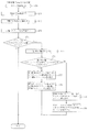
次いで、図25を参照して、第7実施の形態におけるキャンバー制御処理について説明する。図25は、キャンバー制御処理を示すフローチャートである。この処理は、車両用制御装置700の電源が投入されている間、CPU71によって繰り返し(例えば、0.2ms間隔で)実行される処理である。
Next, the camber control process in the seventh embodiment will be described with reference to FIG. FIG. 25 is a flowchart showing the camber control process. This process is a process repeatedly executed by the CPU 71 (for example, at intervals of 0.2 ms) while the power source of the
第7実施の形態では、CPU71は、キャンバー制御処理に関し、第5実施の形態の場合と同様に、路面状況を判断した後(S51)、アクセルペダル52及びブレーキペダル53の操作状態を検出し(S52)、その検出した操作状態に対応する必要前後摩擦係数を摩擦係数マップ572a(図17参照)から読み出す(S53)。
In the seventh embodiment, regarding the camber control process, the
S53の処理を実行した後は、車輪302の舵角及び車両1の対地速度(車速)を検出し(S54)、その検出した舵角及び車速から必要横摩擦係数を算出した後(S55)、必要前後摩擦係数及び必要横摩擦係数に基づいて、必要摩擦係数を算出し(S56)、その算出した必要摩擦係数が最小値μb以上かつ最大値μa以下であるか否かを判断する(S57)。
After performing the process of S53, the steering angle of the
その結果、必要摩擦係数が最小値μb以上かつ最大値μa以下であると判断される場合には(S57:Yes)、必要摩擦係数に対応する(即ち、必要摩擦係数と同等の摩擦係数となる)キャンバー角をキャンバー角マップ572bから読み出し(S58)、その読み出したキャンバー角を車輪2に付与すると共に(S59)、スリップ制御処理(S70)を実行して、このキャンバー制御処理を終了する。 As a result, when it is determined that the necessary friction coefficient is not less than the minimum value μb and not more than the maximum value μa (S57: Yes), it corresponds to the necessary friction coefficient (that is, the friction coefficient is equivalent to the necessary friction coefficient). ) The camber angle is read from the camber angle map 572b (S58), the read camber angle is given to the wheel 2 (S59), the slip control process (S70) is executed, and the camber control process is terminated.
これにより、第5実施の形態の場合と同様に、車輪2の発揮する摩擦係数の変更を必要最低限の摩擦係数に制御することができるので、加速制動性能や旋回性能を必要な分だけ確保しつつも、転がり抵抗をより小さな値に抑制して、より一層の省燃費を達成することができる。
Thus, as in the case of the fifth embodiment, the change of the friction coefficient exhibited by the
ここで、図26を参照して、スリップ制御処理について説明する。図26は、スリップ制御処理(S70)を示すフローチャートである。CPU71は、スリップ制御処理(S70)に関し、まず、車両速度を検出すると共に(S71)、車輪2の回転速度(周速度)を検出し(S72)、これら車両速度と車輪2の周速度とに基づいて各車輪2のスリップ比sをそれぞれ算出する(S73)。
Here, the slip control process will be described with reference to FIG. FIG. 26 is a flowchart showing the slip control process (S70). Regarding the slip control process (S70), the
なお、各車輪2のスリップ比sは、車輪2の自由転動時(即ち、車輪2がスリップしていない状態で転動していると仮定した場合)の周速度Vrfと、車輪2の実際の周速度Vrとを用いて、s=Vr/Vrfにより表すことができる。ここで、周速度Vrは、車輪回転速度センサ装置33から入力された各車輪2の回転速度と、予めROM772に記憶されている各車輪2の外径とからそれぞれ算出される。また、周速度Vrfは、車両1の速度をV、車輪2のスリップ角(車輪2の中心線と車両1の進行方向とがなす角度)をθvとすると、Vrf=V/cosθvにより算出される。
Note that the slip ratio s of each
S73の処理で各車輪2のスリップ比sを算出した後は、このスリップ比sが1.02よりも大きい車輪2はあるか否かを判断する(S74)。その結果、スリップ比sが1.02よりも大きい車輪2はない、即ち、全ての車輪2が路面Gにある程度グリップして走行していると判断される場合には(S74:No)、車輪2のグリップ力を回復させる必要性はないと判断できるので、このスリップ制御処理(S70)を終了する。
After calculating the slip ratio s of each
これにより、車輪2のグリップ力を不必要に向上させることを回避すると共に、第2トレッドの低転がり性を利用して省燃費性能の向上を図ることができる。
Thereby, it is possible to avoid unnecessarily improving the grip force of the
一方、S74の処理において、スリップ比sが1.02よりも大きい車輪2(以下、「過回転車輪」と称す。)がある、即ち、いずれかの車輪2がスリップしていると判断される場合には(S74:Yes)、車輪2の中から過回転車輪を特定し(S75)、その特定した過回転車輪のキャンバー角が限界キャンバー角θcよりも小さいか否かを判断する(S76)。
On the other hand, in the process of S74, it is determined that there is a
その結果、過回転車輪のキャンバー角が限界キャンバー角θcよりも小さいと判断される場合には(S76:Yes)、過回転車輪にマイナス方向(ネガティブキャンバー)のキャンバー角を付与することが可能であると判断できるので、過回転車輪のスリップ比sに対応するキャンバー補正角をキャンバー補正マップ772cから読み出し(S77)、その読み出したキャンバー補正角を過回転車輪に付与して過回転車輪のキャンバー角を補正し(S78)、このスリップ制御処理(S70)を終了する。なお、S75の処理において、過回転車輪であると特定されなかった車輪2については、S76からS78までの処理がスキップされる。即ち、かかる車輪2のキャンバー角は補正されない。
As a result, when it is determined that the camber angle of the overspeed wheel is smaller than the limit camber angle θc (S76: Yes), it is possible to give a negative direction (negative camber) camber angle to the overspeed wheel. Therefore, the camber correction angle corresponding to the slip ratio s of the over-rotating wheel is read from the camber correction map 772c (S77), and the read camber correction angle is given to the over-rotating wheel and the camber angle of the over-rotating wheel is determined. Is corrected (S78), and the slip control process (S70) is terminated. In the process of S75, the process from S76 to S78 is skipped for the
これにより、過回転車輪の第1トレッド21における接地圧Rinが増加される一方、第2トレッド22における接地圧Routが減少されることで、第1トレッドの高グリップ性を利用して過回転車輪のグリップ力を回復させることができ、過回転車輪のスリップを防止することができる。よって、車両1の走行安定性を確保することができる。また、車輪2のスリップを防止することができれば、その分、省燃費性能の向上を図ることができる。
As a result, the ground pressure Rin in the
また、車輪2の中から過回転車輪を特定すると共に、その過回転車輪のキャンバー角を補正するので、過回転車輪のグリップ力を適切に回復させることができる。また、過回転車輪のグリップ力を適切に回復させることができれば、より一層の車両1の走行安定性を確保することができる。
Further, since the overrotating wheel is specified from the
更に、過回転車輪のキャンバー角のみを補正するので、過回転車輪以外の車輪2は第2トレッドの低転がり性を利用して省燃費性能の向上を図ることができる。その結果、路面Gと車輪2の接地面との間の摩擦係数が左右輪で異なる路面(例えば、スプリット路)を走行する場合においても、車両1の走行安定性の確保と省燃費性能の向上との両立を達成することができる。
Furthermore, since only the camber angle of the over-rotating wheel is corrected, the
ここで、S75の処理において、車輪2の中から複数の過回転車輪を特定した場合には、S76の処理では、各過回転車輪のキャンバー角が限界キャンバー角θcよりも小さいか否かをそれぞれ判断する。そして、S76の処理において、各過回転車輪のキャンバー角がいずれも限界キャンバー角θcよりも小さいと判断される場合には(S76:Yes)、各過回転車輪のスリップ比sに対応するキャンバー補正角をキャンバー補正マップ772cからそれぞれ読み出し(S77)、その読み出した各キャンバー補正角を過回転車輪にそれぞれ付与して各過回転車輪のキャンバー角を補正する(S78)。
Here, in the process of S75, when a plurality of over-rotation wheels are specified from the
一方、S76の処理において、過回転車輪のキャンバー角が限界キャンバー角θcよりも小さくない、即ち、過回転車輪のキャンバー角が限界キャンバー角θc以上であると判断される場合には(S76:No)、過回転車輪にこれ以上マイナス方向(ネガティブキャンバー)のキャンバー角を付与することは不可能であると判断できるので、過回転車輪のグリップ力を回復させるべく、過回転車輪のスリップ比sに対応するトルク係数をトルク補正マップ772dから読み出し(S79)、その読み出したトルク係数に基づいて全ての車輪2に付与する回転駆動トルクを補正して(S80)、このスリップ制御処理(S70)を終了する。なお、車輪2に付与する回転駆動トルクの補正は、上述したように、過回転車輪のスリップ比sに対応するトルク係数をトルク指令値に積算することでトルク補正量を算出し、その算出したトルク補正量の分だけ車輪駆動量3をトルク制御することで行われる。
On the other hand, when it is determined in the process of S76 that the camber angle of the over-rotating wheel is not smaller than the limit camber angle θc, that is, the camber angle of the over-rotation wheel is greater than or equal to the limit camber angle θc (S76: No) ) Since it can be judged that it is impossible to give a camber angle in the negative direction (negative camber) to the over-rotating wheel, the slip ratio s of the over-rotating wheel is set to recover the grip force of the over-rotating wheel. The corresponding torque coefficient is read from the
これにより、全ての車輪2に付与する回転駆動トルクが低下されることで、車輪2(過回転車輪を含む)の回転駆動トルクの低下を利用して過回転車輪のグリップ力を回復させることができ、過回転車輪のスリップを防止することができる。よって、車両1の走行安定性を確保することができる。また、車輪2のスリップを防止することができれば、その分、省燃費性能の向上を図ることができる。
As a result, the rotational drive torque applied to all the
ここで、S75の処理において、車輪2の中から複数の過回転車輪を特定した場合で、S76の処理において、各過回転車輪のいずれかのキャンバー角が限界キャンバー角θc以上であると判断される場合には(S76:No)、各過回転車輪のスリップ比sの中で最大値となるスリップ比sに対応するトルク係数をトルク補正マップ772dから読み出し(S79)、その読み出したトルク係数に基づいて全ての車輪2の回転駆動トルクを補正する(S80)。
Here, in the process of S75, when a plurality of over-rotating wheels are specified from the
図25に戻って説明する。S57の処理において、必要摩擦係数が最小値μb以上かつ最大値μa以下ではないと判断される場合には(S57:No)、次いで、必要摩擦係数が最小値μbよりも小さいか否かを判断する(S60)。その結果、必要摩擦係数が最小値μbよりも小さいと判断される場合には(S60:Yes)、第1キャンバー角を車輪2に付与して(S61)、このキャンバー制御処理を終了する。 Returning to FIG. In the process of S57, if it is determined that the required friction coefficient is not less than the minimum value μb and not more than the maximum value μa (S57: No), it is then determined whether the required friction coefficient is smaller than the minimum value μb. (S60). As a result, when it is determined that the necessary friction coefficient is smaller than the minimum value μb (S60: Yes), the first camber angle is given to the wheel 2 (S61), and this camber control process is terminated.
これにより、第5実施の形態の場合と同様に、キャンバー角が不必要に大きくなることを回避して、車両1の走行安定性を確保することができる。
As a result, as in the case of the fifth embodiment, it is possible to avoid the camber angle from becoming unnecessarily large and to ensure the running stability of the
一方、S60の処理において、必要摩擦係数が最小値μbよりも小さいと判断されない場合には(S60:No)、第2キャンバー角を車輪2に付与すると共に(S62)、報知処理(S63)を実行して、このキャンバー制御処理を終了する。 On the other hand, in the process of S60, when it is not determined that the necessary friction coefficient is smaller than the minimum value μb (S60: No), the second camber angle is given to the wheel 2 (S62), and the notification process (S63) is performed. Execute this to finish this camber control process.
これにより、第5実施の形態の場合と同様に、キャンバー角が不必要に大きくなることを回避して、車両1の走行安定性を確保することができる。
As a result, as in the case of the fifth embodiment, it is possible to avoid the camber angle from becoming unnecessarily large and to ensure the running stability of the
上述したように、本実施の形態では、車輪2のスリップ比sが1.02よりも大きい場合に、車輪2のキャンバー角を補正するので、スリップしている車輪2(過回転車輪)のグリップ力を効率的に回復させることができる。
As described above, in the present embodiment, when the slip ratio s of the
また、本実施の形態では、キャンバー補正マップ772cに基づいて、即ち、車輪2のスリップ比sに基づいて車輪2のキャンバー角を補正するので、スリップしている車輪2(過回転車輪)のグリップ力を適切に回復させることができる。
In the present embodiment, since the camber angle of the
ここで、図26に示すフローチャート(スリップ制御処理)において、請求項1記載のスリップ判断手段としてはS74の処理が、キャンバー角変更手段としてはS78の処理が、請求項2記載の車輪特定手段としてはS75の処理が、請求項3記載のスリップ比算出手段としてはS73の処理が、請求項5記載の駆動力制御手段としてはS80の処理が、それぞれ該当する。
Here, in the flowchart (slip control process) shown in FIG. 26, the process of S74 is performed as the slip judging means according to
以上、実施の形態に基づき本発明を説明したが、本発明は上記実施の形態に何ら限定されるものではなく、本発明の趣旨を逸脱しない範囲内で種々の改良変形が可能であることは容易に推察できるものである。 The present invention has been described above based on the embodiments. However, the present invention is not limited to the above embodiments, and various improvements and modifications can be made without departing from the spirit of the present invention. It can be easily guessed.
例えば、上記各実施の形態で挙げた数値は一例であり、他の数値を採用することは当然可能である。また、上記各実施の形態における構成の一部又は全部を他の実施の形態における構成の一部又は全部と組み合わせて構成することは当然可能である。 For example, the numerical values given in the above embodiments are merely examples, and other numerical values can naturally be adopted. In addition, it is naturally possible to configure a part or all of the configurations in the above embodiments in combination with some or all of the configurations in the other embodiments.
上記第1から第3実施の形態では、運転者によるアクセルペダル52又はブレーキペダル53の操作量(踏み込み量)が所定値以上の場合に車輪2にネガティブキャンバーを付与する場合を説明したが(図7S2、S3及びS6参照)、必ずしもこれに限られるものではなく、他の状態量に基づいて車輪2のキャンバー角を決定するように構成することは当然可能である。同様に、上記第5及び第6実施の形態では、摩擦係数マップ572aのパラメータ(横軸)がアクセルペダル52又はブレーキペダル53の操作量(踏み込み量)により構成される場合を説明したが、必ずしもこれに限られるものではなく、他の状態量によりパラメータを構成することは当然可能である。
In the first to third embodiments, a case has been described in which a negative camber is applied to the
ここで、他の状態量としては、例えば、アクセルペダル52又はブレーキペダル53の操作速度が例示される。例えば、アクセルペダル52又はブレーキペダル53の踏み込み量が同一であっても、その操作速度が基準値よりも速い(遅い)場合には、ネガティブキャンバー(ポジティブキャンバー)を付与するように構成しても良い。
Here, as another state quantity, the operation speed of the
或いは、他の状態量としては、例えば、変速機のシフト操作が例示される。例えば、変速機の減速度を上げるシフト操作(シフトダウン操作)が行われた場合に、そのシフト操作により比較的大きな加減速が発生すると判断して、車輪2にネガティブキャンバーを付与するように構成しても良い。これにより、車輪2のスリップやロックを抑制して、車両1の加速性能や制動性能の向上を図ることができる。
Or as another state quantity, shift operation of a transmission is illustrated, for example. For example, when a shift operation (shift down operation) for increasing the deceleration of the transmission is performed, it is determined that a relatively large acceleration / deceleration occurs due to the shift operation, and a negative camber is applied to the
上記第1から第3実施の形態では、運転者によるステアリング54の操作角が所定値以上の場合に車輪2にネガティブキャンバーを付与する場合を説明したが(図7S4及びS6参照)、必ずしもこれに限られるものではなく、他の状態量に基づいて車輪2のキャンバー角を決定するように構成することは当然可能である。
In the first to third embodiments, the case where the negative camber is applied to the
ここで、他の状態量としては、例えば、ステアリング54の操作速度が例示される。例えば、ステアリング54の操作角が同一であっても、その操作速度が基準値よりも速い(遅い)場合には、ネガティブキャンバー(ポジティブキャンバー)を付与するように構成しても良い。
Here, as another state quantity, for example, the operation speed of the
上記第1から第3実施の形態では、請求項3記載の加減速状態判断手段として、各ペダル52,53の操作状態に基づいて判断する処理を例示したが、必ずしもこれに限られるものではなく、例えば、車両速度センサ装置32(前後方向加速度センサ32a、左右方向加速度センサ32b)により検出された実際の加減速度に基づいて判断することは当然可能である。即ち、車両に所定値以上の加減速度が発生した場合に、車輪2にネガティブキャンバーを付与し、所定値に達していない場合にポジティブキャンバーを付与するように構成しても良い。この場合には、車両前後方向と車両左右方向との両方向の加減速度に基づいて判断しても良く、或いは、これら両方向のいずれか一方の加減速度のみに基づいて判断しても良い。
In the first to third embodiments, the acceleration / deceleration state determination means described in
上記第1から第3実施の形態では、請求項5記載の路面判断手段として、ワイパースイッチ55の操作状態に基づいて判断する処理を例示したが、必ずしもこれに限られるものではなく、例えば、雨量センサにより降雨量を検出し、その検出値が所定値以上の場合に、車輪2にネガティブキャンバーを付与するように構成しても良い。或いは、非接触の光学式センサ等で路面の状態を検出し、その検出結果(路面の水膜状態、路面の積雪状態、路面の凍結状態、或いは、舗装状態など)に基づいて、車輪にネガティブキャンバー又はポジティブキャンバーを付与するように構成しても良い。
In the first to third embodiments, the road surface determination means described in claim 5 is exemplified based on the process of determining based on the operation state of the
上記第1から第3実施の形態では、ネガティブキャンバーを付与するか否かの判断順序として、ワイパースイッチ55の状態、アクセルペダル52の状態、ブレーキペダル53の状態、車両速度の状態、ウィンカスイッチ56の状態、高グリップスイッチ57の状態、ステアリング54の状態の順としたが(S1からS4参照)、この順序に限られるものではなく、これらを入れ替えて他の順序とすることは当然可能である。また、これらの判断ステップの一部を省略することも当然可能である。
In the first to third embodiments, the order of determination as to whether or not the negative camber is applied is as follows: wiper switch 55 state,
上記各実施の形態では、左右の車輪2に付与するキャンバー角θR,θLが同じ角度である場合を説明したが(θR=θL)、必ずしもこれに限られるものではなく、左右の車輪2にそれぞれ異なるキャンバー角θR,θLを付与することは当然可能である(θR<θL又はθL<θR)。
In each of the above embodiments, the case where the camber angles θR and θL applied to the left and
上記第1から第3実施の形態では、第1トレッド21,221が車両内側に、第2トレッド22が車両外側に、それぞれ配設される場合を説明したが、この位置関係に限定されるものではなく、各車輪2毎に適宜変更することは当然可能である。
In the first to third embodiments, the case where the first treads 21 and 221 are disposed on the vehicle inner side and the
例えば、第1トレッド21,221が車両外側に、第2トレッド22が車両内側に、それぞれ配設されていても良く、前輪では第1トレッド21,221が車両外側に、後輪では第2トレッド22を車両内側に、それぞれ配設されていても良い。或いは、各車輪2毎にこの位置関係が異なっていても良い。
For example, the first treads 21 and 221 may be disposed on the vehicle outer side, and the
上記第2から第4実施の形態では、キャンバー定常角が0°の場合を説明したが、必ずしもこれに限られるものではなく、キャンバー定常角をポジティブキャンバー又はネガティブキャンバーに設定することは当然可能である。 In the second to fourth embodiments, the case where the camber steady angle is 0 ° has been described. However, the present invention is not necessarily limited to this, and it is naturally possible to set the camber steady angle to a positive camber or a negative camber. is there.
上記各実施の形態では、車輪が2種類のトレッドを有する場合と3種類のトレッドを有する場合とを説明したが、これらの車輪を組み合わせることは当然可能である。例えば、前輪には2種類のトレッドを有する車輪2、202を使用し、後輪には3種類のトレッドを有する車輪303を使用しても良く、この逆でも良い。
In each of the above-described embodiments, the case where the wheel has two types of treads and the case where the wheel has three types of treads have been described, but it is naturally possible to combine these wheels. For example, the
上記各実施の形態では、第1又は第3のトレッド21,221,323が第2のトレッド22に比して高グリップ性の特性を有し、第2のトレッド22が第1又は第3のトレッド21,221,323に比して低転がり性の特性を有する場合を説明したが、これら各トレッド21,221,22,323に他の特性を持たせて構成することは当然可能である。例えば、2種類のトレッドパターン(溝)を設けることで、一のトレッドは排水性の高い特性とし、他のトレッドはロードノイズの小さい特性をするものが例示される。
In each of the above embodiments, the first or
上記第4実施の形態では、車輪2がスリップしているか否かに応じて車輪2のキャンバー角を制御する場合を説明したが(図15S43からS45参照)、必ずしもこれに限られるものではなく、他の状態に基づいて車輪2のキャンバー角を制御することは当然可能である。
In the fourth embodiment, the case where the camber angle of the
他の状態としては、例えば、車輪2が走行する路面の摩擦係数μが例示される。なお、摩擦係数μは上述したように接地荷重センサ装置34により推定することができる。或いは、車輪2がロックしているか否かに基づいて、車輪2のキャンバー角を制御する(ロック時にネガティブキャンバーを付与する)ようにしても良い。
As another state, for example, the friction coefficient μ of the road surface on which the
上記第5及び第6実施の形態では、摩擦係数マップ572aにおいて、アクセル操作量に対する必要前後摩擦係数の変化と、ブレーキ操作量に対する必要前後摩擦係数の変化とが同じ変化となるように構成する場合を説明したが(図17参照)、かかる構成は一例であり、他の構成とすることは当然可能である。 In the fifth and sixth embodiments, in the friction coefficient map 572a, the change in the required front-rear friction coefficient with respect to the accelerator operation amount and the change in the required front-rear friction coefficient with respect to the brake operation amount are configured to be the same change. (See FIG. 17), this configuration is an example, and other configurations are naturally possible.
例えば、アクセル操作量100%における必要前後摩擦係数の最大値とブレーキ操作量100%における必要前後摩擦係数の最大値とが異なる値であっても良い。また、アクセル操作量等の変化に対して必要前後摩擦係数が直線的に変化する場合を説明したが、かかる変化を曲線とすることは当然可能である。 For example, the maximum value of the required front-rear friction coefficient when the accelerator operation amount is 100% may be different from the maximum value of the required front-rear friction coefficient when the brake operation amount is 100%. Moreover, although the case where the required front-rear friction coefficient changes linearly with respect to changes in the accelerator operation amount and the like has been described, it is naturally possible to make such changes into a curve.
上記第5及び第6実施の形態では、車両用制御装置500が1の摩擦係数マップ572aのみを備える場合を説明したが、必ずしもこれに限られるものではなく、複数の摩擦係数マップを備えることは当然可能である。
In the fifth and sixth embodiments, the case where the
例えば、路面の状況に対応してそれぞれ異なる内容で構成される複数の摩擦係数マップ(例えば、路面状況スイッチの操作範囲に対応する乾燥舗装路用マップ、未舗装用マップ及び雨天舗装路用マップの3種類)を準備し、図19のS53の処理においては、路面状況スイッチの操作状態に対応するマップから必要前後摩擦係数を読み出すように構成しても良い。 For example, a plurality of friction coefficient maps (for example, a dry pavement map, an unpaved map, and a rainy pavement map corresponding to the operation range of the road surface switch are configured with different contents corresponding to the road surface conditions. 3 types) may be prepared, and in the process of S53 of FIG. 19, the necessary front-rear friction coefficient may be read from the map corresponding to the operation state of the road surface condition switch.
上記第7実施の形態では、キャンバー補正角をキャンバー補正マップ772cから算出すると共に、その算出したキャンバー補正角に基づいて過回転車輪のキャンバー角を補正する場合を説明したが(図26S77及びS78参照)、必ずしもこれに限られるものではなく、例えば、所定角度だけ過回転車輪のキャンバー角を補正しても良い。この場合には、スリップ制御処理(S70)が繰り返し実行されることで、過回転車輪のグリップ力が徐々に回復される。これにより、スリップ制御処理(S70)を簡素化することができるので、車両用制御装置700の制御負荷を軽減することができる。
In the seventh embodiment, the case where the camber correction angle is calculated from the camber correction map 772c and the camber angle of the over-rotation wheel is corrected based on the calculated camber correction angle has been described (see FIGS. 26S77 and S78). For example, the camber angle of the over-rotating wheel may be corrected by a predetermined angle. In this case, the slip control process (S70) is repeatedly executed, whereby the grip force of the over-rotating wheel is gradually recovered. Thereby, since the slip control process (S70) can be simplified, the control load of the
上記第7実施の形態では、トルク補正量をトルク補正マップ772dに基づいて算出すると共に、その算出したトルク補正量に基づいて車輪2に付与する回転駆動トルクを補正する場合を説明したが(図26S79及びS80参照)、必ずしもこれに限られるものではなく、例えば、所定量だけ車輪2に付与する回転駆動トルクを補正しても良い。この場合には、スリップ制御処理(S70)が繰り返し実行されることで、過回転車輪のグリップ力が徐々に回復される。これにより、スリップ制御処理(S70)を簡素化することができるので、車両用制御装置700の制御負荷を軽減することができる。
In the seventh embodiment, the case where the torque correction amount is calculated based on the
上記第7実施の形態では、全ての車輪2に付与する回転駆動トルクを補正する場合を説明したが(図26S80参照)、必ずしもこれに限られるものではなく、過回転車輪に付与する回転駆動トルクのみを補正しても良い。
In the seventh embodiment, the case where the rotational drive torque applied to all the
上記第7実施の形態では、車輪2のスリップ比sに基づいて車輪2がスリップしているか否かを判断する場合を説明したが(図26S74参照)、必ずしもこれに限られるものではなく、例えば、各車輪2の周速度の比率や各車輪2の回転数の差など、他の車輪2と比較することで車輪2がスリップしているか否かを判断しても良い。
In the seventh embodiment, a case has been described in which it is determined whether or not the
上記第7実施の形態では、車輪回転速度センサ装置33から入力された各車輪2の回転速度と、予めROM772に記憶されている各車輪2の外径とから、各車輪2の実際の周速度をそれぞれ算出する場合を説明したが、必ずしもこれに限られるものではなく、車輪回転速度センサ装置33から入力された各車輪2の回転速度と、予めROM772に記憶した有効回転半径マップ(図27参照)とから、各車輪2の実際の周速度をそれぞれ算出しても良い。ここで、図27を参照して、有効回転半径マップについて説明する。
In the seventh embodiment, the actual peripheral speed of each
図27は、有効回転半径マップの内容を模式的に図示した模式図である。有効回転半径マップは、車輪2のキャンバー角と、車輪2の有効回転半径との関係を記憶したマップである。
FIG. 27 is a schematic diagram schematically showing the contents of the effective rotation radius map. The effective turning radius map is a map that stores the relationship between the camber angle of the
CPU71は、車輪2の実際の周速度を算出する場合に、この有効回転半径マップの内容に基づいて、車輪2の有効回転半径を算出する。なお、横軸のキャンバー角は、図27右側がマイナス方向(ネガティブキャンバー方向)及びプラス方向(ポジティブキャンバー方向)に対応する。
When calculating the actual peripheral speed of the
この有効回転半径マップによれば、図27に示すように、車輪2のキャンバー角が0度の状態から、マイナス方向(ネガティブキャンバー方向)或いはプラス方向(ポジティブキャンバー方向)へ向けて変化すると、かかる変化に伴って、車輪2の有効回転半径が漸次減少するように規定されている。
According to this effective turning radius map, as shown in FIG. 27, when the camber angle of the
よって、車輪2の実際の周速度を算出する場合には、車輪2のキャンバー角が大きいほど、かかる周速度が小さく算出される。従って、有効回転半径マップによれば、車輪2の実際の周速度をより正確に算出することができる。その結果、車輪2のスリップ比sがより正確に算出され、車輪2のグリップ力をより適切に回復させることができる。
Therefore, when calculating the actual peripheral speed of the
上記各実施の形態では、第1及び第2トレッド21,221,22の特性より得られる2つの性能として、高グリップ性より得られる走行性能(加速力・制動力・旋回力)と低転がり性(低転がり抵抗)より得られる省燃費性能との2つの性能を例に説明したが、必ずしもこれに限られるものではなく、他の2つの性能を発揮するように各トレッド21,221,22を構成することは当然可能である。
In each of the above embodiments, the two performances obtained from the characteristics of the first and
例えば、他の2つの性能としては、路面にできた水膜の除去に適した溝パターンより得られる排水性能とパターンノイズの低減に適した溝パターンより得られる低ノイズ性能との2つの性能、未舗装路における路面に食い込むブロックパターンより得られる未舗装路でのグリップ性能と溝を有さず接地面積を確保したトレッドより得られる乾燥舗装路でのグリップ性能との2つの性能、或いは、積雪路や凍結路において駆動力・制動力を発揮する性能と常温における舗装路面で駆動力・制動力を発揮する性能との2つの性能などが例示される。 For example, as the other two performances, there are two performances, a drainage performance obtained from a groove pattern suitable for removing a water film formed on the road surface and a low noise performance obtained from a groove pattern suitable for reducing pattern noise. Two performances, the grip performance on the unpaved road obtained from the block pattern that digs into the road surface on the unpaved road and the grip performance on the dry paved road obtained from the tread that does not have a groove and secures the ground contact area, or snow cover Two performances are exemplified, such as the performance of driving force / braking force on roads and frozen roads, and the performance of driving force / braking force on paved road surfaces at room temperature.
100,500,700 車両用制御装置
1,201,301 車両
2,202,302 車輪
2FL 前輪(車輪、左車輪)
2FR 前輪(車輪、右車輪)
2RL 後輪(車輪、左車輪)
2RR 後輪(車輪、右車輪)
21,221 第1トレッド
22 第2トレッド
323 第3トレッド
3 車輪駆動装置
3FL〜3RR FL〜RRモータ(車輪駆動装置)
4 キャンバー角調整装置
4FL〜4RR FL〜RRアクチュエータ(キャンバー角調整装置)
4a〜4c 油圧シリンダ(キャンバー角調整装置の一部)
4d 油圧ポンプ(キャンバー角調整装置の一部)
100, 500, 700
2FR Front wheel (wheel, right wheel)
2RL Rear wheel (wheel, left wheel)
2RR Rear wheel (wheel, right wheel)
21,221
4 Camber angle adjusting device 4FL to 4RR FL to RR actuator (Camber angle adjusting device)
4a to 4c Hydraulic cylinder (part of camber angle adjusting device)
4d Hydraulic pump (part of camber angle adjusting device)
Claims (4)
その車輪のキャンバー角を調整するキャンバー角調整装置と、を備える車両に対し、前記キャンバー角調整装置を作動させて、前記車輪のキャンバー角を制御する車両用制御装置であって、
前記車輪がスリップしているか否かを判断するスリップ判断手段と、
車両の対地速度と前記車輪の回転速度とから、前記車輪のスリップ比を算出するスリップ比算出手段と、
そのスリップ判断手段により前記車輪がスリップしていると判断された場合に、前記スリップ比算出手段により算出されたスリップ比が大きくなるほど前記車輪のキャンバー角を大きくして、前記車輪の前記第2トレッドに比べて前記第1トレッドの接地を多くするように、前記キャンバー角調整装置を作動させて前記車輪のキャンバー角を変更するキャンバー角変更手段と、を備えることを特徴とする車両用制御装置。 The first tread includes at least a first tread and a second tread arranged side by side in the width direction, and the first tread is configured to have a higher grip force than the second tread. Wheels configured to have a low rolling resistance compared to the first tread;
A camber angle adjusting device that adjusts the camber angle of the wheel; and a vehicle control device that controls the camber angle of the wheel by operating the camber angle adjusting device for a vehicle comprising:
Slip judging means for judging whether or not the wheel is slipping;
Slip ratio calculating means for calculating the slip ratio of the wheel from the ground speed of the vehicle and the rotational speed of the wheel;
When the slip determining means determines that the wheel is slipping , the camber angle of the wheel is increased as the slip ratio calculated by the slip ratio calculating means is increased, and the second tread of the wheel is increased. And a camber angle changing means for operating the camber angle adjusting device to change the camber angle of the wheel so as to increase the ground contact of the first tread as compared with the control device for a vehicle.
前記スリップ判断手段により前記車輪がスリップしていると判断された場合に、前記複数の車輪の中からスリップしている車輪を特定する車輪特定手段と、を備え、
前記キャンバー角変更手段は、前記車輪特定手段により特定された車輪のキャンバー角を変更することを特徴とする請求項1記載の車両用制御装置。 A plurality of the wheels, and the camber angle adjusting device is configured to be capable of independently adjusting the camber angles of the plurality of wheels,
A wheel specifying means for specifying a slipping wheel from the plurality of wheels when the slip determining means determines that the wheel is slipping, and
The vehicle control device according to claim 1, wherein the camber angle changing unit changes a camber angle of a wheel specified by the wheel specifying unit.
前記キャンバー角変更手段により変更する前記車輪のキャンバー角が、前記キャンバー角調整装置により調整可能な範囲を超えるか否かを判断するキャンバー角判断手段と、を備え、
前記駆動力制御手段による前記車輪駆動装置の駆動状態の制御は、前記キャンバー角判断手段により、調整可能な範囲を超えると判断された場合に行われることを特徴とする請求項1から3のいずれかに記載の車両用制御装置。
Driving force control means for controlling the driving state of a wheel driving device for applying a rotational driving force to the wheel;
A camber angle determining means for determining whether a camber angle of the wheel to be changed by the camber angle changing means exceeds a range adjustable by the camber angle adjusting device,
The control of the driving state of the wheel driving device according to the driving force control means, by the camber angle determining means, one of claims 1 to 3, characterized in that it is performed when it is determined to exceed the adjustable range The vehicle control device according to claim 1.
Priority Applications (1)
| Application Number | Priority Date | Filing Date | Title |
|---|---|---|---|
| JP2007050862A JP5076552B2 (en) | 2007-02-28 | 2007-02-28 | Vehicle control device |
Applications Claiming Priority (1)
| Application Number | Priority Date | Filing Date | Title |
|---|---|---|---|
| JP2007050862A JP5076552B2 (en) | 2007-02-28 | 2007-02-28 | Vehicle control device |
Publications (2)
| Publication Number | Publication Date |
|---|---|
| JP2008213557A JP2008213557A (en) | 2008-09-18 |
| JP5076552B2 true JP5076552B2 (en) | 2012-11-21 |
Family
ID=39834130
Family Applications (1)
| Application Number | Title | Priority Date | Filing Date |
|---|---|---|---|
| JP2007050862A Expired - Fee Related JP5076552B2 (en) | 2007-02-28 | 2007-02-28 | Vehicle control device |
Country Status (1)
| Country | Link |
|---|---|
| JP (1) | JP5076552B2 (en) |
Families Citing this family (3)
| Publication number | Priority date | Publication date | Assignee | Title |
|---|---|---|---|---|
| JP2009132375A (en) * | 2007-10-29 | 2009-06-18 | Equos Research Co Ltd | Control device |
| CN101939179A (en) * | 2008-02-07 | 2011-01-05 | 株式会社爱考斯研究 | Control device and vehicle |
| DE102016203872A1 (en) * | 2016-03-09 | 2017-09-14 | Zf Friedrichshafen Ag | Adjustable chassis |
Family Cites Families (8)
| Publication number | Priority date | Publication date | Assignee | Title |
|---|---|---|---|---|
| JPH0532112A (en) * | 1991-07-31 | 1993-02-09 | Nissan Motor Co Ltd | Vehicle corner control device |
| JPH0558320A (en) * | 1991-08-29 | 1993-03-09 | Mazda Motor Corp | Vehicle rear wheel steering device |
| JP3834920B2 (en) * | 1997-03-26 | 2006-10-18 | 株式会社デンソー | Vehicle camber angle control device |
| JP3899589B2 (en) * | 1997-05-13 | 2007-03-28 | 株式会社デンソー | Vehicle control device |
| DE19935535A1 (en) * | 1999-07-30 | 2001-02-08 | Daimler Chrysler Ag | Multi-track motor vehicle with adjustable vehicle wheel tilt, having tires with different tread areas with predetermined characteristics, which are selectively brought in contact with road surface |
| JP3956693B2 (en) * | 2001-12-27 | 2007-08-08 | トヨタ自動車株式会社 | Integrated vehicle motion controller |
| KR100552732B1 (en) * | 2003-07-10 | 2006-02-20 | 현대자동차주식회사 | Vehicle rollover prevention device |
| JP4415915B2 (en) * | 2005-08-08 | 2010-02-17 | トヨタ自動車株式会社 | Vehicle control device |
-
2007
- 2007-02-28 JP JP2007050862A patent/JP5076552B2/en not_active Expired - Fee Related
Also Published As
| Publication number | Publication date |
|---|---|
| JP2008213557A (en) | 2008-09-18 |
Similar Documents
| Publication | Publication Date | Title |
|---|---|---|
| JP4569560B2 (en) | Vehicle control device | |
| JP5109009B2 (en) | Vehicle control device | |
| JP4848994B2 (en) | Vehicle control device | |
| WO2009099178A1 (en) | Controller and vehicle | |
| JP4760754B2 (en) | Vehicle control device | |
| JP5176412B2 (en) | Camber angle control device | |
| JP4946574B2 (en) | Vehicle control device | |
| JP4946514B2 (en) | Vehicle control device | |
| JP5076552B2 (en) | Vehicle control device | |
| JP4710948B2 (en) | Vehicle control device | |
| JP2009227203A (en) | Camber angle adjusting device | |
| JP2009090971A (en) | Camber angle control device | |
| JP5141890B2 (en) | Camber angle adjustment device | |
| JP2009007004A5 (en) | ||
| JP5267002B2 (en) | Camber angle control device | |
| JP2009046124A5 (en) | ||
| JP2009040412A5 (en) | ||
| JP4952949B2 (en) | Tow camber angle adjustment device | |
| JP4760735B2 (en) | Vehicle control device | |
| JP2009051497A5 (en) | ||
| JP5110290B2 (en) | Vehicle control device | |
| JP2009012541A (en) | Vehicle control device |
Legal Events
| Date | Code | Title | Description |
|---|---|---|---|
| A621 | Written request for application examination |
Free format text: JAPANESE INTERMEDIATE CODE: A621 Effective date: 20090224 |
|
| A977 | Report on retrieval |
Free format text: JAPANESE INTERMEDIATE CODE: A971007 Effective date: 20110210 |
|
| A131 | Notification of reasons for refusal |
Free format text: JAPANESE INTERMEDIATE CODE: A131 Effective date: 20110215 |
|
| A521 | Request for written amendment filed |
Free format text: JAPANESE INTERMEDIATE CODE: A523 Effective date: 20110418 |
|
| A131 | Notification of reasons for refusal |
Free format text: JAPANESE INTERMEDIATE CODE: A131 Effective date: 20111115 |
|
| A521 | Request for written amendment filed |
Free format text: JAPANESE INTERMEDIATE CODE: A523 Effective date: 20120116 |
|
| TRDD | Decision of grant or rejection written | ||
| A01 | Written decision to grant a patent or to grant a registration (utility model) |
Free format text: JAPANESE INTERMEDIATE CODE: A01 Effective date: 20120731 |
|
| A01 | Written decision to grant a patent or to grant a registration (utility model) |
Free format text: JAPANESE INTERMEDIATE CODE: A01 |
|
| A61 | First payment of annual fees (during grant procedure) |
Free format text: JAPANESE INTERMEDIATE CODE: A61 Effective date: 20120813 |
|
| FPAY | Renewal fee payment (event date is renewal date of database) |
Free format text: PAYMENT UNTIL: 20150907 Year of fee payment: 3 |
|
| R150 | Certificate of patent or registration of utility model |
Free format text: JAPANESE INTERMEDIATE CODE: R150 |
|
| S531 | Written request for registration of change of domicile |
Free format text: JAPANESE INTERMEDIATE CODE: R313531 |
|
| R350 | Written notification of registration of transfer |
Free format text: JAPANESE INTERMEDIATE CODE: R350 |
|
| LAPS | Cancellation because of no payment of annual fees |