JP5073790B2 - Cable network antenna tension tie length adjustment device - Google Patents
Cable network antenna tension tie length adjustment device Download PDFInfo
- Publication number
- JP5073790B2 JP5073790B2 JP2010164185A JP2010164185A JP5073790B2 JP 5073790 B2 JP5073790 B2 JP 5073790B2 JP 2010164185 A JP2010164185 A JP 2010164185A JP 2010164185 A JP2010164185 A JP 2010164185A JP 5073790 B2 JP5073790 B2 JP 5073790B2
- Authority
- JP
- Japan
- Prior art keywords
- fixing
- cable
- tension tie
- case
- hole
- Prior art date
- Legal status (The legal status is an assumption and is not a legal conclusion. Google has not performed a legal analysis and makes no representation as to the accuracy of the status listed.)
- Expired - Fee Related
Links
Images

Classifications
-
- H—ELECTRICITY
- H01—ELECTRIC ELEMENTS
- H01Q—ANTENNAS, i.e. RADIO AERIALS
- H01Q15/00—Devices for reflection, refraction, diffraction or polarisation of waves radiated from an antenna, e.g. quasi-optical devices
- H01Q15/14—Reflecting surfaces; Equivalent structures
- H01Q15/141—Apparatus or processes specially adapted for manufacturing reflecting surfaces
-
- H—ELECTRICITY
- H01—ELECTRIC ELEMENTS
- H01Q—ANTENNAS, i.e. RADIO AERIALS
- H01Q15/00—Devices for reflection, refraction, diffraction or polarisation of waves radiated from an antenna, e.g. quasi-optical devices
- H01Q15/14—Reflecting surfaces; Equivalent structures
- H01Q15/16—Reflecting surfaces; Equivalent structures curved in two dimensions [2D], e.g. paraboloidal
- H01Q15/161—Collapsible reflectors
-
- H—ELECTRICITY
- H01—ELECTRIC ELEMENTS
- H01Q—ANTENNAS, i.e. RADIO AERIALS
- H01Q1/00—Details of, or arrangements associated with, antennas
- H01Q1/08—Means for collapsing antennas or parts thereof
-
- H—ELECTRICITY
- H01—ELECTRIC ELEMENTS
- H01Q—ANTENNAS, i.e. RADIO AERIALS
- H01Q1/00—Details of, or arrangements associated with, antennas
- H01Q1/12—Supports; Mounting means
- H01Q1/1207—Supports; Mounting means for fastening a rigid aerial element
-
- Y—GENERAL TAGGING OF NEW TECHNOLOGICAL DEVELOPMENTS; GENERAL TAGGING OF CROSS-SECTIONAL TECHNOLOGIES SPANNING OVER SEVERAL SECTIONS OF THE IPC; TECHNICAL SUBJECTS COVERED BY FORMER USPC CROSS-REFERENCE ART COLLECTIONS [XRACs] AND DIGESTS
- Y10—TECHNICAL SUBJECTS COVERED BY FORMER USPC
- Y10T—TECHNICAL SUBJECTS COVERED BY FORMER US CLASSIFICATION
- Y10T24/00—Buckles, buttons, clasps, etc.
- Y10T24/14—Bale and package ties, hose clamps
-
- Y—GENERAL TAGGING OF NEW TECHNOLOGICAL DEVELOPMENTS; GENERAL TAGGING OF CROSS-SECTIONAL TECHNOLOGIES SPANNING OVER SEVERAL SECTIONS OF THE IPC; TECHNICAL SUBJECTS COVERED BY FORMER USPC CROSS-REFERENCE ART COLLECTIONS [XRACs] AND DIGESTS
- Y10—TECHNICAL SUBJECTS COVERED BY FORMER USPC
- Y10T—TECHNICAL SUBJECTS COVERED BY FORMER US CLASSIFICATION
- Y10T403/00—Joints and connections
- Y10T403/32—Articulated members
- Y10T403/32254—Lockable at fixed position
- Y10T403/32262—At selected angle
- Y10T403/32418—Plural distinct positions
-
- Y—GENERAL TAGGING OF NEW TECHNOLOGICAL DEVELOPMENTS; GENERAL TAGGING OF CROSS-SECTIONAL TECHNOLOGIES SPANNING OVER SEVERAL SECTIONS OF THE IPC; TECHNICAL SUBJECTS COVERED BY FORMER USPC CROSS-REFERENCE ART COLLECTIONS [XRACs] AND DIGESTS
- Y10—TECHNICAL SUBJECTS COVERED BY FORMER USPC
- Y10T—TECHNICAL SUBJECTS COVERED BY FORMER US CLASSIFICATION
- Y10T403/00—Joints and connections
- Y10T403/32—Articulated members
- Y10T403/32254—Lockable at fixed position
- Y10T403/32426—Plural distinct positions
- Y10T403/32442—At least one discrete position
- Y10T403/32451—Step-by-step adjustment
- Y10T403/32459—Retainer extends through aligned recesses
-
- Y—GENERAL TAGGING OF NEW TECHNOLOGICAL DEVELOPMENTS; GENERAL TAGGING OF CROSS-SECTIONAL TECHNOLOGIES SPANNING OVER SEVERAL SECTIONS OF THE IPC; TECHNICAL SUBJECTS COVERED BY FORMER USPC CROSS-REFERENCE ART COLLECTIONS [XRACs] AND DIGESTS
- Y10—TECHNICAL SUBJECTS COVERED BY FORMER USPC
- Y10T—TECHNICAL SUBJECTS COVERED BY FORMER US CLASSIFICATION
- Y10T403/00—Joints and connections
- Y10T403/32—Articulated members
- Y10T403/32254—Lockable at fixed position
- Y10T403/32467—Telescoping members
- Y10T403/32475—Telescoping members having detent
- Y10T403/32483—Spring biased
Landscapes
- Physics & Mathematics (AREA)
- Electromagnetism (AREA)
- Engineering & Computer Science (AREA)
- Manufacturing & Machinery (AREA)
- Aerials With Secondary Devices (AREA)
Description
本発明は、ケーブルネットワークを利用した構造物で作った大型展開アンテナに用いられるテンションタイ(Tension−tie)長さ調節装置に関する。より具体的に、本発明は、複数の固定孔が形成された固定ケースと、前記固定孔に挿入される固定部とを備え、正確かつ微細な間隔で長さ調節が可能なケーブルネットワークアンテナのテンションタイ長さ調節装置に関する。 The present invention relates to a tension-tie length adjusting device used for a large deployable antenna made of a structure using a cable network. More specifically, the present invention relates to a cable network antenna that includes a fixing case in which a plurality of fixing holes are formed and a fixing portion that is inserted into the fixing holes, and is capable of adjusting the length at an accurate and fine interval. The present invention relates to a tension tie length adjusting device.
本発明は、放送通信委員会機関の一環として行われた研究から導き出されたものである[課題管理番号:2009−F−038−01、課題名:S帯域衛星搭載信号処理基盤技術開発] The present invention is derived from research conducted as part of the Broadcasting and Communications Commission organization [Problem Management Number: 2009-F-038-01, Project Name: Development of S-band Satellite Signal Processing Platform Technology]
一般に、ケーブルネットワークとは、複数のケーブルを互いに接続し、各ケーブルにテンションを加えて一定の剛性を有する構造物で作ったものをいう。 In general, a cable network refers to a structure in which a plurality of cables are connected to each other and tension is applied to each cable to make the structure having a certain rigidity.
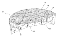
図1は、本発明の技術分野であるケーブルネットワークを利用した展開アンテナを概略的に示した斜視図である。図示したように、前記ケーブルネットワークを利用した展開アンテナ100には、前面ネット110と後面ネット120とが前後に位置し、テンションタイ130が前面ネット110のノードと、それに対応する後面ネット120のノードとを接続する。
FIG. 1 is a perspective view schematically showing a deployable antenna using a cable network which is a technical field of the present invention. As shown in the figure, the
このようなケーブル構造物の周りに円周トラス140が存在し、ケーブルネットワークを支持することにより、1つの構造物をなしたものを見せている。最終的に、導電性メッシュ150を前面ネット形状に沿って付着し、所望の形の反射面を形成するようになる。また、円周トラス140は、折り畳むことのできる形を持っており、小さなサイズに折り畳むことができ、このとき、ケーブルネットワーク及びメッシュ150も共に折り畳まれて小さなサイズにすることができる。このようなアンテナは、宇宙に発射されて、宇宙空間で10メートルまたはそれ以上の直径を有する円形開口面の放物面アンテナとなる。
A
ここで、テンションタイ130の役割を詳しく説明すれば、次のとおりである。テンションタイは、前面ネットと後面ネットとのノードを接続するが、各テンションタイが存在する座標における放物面上の高さに合うように、その長さが定められるため、前面ネットと後面ネットとは対称的に放物面を作るようになる。ここで、反射面は、必要に応じて放物面ではなく、平面や球面になり得る。理論的には、このようにアンテナを構成したとき、テンションタイの長さを調節する必要はないが、ケーブルの長さ誤差、各ケーブル接続地点誤差、アンテナ全体の構造的形状誤差等のため、テンションタイの長さを調節する必要が生じる。
Here, the role of the
また、テンションタイの長さがあまり長くないので、テンションタイの製作誤差による長さ調節はそれほど要求されないが、全体構造的な形状誤差によるテンションタイの長さ調節の必要性が重要となり得る。このようなテンションタイの個数は、主にアンテナの大きさに左右されるが、10メートルアンテナの場合、数百個のテンションタイを必要とする。このようなテンションタイの長さを調節しようとすれば、多くの時間と人数が必要となり、これは、製品の価格上昇を招く。 Further, since the length of the tension tie is not so long, the length adjustment due to the manufacturing error of the tension tie is not so required, but the necessity of adjusting the length of the tension tie due to the overall structural shape error may be important. The number of such tension ties depends mainly on the size of the antenna, but in the case of a 10 meter antenna, several hundred tension ties are required. In order to adjust the length of such a tension tie, a lot of time and people are required, which leads to an increase in the price of the product.
つまり、テンションタイの長さ調節は容易でなければならず、かつ、速かに行えるべきであり、テンションタイの長さ調節量は、反射面の測定によって与えられるが、所望どおりに長さを調節したということを確認するためには、作業者が調節した長さの量を目で直ちに把握することができなければならない。 In other words, tension tie length adjustment should be easy and should be done quickly, and the tension tie length adjustment is given by the measurement of the reflective surface, but the length can be adjusted as desired. In order to confirm that it has been adjusted, the operator must be able to immediately grasp the amount of length adjusted by the operator.
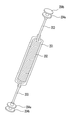
図2は、従来技術に係るテンションタイの構造を概略的に示した斜視図であって、Astro Aerospace Corporationの米国公開特許5,680,145に掲載されたテンションタイを示したものである。前記テンションタイは、ばね202と、ばねケース201と、テンションタイケーブル203と、テンションタイを前面ネットと後面ネットとに接続するための部品204a、204bとを備える。
FIG. 2 is a perspective view schematically showing a structure of a tension tie according to the prior art, and shows a tension tie described in US Patent No. 5,680,145 of Astro Aerospace Corporation. The tension tie includes a
そして、前記従来技術に係る発明では、テンションタイの長さを調節する方法に関する記載がない。このような構造では、テンションタイの長さ誤差分だけばねの長さが伸びるか、または縮められて、自動的にテンションタイの長さが調節されるようにしたものと見える。しかし、このような方法は、アンテナ全体のうち、局部的にいくつのテンションタイの長さが誤っており、これを修正しなければならないとき、自動で反映されて効果的であり得るが、全体的に全てのテンションタイの長さが連続的に誤っている場合、これを反映できないという問題を有している。すなわち、テンションタイが作り出す前面ネットの反射面が正確な放物面ではなく、言い替えれば、曲率が全般的に誤った、曲面が形成されたときは、このような誤差を自動で修正することができなくなるという短所がある。また、自動で面が形成されたとしても、特定部位で人為的に修正しなければならない場合、これを行うことができないという問題を有している。 And in the invention which concerns on the said prior art, there is no description regarding the method of adjusting the length of a tension tie. In such a structure, it appears that the length of the spring is extended or reduced by the length error of the tension tie so that the length of the tension tie is automatically adjusted. However, such a method may be effective automatically reflected when the length of the tension tie locally in the entire antenna is incorrect and must be corrected. In particular, when the lengths of all the tension ties are continuously incorrect, there is a problem that this cannot be reflected. In other words, when the reflection surface of the front net created by the tension tie is not an accurate paraboloid, in other words, when a curved surface is formed with a generally incorrect curvature, such errors can be automatically corrected. There is a disadvantage that it can not be done. Moreover, even if the surface is automatically formed, there is a problem that this cannot be performed when it is necessary to artificially correct the specific part.
つまり、前記ばねに一定のテンションが発生したまま組み立てられ、アンテナが折り畳まれた状態では、テンションが0になり、そのばねとケースとの間の摩擦が存在する。また、アンテナを折り畳んで展開するとき、テンションタイに引張力が加えられ始め、これは、ばねとケースとの間の摩擦力を克服してこそ組み立てるときの長さ、すなわち、最終長さに伸びて所望の反射面を形成するようになるが、その引張力が小さい場合、ばねとケースとの間の摩擦力を十分に勝つことができないこともあり、この場合、テンションタイの最終長さから外れる可能性があるという問題を有している。 That is, in a state where the spring is assembled with a certain tension and the antenna is folded, the tension becomes zero, and there is friction between the spring and the case. In addition, when the antenna is folded and unfolded, a tension force starts to be applied to the tension tie, which extends to the length when assembled when the friction force between the spring and the case is overcome, that is, the final length. However, if the tensile force is small, the frictional force between the spring and the case may not be sufficiently overcome. There is a problem that it may come off.
本発明は、上記のような従来技術の問題を解決するために提案されたものであって、その目的は、ケーブルネットワーク構造物で作った展開アンテナにおいて、反射面を形成するテンションタイの長さを調節できるようにするために、テンションタイの長さを一定間隔ずつ調節できるようにし、調節した長さを目で直ちに確認することができるようにして、所望の長さに調節できるようにすることにより、大型展開アンテナの製作が容易で、かつ、正確な表面を製作できるケーブルネットワークアンテナのテンションタイ長さ調節装置を提供することにある。 The present invention has been proposed in order to solve the above-described problems of the prior art, and its purpose is to provide a length of a tension tie that forms a reflective surface in a deployable antenna made of a cable network structure. In order to be able to adjust the length of the tension tie, the length of the tension tie can be adjusted at regular intervals, and the adjusted length can be immediately confirmed by the eye so that it can be adjusted to the desired length. Accordingly, it is an object of the present invention to provide a tension tie length adjusting device for a cable network antenna, which can easily manufacture a large deployable antenna and can manufacture an accurate surface.
そこで、上記の目的を達成するための本発明のケーブルネットワークアンテナのテンション長さ調節装置は、ケーブルネットワーク構造物の展開型アンテナに装着されるテンションタイ長さ調節装置であって、ケーブルが接続され、固定孔が形成されたケーブル固定部と、該ケーブル固定部の外周に結合され、複数の固定孔が形成された固定ケースと、前記ケーブル固定部内に位置し、ケーブル固定部の固定孔及び固定ケースの固定孔を通過してケーブル固定部及び固定ケースの長さ方向への移動を防止する固定部とを備えることを特徴とする。 Therefore, the cable network antenna tension length adjusting device of the present invention for achieving the above object is a tension tie length adjusting device mounted on a deployable antenna of a cable network structure, to which a cable is connected. A cable fixing part formed with a fixing hole, a fixing case coupled to the outer periphery of the cable fixing part and formed with a plurality of fixing holes, and a fixing hole and fixing of the cable fixing part located in the cable fixing part A cable fixing portion that passes through the fixing hole of the case and a fixing portion that prevents the fixing case from moving in the length direction are provided.
また、前記固定部が、第1の実施形態として、前記ケーブル固定部の内周面から固定孔に向けて突出する固定部材移動ガイドと、該固定部材移動ガイドの内部に挿入され、ケーブル固定部の固定孔及び固定ケースの固定孔を通過する固定部材と、該固定部材の下部に装着され、固定部材移動ガイドに支持されて固定部材をケーブル固定部の固定孔及び固定ケースの固定孔に向けるように弾性力を提供する弾性部材とを備える。 Further, as the first embodiment, the fixing portion is inserted into the fixing member moving guide, the fixing member moving guide protruding from the inner peripheral surface of the cable fixing portion toward the fixing hole, and the cable fixing portion. A fixing member that passes through the fixing hole of the fixing case and the fixing hole of the fixing case, and a fixing member that is attached to the lower portion of the fixing member and is supported by the fixing member moving guide and directs the fixing member toward the fixing hole of the cable fixing portion and the fixing hole of the fixing case And an elastic member that provides an elastic force.
また、前記固定部が、第2の実施形態として、前記ケーブル固定部の内周面から支持され、固定孔に向けて突出する板ばねと、該板ばねに支持され、ケーブル固定部の固定孔及び固定ケースの固定孔を通過する固定部材とを備える。 Further, as the second embodiment, the fixing portion is supported from the inner peripheral surface of the cable fixing portion and protrudes toward the fixing hole, and is supported by the leaf spring, and the fixing hole of the cable fixing portion. And a fixing member that passes through the fixing hole of the fixing case.
そして、前記板ばねが、アーチ型板ばね及び球面型板ばねから選択される。 The leaf spring is selected from an arch shaped leaf spring and a spherical leaf spring.
また、前記板ばねは、固定部材挿入孔が形成され、前記固定部材は、前記板ばねの固定部材挿入孔に挿入される。 The leaf spring is formed with a fixing member insertion hole, and the fixing member is inserted into the fixing member insertion hole of the leaf spring.
また、前記固定ケースの断面が、円形及び四角形から選択される。 The cross section of the fixed case is selected from a circle and a quadrangle.
そして、前記固定ケースの複数の固定孔が、長さ方向に対してジグザグ方向に形成することができ、斜線方向に形成することもできる。 The plurality of fixing holes of the fixing case can be formed in the zigzag direction with respect to the length direction, or can be formed in the oblique direction.
本発明によるテンションタイ長さ調節装置を使用することになると、所望どおりにテンションタイの長さを正確に調節することができ、長さ調節方法も容易であり、作業時間が減って製作単価も減少するようになり、テンションタイ長さ調節間隔を決定するケースを交替することにより、テンションタイの長さを調節する精密度と総調節可能量を異にして種々の場合に対処できるだけでなく、所望の長さに固定された状態で折り畳んで展開されるので、展開されたとき、最終長さを常に維持することができるケーブルネットワークアンテナのテンションタイ長さ調節装置を提供する効果を有する。 When the tension tie length adjusting device according to the present invention is used, the length of the tension tie can be accurately adjusted as desired, the length adjusting method is easy, the working time is reduced, and the production unit cost is also reduced. By changing the case for determining the tension tie length adjustment interval, it is possible to cope with various cases with different precision and total adjustable amount for adjusting the tension tie length, Since it is folded and unfolded while being fixed to a desired length, it has the effect of providing a tension tie length adjusting device for a cable network antenna that can always maintain the final length when unfolded.
以下、本発明に係るケーブルネットワークアンテナのテンションタイ長さ調節装置の好ましい具体例に対する構成、機能、及び効果について詳細に説明する。 Hereinafter, the configuration, function, and effect of a preferred embodiment of the tension tie length adjusting device for a cable network antenna according to the present invention will be described in detail.
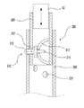
図3は、本発明の第1の実施形態に係るケーブルネットワークアンテナのテンションタイ長さ調節装置を概略的に示した部分断面図である。図示されているように、本発明に係るケーブルネットワークアンテナのテンションタイ長さ調節装置300は、固定部310と、ケーブル固定部320と、固定ケース330とを備える。
FIG. 3 is a partial cross-sectional view schematically showing a tension tie length adjusting device for a cable network antenna according to the first embodiment of the present invention. As illustrated, the tension tie
前記ケーブル固定部320は、一端にケーブル10が接続され、固定孔が形成される。そして、前記固定ケースは、ケーブル固定部320の外周に結合され、前記ケーブル固定部320の固定孔に対応する固定孔が複数個形成される。そして、前記固定部310は、前記ケーブル固定部320の内部に位置し、ケーブル固定部の固定孔及び固定ケース330の固定孔を通過してケーブル固定部及び固定ケースの長さ方向への移動を防止するためのものである。
The
より具体的に、前記固定部310の第1の実施形態は、図3に示すように、固定部材311と、固定部材移動ガイド321と、弾性部材313とを備えてなる。そして、前記固定部材移動ガイド321は、前記ケーブル固定部320の内周面から固定孔に向けて突出し、前記固定部材311は、前記固定部材移動ガイド321の内部に挿入され、ケーブル固定部320の固定孔及び固定ケース330の固定孔を通過する。このとき、前記弾性部材313は、前記固定部材の下部に装着され、固定部材移動ガイドに支持されて固定部材をケーブル固定部の固定孔及び固定ケースの固定孔に向けるように弾性力を提供する。そして、前記第1の実施形態に係る固定部310の弾性部材は、コイルばねからなる。
More specifically, the first embodiment of the fixing
また、前記固定部材311は、支持板312及びガイドピン314を備え、前記支持板312は、弾性部材313の挿入結合時、それを支持し、ガイドピン314は、前記固定部材移動ガイド321に挿入される。
The fixing
図4は、本発明の第2の実施形態に係るケーブルネットワークアンテナのテンションタイ長さ調節装置を概略的に示した部分断面図である。図示されているように、前記固定部310は、板ばね313′及び固定部材311を備える。前記固定部材は、図3において詳述したとおりであり、前記板ばね313′は、前記ケーブル固定部の内周面から支持され、固定孔に向けて突出する。また、前記板ばね313′は、固定部材挿入孔が形成され、前記固定部材310は、板ばね313′の挿入孔に挿入されて支持される。
FIG. 4 is a partial cross-sectional view schematically illustrating a tension tie length adjusting device for a cable network antenna according to a second embodiment of the present invention. As shown, the fixing
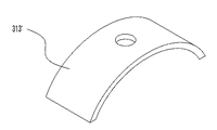
そして、前記板ばねは、図5Aに示すように、アーチ型板ばね313′で実現することができ、図5Bに示すように、球面型板ばね313″で実現することもできる。
The leaf spring can be realized by an
また、前記板ばねは、固定部材装着溝が形成され、前記固定部材は、前記板ばねの固定部材装着溝に挿入される。 Further, the leaf spring is formed with a fixing member mounting groove, and the fixing member is inserted into the fixing member mounting groove of the leaf spring.
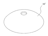
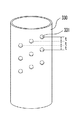
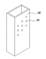
図6Aは、本発明に係るテンションタイ長さ調節装置の固定ケースの第1の実施形態を概略的に示した斜視図であり、図6Bは、本発明に係るテンションタイ長さ調節装置の固定ケースの第2の実施形態を概略的に示した斜視図である。 FIG. 6A is a perspective view schematically showing a first embodiment of a fixing case of a tension tie length adjusting device according to the present invention, and FIG. 6B is a fixing of the tension tie length adjusting device according to the present invention. It is the perspective view which showed schematically 2nd Embodiment of the case.
図示されているように、前記固定ケースの断面は、ケーブル10の形状によって円形からなることができ、四角形からなることもできる。また、前記ケーブル10は、上下に動き、テンションタイの全体長さが変わるようにする部分であり、ケーブル固定部320に固定される。
As shown in the figure, the cross section of the fixed case may be a circle or a rectangle depending on the shape of the
また、前記固定ケースの複数の固定孔331は、長さ方向に対して一定間隔tに沿ってジグザグ方向に形成することができ、斜線方向に形成することもできる。
In addition, the plurality of fixing
例えば、0.5mmずつテンションタイの長さを減らさなければならない場合、前記固定孔331は、縦方向に0.5mmずつ離れるように形成すればよい。このとき、前記固定孔の直径が0.5mmより小さければ、長さ方向に一直線に配列することができるが、現実的に孔の大きさが0.5mmより小さいことはあまりないため、図示されているように、斜線方向に配列するか、またはジグザグ形態に孔を配列すれば、小さな間隔で孔を開けることができる。
For example, when it is necessary to reduce the length of the tension tie by 0.5 mm, the fixing
反射板の地点によって、またはある理由によってテンションタイの長さ調節間隔が特定間隔よりさらに精密で、調節量が少ない場合があり得るし、調節間隔が大きく、総調節可能量が多い場合があり得るであろう。このような場合、固定孔331の間隔が互いに異なるように形成されている固定ケース330を用意し、必要に応じて交替して使用することもできる。
Depending on the location of the reflector or for some reason, the tension tie length adjustment interval may be more precise than the specific interval and the adjustment amount may be less, or the adjustment interval may be larger and the total adjustment amount may be greater. Will. In such a case, it is possible to prepare fixed
このようになされることにしたがって、テンションタイの長さは、固定部310を前記ケースの所望の孔に入れることで調節することができる。具体的に、固定孔から他の固定孔に移動する原理は、次のとおりである。前記固定部材311を細い棒等で押し入れて、固定孔から離脱されるようにした後、ケーブル固定部320を所望の位置に移動させ、固定部材は、ばねの復元力でさらに固定孔に挿入されて位置が調節される。
Accordingly, the length of the tension tie can be adjusted by inserting the fixing
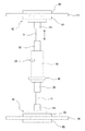
図7は、本発明に係るケーブルネットワークが組み立てられたケーブルネットワークアンテナのテンションタイ長さ調節装置を概略的に示した構成図である。図示されているように、前記テンションタイ固定ケーブル10は、テンションタイケーブルの外面付着装置421と内面付着装置422とによって前面ネット110に付着され、テンションタイ固定ケーブル10は、同様な方法によって後面ネット120に付着されている。テンションタイ長さ調節装置の方向が図7に示すように反対に装着されても差し支えない。また、前記テンションタイ固定ケーブル10は、テンションタイケーブル固定ピン340とテンションタイ固定ケーブル固定装置350とによって固定されるが、具体的な固定方法は、他の方法を使用しても差し支えない。そして、片側をテンションタイ固定ケーブルで構成せずに、両側をテンションタイ長さ調節ケーブルで構成することもできる。
FIG. 7 is a block diagram schematically illustrating a tension tie length adjusting device for a cable network antenna in which a cable network according to the present invention is assembled. As shown in the drawing, the tension
以上で説明した本発明は、前述した実施形態及び添付した図面に限定されるものではなく、本発明の技術的思想を逸脱しない範囲内で様々な置換及び変更が可能であるということが、本発明の属する技術分野における通常の知識を有した者にとって明白であろう。 The present invention described above is not limited to the above-described embodiments and the accompanying drawings, and various replacements and modifications can be made without departing from the technical idea of the present invention. It will be apparent to those skilled in the art to which the invention belongs.
100A テンションタイ長さ調節ケーブル
100B テンションタイ固定ケーブル
110 前面ネット
120 後面ネット
300 テンションタイ長さ調節装置
310 固定部
311 固定部材
312 支持板
313 弾性部材
314 ガイドピン
320 ケーブル固定部
321 固定部材移動ガイド
330 固定ケース
331 固定孔
100A Tension tie length adjusting cable 100B Tension
Claims (8)
ケーブルが接続され、固定孔が形成されたケーブル固定部と、
該ケーブル固定部の外周に結合され、複数の固定孔が形成された固定ケースと、
前記ケーブル固定部内に位置し、前記ケーブル固定部の固定孔及び前記固定ケースの固定孔を通過して前記ケーブル固定部及び前記固定ケースの長さ方向への移動を防止する固定部とを備え、
前記固定ケースの複数の固定孔は、前記固定ケースの長さ方向に隣り合う2つの前記固定ケースの固定孔の間隔が互いに異なることを特徴とするケーブルネットワークアンテナのテンションタイ長さ調節装置。 A tension tie length adjusting device attached to a deployable antenna of a cable network structure used in outer space ,
A cable fixing part in which a cable is connected and a fixing hole is formed;
A fixing case coupled to the outer periphery of the cable fixing portion and having a plurality of fixing holes;
The positioned cable fixing portion, and a fixing portion to prevent movement of the passes through the fixing hole and the fixing hole of the fixing casing of the cable fixing portion of the cable fixing portion and the fixed case the length direction,
The tension tie length adjusting device for a cable network antenna , wherein the plurality of fixing holes of the fixing case have different intervals between the fixing holes of two fixing cases adjacent to each other in the length direction of the fixing case .
前記ケーブル固定部の内周面から固定孔に向けて突出する固定部材移動ガイドと、
該固定部材移動ガイドの内部に挿入され、ケーブル固定部の固定孔及び固定ケースの固
定孔を通過する固定部材と、
該固定部材の下部に装着され、固定部材移動ガイドに支持されて固定部材をケーブル固
定部の固定孔及び固定ケースの固定孔に向けるように弾性力を提供する弾性部材と、
を備えることを特徴とする請求項1に記載のケーブルネットワークアンテナのテンショ
ンタイ長さ調節装置。 The fixing part is
A fixing member moving guide protruding from the inner peripheral surface of the cable fixing portion toward the fixing hole;
A fixing member inserted into the fixing member moving guide and passing through the fixing hole of the cable fixing portion and the fixing hole of the fixing case;
An elastic member attached to a lower portion of the fixing member and supported by a fixing member moving guide to provide an elastic force so as to direct the fixing member toward the fixing hole of the cable fixing portion and the fixing hole of the fixing case;
The tension tie length adjusting device for a cable network antenna according to claim 1.
前記ケーブル固定部の内周面から支持され、固定孔に向けて突出する板ばねと、
該板ばねに支持され、ケーブル固定部の固定孔及び固定ケースの固定孔を通過する固定
部材と、
を備えることを特徴とする請求項1に記載のケーブルネットワークアンテナのテンショ
ンタイ長さ調節装置。 The fixing part is
A leaf spring supported from the inner peripheral surface of the cable fixing portion and protruding toward the fixing hole;
A fixing member supported by the leaf spring and passing through the fixing hole of the cable fixing portion and the fixing hole of the fixing case;
The tension tie length adjusting device for a cable network antenna according to claim 1.
項3に記載のケーブルネットワークアンテナのテンションタイ長さ調節装置。 4. The tension tie length adjusting device for a cable network antenna according to claim 3, wherein the leaf spring is selected from an arch shaped leaf spring and a spherical shaped leaf spring.
入孔に挿入されることを特徴とする請求項4に記載のケーブルネットワークアンテナのテ
ンションタイ長さ調節装置。 5. The tension tie length adjustment of a cable network antenna according to claim 4, wherein the leaf spring is formed with a fixing member insertion hole, and the fixing member is inserted into the fixing member insertion hole of the leaf spring. apparatus.
記載のケーブルネットワークアンテナのテンションタイ長さ調節装置。 2. The tension tie length adjusting device for a cable network antenna according to claim 1, wherein a cross section of the fixing case is selected from a circle and a quadrangle.
特徴とする請求項1に記載のケーブルネットワークアンテナのテンションタイ長さ調節装
置。 The tension tie length adjusting device for a cable network antenna according to claim 1, wherein the plurality of fixing holes of the fixing case are formed in a zigzag direction with respect to the length direction.
とする請求項1に記載のケーブルネットワークアンテナのテンションタイ長さ調節装置。 The tension tie length adjusting device for a cable network antenna according to claim 1, wherein the plurality of fixing holes of the fixing case are formed in a diagonal direction with respect to the length direction.
Applications Claiming Priority (2)
| Application Number | Priority Date | Filing Date | Title |
|---|---|---|---|
| KR10-2009-0086526 | 2009-09-14 | ||
| KR1020090086526A KR101214545B1 (en) | 2009-09-14 | 2009-09-14 | Length adjusting device for cable-network antenna's tension-tie |
Publications (2)
| Publication Number | Publication Date |
|---|---|
| JP2011061763A JP2011061763A (en) | 2011-03-24 |
| JP5073790B2 true JP5073790B2 (en) | 2012-11-14 |
Family
ID=43729039
Family Applications (1)
| Application Number | Title | Priority Date | Filing Date |
|---|---|---|---|
| JP2010164185A Expired - Fee Related JP5073790B2 (en) | 2009-09-14 | 2010-07-21 | Cable network antenna tension tie length adjustment device |
Country Status (3)
| Country | Link |
|---|---|
| US (1) | US8066445B2 (en) |
| JP (1) | JP5073790B2 (en) |
| KR (1) | KR101214545B1 (en) |
Families Citing this family (8)
| Publication number | Priority date | Publication date | Assignee | Title |
|---|---|---|---|---|
| US9070309B2 (en) * | 2011-09-08 | 2015-06-30 | Robert D. Proctor | Flagpole system providing half-mast display mode |
| US20130330118A1 (en) * | 2012-06-11 | 2013-12-12 | Trace Eugene Van Dyne | Cable-Actuated Latching Mechanism |
| KR102337587B1 (en) * | 2015-04-15 | 2021-12-09 | 엘에스일렉트릭(주) | Operating handle apparatus of circuit breaker |
| US10806287B2 (en) * | 2017-05-24 | 2020-10-20 | United States Postal Service | Anti-tearing retractable arm for a collection box |
| US10727605B2 (en) * | 2018-09-05 | 2020-07-28 | Eagle Technology, Llc | High operational frequency fixed mesh antenna reflector |
| WO2022109575A1 (en) * | 2020-11-17 | 2022-05-27 | L'garde, Inc. | Light weight, low stowed volume, space deployable batten-less truss |
| US12549126B2 (en) | 2021-11-12 | 2026-02-10 | L'garde, Inc. | Lightweight, low stow volume, deployable solar concentrator for space applications |
| CN119362022B (en) * | 2024-10-31 | 2026-02-06 | 西安电子科技大学 | A large cable net antenna profile active adjustment device and adjustment method |
Family Cites Families (7)
| Publication number | Priority date | Publication date | Assignee | Title |
|---|---|---|---|---|
| US3662436A (en) * | 1970-12-28 | 1972-05-16 | Joslyn Mfg & Supply Co | Screw anchor |
| US5680145A (en) * | 1994-03-16 | 1997-10-21 | Astro Aerospace Corporation | Light-weight reflector for concentrating radiation |
| JP3022525B1 (en) * | 1998-11-16 | 2000-03-21 | 日本電気株式会社 | Wire winding type extension device |
| JP3868689B2 (en) | 2000-01-17 | 2007-01-17 | 三菱電機株式会社 | Expansion membrane antenna for space |
| KR100612749B1 (en) | 2004-06-18 | 2006-08-21 | 현대자동차주식회사 | Removal aid for muffler hanger rod |
| JP5053053B2 (en) * | 2007-11-21 | 2012-10-17 | Dxアンテナ株式会社 | Antenna device |
| US7712478B2 (en) * | 2008-04-07 | 2010-05-11 | Cowboylogic, Llc | Ergonomic crutch |
-
2009
- 2009-09-14 KR KR1020090086526A patent/KR101214545B1/en not_active Expired - Fee Related
-
2010
- 2010-06-18 US US12/818,208 patent/US8066445B2/en not_active Expired - Fee Related
- 2010-07-21 JP JP2010164185A patent/JP5073790B2/en not_active Expired - Fee Related
Also Published As
| Publication number | Publication date |
|---|---|
| KR101214545B1 (en) | 2012-12-24 |
| KR20110028894A (en) | 2011-03-22 |
| US20110061210A1 (en) | 2011-03-17 |
| JP2011061763A (en) | 2011-03-24 |
| US8066445B2 (en) | 2011-11-29 |
Similar Documents
| Publication | Publication Date | Title |
|---|---|---|
| JP5073790B2 (en) | Cable network antenna tension tie length adjustment device | |
| US9484636B2 (en) | Mesh reflector with truss structure | |
| CN104518287B (en) | Varifocal reflection surface system based on ring rib post cable net structure | |
| US9405091B2 (en) | Parabolic reflector | |
| JP5862384B2 (en) | Main mirror support structure and telescope device | |
| CZ20031077A3 (en) | Antenna mast and device for adjusting an antenna orientation | |
| CN112018487B (en) | Deployable helical antenna, communication system, radar and electronic countermeasure system | |
| US20120044125A1 (en) | Cable network antenna and the producing method thereof | |
| CN208189119U (en) | Steel construction for large-scale curved LED screen | |
| CN101635390B (en) | Final-assembly die with truss type spatial structure | |
| CN108335640A (en) | Steel construction and its layout method for large-scale curved LED screen | |
| US20190186135A1 (en) | Connector system for trusses | |
| JP2001318301A (en) | Optical member support device | |
| CN111585037B (en) | Cable section cutting and networking method of mesh antenna | |
| RU2276823C2 (en) | Method for manufacturing large-size scanned reflectors and curvilinear reflector surface shaping device | |
| US8359760B2 (en) | Form aligner for concrete formwork | |
| CN218160837U (en) | Honeycomb reflector structure | |
| RU2674386C2 (en) | Method for making large-dimensional transformable reflector | |
| JP3422404B2 (en) | Spherical approximation frame structure | |
| JP2001020145A (en) | Expansion type eye board | |
| RU2344524C1 (en) | Method of large reflector manufacturing | |
| CN107968243B (en) | A kind of assembly of feed and angular adjustment apparatus | |
| JPH04132402A (en) | Expansion mesh antenna | |
| EP3621152B1 (en) | High operational frequency fixed mesh antenna reflector | |
| EP2393157A1 (en) | External antenna for television |
Legal Events
| Date | Code | Title | Description |
|---|---|---|---|
| A977 | Report on retrieval |
Free format text: JAPANESE INTERMEDIATE CODE: A971007 Effective date: 20120309 |
|
| A131 | Notification of reasons for refusal |
Free format text: JAPANESE INTERMEDIATE CODE: A131 Effective date: 20120406 |
|
| A521 | Request for written amendment filed |
Free format text: JAPANESE INTERMEDIATE CODE: A523 Effective date: 20120706 |
|
| TRDD | Decision of grant or rejection written | ||
| A01 | Written decision to grant a patent or to grant a registration (utility model) |
Free format text: JAPANESE INTERMEDIATE CODE: A01 Effective date: 20120727 |
|
| A01 | Written decision to grant a patent or to grant a registration (utility model) |
Free format text: JAPANESE INTERMEDIATE CODE: A01 |
|
| A61 | First payment of annual fees (during grant procedure) |
Free format text: JAPANESE INTERMEDIATE CODE: A61 Effective date: 20120822 |
|
| R150 | Certificate of patent or registration of utility model |
Free format text: JAPANESE INTERMEDIATE CODE: R150 |
|
| FPAY | Renewal fee payment (event date is renewal date of database) |
Free format text: PAYMENT UNTIL: 20150831 Year of fee payment: 3 |
|
| LAPS | Cancellation because of no payment of annual fees |