JP5073732B2 - Ballot paper reader - Google Patents
Ballot paper reader Download PDFInfo
- Publication number
- JP5073732B2 JP5073732B2 JP2009253669A JP2009253669A JP5073732B2 JP 5073732 B2 JP5073732 B2 JP 5073732B2 JP 2009253669 A JP2009253669 A JP 2009253669A JP 2009253669 A JP2009253669 A JP 2009253669A JP 5073732 B2 JP5073732 B2 JP 5073732B2
- Authority
- JP
- Japan
- Prior art keywords
- voting paper
- voting
- conveyance path
- paper
- ballot
- Prior art date
- Legal status (The legal status is an assumption and is not a legal conclusion. Google has not performed a legal analysis and makes no representation as to the accuracy of the status listed.)
- Active
Links
- 238000003384 imaging method Methods 0.000 claims description 62
- 230000010365 information processing Effects 0.000 claims description 25
- 230000032258 transport Effects 0.000 description 25
- 238000010586 diagram Methods 0.000 description 5
- 238000000034 method Methods 0.000 description 5
- 230000002093 peripheral effect Effects 0.000 description 2
- 238000000605 extraction Methods 0.000 description 1
- 238000011144 upstream manufacturing Methods 0.000 description 1
Images


Landscapes
- Facsimile Scanning Arrangements (AREA)
- Character Input (AREA)
- Image Input (AREA)
- Facsimiles In General (AREA)
Description
本発明は、投票用紙の読取装置に関するものである。 The present invention relates to a ballot paper reader.
従来用いられていたこの種の投票用紙の読取装置としては、例えば下記の特許文献1等に示されている構成が用いられている。すなわち、従来の読取装置では、投票用紙が搬送される搬送路に対向して撮像手段が配置されている。撮像手段には光源部及び撮像部が含まれており、光源部から投票用紙に対して撮像光が照射されるとともに、投票用紙の片側の端面で反射された撮像光が撮像部で受光されることで、投票用紙の片面の画像情報が生成される。そして、この画像情報に基づいて、投票用紙に付されている記入枠が検出されるとともに、記入枠の内側に記載された例えば候補者や政党等の記載内容が読み取られ、記載内容毎に投票用紙が自動的に分類される。
As this type of voting paper reading device that has been used in the past, for example, the configuration shown in
上記のような従来の投票用紙の読取装置では、投票用紙の片面の画像情報のみを取得する構成であるので、投票用紙の片面でしか記載内容の読み取りを行うことができない。このため、従来装置では、投票用紙を読取装置に投入する前に投票用紙の表裏を人手により揃える必要があり、利便性が低下している。 Since the conventional ballot paper reader as described above is configured to acquire only image information on one side of the ballot paper, the description content can be read only on one side of the ballot paper. For this reason, in the conventional apparatus, it is necessary to align the front and back of the voting paper by hand before putting the voting paper into the reading device, which reduces convenience.
本発明は、上記のような課題を解決するためになされたものであり、その目的は、投票用紙の表裏を予め揃える工程を不要にでき、利便性を向上できる投票用紙の読取装置を提供することである。 The present invention has been made to solve the above-described problems, and an object of the present invention is to provide a ballot paper reader that can eliminate the step of aligning the front and back of the ballot paper in advance and improve convenience. That is.
本発明に係る投票用紙の読取装置は、投票用紙が搬送される搬送路と、搬送路の搬送路表面に対向して配置された第1撮像手段と、搬送路の搬送路裏面に対向して配置された第2撮像手段と、第1及び第2撮像手段に接続された情報処理手段と、搬送路に接続された複数のスタッカとを備え、第1撮像手段は、投票用紙が搬送路を搬送される際に、投票用紙の第1端面を示す第1画像情報を生成し、第2撮像手段は、投票用紙が搬送路を搬送される際に、第1端面とは逆側の投票用紙の第2端面を示す第2画像情報を生成し、情報処理手段は、第1及び第2撮像手段からの第1及び第2画像情報に基づいて、第1及び第2端面のいずれか一方に付された投票用紙の記入枠を検出し、記入枠内に書き込まれた記載内容を読み取るとともに、投票用紙の表裏方向及び天地方向の向きを識別し、投票用紙の記載内容毎及び向き毎に、投票用紙を異なるスタッカに搬送させる。 A voting paper reading device according to the present invention is provided with a conveyance path for conveying voting paper, a first imaging unit disposed opposite to a conveyance path surface of the conveyance path, and a conveyance path rear surface of the conveyance path. A second imaging unit disposed; an information processing unit connected to the first and second imaging units; and a plurality of stackers connected to the conveyance path. The first image information indicating the first end surface of the voting paper is generated when the voting paper is conveyed, and the second imaging unit is configured so that the voting paper on the side opposite to the first end surface when the voting paper is conveyed on the conveyance path. 2nd image information which shows the 2nd end surface of this is produced | generated, and an information processing means is based on the 1st and 2nd image information from a 1st and 2nd imaging means, and either one of a 1st and 2nd end surface detecting the input frames of the given voting paper, with reading the description written in the entry box, voting Identify the front and back direction and vertical direction of the orientation of the paper, the content for each and every orientation according ballot to transport the ballot different stacker.
本発明の投票用紙の読取装置によれば、第1撮像手段は、投票用紙が搬送路を搬送される際に、投票用紙の第1端面を示す第1画像情報を生成し、第2撮像手段は、投票用紙が搬送路を搬送される際に、第1端面とは逆側の投票用紙の第2端面を示す第2画像情報を生成し、情報処理手段は、第1及び第2撮像手段からの第1及び第2画像情報に基づいて、第1及び第2端面のいずれか一方に付された投票用紙の記入枠を検出するとともに、記入枠内に書き込まれた記載内容を読み取るので、記入枠が付された端面の向きに拘わらず投票用紙の記載内容を読み取ることができる。これにより、投票用紙の表裏を予め揃える工程を不要にでき、利便性を向上できる。 According to the voting paper reading apparatus of the present invention, the first imaging means generates the first image information indicating the first end face of the voting paper when the voting paper is conveyed along the conveyance path, and the second imaging means. Generates the second image information indicating the second end face of the voting paper opposite to the first end face when the voting paper is conveyed on the conveyance path, and the information processing means includes the first and second imaging means. Based on the first and second image information from, so as to detect the entry frame of the ballot attached to either one of the first and second end faces, and to read the description content written in the entry frame, Regardless of the direction of the end face to which the entry frame is attached, it is possible to read the contents of the ballot. As a result, the process of aligning the front and back of the voting paper in advance can be eliminated, and convenience can be improved.
以下、本発明を実施するための形態について、図面を参照して説明する。
実施の形態1.
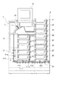
図1は、本発明の実施の形態1による投票用紙の読取装置を示す構成図である。図において、投票用紙の読取装置には、読取装置本体1と拡張スタッカユニット2とが設けられている。読取装置本体1には、ホッパ10、本体側搬送手段11、第1〜第5スタッカ12〜16、撮像ユニット17、及び表示手段18が設けられている。
Hereinafter, embodiments for carrying out the present invention will be described with reference to the drawings.
FIG. 1 is a block diagram showing a ballot paper reader according to
ホッパ10は、外部から投入された複数枚の投票用紙3が貯められるケースである。本体側搬送手段11は、複数の搬送ローラ11aから構成されており、ホッパ10から第1〜第5スタッカ12〜16まで搬送方向110に沿って投票用紙3を搬送する第1本体内搬送路111を形成している。また、本体側搬送手段11は、第1本体内搬送路111の中途位置111aから分離されるとともに、拡張スタッカユニット2に向けて投票用紙3を搬送する第2本体内搬送路112を形成している。撮像ユニット17は、後述のように投票用紙3の端面を示す画像情報を生成するものであり、搬送方向110に沿うホッパ10の下流かつ中途位置111aの上流に配置されている。表示手段18は、利用者に対する情報を表示するものである。
The
拡張スタッカユニット2は、読取装置本体1から分離可能な拡張ユニットである。拡張スタッカユニット2には、拡張側搬送手段20、及び第6〜第13スタッカ21〜28が設けられている。拡張側搬送手段20は、第2本体内搬送路112を通って拡張スタッカユニット2に搬送された投票用紙3を第6〜第13スタッカ21〜28まで搬送する拡張側搬送路200を形成している。
The
第1〜第13スタッカ12〜16,21〜28は、後述のように分類された投票用紙3がそれぞれ貯められるケースである。なお、この実施の形態では、1つの拡張スタッカユニット2が読取装置本体1に接続されている例を示しているが、必要とされるスタッカの数に応じて、複数の拡張スタッカユニット2が読取装置本体1に接続されてもよい。また、読取装置本体1から分離可能なものとして拡張スタッカユニット2を説明しているが、読取装置本体1と拡張スタッカユニット2とは互いに一体に設けられていてもよい。
The first to thirteenth stackers 12 to 16 and 21 to 28 are cases in which
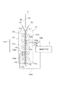
次に、図2は、図1の撮像ユニット17を示す構成図である。撮像ユニット17には、第1及び第2案内板170,171と、第1〜第3ローラ部172〜174と、第1及び第2撮像手段175,176と、第1及び第2対向ローラ177,178とが設けられている。
Next, FIG. 2 is a block diagram showing the
第1及び第2案内板170,171は、搬送方向110に沿って延在された板部材であり、第1本体内搬送路111を挟むように互いに対向して配置されている。これら第1及び第2案内板170,171は、投票用紙3が撮像ユニット17を通過する際に投票用紙3を案内するものである。なお、詳細には図示しないが、第1及び第2案内板170,171には、前述の第1〜第3ローラ部172〜174等が配置される各位置に開口部がそれぞれ設けられている。
The first and
第1ローラ部172は、第1及び第2案内板170,171の開口部を通して互いの外周面が接触するように第1本体内搬送路111を挟んで配置された一対のローラ172aから構成されている。第2及び第3ローラ部173,174も、第1ローラ部172と同様に一対のローラ173a,174aから構成されている。これら第1〜第3ローラ部172〜174は、搬送方向110に沿って互いに離間して配置されており、各ローラ172a〜174a間に進入された投票用紙3を搬送方向110に沿って送り出す(搬送する)ものである。すなわち、第1〜第3ローラ部172〜174は、本体側搬送手段11の一部を構成している。
The
ここで、第1案内板170が配置されている側の第1本体内搬送路111の一方の端面を搬送路表面113と呼び、第2案内板171が配置されている側の他方の端面を搬送路裏面114と呼ぶ。換言すると、投票用紙3が撮像ユニット17を通過する際に、投票用紙3の第1及び第2端面3a,3bが対向する第1本体内搬送路111の端面を、搬送路表面113及び搬送路裏面114と呼ぶ。後に詳しく説明するが、投票用紙3の向きに応じて、第1端面3aは投票用紙3の表面300及び裏面310(図3及び図4参照)のいずれか一方であり、第2端面3bは表面300及び裏面310の他方である。また、後に詳しく説明するが、投票用紙3の表裏方向及び天地方向の向きが互いに揃えられていない場合、投票用紙3の向きは4通り想定される(図5参照)。
Here, one end surface of the first in-
第1撮像手段175は、第1案内板170の開口部を通して搬送路表面113に対向するように第1ローラ部172と第2ローラ部173との間に配置されている。第1撮像手段175は、光源部175aと撮像部175bとを有しており、投票用紙3が撮像ユニット17を通過する際に投票用紙3の第1端面3aを示す第1画像情報175cを生成するものである。具体的には、投票用紙3が撮像ユニット17を通過する際に、投票用紙3の第1端面3aに対して光源部175aから撮像光が照射され、第1端面3aで反射された撮像光が撮像部175bで受光されることで、第1画像情報175cが生成される。
The first imaging means 175 is disposed between the
第1対向ローラ177は、第2案内板171の開口部を通して第1撮像手段175の撮像側端面に対向するように第1ローラ部172と第2ローラ部173との間に配置されている。この第1対向ローラ177は、その外周面と第1撮像手段175の撮像側端面との間に投票用紙3が進入された際に投票用紙3を搬送方向110に沿って送り出すように、第1撮像手段175の撮像側端面に近接して配置されている。
The first opposing
第2撮像手段176は、第2案内板171の開口部を通して搬送路裏面114に対向するように第2ローラ部173と第3ローラ部174との間に配置されている。すなわち、第2撮像手段176は、搬送方向110に沿う第1撮像手段175の下流に配置されており、第1撮像手段175に対して非対向とされている。第2撮像手段176は、前述の第1撮像手段175と同様に光源部176aと撮像部176bとを有しており、第1端面3aとは逆側の投票用紙3の第2端面3bを示す第2画像情報176cを生成するものである。
The
第2対向ローラ178は、第1案内板170の開口部を通して第2撮像手段176に対向するように第2ローラ部173と第3ローラ部174との間に配置されている。この第2対向ローラ178は、第1対向ローラ177と同様に、第2撮像手段176の撮像側端面に近接して配置されている。
The
第1及び第2撮像手段175,176には、情報処理手段4が接続されている。この情報処理手段4は、プログラム等の情報を記憶する記憶部と、この記憶部の情報に基づいて処理動作を行う演算部とを含むコンピュータから構成されている。詳細には、情報処理手段4は、読取装置本体1に内蔵されたコンピュータ、又は読取装置本体1とは別体に設けられたコンピュータと読取装置本体1に内蔵されたコンピュータとの組み合わせから構成されている。この情報処理手段4は、後述のように、第1及び第2撮像手段175,176からの第1及び第2画像情報175c,176cを処理するものである。
The information processing means 4 is connected to the first and second imaging means 175 and 176. The information processing means 4 is composed of a computer including a storage unit that stores information such as a program and an arithmetic unit that performs a processing operation based on the information stored in the storage unit. Specifically, the information processing means 4 is configured by a computer built in the reader
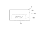
次に、図3は図2の投票用紙3を示す正面図であり、図4は図3の投票用紙3を示す背面図である。図3及び図4に示すように、投票用紙3は、長辺30及び短辺31を有する長方形に形成されている。この実施の形態の読取装置では、投票用紙3は、短辺31が搬送方向110に沿う向きで搬送される。図3に示すように、投票用紙3の表面300には、投票者が例えば候補者名や政党名等の記載内容301を記載すべき領域を区画する記入枠302が付されている。一方で、投票用紙3の裏面310には、記入枠302は付されていない。
3 is a front view showing the
前述の情報処理手段4は、第1及び第2撮像手段175,176からの第1及び第2画像情報175c,176cに基づいて、第1及び第2端面3a,3bのいずれか一方である表面300から記入枠302を検出するとともに、記入枠302内の記載内容301を読み取る。また、情報処理手段4は、本体側搬送手段11及び拡張側搬送手段20の動作を制御して、投票用紙3を記載内容301毎に異なるスタッカ12〜15,21〜28(図1参照)に搬送させる。なお、この実施の形態の読取装置では、第1〜第4スタッカ12〜15が第1候補者に割り当てられ、第6〜第9スタッカ21〜24が第2候補者に割り当てられ、第10〜第13スタッカ25〜28が第3候補者に割り当てられている。
The information processing means 4 is a surface that is one of the first and second end faces 3a and 3b based on the first and
また、情報処理手段4は、第1及び第2画像情報175c,176cに基づいて、第1及び第2端面3a,3bで記入枠302外に書込み(他事記載)が行われているか否かを判定する。なお、図示はしないが、投票用紙3には、周知のように例えば選挙内容や注意事項等の説明文等が予め付されている。上記の書込みとは、投票者等によって付加的に行われるものであり、予め付された説明文等以外のものである。情報処理手段4は、投票用紙3に書込みが行われていると判定した場合には、該投票用紙3を無効若しくは再検査が必要なものとしてリジェクトする。すなわち、情報処理手段4は、書込みが行われている投票用紙3を書込みが行われていない投票用紙3とは異なるスタッカ16に搬送させる。この実施の形態では、第5スタッカ16がリジェクト用として割り当てられている。
Further, the information processing means 4 determines whether or not writing (other matters are described) outside the
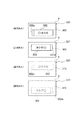
次に、図5は、図3の投票用紙3の向きの違いを示す説明図である。ホッパ10(図1参照)に複数の投票用紙3が投入される際に各投票用紙3の表裏方向及び天地方向の向きが揃えられていない場合、第1撮像手段175の前を通過するときの投票用紙3の向きは、図5に示すように4通り想定される。ここで、図5に示す各向きを、表天向き320、表地向き321、裏天向き322、及び裏地向き323と呼ぶ。
Next, FIG. 5 is an explanatory diagram showing a difference in orientation of the
表天向き320は、第1撮像手段175から見たときに、投票用紙3の表面300が正面を向いているとともに、記入枠302の上端302aが左側に位置している向きである。表地向き321とは、第1撮像手段175から見たときに、投票用紙3の表面300が正面を向いているとともに、記入枠302の上端302aが右側に位置している向きである。すなわち、表天向き320と表地向き321とは、記載内容301の文字列の方向、すなわち天地方向が反転している向きである。
The front-facing
裏天向き322は、第1撮像手段175から見たときに、投票用紙3の裏面310が正面を向いているとともに、記入枠302の上端302aが左側に位置している向きである。裏地向き323とは、第1撮像手段175から見たときに、投票用紙3の裏面310が正面を向いているとともに、記入枠302の上端302aが右側に位置している向きである。すなわち、これら裏天向き322及び裏地向き323は、前述の表天向き320及び表地向き321と比べて表裏方向が反転している向きである。
The back-facing
情報処理手段4は、第1及び第2画像情報175c,176cに基づいて記入枠302を検出するとともに記載内容301を読み取る際に、投票用紙3の表裏方向及び天地方向の向き(表天向き320、表地向き321、裏天向き322、及び裏地向き323)を識別し、投票用紙3の記載内容301及び向き320〜323毎に、投票用紙3を異なるスタッカ12〜15,21〜28に搬送させる。具体的には、記載内容301として第1候補者の名前が記入枠302内に記載されている場合、表天向き320の投票用紙3が第1スタッカ12に搬送され、表地向き321の投票用紙3が第2スタッカ13に搬送され、裏天向き322の投票用紙3が第3スタッカ14に搬送され、裏地向き323の投票用紙3が第4スタッカ15に搬送される。他の候補者に割り当てられているスタッカ21〜28に関しても同様である。
When the information processing means 4 detects the
次に、図6は、図2の情報処理手段4の搬送先判定動作を示すフローチャートである。図において、第1及び第2撮像手段175,176からの第1及び第2画像情報175c,176cが入力されると、第1画像情報175cが示す第1端面3aと第2画像情報176cが示す第2端面3bとのどちらから記入枠302が検出されるかが判定されることで、投票用紙3の表裏方向の向きが識別される(ステップS1)。このとき、第1端面3aから記入枠302が検出されると、投票用紙3の向きが表天向き320又は表地向き321であると識別され、第2端面3bから記入枠302が検出されると、投票用紙3の向きが裏天向き322又は裏地向き323であると識別される。
Next, FIG. 6 is a flowchart showing the transport destination determination operation of the information processing means 4 in FIG. In the figure, when the first and
その次に、検出された記入枠302内からの記載内容301の読み取ることができるか否かが判定され(ステップS2)、読み取ることができると判定された場合には、記載内容301が読み取られるとともに(ステップS3)、記載内容301の文字の向きから投票用紙3の天地方向の向きが識別される(ステップS4)。この時点で、投票用紙3の向きが、表天向き320、表地向き321、裏天向き322、及び裏地向き323のいずれであるかが識別される。
Next, it is determined whether or not the
その次に、第1及び第2画像情報175c,176cに基づいて、記入枠302の外に書込み(他記載)があるか否かが判定され(ステップS5)、書込みが無いと判定された場合に、記載内容301及び向き320〜323に応じたスタッカ12〜15,21〜28に投票用紙3が搬送されて(ステップS6)、搬送先判定動作が終了される。
Next, based on the first and
一方、記載内容301の読取判定時(ステップS2)に、例えば文字抽出に失敗する等して読取り不可と判定された場合、及び書込みの有無判定時(ステップS5)に、書込み有りと判定された場合には、該投票用紙3がリジェクト用のスタッカ16に搬送されて(ステップS7)、搬送先判定動作が終了される。
On the other hand, at the time of reading determination of the description content 301 (step S2), for example, when it is determined that reading is impossible due to a failure in character extraction or at the time of writing presence / absence determination (step S5), it is determined that writing is present. In this case, the
なお、搬送先判定動作は、投票用紙3が撮像ユニット17を通過され、第1及び第2撮像手段175,176から情報処理手段4に第1及び第2撮像手段175,176が入力される度に繰り返し行われる。
The transport destination determination operation is performed each time the
このような投票用紙3の読取装置では、第1撮像手段175は、投票用紙3が第1本体内搬送路111を搬送される際に、投票用紙3の第1端面3aを示す第1画像情報175cを生成し、第2撮像手段176は、投票用紙3が第1本体内搬送路111を搬送される際に、第1端面3aとは逆側の投票用紙3の第2端面3bを示す第2画像情報176cを生成し、情報処理手段4は、第1及び第2撮像手段175,176からの第1及び第2画像情報175c,176cに基づいて、第1及び第2端面3a,3bのいずれか一方に付された投票用紙3の記入枠302を検出するとともに、記入枠302内に書き込まれた記載内容301を読み取るので、記入枠302が付された端面3a,3bの向きに拘わらず投票用紙3の記載内容301を読み取ることができる。これにより、投票用紙3の表裏を予め揃える工程を不要にでき、利便性を向上できる。
In such a
また、情報処理手段4は、第1及び第2画像情報175c,176cに基づいて、記入枠302を検出するとともに記載内容301を読み取る際に、投票用紙3の表裏方向及び天地方向の向き320〜323を識別し、投票用紙3の記載内容301毎及び向き320〜323毎に、投票用紙3を異なるスタッカ12〜15,21〜28に搬送させるので、記載内容301毎の分類と同時に投票用紙3の向き320〜323毎の分類を行うことができ、投票用紙3の管理に係る労力を大幅に低減できる。
Further, when the information processing means 4 detects the
さらに、情報処理手段4は、第1及び第2画像情報175c,176cに基づいて、第1及び第2端面3a,3bで記入枠302外に書込みが行われているか否かを判定し、書込みが行われていると判定した場合には、書込みが行われている投票用紙3を書込みが行われていない投票用紙3とは異なるスタッカ16に搬送させるので、投票用紙3の記載内容301毎の分類と同時に無効票の点検作業を行うことができ、投票用紙3の管理に係る労力を大幅に低減できる。すなわち、従来装置では、投票用紙3を記載内容301毎に分類した後に、裏面に他事記載が無いか点検する工程が必要であったが、この後工程を簡素化でき、開票集計作業をより早く完了させることができる。
Furthermore, the information processing means 4 determines whether or not writing is performed outside the
3 投票用紙
3a,3b 第1及び第2端面
4 情報処理手段
12〜16 第1〜第5スタッカ
21〜28 第6〜第13スタッカ
111 第1本体内搬送路
113 搬送路表面
114 搬送路裏面
175,176 第1及び第2撮像手段
175c,176c 第1及び第2画像情報
301 記載内容
302 記入枠
3
Claims (2)
前記搬送路の搬送路表面に対向して配置された第1撮像手段と、
前記搬送路の搬送路裏面に対向して配置された第2撮像手段と、
前記第1及び第2撮像手段に接続された情報処理手段と、
前記搬送路に接続された複数のスタッカと
を備え、
前記第1撮像手段は、前記投票用紙が前記搬送路を搬送される際に、前記投票用紙の第1端面を示す第1画像情報を生成し、
前記第2撮像手段は、前記投票用紙が前記搬送路を搬送される際に、前記第1端面とは逆側の前記投票用紙の第2端面を示す第2画像情報を生成し、
前記情報処理手段は、前記第1及び第2撮像手段からの前記第1及び第2画像情報に基づいて、前記第1及び第2端面のいずれか一方に付された前記投票用紙の記入枠を検出し、前記記入枠内に書き込まれた記載内容を読み取るとともに、前記投票用紙の表裏方向及び天地方向の向きを識別し、前記投票用紙の前記記載内容毎及び前記向き毎に、前記投票用紙を異なる前記スタッカに搬送させる
ことを特徴とする投票用紙の読取装置。 A conveyance path through which voting paper is conveyed;
First imaging means disposed opposite to the conveyance path surface of the conveyance path;
A second imaging means disposed opposite the conveyance path back surface of the conveyance path;
Information processing means connected to the first and second imaging means ;
A plurality of stackers connected to the transport path ,
The first imaging unit generates first image information indicating a first end surface of the voting paper when the voting paper is conveyed along the conveyance path;
The second imaging unit generates second image information indicating a second end surface of the voting sheet opposite to the first end surface when the voting sheet is conveyed along the conveyance path;
The information processing means has an entry frame for the voting form attached to one of the first and second end faces based on the first and second image information from the first and second imaging means. detecting, with reading the written description before Symbol entry frame, to identify the front and back direction and vertical direction of the orientation of the ballot, the respective description and for each of the orientation of the ballot, the ballot The voting paper reading device is characterized in that the voting paper is conveyed to different stackers .
ことを特徴とする請求項1記載の投票用紙の読取装置。 The information processing means determines whether or not writing is performed outside the entry frame on the first and second end surfaces based on the first and second image information, and the writing is performed. when determining the reading of ballots according to claim 1, characterized in that to convey the ballot the write is being performed on different said stacker and ballots the write is not performed apparatus.
Priority Applications (1)
| Application Number | Priority Date | Filing Date | Title |
|---|---|---|---|
| JP2009253669A JP5073732B2 (en) | 2009-11-05 | 2009-11-05 | Ballot paper reader |
Applications Claiming Priority (1)
| Application Number | Priority Date | Filing Date | Title |
|---|---|---|---|
| JP2009253669A JP5073732B2 (en) | 2009-11-05 | 2009-11-05 | Ballot paper reader |
Publications (2)
| Publication Number | Publication Date |
|---|---|
| JP2011101141A JP2011101141A (en) | 2011-05-19 |
| JP5073732B2 true JP5073732B2 (en) | 2012-11-14 |
Family
ID=44191976
Family Applications (1)
| Application Number | Title | Priority Date | Filing Date |
|---|---|---|---|
| JP2009253669A Active JP5073732B2 (en) | 2009-11-05 | 2009-11-05 | Ballot paper reader |
Country Status (1)
| Country | Link |
|---|---|
| JP (1) | JP5073732B2 (en) |
Family Cites Families (4)
| Publication number | Priority date | Publication date | Assignee | Title |
|---|---|---|---|---|
| JPH0689296A (en) * | 1992-07-20 | 1994-03-29 | Seiji Kouhou Center:Kk | Ballot box |
| JPH0916711A (en) * | 1995-06-29 | 1997-01-17 | Nec Eng Ltd | Voting paper reader |
| JP2002150344A (en) * | 2001-09-17 | 2002-05-24 | Glory Ltd | Ballot paper counting and sorting method |
| JP4153727B2 (en) * | 2002-05-30 | 2008-09-24 | グローリー株式会社 | Status confirmation method and apparatus for ballot paper classification device |
-
2009
- 2009-11-05 JP JP2009253669A patent/JP5073732B2/en active Active
Also Published As
| Publication number | Publication date |
|---|---|
| JP2011101141A (en) | 2011-05-19 |
Similar Documents
| Publication | Publication Date | Title |
|---|---|---|
| JP5762830B2 (en) | Paper sheet processing apparatus and method | |
| US8116533B2 (en) | Operator interactive document image processing system | |
| CN101606183B (en) | Banknote processing device | |
| WO2014064776A1 (en) | Sheet sorting device and sheet management system | |
| JP5292643B2 (en) | Voting paper reader and reading method | |
| CN104488005B (en) | Bank note treatment device and bill handling method | |
| WO2009118857A1 (en) | Banknote handling apparatus | |
| JP2011154438A (en) | Device for reading and sorting of ballot paper | |
| JP5073732B2 (en) | Ballot paper reader | |
| JP5336433B2 (en) | Voting paper reader and reading method | |
| KR20130094391A (en) | A media sensing apparatus and financial device | |
| JP2014130436A (en) | Voting paper classification device | |
| JP5292641B2 (en) | Voting paper reader and reading method | |
| JP5204289B2 (en) | Voting paper reading and sorting device | |
| JP5204288B2 (en) | Voting paper reading and sorting device | |
| JP6002535B2 (en) | Ballot paper reading method, ballot paper reader, and ballot paper sorter | |
| JP5204287B2 (en) | Voting paper reading and sorting device | |
| JP6080589B2 (en) | Voting paper sorting machine and voting paper sorting method | |
| JP2014123245A (en) | Ballot paper classification device | |
| JP6002539B2 (en) | Ballot paper sorting machine and ballot paper sorting method | |
| JP2004240778A (en) | Ticket processing device and ticket processing system | |
| JP4654113B2 (en) | Paper sheet processing equipment | |
| JP5950304B2 (en) | Ballot sorting machine | |
| JP2026010852A (en) | Character recognition method and ballot reader | |
| JP6066168B2 (en) | Voting paper sorting machine and voting paper sorting method |
Legal Events
| Date | Code | Title | Description |
|---|---|---|---|
| A621 | Written request for application examination |
Free format text: JAPANESE INTERMEDIATE CODE: A621 Effective date: 20120531 |
|
| A871 | Explanation of circumstances concerning accelerated examination |
Free format text: JAPANESE INTERMEDIATE CODE: A871 Effective date: 20120531 |
|
| A975 | Report on accelerated examination |
Free format text: JAPANESE INTERMEDIATE CODE: A971005 Effective date: 20120620 |
|
| A131 | Notification of reasons for refusal |
Free format text: JAPANESE INTERMEDIATE CODE: A131 Effective date: 20120626 |
|
| A521 | Request for written amendment filed |
Free format text: JAPANESE INTERMEDIATE CODE: A523 Effective date: 20120712 |
|
| TRDD | Decision of grant or rejection written | ||
| A01 | Written decision to grant a patent or to grant a registration (utility model) |
Free format text: JAPANESE INTERMEDIATE CODE: A01 Effective date: 20120731 |
|
| A01 | Written decision to grant a patent or to grant a registration (utility model) |
Free format text: JAPANESE INTERMEDIATE CODE: A01 |
|
| A61 | First payment of annual fees (during grant procedure) |
Free format text: JAPANESE INTERMEDIATE CODE: A61 Effective date: 20120822 |
|
| R150 | Certificate of patent or registration of utility model |
Ref document number: 5073732 Country of ref document: JP Free format text: JAPANESE INTERMEDIATE CODE: R150 Free format text: JAPANESE INTERMEDIATE CODE: R150 |
|
| FPAY | Renewal fee payment (event date is renewal date of database) |
Free format text: PAYMENT UNTIL: 20210831 Year of fee payment: 9 |
|
| R250 | Receipt of annual fees |
Free format text: JAPANESE INTERMEDIATE CODE: R250 |
|
| R250 | Receipt of annual fees |
Free format text: JAPANESE INTERMEDIATE CODE: R250 |