JP5073730B2 - INTERACTIVE DEVICE USING MOVEMENT SENSITIVE FEEDBACK AND METHOD OF OPERATING THE SAME - Google Patents
INTERACTIVE DEVICE USING MOVEMENT SENSITIVE FEEDBACK AND METHOD OF OPERATING THE SAME Download PDFInfo
- Publication number
- JP5073730B2 JP5073730B2 JP2009245233A JP2009245233A JP5073730B2 JP 5073730 B2 JP5073730 B2 JP 5073730B2 JP 2009245233 A JP2009245233 A JP 2009245233A JP 2009245233 A JP2009245233 A JP 2009245233A JP 5073730 B2 JP5073730 B2 JP 5073730B2
- Authority
- JP
- Japan
- Prior art keywords
- interaction device
- portable terminal
- motion
- electrical signal
- driving unit
- Prior art date
- Legal status (The legal status is an assumption and is not a legal conclusion. Google has not performed a legal analysis and makes no representation as to the accuracy of the status listed.)
- Expired - Fee Related
Links
Images

Classifications
-
- G—PHYSICS
- G06—COMPUTING OR CALCULATING; COUNTING
- G06F—ELECTRIC DIGITAL DATA PROCESSING
- G06F3/00—Input arrangements for transferring data to be processed into a form capable of being handled by the computer; Output arrangements for transferring data from processing unit to output unit, e.g. interface arrangements
- G06F3/01—Input arrangements or combined input and output arrangements for interaction between user and computer
- G06F3/016—Input arrangements with force or tactile feedback as computer generated output to the user
-
- H—ELECTRICITY
- H04—ELECTRIC COMMUNICATION TECHNIQUE
- H04B—TRANSMISSION
- H04B1/00—Details of transmission systems, not covered by a single one of groups H04B3/00 - H04B13/00; Details of transmission systems not characterised by the medium used for transmission
- H04B1/38—Transceivers, i.e. devices in which transmitter and receiver form a structural unit and in which at least one part is used for functions of transmitting and receiving
- H04B1/40—Circuits
-
- H—ELECTRICITY
- H04—ELECTRIC COMMUNICATION TECHNIQUE
- H04W—WIRELESS COMMUNICATION NETWORKS
- H04W88/00—Devices specially adapted for wireless communication networks, e.g. terminals, base stations or access point devices
- H04W88/02—Terminal devices
Landscapes
- Engineering & Computer Science (AREA)
- General Engineering & Computer Science (AREA)
- Theoretical Computer Science (AREA)
- Computer Networks & Wireless Communication (AREA)
- Signal Processing (AREA)
- Human Computer Interaction (AREA)
- Physics & Mathematics (AREA)
- General Physics & Mathematics (AREA)
- User Interface Of Digital Computer (AREA)
- Telephone Function (AREA)
Description
本発明は、動作感覚フィードバックを利用した相互作用装置及びその作動方法に関し、2個以上の相互作用装置を各々のユーザーが相手のユーザーの操作に対する動作感覚フィードバックを伝達して受けられる動作感覚フィードバックを利用した相互作用装置及びその作動方法に関する。 The present invention relates to the interaction device and operating method thereof using the operation sensory feedback, the operation sensory feedback two or more interaction devices, each user is received to transmit the operation sensory feedback to a user action partner The present invention relates to an interaction device used and an operation method thereof.
最近、移動通信のための携帯用端末機、PMP(Portable Multimedia Player)、PDP(Plasma Display Panel)、又はナビゲーションなどの携帯装置が広く常用化されている。このような携帯用端末機は、電話通話、又は日程管理などの目的が最も基本的な機能である。しかし、携帯用端末機に装着されたデジタルカメラによる写真撮影、衛星放送視聴、及びモバイルゲームなどで、その活用範囲が広がっている。 Recently, portable devices such as portable terminals, PMP (Portable Multimedia Player), PDP (Plasma Display Panel), or navigation for mobile communication have been widely used. Such portable terminals have the most basic functions such as telephone calls or schedule management. However, the range of use is expanding in photography with a digital camera mounted on a portable terminal, satellite broadcast viewing, and mobile games.
また、動作感知器をこのような携帯用端末機に追加し、携帯用端末機の操作を、ボタンからなる、キーパッド又はタッチスクリーンなどに依存することなく、携帯電話本体の動き及び傾きを操作する装置及び方法などが広く開示されている。 In addition, a motion sensor is added to such a portable terminal, and the movement and tilt of the mobile phone body can be controlled without depending on the keypad or touch screen consisting of buttons. Devices and methods are widely disclosed.
しかし、従来のフィードバックは、液晶パネル又はキーパッドの一側で発生する振動など、自分の動作に対する振動触覚フィードバック(Vibratactile Feedback)のみを関知していた。携帯電話本体の動き及び傾きなどの操作も、自分自身に対する反応のみを発生する。このような限定されたフィードバックでは、相手の意思伝達や相互交感などを感じることができないという問題点があった。
なお、出願人は、上記従来技術に係る事実を知っているものの、これら先行技術は、文献公知発明に係るものではなく、技術文献情報としては不知である。
However, the conventional feedback is concerned only with vibrotactile feedback for the user's own movement, such as vibration generated on one side of the liquid crystal panel or keypad. Operations such as movement and tilting of the mobile phone body also generate only a reaction to itself. With such limited feedback, there is a problem in that it is impossible to feel the other party's communication and mutual feeling.
Although the applicant knows the facts related to the above-mentioned prior art, these prior arts are not related to the literature known invention and are unknown as technical literature information.
従って、本発明は、上記の問題点を解決するために創出されたものであって、2個以上の相互作用装置を各々のユーザーが、相手のユーザーの操作に対する動作感覚フィードバックを伝達して受けられる動作感覚フィードバックを利用した、相互作用装置及びその作動方法を提供することを目的とする。 Accordingly, the present invention has been created to solve the above-described problems. Each user receives two or more interaction devices by transmitting operational sense feedback to the operation of the other user. It is an object of the present invention to provide an interaction device and a method of operating the same using the motion sensation feedback.
上記目的を達成するべく、本発明に係る動作感覚フィードバックを利用した相互作用装置は、相互通信で連結され、各々の前記相互作用装置が、ユーザーの操作に応じて駆動され、各々の前記相互作用装置を作動させ、ユーザーに動作感覚フィードバックを提供する駆動部と、前記駆動部の動作の大きさ及び動作経路に該当する動作信号を測定するセンサーと、前記センサーで測定した駆動部の動作信号を送受信するため、前記動作信号を電気的信号に変換する変換部と、前記電気的信号を送受信する通信モジュールと、を含み、前記変換部は、前記センサーで測定された動作情報を電気的信号に変換するエンコーディング部と、前記通信モジュールで受信された電気的信号を動作信号に変換するデコーディング部と、からなり、前記駆動部は、各々の前記相互作用装置の動きを制限するブレーキを含むことを特徴とする。 In order to achieve the above object, the interaction device using motion sense feedback according to the present invention is connected by mutual communication, and each of the interaction devices is driven according to a user operation, and each of the interaction is performed. A driving unit that activates the device and provides feedback of motion sense to the user, a sensor that measures an operation signal corresponding to the magnitude and operation path of the driving unit, and an operation signal of the driving unit measured by the sensor. A conversion unit that converts the operation signal into an electrical signal for transmission and reception; and a communication module that transmits and receives the electrical signal. The conversion unit converts the operation information measured by the sensor into an electrical signal. An encoding unit for converting; and a decoding unit for converting an electrical signal received by the communication module into an operation signal, the driving unit , Characterized in that it comprises a brake for restricting the movement of each of said interaction device.
また、本発明における前記相互作用装置は、折り畳み(二つ折り)型の携帯用端末機、スライド型の携帯用端末機、又は、フレキシブルディスプレイであることを特徴とする。 The interaction device according to the present invention is a foldable (folded) portable terminal, a slide-type portable terminal, or a flexible display.
また、本発明における前記駆動部は、DCモーター、線形モーター、又はSMAであることを特徴とする。 The drive unit according to the present invention is a DC motor, a linear motor, or an SMA.
また、本発明における前記エンコーディング部は、線形エンコーダであることを特徴とする。 The encoding unit in the present invention is a linear encoder.
また、本発明における前記ブレーキは、磁粉ブレーキ、線形ブレーキ、又は形状記憶装置であることを特徴とする。 In the present invention, the brake is a magnetic powder brake, a linear brake, or a shape memory device.
また、本発明に係る動作感覚フィードバックを利用した相互作用装置の作動方法は、相互通信で連結された第1の相互作用装置及び第2の相互作用装置を作動する方法において、前記第1の相互作用装置にユーザーが力を加えて駆動部が駆動される第1ステップと、前記第1の相互作用装置に備えられたセンサーで、前記駆動部の動作の大きさ及び動作経路に該当する動作信号を測定する第2ステップと、前記第1の相互作用装置に備えられた変換部が、前記動作信号を電気的信号に変換する第3ステップと、前記第1の相互作用装置に備えられた通信モジュールが、前記電気的信号を前記第2の相互作用装置に備えられた通信モジュールに送信する第4ステップと、前記第2の相互作用装置に備えられた変換部が、前記電気的信号を動作信号に変換する第5ステップと、前記第2の相互作用装置の駆動部が、前記動作信号と同一の大きさ、及び動作経路で駆動され、ユーザーに動作感覚フィードバックを提供する第6ステップと、前記第2の相互作用装置が障害物に衝突するか、前記第2の相互作用装置に外部の力が加えられると、前記外部の力に対する動作感覚フィードバックを前記第1の相互作用装置に伝達する第7ステップとを含み、前記駆動部は、前記第1の相互作用装置及び前記第2の相互作用装置の動きを制御するブレーキを含むことを特徴とする。 According to another aspect of the present invention, there is provided an operation method of an interaction device using motion sense feedback, wherein the first interaction device and the second interaction device connected by mutual communication are used. A first step in which the driving unit is driven by applying a force to the action device by a user, and a sensor provided in the first interaction device, and an operation signal corresponding to the magnitude and operation path of the driving unit. A second step of measuring a first step, a third step of converting the operation signal into an electrical signal by a conversion unit provided in the first interaction device, and a communication provided in the first interaction device. A fourth step in which the module transmits the electrical signal to a communication module provided in the second interaction device; and a converter provided in the second interaction device operates the electrical signal. Trust And a sixth step in which the driving unit of the second interaction device is driven with the same magnitude and motion path as the motion signal to provide motion sensation feedback to the user, When the second interaction device collides with an obstacle or when an external force is applied to the second interaction device, motion sense feedback for the external force is transmitted to the first interaction device. 7 steps, wherein the drive unit includes a brake for controlling movement of the first interaction device and the second interaction device.
また、本発明における前記第1ステップ及び第6ステップのうち少なくとも一つのステップは、DCモーター、線形モーター、又はSMAにより駆動されることを特徴とする。 In the present invention, at least one of the first step and the sixth step is driven by a DC motor, a linear motor, or an SMA.
また、本発明における前記第7ステップは、前記第1の相互作用装置の動きと異なる外部の力を第2の相互作用装置に提供する第7−1ステップと、前記第2の相互作用装置に備えられたセンサーで外部の力に対する動作情報を測定する第7−2ステップと、前記外部の力に対する動作情報を電気的信号に変換する第7−3ステップと、前記第2の相互作用装置で前記電気的信号を送信し、前記第1の相互作用装置で受信する第7−4ステップと、前記第1の相互作用装置で受信した電気的信号を動作信号に変換する第7−5ステップと、前記動作信号に対応する動作感覚フィードバックを前記ユーザーに提供する第7−6ステップと、を含むことを特徴とする。 The seventh step of the present invention includes a seventh step 7-1 for providing an external force different from the movement of the first interaction device to the second interaction device, and the second interaction device. A seventh step of measuring operation information with respect to an external force with a sensor provided; a seventh step of converting operation information with respect to the external force into an electrical signal; and a second interaction device. A seventh to fourth step for transmitting the electrical signal and receiving it by the first interaction device; and a seventh to fifth step for converting the electrical signal received by the first interaction device into an operation signal; And a seventh to sixth step of providing motion sense feedback corresponding to the motion signal to the user.
また、本発明における前記第7−5ステップは、前記第2の相互作用装置で受信した動作信号と、ユーザーにより発生した動作信号とを比較し、対応する位置へ動くようにする第7−5´ステップを含むことを特徴とする。 In the seventh to fifth steps of the present invention, the operation signal received by the second interaction device is compared with the operation signal generated by the user, and the operation is moved to the corresponding position. ′ Step.
また、本発明における前記第7−5ステップは、前記第2の相互作用装置で受信した動作信号と、ユーザーにより発生した動作信号とを比較し、対応する位置へ動くようにする第7−5´ステップを含むことを特徴とする。 In the seventh to fifth steps of the present invention, the operation signal received by the second interaction device is compared with the operation signal generated by the user, and the operation is moved to the corresponding position. ′ Step.
また、本発明における前記相互作用装置は、2個乃至4個であることを特徴とする。 In the present invention, the number of interaction devices is two to four.
本発明によれば、携帯用端末機を通じて音声以外にもユーザーの動作による動作感覚フィードバックを相手の携帯用端末機に伝達するごとができる効果がある。これにより、音声以外に様々な感覚を伝達することができる効果がある。また、会議などのように音声を使用することができない場合にも、相手にこのような意思伝達が可能である効果がある。 According to the present invention, there is an effect that it is possible to transmit the motion sense feedback by the user's operation to the partner portable terminal other than the voice through the portable terminal. Thereby, there exists an effect which can transmit various senses other than an audio | voice. In addition, there is an effect that such communication can be made to the other party even when the voice cannot be used as in a meeting.
また、携帯用端末機などを通じて通信型ゲームなどで遊ぶ場合にも、動作感覚フィードバックを通じてより現実感のあるゲームで遊ぶことができる効果がある。 In addition, even when playing a communication game through a portable terminal or the like, there is an effect that a game with a more realistic feeling can be played through motion sense feedback.
本明細書に添付される以下の図面などは、本発明の望ましい実施例を例示しており、発明の詳細な説明と共に本発明の技術の思想を更に理解させる役割のものであるので、本発明は、以下の図面に記載された事項にのみ限定して解釈されるものではない
以下、図面を参照して本発明の望ましい実施例を詳細に説明する。 Hereinafter, preferred embodiments of the present invention will be described in detail with reference to the drawings.
<動作感覚フィードバックを利用した相互作用装置の構成>
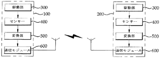
図1は、本発明による動作感覚フィードバックを利用した相互作用装置の構成を概略的に現すブロック図である。
<Configuration of interaction device using motion feedback>
FIG. 1 is a block diagram schematically showing the configuration of an interaction device using motion sense feedback according to the present invention.
(第1の実施例)
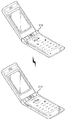
図2は、本発明の第1の実施例による動作感覚フィードバックを利用した相互作用装置の斜視図を示したものである。本発明の第1の実施例は、図2に示すように、相互作用装置100及び相互作用装置200として折り畳み(二つ折り)型携帯用端末機110及び折り畳み(二つ折り)型携帯用端末機210を使用する。説明の便宜のため、以下、ユーザー10(図7に記載)により動作する折り畳み(二つ折り)型携帯用端末機110及び折り畳み(二つ折り)型携帯用端末機210を、便宜上、第1の携帯用端末機110及び第2の携帯用端末機210とする。
(First embodiment)
FIG. 2 is a perspective view of an interaction device using motion sense feedback according to the first embodiment of the present invention. In the first embodiment of the present invention, as shown in FIG. 2, as the
第1の携帯用端末機110及び第2の携帯用端末機210は、図1に示すように、各々内部に駆動部300、センサー400、変換部500、及び通信モジュール600を有する。ここで、駆動部300は、第2の携帯用端末機210を第1の携帯用端末機110と対応するように作動すること、及び第2の携帯用端末機210で発生する動作を第1の携帯用端末機110を通じて、動作感覚フィードバックをユーザー10に伝達するためのものである。このような目的を達成できるものであれば、どのような駆動装置を使用してもかまわない。望ましくは、第1の携帯用端末機110及び第2の携帯用端末機210の折り畳み部分を回転させるためのモーターを使用する構成が良く、より望ましくは、DCモーターを使用するのがよい。また、駆動部300の一側には、駆動部300の動作を制限するブレーキが更に備えられる。このようなブレーキは、第1の携帯用端末機110及び第2の携帯用端末機210が互いに対抗する外部の力710(図7に記載)が加えられる場合、相手の携帯用端末機の動作を制限するものであり、このような目的を達成できるものであれば、どのようなブレーキを使用してもかまわない。しかし、望ましくは、応答時間が早く、安定的な磁粉ブレーキ(Magnetic Particle Brake)を使用するのがよい。このような磁粉ブレーキは、トーク電圧、出力トークなどを容易に調節することができる。
As shown in FIG. 1, the first
本発明の第1の実施例によるセンサー400は、ユーザー10(図7に記載)の操作などのような外部で加えられる力により駆動される駆動部300の動作大きさ、及び動作経路を測定するものであって、第1の携帯用端末機110及び第2の携帯用端末機210の折り畳み部分を作動する駆動部300の動作大きさ、及び動作経路を測定することができるものであれば、どのようなセンサー400を使用してもかまわない。
The
本発明の第1の実施例による変換部500は、センサー400で測定した第1の携帯用端末機110の動作信号を通信のための電気的信号に変換するとか、第2の携帯用端末機210で受信する電気的信号を第2の携帯用端末機210の駆動のための動作信号に変換するためのものである。このような目的を達成できるものであれば、どのような変換部500を使用してもかまわない。しかし、動作信号を携帯用端末機110及び携帯用端末機210の駆動部に取り付けられた変換するエンコーダ、及び受信された電気的信号の雑音を除去し、通信用信号への変換をさせる機能を有する変換部500を使用するのがよい。
The
本発明の第1の実施例による通信モジュール600は、第1の携帯用端末機110及び第2の携帯用端末機210の通信を行うためのものであって、従来の携帯用端末機に含まれるデータモジュール600、及び携帯用端末機制御のための制御用データ通信モジュール600を含む。
The
(第2の実施例)
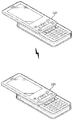
図3は、本発明の第2の実施例による動作感覚フィードバックを利用した相互作用装置の斜視図を示したものである。本発明の第2の実施例による相互作用装置100及び相互作用装置200は、スライド型携帯用端末機120及びスライド型携帯用端末機220を使用する。このような第2の実施例による相互作用装置100及び相互作用装置200の構成は、図1に示すように、第1の実施例と類似した構成からなる。しかし、スライド型携帯用端末機120及びスライド型携帯用端末機220は、折り畳み型携帯用端末機110及び携帯用端末機210の運動とは異なる運動をするから、これに対応する構成からなる。
(Second embodiment)
FIG. 3 is a perspective view of an interaction device using motion sense feedback according to a second embodiment of the present invention. The
第2の実施例による駆動部300は、第1の実施例による駆動部300と同一の目的及び効果のために使用され、スライドの線形動きに好適な線形モーターを使用する。そして、駆動部300の動きを制限するブレーキも線形動きの制限に容易な線形ブレーキ(Linear Brake)を使用する。線形ブレーキは、直線の動きを制限することが容易であり、性能が優れて安定性が高い。
The driving
第2の実施例による変換部500は、線形動きによるデータ変換のための線形エンコーダ、及び線形デコーダを含む変換部500を使用する。
The
第2の実施例で詳細に言及していないセンサー400、及び通信モジュール600などの構成は、第1の実施例と同一の構成からなる。
The configurations of the
(第3の実施例)
図4は、本発明の第3の実施例による動作感覚フィードバックを利用した相互作用装置の正面図を示したものである。本発明の第3の実施例による相互作用装置100及び相互作用装置200は、図4に示されたように、フレキシブルディスプレイ130及びフレキシブルディスプレイ230を使用する。このような第3の実施例による相互作用装置100及び相互作用装置200の構成は、図1に示したように、第1の実施例と類似した構成からなる。しかしフレキシブルディスプレイ130及びフレキシブルディスプレイ230の動作は、携帯用端末機110、携帯用端末機120、携帯用端末機210及び携帯用端末機220とは全く異なる動作をするから、これに対応する構成からなる。
(Third embodiment)
FIG. 4 is a front view of an interaction device using motion sense feedback according to a third embodiment of the present invention. The
フレキシブルディスプレイ130及びフレキシブルディスプレイ230は、画面が表示されるディスプレイ部の一側に複数のワイヤー又はSMAストリップにより駆動される。
The
第3の実施例による駆動部300は、第1の実施例による駆動部300と同一の目的及び効果のために使用され、フレキシブルディスプレイ130及びフレキシブルディスプレイ230の駆動のために、ワイヤー又はSMAストリップを駆動するDCモーター、又はSMAを使用する。
The driving
第3の実施例によるセンサー400は、フレキシブルディスプレイ130及びフレキシブルディスプレイ230の一側、望ましくは、主な曲げが発生する一側に複数個備えられ、フレキシブルディスプレイ130及びフレキシブルディスプレイ230の曲げ方向、及び大きさなどを測定するものである。このような目的を達成できるものであれば、どのようなセンサー400を使用してもよい。望ましくは、抵抗方式、又は光繊維機能を活用した曲げセンサーを使用するのがよい。
A plurality of
第3の実施例で詳細に言及していない変換部500、及び通信モジュール600などの構成は、第1の実施例又は第2の実施例と同一の構成からなる。
The configurations of the
(変形例)
本発明による動作感覚フィードバックを利用した相互作用装置100及び、相互作用装置200は、前述した第1の実施例乃至第3の実施例による装置以外にも、相互通信により操作可能であるPDP、PMP、ノートPC(ノート型パーソナルコンピュータ)、又は2以上の相互装置を利用する電子製品などにも適用可能である。一例として、ノートPCの場合には、相互連結されたノートPCのヒンジ角を前述した原理を通じて相互制御することができる。同一の原理として、デスクトップPCに連結されたモニターのヒンジを、相互連結されたデスクトップPCに連結されたモニターのヒンジを前述した原理を通じて相互制御するごとができる。
(Modification)
The
<動作感覚フィードバックを利用した相互作用装置の作動方法>
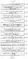
図5は、本発明による動作感覚フィードバックを利用した相互作用装置の作動方法を現す順序図を示したものである。図5に示すように、まず、ユーザー10が第1の相互作用装置100に力を加えて第1の相互作用装置100を操作する(第1ステップ、S100)。
< Operation method of interaction device using motion sense feedback>
FIG. 5 is a flowchart illustrating a method of operating an interaction device using motion sense feedback according to the present invention. As shown in FIG. 5, first, the user 10 applies a force to the
次いで、ユーザー10により操作される第1の相互作用装置100の駆動による動作の大きさ、及び経路などの動作情報を第1の相互作用装置100に備えられたセンサー400で測定する(第2ステップ、S200)。センサー400は、第1の相互作用装置100の種類によって様々な動きが発生することができるから、これに好適な力センサー、トークセンサー、モーションセンサー、加速度測定センサー、又は速度センサーなどのセンサー400を使用する。
Next, the magnitude of the operation by driving the
次に、センサー400で測定した第1の相互作用装置100の作動信号を通信のための電気的信号に変換する(第3ステップ、S300)。
Next, the operation signal of the
次に、電気的信号に変換された第1の相互作用装置100の動作情報を送信し、第2の相互作用装置200で電気的信号を受信する(第4ステップ、S400)。
Next, the operation information of the
次に、第2の相互作用装置200で受信した電気的信号を、第2の相互作用装置200を駆動することのできる動作信号に変換する(第5ステップ、S500)。
Next, the electrical signal received by the
次に、第2の相互作用装置200は、受信した第1の相互作用装置100の動作信号と同一の動作大きさ、及び動作経路で制御S600することにより、1次的な相互作用装置100、200の作動を仕上げる(第6ステップ)。
Next, the
第1の相互作用装置100のユーザー10が、持続的に第1の相互作用装置100を操作する場合には、前述した過程S100乃至S600を繰り返し遂行し、第2の相互作用装置200を第1の相互作用装置100と同一の動きを遂行するようにする。第2の相互作用装置200が障害物700に引っかかる(図6に示す)等、外部からの力が発生しないと、第1の相互作用装置100には別途のフィードバックが発生しない。別途のフィードバックが発生しないことにより、ユーザー10は、第2の相互作用装置200が円滑に作動していることを確認することができる。以下に、第2の相互作用装置200が障害物700に引っかかる等、第2の相互作用装置200で外部の力が作用する場合に発生する作動方法S700(第7ステップ)を説明する。
When the user 10 of the
第1の相互作用装置100を操作し、第2の相互作用装置200が第1の相互作用装置100と同一の動きを遂行する過程において、第1の相互作用装置100の動きに対抗する外部の力、又は障害物700(図6に記載)が第2の相互作用装置200に発生する(第7−1ステップ、S710)。
In the process of operating the
次に、第2の相互作用装置200に備えられたセンサー400で、第2の相互作用装置200に発生した外部の力710により決定された動作大きさ、及び経路などの動作情報を測定する(第7−2ステップ、S720)。
Next, the motion information determined by the external force 710 generated in the
次に、外部の力710に対する動作情報を、通信のための電気的信号に変換する(第7−3ステップ、S730)。 Next, the operation information for the external force 710 is converted into an electrical signal for communication (step 7-3, S730).
次に、電気的信号に変換された外部の力710に対する動作情報を第2の相互作用装置200で送信し、第1の相互作用装置100で受信する(第7−4ステップ、S740)。
Next, the operation information for the external force 710 converted into an electrical signal is transmitted by the
次に、受信した電気的信号を第2の相互作用装置200で発生された外部の力710に対する動作信号に変換する(第7−5ステップ、S750)。このとき、第1の相互作用装置100にユーザー10により発生する動作情報、及び第2の相互作用装置200に発生する外部の力710に対する動作情報を比較する過程を同時に遂行することができる(第7−5´ステップ、S751)。
Next, the received electrical signal is converted into an operation signal for the external force 710 generated by the second interaction device 200 (step 7-5, S750). At this time, the process of comparing the operation information generated by the user 10 in the
最後に、第2の相互作用装置200に発生した外部の力710に対する動作信号に対応する動作感覚フィードバックを、第1の相互作用装置100からユーザー10に提供する(S760)。このとき、発生する動作感覚フィードバックは、従来の触覚フィードバックのように単純な振動などのフィードバックではなく、折り畳み部分の動き、スライドの移動などの動作感覚、又は動作感覚のようなフィードバックを発生する。
Finally, motion sense feedback corresponding to the motion signal for the external force 710 generated in the
<動作感覚フィードバックを利用した相互作用装置の使用様態>
(第1の実施例)
図6は、本発明による動作感覚フィードバックを利用した相互作用装置の器具的動きを表す図を示したものであり、図7は、本発明の第1の実施例による動作感覚フィードバックを利用した相互作用装置の使用様態図を示したものである。図6及び図7aに示したように、ユーザー10が第1の携帯用端末機110の折り畳み部分を閉じると、第2の携帯用端末機210は別途の外部操作がなくても、第1の携帯用端末機110の動きと同一の動作の範囲で折り畳み部分が閉じる。
<Usage of interaction device using motion sensory feedback>
(First embodiment)
FIG. 6 is a diagram showing the instrumental movement of the interaction device using motion sense feedback according to the present invention, and FIG. 7 is a diagram showing mutual motion using motion sense feedback according to the first embodiment of the present invention. FIG. 2 is a diagram showing how the working device is used. As shown in FIGS. 6 and 7a, when the user 10 closes the folded portion of the first
しかし、図6及び図7bに示したように、第2の携帯用端末機210が第1の携帯用端末機110と連動的に操作される過程において、障害物700に引っかかる等、第2の携帯用端末機210に外部の力710が発生すると、第1の携帯用端末機110はこれに相応する動きを起こし、ユーザーにフィードバックを発生させる。このようなフィードバックは、動作感覚、又は動作感覚フィードバックであって、第2の携帯用端末機210に発生する外部の力710がユーザー10の力よりも弱い場合には、第1の携帯用端末機110及び第2の携帯用端末機210の折り畳み部分が少しだけ閉じるとか、遅く閉じるなどのフィードバックを発生する。また、ユーザー10の力と第2の携帯用端末機210の外部の力710とが等しい場合には、第1の携帯用端末機110及び第2の携帯用端末機210の折り畳み部分が震えることにより、第1の携帯用端末機110及び第2の携帯用端末機210に発生する力に対する動作感覚フィードバックを発生する。また、第2の携帯用端末機210に発生する外部の力710がユーザー10の力よりも強い場合には、閉まっていた折り畳み部分が再度開く動作感覚フィードバックを発生する。このような動作感覚フィードバックを発生することにより、第1の携帯用端末機110及び第2の携帯用端末機210のユーザー10は、相互交感が可能である。
However, as shown in FIGS. 6 and 7b, in the process in which the second
(第2の実施例)
図8は、本発明の第2の実施例による動作感覚フィードバックを利用した相互作用装置の使用様態図を示したものである。図6及び図8aに示されたように、ユーザー10が第1の携帯用端末機120をスライドすると、第2の携帯用端末機220は別途の外部操作がなくても、第1の携帯用端末機120の動きと同一の動作の範囲でスライドする。
(Second embodiment)
FIG. 8 is a diagram showing a usage pattern of the interaction device using motion sense feedback according to the second embodiment of the present invention. As shown in FIGS. 6 and 8a, when the user 10 slides the first
しかし、図8bに示したように、第2の携帯用端末機220が第1の携帯用端末機120と連動的に操作される過程において、障害物700に引っかかる等、第2の携帯用端末機220に外部の力710が発生すると、第1の携帯用端末機120でこれに相応するフィードバックを発生する。このようなフィードバックは、動作感覚、又は動作感覚フィードバックであって、第2の携帯用端末機220に発生する外部の力710がユーザー10の力よりも弱い場合には、第1の携帯用端末機120、及び第2の携帯用端末機220のスライドが遅く動作するなどのフィードバックを発生する。また、ユーザー10の力と第2の携帯用端末機220の外部の力710とが等しい場合には、第1の携帯用端末機120及び第2の携帯用端末機220のスライドが震えることにより、第1の携帯用端末機120及び第2の携帯用端末機220に発生する力に対する動作感覚フィードバックを発生する。また、第2の携帯用端末機220に発生する外部の力710がユーザー10の力よりも強い場合には、スライド動作が逆に移動する動作感覚フィードバックを発生する。このような動作感覚フィードバックを発生することにより、第1の携帯用端末機120及び第2の携帯用端末機220のユーザー10は、相互交感が可能である。
However, as shown in FIG. 8b, in the process in which the second
(第3の実施例)
図9は、本発明の第3の実施例による動作感覚フィードバックを利用した相互作用装置の使用様態図を示した断面図である。図9bに示したように、ユーザー10が第1のフレキシブルディスプレイ130を折り曲げると、第2のフレキシブルディスプレイ230は、別途の外部操作がなくても、第1のフレキシブルディスプレイ130の動きと同一の動作大きさに折り曲げられる。
(Third embodiment)
FIG. 9 is a cross-sectional view illustrating a usage pattern of an interaction device using motion sense feedback according to a third embodiment of the present invention. As shown in FIG. 9b, when the user 10 bends the first
第1のフレキシブルディスプレイ130、及び第2のフレキシブルディスプレイ230は、互いに長さが異なるワイヤーなどの駆動部300を利用して折り曲げられる大きさを調節することができ、互いに長さが異なるワイヤーの終端と近接した一側でフレキシブルディスプレイ130、230の折り程度を測定する。
The first
このような第1のフレキシブルディスプレイ130、及び第2のフレキシブルディスプレイ230も、前述した第1の実施例又は第2の実施例による使用様態と類似した過程で作動する。
The first
以上で説明したように、本発明の属する技術の分野における当業者は、本発明がその技術的思想や、必須的特徴を変更することなく、他の具体的な形態に実施され得るということが理解可能である。従って、上述した実施例などは、全ての面において例示的なものであり、限定的なものではないこととして理解するべきである。本発明の範囲は、詳細な説明よりも後述する特許請求の範囲によって示され、特許請求の範囲の意味及び範囲、そして等価概念から導出される全ての変更、又は変形された形態が、本発明の範囲に含まれるものとして解釈される。 As described above, those skilled in the art to which the present invention pertains can say that the present invention can be implemented in other specific forms without changing the technical idea and essential features thereof. It is understandable. Therefore, it should be understood that the above-described embodiments and the like are illustrative in all aspects and not restrictive. The scope of the present invention is defined by the following claims rather than the detailed description, and all modifications or variations derived from the meaning and scope of the claims and the equivalent concepts are disclosed in the present invention. It is interpreted as being included in the scope of
10 ユーザー
100 第1の相互作用装置
110 第1の折り畳み(二つ折り)型携帯用端末機
120 第1のスライド型携帯用端末機
130 第1のフレキシブルディスプレイ
200 第2の相互作用装置
210 第2の折り畳み(二つ折り)型携帯用端末機
220 第2のスライド型携帯用端末機
230 第2のフレキシブルディスプレイ
300 駆動部
400 センサー
500 変換部
600 通信モジュール
700 障害物
710 外部の力
DESCRIPTION OF SYMBOLS 10
Claims (10)
前記各々の相互作用装置100及び相互作用装置200は、
ユーザー10の操作に応じて駆動され、前記相互作用装置100及び前記相互作用装置200を作動させ、ユーザー10に動作感覚フィードバックを提供する駆動部300と、
前記駆動部300の動作の大きさ及び動作経路に該当する動作信号を測定するセンサー400と、
前記センサー400で測定した駆動部300の動作信号を送受信するため、前記動作信号を電気的信号に変換する変換部500と、
前記電気的信号を送受信する通信モジュール600と、を含み、
前記変換部500は、前記センサー400で測定された動作情報を電気的信号に変換するエンコーディング部と、前記通信モジュール600で受信された電気的信号を動作信号に変換するデコーディング部と、からなり、
前記駆動部300は、前記相互作用装置100及び前記相互作用装置200の動きを制限するブレーキを含むこと
を特徴とする動作感覚フィードバックを利用した相互作用装置。 In the interaction device 100 and the interaction device 200 connected by mutual communication,
Each of the interaction device 100 and the interaction device 200 includes:
A driving unit 300 that is driven in response to an operation of the user 10 to actuate the interaction device 100 and the interaction device 200 and provide motion sense feedback to the user 10 ;
A sensor 400 for measuring an operation signal corresponding to an operation magnitude and an operation path of the driving unit 300;
A converter 500 for converting the operation signal into an electrical signal in order to transmit and receive the operation signal of the driving unit 300 measured by the sensor 400;
A communication module 600 for transmitting and receiving the electrical signal, only including,
The conversion unit 500 includes an encoding unit that converts operation information measured by the sensor 400 into an electrical signal, and a decoding unit that converts the electrical signal received by the communication module 600 into an operation signal. ,
The interaction device using motion sense feedback, wherein the driving unit 300 includes a brake that restricts movement of the interaction device 100 and the interaction device 200 .
を特徴とする請求項1に記載の動作感覚フィードバックを利用した相互作用装置。 The interaction device 100 and the interaction device 200 may be a foldable (folded) portable terminal 110 and a portable terminal 210, a slide-type portable terminal 120 and a portable terminal 220, or a flexible The interaction device using motion sense feedback according to claim 1, wherein the interaction device is a soft display 130 and a flexible display 230.
を特徴とする請求項1に記載の動作感覚フィードバックを利用した相互作用装置。 The driver 300, DC motors, linear motors, or interaction device using the operation sensory feedback according to claim 1, characterized in that the SMA.
前記第1の相互作用装置100にユーザー10が力を加えて駆動部300が駆動される第1ステップと、
前記第1の相互作用装置100に備えられたセンサー400で、前記駆動部の動作の大きさ及び動作経路に該当する動作信号を測定する第2ステップと、
前記第1の相互作用装置100に備えられた変換部500が、前記動作信号を電気的信号に変換する第3ステップと、
前記第1の相互作用装置100に備えられた通信モジュール600が、前記電気的信号を前記第2の相互作用装置200に備えられた通信モジュール600に送信する第4ステップと、
前記第2の相互作用装置200に備えられた変換部が、前記電気的信号を動作信号に変換する第5ステップと、
前記第2の相互作用装置200の駆動部300が、前記動作信号と同一の大きさ、及び動作経路で駆動され、ユーザー10に動作感覚フィードバックを提供する第6ステップと、
前記第2の相互作用装置200が障害物700に衝突するか、前記第2の相互作用装置200に外部の力710が加えられると、前記外部の力710に対する動作感覚フィードバックを前記第1の相互作用装置100に伝達する第7ステップとを含み、
前記駆動部300は、前記第1の相互作用装置100及び前記第2の相互作用装置200の動きを制御するブレーキを含むこと
を特徴とする動作感覚フィードバックを利用した相互作用装置の作動方法。 In a method of operating a first interaction device 100 and a second interaction device 200 coupled in communication,
A first step in which the driving unit 300 is driven by the user 10 applying a force to the first interaction device 100;
A second step of measuring an operation signal corresponding to an operation magnitude and an operation path of the driving unit with the sensor 400 provided in the first interaction device 100;
A third step in which the converter 500 provided in the first interaction device 100 converts the operation signal into an electrical signal;
A fourth step in which the communication module 600 included in the first interaction device 100 transmits the electrical signal to the communication module 600 included in the second interaction device 200 ;
A conversion unit provided in the second interaction device 200 converts the electrical signal into an operation signal;
A sixth step in which the driving unit 300 of the second interaction device 200 is driven with the same magnitude and movement path as the movement signal to provide movement sense feedback to the user 10 ;
When the second interaction device 200 collides with the obstacle 700 or when an external force 710 is applied to the second interaction device 200, motion sense feedback for the external force 710 is given to the first interaction device. A seventh step of transmitting to the working device 100;
The driving unit 300 includes a brake that controls movements of the first interaction device 100 and the second interaction device 200. The interaction device using motion sense feedback is provided. Actuation method.
を特徴とする請求項6に記載の動作感覚フィードバックを利用した相互作用装置の作動方法。 The operation of the interaction device using motion feedback according to claim 6, wherein at least one of the first step and the sixth step is driven by a DC motor, a linear motor, or an SMA. Method.
前記第1の相互作用装置100の動きと異なる外部の力710を第2の相互作用装置200に提供する第7−1ステップと、
前記第2の相互作用装置200に備えられたセンサー400で外部の力710に対する動作情報を測定する第7−2ステップと、
前記外部の力710に対する動作情報を電気的信号に変換する第7−3ステップと、
前記第2の相互作用装置200で前記電気的信号を送信し、前記第1の相互作用装置100で受信する第7−4ステップと、
前記第1の相互作用装置100で受信した電気的信号を動作信号に変換する第7−5ステップと、
前記動作信号に対応する動作感覚フィードバックを前記ユーザー10に提供する第7−6ステップと、を含むことを特徴とする請求項6に記載の動作感覚フィードバックを利用した相互作用装置の作動方法。 The seventh step includes
Providing a second interaction device 200 with an external force 710 different from the movement of the first interaction device 100;
A step 7-2 of measuring operation information with respect to an external force 710 by a sensor 400 provided in the second interaction device 200;
Step 7-3 for converting operation information for the external force 710 into an electrical signal;
A seventh to fourth step of transmitting the electrical signal in the second interaction device 200 and receiving it in the first interaction device 100;
A seventh to fifth step of converting an electrical signal received by the first interaction device 100 into an operation signal;
Operating method of the interaction device using the operation sensory feedback according to claim 6, characterized in that it comprises a first 7-6 steps, the providing operation sensory feedback corresponding to the operation signal to the user 10.
Applications Claiming Priority (2)
| Application Number | Priority Date | Filing Date | Title |
|---|---|---|---|
| KR10-2009-0012299 | 2009-02-16 | ||
| KR1020090012299A KR101054359B1 (en) | 2009-02-16 | 2009-02-16 | Interaction Device Using Muscle Sensory Feedback and Its Operation Method |
Publications (2)
| Publication Number | Publication Date |
|---|---|
| JP2010193427A JP2010193427A (en) | 2010-09-02 |
| JP5073730B2 true JP5073730B2 (en) | 2012-11-14 |
Family
ID=42184436
Family Applications (1)
| Application Number | Title | Priority Date | Filing Date |
|---|---|---|---|
| JP2009245233A Expired - Fee Related JP5073730B2 (en) | 2009-02-16 | 2009-10-26 | INTERACTIVE DEVICE USING MOVEMENT SENSITIVE FEEDBACK AND METHOD OF OPERATING THE SAME |
Country Status (4)
| Country | Link |
|---|---|
| US (1) | US20100207745A1 (en) |
| EP (1) | EP2219098A1 (en) |
| JP (1) | JP5073730B2 (en) |
| KR (1) | KR101054359B1 (en) |
Families Citing this family (3)
| Publication number | Priority date | Publication date | Assignee | Title |
|---|---|---|---|---|
| US7953462B2 (en) * | 2008-08-04 | 2011-05-31 | Vartanian Harry | Apparatus and method for providing an adaptively responsive flexible display device |
| US8610663B2 (en) | 2012-02-06 | 2013-12-17 | Lg Electronics Inc. | Portable device and method for controlling the same |
| KR101181505B1 (en) * | 2012-02-28 | 2012-09-10 | 한국과학기술원 | Haptic interface having asymmetric reflecting points |
Family Cites Families (16)
| Publication number | Priority date | Publication date | Assignee | Title |
|---|---|---|---|---|
| US5805140A (en) * | 1993-07-16 | 1998-09-08 | Immersion Corporation | High bandwidth force feedback interface using voice coils and flexures |
| US6028593A (en) * | 1995-12-01 | 2000-02-22 | Immersion Corporation | Method and apparatus for providing simulated physical interactions within computer generated environments |
| US6586859B2 (en) * | 2000-04-05 | 2003-07-01 | Sri International | Electroactive polymer animated devices |
| JP3851459B2 (en) * | 1998-03-31 | 2006-11-29 | 日本電信電話株式会社 | Haptic communication terminal device |
| KR100354825B1 (en) * | 2000-07-28 | 2002-09-30 | 임성식 | Mobile Station able to make Touchable Love Expression |
| JP2002232317A (en) * | 2001-02-07 | 2002-08-16 | Nippon Telegr & Teleph Corp <Ntt> | Haptic communication device |
| US7567232B2 (en) * | 2001-03-09 | 2009-07-28 | Immersion Corporation | Method of using tactile feedback to deliver silent status information to a user of an electronic device |
| FR2834570B1 (en) * | 2002-01-09 | 2004-03-26 | France Telecom | METHOD AND SYSTEM FOR DYNAMICALLY CONTROLLING A FEEDBACK ELEMENT |
| JP2003288158A (en) * | 2002-01-28 | 2003-10-10 | Sony Corp | Portable device with tactile feedback function |
| US20040040800A1 (en) * | 2002-07-31 | 2004-03-04 | George Anastas | System and method for providing passive haptic feedback |
| GB0322489D0 (en) * | 2003-09-25 | 2003-10-29 | British Telecomm | Haptics transmission systems |
| JP2006163579A (en) * | 2004-12-03 | 2006-06-22 | Sony Corp | Information processing system, information processing apparatus, and information processing method |
| US8621348B2 (en) * | 2007-05-25 | 2013-12-31 | Immersion Corporation | Customizing haptic effects on an end user device |
| US9317110B2 (en) * | 2007-05-29 | 2016-04-19 | Cfph, Llc | Game with hand motion control |
| US8265308B2 (en) * | 2007-12-07 | 2012-09-11 | Motorola Mobility Llc | Apparatus including two housings and a piezoelectric transducer |
| US8004391B2 (en) * | 2008-11-19 | 2011-08-23 | Immersion Corporation | Method and apparatus for generating mood-based haptic feedback |
-
2009
- 2009-02-16 KR KR1020090012299A patent/KR101054359B1/en active Active
- 2009-10-22 US US12/603,870 patent/US20100207745A1/en not_active Abandoned
- 2009-10-23 EP EP09173894A patent/EP2219098A1/en not_active Withdrawn
- 2009-10-26 JP JP2009245233A patent/JP5073730B2/en not_active Expired - Fee Related
Also Published As
| Publication number | Publication date |
|---|---|
| US20100207745A1 (en) | 2010-08-19 |
| EP2219098A1 (en) | 2010-08-18 |
| KR101054359B1 (en) | 2011-08-04 |
| KR20100093211A (en) | 2010-08-25 |
| JP2010193427A (en) | 2010-09-02 |
Similar Documents
| Publication | Publication Date | Title |
|---|---|---|
| CN1938675B (en) | Input device having tactile function, information input method, and electronic device | |
| KR101107127B1 (en) | Mobile terminal | |
| US10203757B2 (en) | Systems and methods for shape input and output for a haptically-enabled deformable surface | |
| US20180093178A1 (en) | Systems and Methods for Performing Haptic Conversion | |
| US9851805B2 (en) | Systems and methods for haptically-enabled holders | |
| CN112291395B (en) | Electronic equipment and control method | |
| CN104123035B (en) | Systems and methods for haptic-enabled deformable surfaces | |
| KR102247663B1 (en) | Method of controlling display and electronic device supporting the same | |
| EP3441866A1 (en) | Systems and methods for multi-pressure interaction on touch-sensitive surfaces | |
| CN101558630B (en) | Method and apparatus for controlling transition behavior of graphical user interface elements based on a dynamic recording | |
| US8704647B2 (en) | Haptic feedback case for electronic equipment | |
| KR20110138715A (en) | Image Manipulation Apparatus and Method | |
| JP5073730B2 (en) | INTERACTIVE DEVICE USING MOVEMENT SENSITIVE FEEDBACK AND METHOD OF OPERATING THE SAME | |
| CN113206905B (en) | Electronic equipment, speaker channel configuration method and device | |
| EP2404435B1 (en) | Electroactive actuator for portable communication devices | |
| JP2015225600A (en) | Information apparatus | |
| CN113286025B (en) | Electronic equipment, audio parameter adjusting method and device | |
| TW201246893A (en) | Mobile terminal | |
| JP2006295779A (en) | Portable information equipment | |
| JP2006065507A (en) | Vibration transmission mechanism, vibration waveform data creation method, input device with tactile function, and electronic device | |
| Xu et al. | Xs: Interactive Scissor Mechanisms as Portable and Customizable Shape-Changing Interfaces | |
| CN115002245A (en) | A rotating module and terminal equipment | |
| CN117980875A (en) | Animation operation method, animation operation program and animation operation system | |
| CN217010911U (en) | Electronic device | |
| WO2013084667A1 (en) | Haptic sensation producing device, information terminal, haptic sensation producing method, and computer-readable recording medium |
Legal Events
| Date | Code | Title | Description |
|---|---|---|---|
| A977 | Report on retrieval |
Free format text: JAPANESE INTERMEDIATE CODE: A971007 Effective date: 20110824 |
|
| A131 | Notification of reasons for refusal |
Free format text: JAPANESE INTERMEDIATE CODE: A131 Effective date: 20110916 |
|
| A601 | Written request for extension of time |
Free format text: JAPANESE INTERMEDIATE CODE: A601 Effective date: 20111207 |
|
| A602 | Written permission of extension of time |
Free format text: JAPANESE INTERMEDIATE CODE: A602 Effective date: 20111212 |
|
| A601 | Written request for extension of time |
Free format text: JAPANESE INTERMEDIATE CODE: A601 Effective date: 20120113 |
|
| A602 | Written permission of extension of time |
Free format text: JAPANESE INTERMEDIATE CODE: A602 Effective date: 20120118 |
|
| A601 | Written request for extension of time |
Free format text: JAPANESE INTERMEDIATE CODE: A601 Effective date: 20120216 |
|
| A602 | Written permission of extension of time |
Free format text: JAPANESE INTERMEDIATE CODE: A602 Effective date: 20120221 |
|
| A521 | Request for written amendment filed |
Free format text: JAPANESE INTERMEDIATE CODE: A523 Effective date: 20120316 |
|
| TRDD | Decision of grant or rejection written | ||
| A01 | Written decision to grant a patent or to grant a registration (utility model) |
Free format text: JAPANESE INTERMEDIATE CODE: A01 Effective date: 20120727 |
|
| A01 | Written decision to grant a patent or to grant a registration (utility model) |
Free format text: JAPANESE INTERMEDIATE CODE: A01 |
|
| A61 | First payment of annual fees (during grant procedure) |
Free format text: JAPANESE INTERMEDIATE CODE: A61 Effective date: 20120822 |
|
| R150 | Certificate of patent or registration of utility model |
Free format text: JAPANESE INTERMEDIATE CODE: R150 |
|
| FPAY | Renewal fee payment (event date is renewal date of database) |
Free format text: PAYMENT UNTIL: 20150831 Year of fee payment: 3 |
|
| R250 | Receipt of annual fees |
Free format text: JAPANESE INTERMEDIATE CODE: R250 |
|
| LAPS | Cancellation because of no payment of annual fees |