JP5073498B2 - Lithium ion secondary battery - Google Patents
Lithium ion secondary battery Download PDFInfo
- Publication number
- JP5073498B2 JP5073498B2 JP2007540478A JP2007540478A JP5073498B2 JP 5073498 B2 JP5073498 B2 JP 5073498B2 JP 2007540478 A JP2007540478 A JP 2007540478A JP 2007540478 A JP2007540478 A JP 2007540478A JP 5073498 B2 JP5073498 B2 JP 5073498B2
- Authority
- JP
- Japan
- Prior art keywords
- lithium ion
- ion secondary
- secondary battery
- compartment
- enclosure
- Prior art date
- Legal status (The legal status is an assumption and is not a legal conclusion. Google has not performed a legal analysis and makes no representation as to the accuracy of the status listed.)
- Active
Links
Images


Classifications
-
- H—ELECTRICITY
- H01—ELECTRIC ELEMENTS
- H01M—PROCESSES OR MEANS, e.g. BATTERIES, FOR THE DIRECT CONVERSION OF CHEMICAL ENERGY INTO ELECTRICAL ENERGY
- H01M10/00—Secondary cells; Manufacture thereof
- H01M10/05—Accumulators with non-aqueous electrolyte
- H01M10/058—Construction or manufacture
- H01M10/0585—Construction or manufacture of accumulators having only flat construction elements, i.e. flat positive electrodes, flat negative electrodes and flat separators
-
- H—ELECTRICITY
- H01—ELECTRIC ELEMENTS
- H01M—PROCESSES OR MEANS, e.g. BATTERIES, FOR THE DIRECT CONVERSION OF CHEMICAL ENERGY INTO ELECTRICAL ENERGY
- H01M50/00—Constructional details or processes of manufacture of the non-active parts of electrochemical cells other than fuel cells, e.g. hybrid cells
- H01M50/20—Mountings; Secondary casings or frames; Racks, modules or packs; Suspension devices; Shock absorbers; Transport or carrying devices; Holders
- H01M50/202—Casings or frames around the primary casing of a single cell or a single battery
-
- H—ELECTRICITY
- H01—ELECTRIC ELEMENTS
- H01M—PROCESSES OR MEANS, e.g. BATTERIES, FOR THE DIRECT CONVERSION OF CHEMICAL ENERGY INTO ELECTRICAL ENERGY
- H01M10/00—Secondary cells; Manufacture thereof
- H01M10/05—Accumulators with non-aqueous electrolyte
- H01M10/052—Li-accumulators
- H01M10/0525—Rocking-chair batteries, i.e. batteries with lithium insertion or intercalation in both electrodes; Lithium-ion batteries
-
- H—ELECTRICITY
- H01—ELECTRIC ELEMENTS
- H01M—PROCESSES OR MEANS, e.g. BATTERIES, FOR THE DIRECT CONVERSION OF CHEMICAL ENERGY INTO ELECTRICAL ENERGY
- H01M10/00—Secondary cells; Manufacture thereof
- H01M10/42—Methods or arrangements for servicing or maintenance of secondary cells or secondary half-cells
- H01M10/425—Structural combination with electronic components, e.g. electronic circuits integrated to the outside of the casing
- H01M10/4257—Smart batteries, e.g. electronic circuits inside the housing of the cells or batteries
-
- H—ELECTRICITY
- H01—ELECTRIC ELEMENTS
- H01M—PROCESSES OR MEANS, e.g. BATTERIES, FOR THE DIRECT CONVERSION OF CHEMICAL ENERGY INTO ELECTRICAL ENERGY
- H01M50/00—Constructional details or processes of manufacture of the non-active parts of electrochemical cells other than fuel cells, e.g. hybrid cells
- H01M50/10—Primary casings, jackets or wrappings of a single cell or a single battery
- H01M50/147—Lids or covers
- H01M50/148—Lids or covers characterised by their shape
- H01M50/15—Lids or covers characterised by their shape for prismatic or rectangular cells
-
- H—ELECTRICITY
- H01—ELECTRIC ELEMENTS
- H01M—PROCESSES OR MEANS, e.g. BATTERIES, FOR THE DIRECT CONVERSION OF CHEMICAL ENERGY INTO ELECTRICAL ENERGY
- H01M50/00—Constructional details or processes of manufacture of the non-active parts of electrochemical cells other than fuel cells, e.g. hybrid cells
- H01M50/10—Primary casings, jackets or wrappings of a single cell or a single battery
- H01M50/147—Lids or covers
- H01M50/155—Lids or covers characterised by the material
- H01M50/16—Organic material
-
- H—ELECTRICITY
- H01—ELECTRIC ELEMENTS
- H01M—PROCESSES OR MEANS, e.g. BATTERIES, FOR THE DIRECT CONVERSION OF CHEMICAL ENERGY INTO ELECTRICAL ENERGY
- H01M50/00—Constructional details or processes of manufacture of the non-active parts of electrochemical cells other than fuel cells, e.g. hybrid cells
- H01M50/10—Primary casings, jackets or wrappings of a single cell or a single battery
- H01M50/183—Sealing members
- H01M50/184—Sealing members characterised by their shape or structure
-
- H—ELECTRICITY
- H01—ELECTRIC ELEMENTS
- H01M—PROCESSES OR MEANS, e.g. BATTERIES, FOR THE DIRECT CONVERSION OF CHEMICAL ENERGY INTO ELECTRICAL ENERGY
- H01M50/00—Constructional details or processes of manufacture of the non-active parts of electrochemical cells other than fuel cells, e.g. hybrid cells
- H01M50/10—Primary casings, jackets or wrappings of a single cell or a single battery
- H01M50/183—Sealing members
- H01M50/186—Sealing members characterised by the disposition of the sealing members
-
- H—ELECTRICITY
- H01—ELECTRIC ELEMENTS
- H01M—PROCESSES OR MEANS, e.g. BATTERIES, FOR THE DIRECT CONVERSION OF CHEMICAL ENERGY INTO ELECTRICAL ENERGY
- H01M50/00—Constructional details or processes of manufacture of the non-active parts of electrochemical cells other than fuel cells, e.g. hybrid cells
- H01M50/10—Primary casings, jackets or wrappings of a single cell or a single battery
- H01M50/183—Sealing members
- H01M50/19—Sealing members characterised by the material
- H01M50/191—Inorganic material
-
- H—ELECTRICITY
- H01—ELECTRIC ELEMENTS
- H01M—PROCESSES OR MEANS, e.g. BATTERIES, FOR THE DIRECT CONVERSION OF CHEMICAL ENERGY INTO ELECTRICAL ENERGY
- H01M50/00—Constructional details or processes of manufacture of the non-active parts of electrochemical cells other than fuel cells, e.g. hybrid cells
- H01M50/20—Mountings; Secondary casings or frames; Racks, modules or packs; Suspension devices; Shock absorbers; Transport or carrying devices; Holders
- H01M50/247—Mountings; Secondary casings or frames; Racks, modules or packs; Suspension devices; Shock absorbers; Transport or carrying devices; Holders specially adapted for portable devices, e.g. mobile phones, computers, hand tools or pacemakers
-
- H—ELECTRICITY
- H01—ELECTRIC ELEMENTS
- H01M—PROCESSES OR MEANS, e.g. BATTERIES, FOR THE DIRECT CONVERSION OF CHEMICAL ENERGY INTO ELECTRICAL ENERGY
- H01M50/00—Constructional details or processes of manufacture of the non-active parts of electrochemical cells other than fuel cells, e.g. hybrid cells
- H01M50/20—Mountings; Secondary casings or frames; Racks, modules or packs; Suspension devices; Shock absorbers; Transport or carrying devices; Holders
- H01M50/284—Mountings; Secondary casings or frames; Racks, modules or packs; Suspension devices; Shock absorbers; Transport or carrying devices; Holders with incorporated circuit boards, e.g. printed circuit boards [PCB]
-
- H—ELECTRICITY
- H01—ELECTRIC ELEMENTS
- H01M—PROCESSES OR MEANS, e.g. BATTERIES, FOR THE DIRECT CONVERSION OF CHEMICAL ENERGY INTO ELECTRICAL ENERGY
- H01M50/00—Constructional details or processes of manufacture of the non-active parts of electrochemical cells other than fuel cells, e.g. hybrid cells
- H01M50/50—Current conducting connections for cells or batteries
- H01M50/543—Terminals
- H01M50/547—Terminals characterised by the disposition of the terminals on the cells
- H01M50/55—Terminals characterised by the disposition of the terminals on the cells on the same side of the cell
-
- H—ELECTRICITY
- H01—ELECTRIC ELEMENTS
- H01M—PROCESSES OR MEANS, e.g. BATTERIES, FOR THE DIRECT CONVERSION OF CHEMICAL ENERGY INTO ELECTRICAL ENERGY
- H01M50/00—Constructional details or processes of manufacture of the non-active parts of electrochemical cells other than fuel cells, e.g. hybrid cells
- H01M50/60—Arrangements or processes for filling or topping-up with liquids; Arrangements or processes for draining liquids from casings
- H01M50/609—Arrangements or processes for filling with liquid, e.g. electrolytes
- H01M50/627—Filling ports
- H01M50/636—Closing or sealing filling ports, e.g. using lids
- H01M50/645—Plugs
-
- H—ELECTRICITY
- H01—ELECTRIC ELEMENTS
- H01M—PROCESSES OR MEANS, e.g. BATTERIES, FOR THE DIRECT CONVERSION OF CHEMICAL ENERGY INTO ELECTRICAL ENERGY
- H01M50/00—Constructional details or processes of manufacture of the non-active parts of electrochemical cells other than fuel cells, e.g. hybrid cells
- H01M50/30—Arrangements for facilitating escape of gases
-
- Y—GENERAL TAGGING OF NEW TECHNOLOGICAL DEVELOPMENTS; GENERAL TAGGING OF CROSS-SECTIONAL TECHNOLOGIES SPANNING OVER SEVERAL SECTIONS OF THE IPC; TECHNICAL SUBJECTS COVERED BY FORMER USPC CROSS-REFERENCE ART COLLECTIONS [XRACs] AND DIGESTS
- Y02—TECHNOLOGIES OR APPLICATIONS FOR MITIGATION OR ADAPTATION AGAINST CLIMATE CHANGE
- Y02E—REDUCTION OF GREENHOUSE GAS [GHG] EMISSIONS, RELATED TO ENERGY GENERATION, TRANSMISSION OR DISTRIBUTION
- Y02E60/00—Enabling technologies; Technologies with a potential or indirect contribution to GHG emissions mitigation
- Y02E60/10—Energy storage using batteries
-
- Y—GENERAL TAGGING OF NEW TECHNOLOGICAL DEVELOPMENTS; GENERAL TAGGING OF CROSS-SECTIONAL TECHNOLOGIES SPANNING OVER SEVERAL SECTIONS OF THE IPC; TECHNICAL SUBJECTS COVERED BY FORMER USPC CROSS-REFERENCE ART COLLECTIONS [XRACs] AND DIGESTS
- Y02—TECHNOLOGIES OR APPLICATIONS FOR MITIGATION OR ADAPTATION AGAINST CLIMATE CHANGE
- Y02P—CLIMATE CHANGE MITIGATION TECHNOLOGIES IN THE PRODUCTION OR PROCESSING OF GOODS
- Y02P70/00—Climate change mitigation technologies in the production process for final industrial or consumer products
- Y02P70/50—Manufacturing or production processes characterised by the final manufactured product
Abstract
Description
[発明の分野]
本発明は、リチウムイオン二次電池に関する。特に、本発明は、リチウムイオン二次電池用のエンクロージャに関する。
[Field of the Invention]
The present invention relates to a lithium ion secondary battery. In particular, the present invention relates to an enclosure for a lithium ion secondary battery.
[相互参照]
本願は、中国出願番号第200420095558.4号の、「Lithium Ion Secondary Batteries」と題する中国特許出願(2004年11月18日出願)による優先権を主張する。この出願は参照により本明細書に援用される。
[Cross-reference]
The present application claims priority from a Chinese patent application entitled “Lithium Ion Secondary Batteries” (filed on November 18, 2004), Chinese Application No. 200420095558.4. This application is incorporated herein by reference.
[背景]
リチウムイオン二次電池は1990年代の成功的発展以来、比エネルギーが大きく、動作電圧が高く、自己放電率が低く、サイクル寿命が長く、且つ非汚染性であるため、次第にニッケルカドミウム電池及びニッケル水素電池等、従来のアルカリ二次電池の代わりとなってきている。リチウムイオン二次電池は、携帯電話、ノート型コンピュータ、ポータブルコンピュータ、携帯情報端末(PDA)、ビデオカメラ、デジタルカメラ、ポータブルDVD/VCDプレーヤ及びポータブルMP3プレーヤ等、最近のモバイル電子通信機器において広く使用されている。
[background]
Since lithium ion secondary batteries have had high specific energy, high operating voltage, low self-discharge rate, long cycle life and non-polluting since the successful development in the 1990s, nickel cadmium batteries and nickel hydrogen It has become a substitute for conventional alkaline secondary batteries such as batteries. Lithium ion secondary batteries are widely used in modern mobile electronic communication devices such as mobile phones, notebook computers, portable computers, personal digital assistants (PDAs), video cameras, digital cameras, portable DVD / VCD players and portable MP3 players. Has been.
現在、市販のリチウムイオン電池パックは、電極コア及び電解液を保持する金属シェル及びカバー、並びに保護回路及びプラスチック外殻等の他の装備品から成っている。このようなタイプの電池パックにはいくつかの不都合点がある。 Currently, commercially available lithium ion battery packs consist of metal shells and covers that hold the electrode core and electrolyte, and other equipment such as protective circuits and plastic shells. This type of battery pack has several disadvantages.
第一に、金属シェルとその内容物との組み立てが複雑である。金属シェルの形成には、複数の切り込みに加え、縁部切り落とし、濯ぎ、及び熱乾燥が必要とされる。カバーを形成するにはスタンピング及び部分射出成形が必要となる。さらに、電極柱とカバーとの組み立てにも、複数のプロセスが必要となる。組み立ての複雑性の増大とともに、金属シェル及びカバーの製造の複雑性は、障害(complications)、製造サイクルの延長、及び高い製造コストを生じさせる。 First, the assembly of the metal shell and its contents is complicated. Formation of the metal shell requires edge cutting, rinsing, and heat drying in addition to multiple cuts. Stamping and partial injection molding are required to form the cover. Further, a plurality of processes are required for assembling the electrode pillar and the cover. With increasing assembly complexity, the complexity of manufacturing metal shells and covers results in complications, extended manufacturing cycles, and high manufacturing costs.
電極コアと導電性金属シェル及びカバーとの間に短絡が生じ易い可能性があり、その結果、安全性の問題が生じる。これを解消するにはいくつかの形式の保護方法が採用される必要があり、このこともまた、電池の複雑性及び製造コストを増大させる。 Short circuits can easily occur between the electrode core and the conductive metal shell and cover, resulting in safety issues. To overcome this, several types of protection methods need to be employed, which also increases battery complexity and manufacturing costs.
第三に、金属シェル及びカバー板(それらの内容物ともども)、及び補助的な保護設備は全て、電池パッケージの内側に配置される必要がある。このため、重量及び体積が著しく増大し、電池の重量エネルギー密度及び体積エネルギー密度が減少する。今日の、高容量、軽量、且つ低コストの電池の必要性に伴い、この課題の早急な解決策が必要とされている。 Third, the metal shell and cover plate (along with their contents) and auxiliary protective equipment must all be placed inside the battery package. For this reason, the weight and volume increase significantly, and the weight energy density and volume energy density of the battery decrease. With today's need for high capacity, light weight and low cost batteries, an immediate solution to this challenge is needed.
第四に、このような電池構成の内側には複数の相互溶接スポットがある。これらの溶接スポットは、負極タブと接続板との間、接続板とカバー板との間、正極とカバーとの間等の接点に生じる。これらは、内部抵抗、発熱、及び潜在的な問題が浮上する可能性を増大しかねない。 Fourth, there are a plurality of mutual welding spots inside such a battery configuration. These welding spots are generated at contacts such as between the negative electrode tab and the connection plate, between the connection plate and the cover plate, and between the positive electrode and the cover. These can increase internal resistance, heat generation, and the potential for potential problems to emerge.
したがって、従来技術には限界があるため、軽量であり、高エネルギー密度を有し、製造が簡単であり、コストの低い、新規のリチウムイオン二次電池が望ましい。 Therefore, since there are limitations in the prior art, a new lithium ion secondary battery that is lightweight, has a high energy density, is easy to manufacture, and is low in cost is desirable.
[発明の概要]
本発明の一目的は、高エネルギー密度を有する軽量なリチウムイオン二次電池を提供することである。
[Summary of Invention]
An object of the present invention is to provide a lightweight lithium ion secondary battery having a high energy density.
本発明の他の目的は、構造が単純で製造が容易であるとともに安価であるリチウムイオン二次電池を提供することである。 Another object of the present invention is to provide a lithium ion secondary battery that is simple in structure, easy to manufacture and inexpensive.
本発明は、電極コアを保持する電極コア区画及び保護回路を保持する別個の保護回路区画を有するエンクロージャと、電極コアと、保護回路と、電解液と、電極コア内の電極を保護回路内の回路と接続する端子リードとを有する、リチウムイオン二次電池に関する。エンクロージャは、プラスチック等の非導電性材料から作製される。本発明の利点は、本発明の実施形態であるリチウムイオン電池が単純な構造を有し、製造が容易であるとともに安価であるという点である。 The present invention provides an enclosure having an electrode core section for holding an electrode core and a separate protection circuit section for holding a protection circuit, an electrode core, a protection circuit, an electrolyte, and an electrode in the electrode core in the protection circuit. The present invention relates to a lithium ion secondary battery having a terminal lead connected to a circuit. The enclosure is made from a non-conductive material such as plastic. The advantage of the present invention is that the lithium ion battery which is an embodiment of the present invention has a simple structure, is easy to manufacture and is inexpensive.
本発明の他の利点は、本発明の実施形態であるリチウムイオン電池が、軽量であるとともに高エネルギー密度を有するという点である。 Another advantage of the present invention is that the lithium ion battery that is an embodiment of the present invention is lightweight and has a high energy density.
本発明の上記及び他の目的、態様、及び利点は、添付の図面とともに説明されれば本発明の好適な実施形態の以下の詳細な説明からより良好に理解されるであろう。 The above and other objects, aspects and advantages of the present invention will be better understood from the following detailed description of preferred embodiments of the invention when described in conjunction with the accompanying drawings.
[発明の詳細な説明]
本発明のリチウムイオン二次電池の現時点で好適な実施形態は、保護回路を保持する区画(第1の区画すなわち保護回路コア区画)、電極コアを保持するもう一方の別個の区画(第2の区画すなわち電極コア区画)、及び電解液を有する、エンクロージャを備える。エンクロージャは、1つ又は複数のエンクロージャカバーを有し得る。これらのカバーは、エンクロージャ及び区画を覆い、好ましくは、これらの区画を密閉する。
Detailed Description of the Invention
The presently preferred embodiment of the lithium ion secondary battery of the present invention comprises a compartment holding the protection circuit (first compartment or protection circuit core compartment), and another separate compartment holding the electrode core (second A compartment or electrode core compartment), and an enclosure with electrolyte. The enclosure may have one or more enclosure covers. These covers cover the enclosure and compartments and preferably seal these compartments.
好適な実施形態では、エンクロージャは、1つが電極区画を覆い(第2のカバー)、もう1つが保護回路区画を覆う(第1のカバー)、2つのカバーを有する。エンクロージャの材料(第1の非導電性材料)、一般的にエンクロージャカバー(複数可)の材料(第2の非導電性材料)、第1のカバーの材料(第3の非導電性材料)、及び第2のカバーの材料(第4の非導電性材料)は全て、プラスチック等の非導電性である材料から作製されることができる。第1の非導電性材料、第2の非導電性材料、第3の非導電性材料、及び第4の非導電性材料は、ポリエチレン、ポリプロピレン、ポリエーテルイミド、パーフルオロアルコキシアルカン、ポリアミド、及びポリカーボネートから選択される1つ又は複数の材料とすることができる。 In a preferred embodiment, the enclosure has two covers, one covering the electrode compartment (second cover) and the other covering the protective circuit compartment (first cover). Enclosure material (first non-conductive material), generally enclosure cover (s) material (second non-conductive material), first cover material (third non-conductive material), And the material of the second cover (fourth non-conductive material) can all be made from a non-conductive material such as plastic. The first non- conductive material, the second non- conductive material, the third non- conductive material, and the fourth non- conductive material are polyethylene , polypropylene, polyetherimide, perfluoroalkoxyalkane, polyamide, and It can be one or more materials selected from polycarbonate.
好適な実施形態では、エンクロージャカバー及びエンクロージャは、溝と突起による方式によって嵌合するとともに密閉される。すなわち、エンクロージャは、溝又は突起を有し、エンクロージャカバーは、エンクロージャがエンクロージャカバーによって覆われる際に突起(単数又は複数)が上記溝(単数又は複数)に挿入されるように、対応する突起又は溝を有する。電極コア区画及び保護回路区画が別個の第2のカバー及び第1のカバーを有する実施形態では、好ましくは、第2のカバー及び電極コア区画が溝と突起による方式によって嵌合するとともに密閉される。最適には、第1のカバー及び保護回路区画もまた、溝と突起による方式によって嵌合されるとともに密閉される。好適な実施形態では、電極コア区画はカバーと一緒に、完全に密閉される。完全な密閉を達成するための1つの方法は、溶接を用いることである。好適な溶接方法は、超音波溶接及び高周波溶接を含む。第1の区画及びそのカバーは、多くの異なる手段によって結合することができる。接続手段の例としては、機械的接続、溶接、又は接着がある。好適な方法は超音波溶接、高周波溶接、又は接着剤の使用である。 In a preferred embodiment, the enclosure cover and enclosure are fitted and sealed in a groove and protrusion manner. That is, the enclosure has a groove or protrusion, and the enclosure cover has a corresponding protrusion or protrusion such that the protrusion (s) are inserted into the groove (s) when the enclosure is covered by the enclosure cover. Has a groove. In embodiments where the electrode core section and the protection circuit section have separate second and first covers, the second cover and electrode core section are preferably fitted and sealed in a groove and protrusion manner. . Optimally, the first cover and the protective circuit compartment are also fitted and sealed in a groove and protrusion manner. In a preferred embodiment, the electrode core compartment is completely sealed together with the cover. One way to achieve a complete seal is to use welding. Suitable welding methods include ultrasonic welding and high frequency welding. The first compartment and its cover can be joined by many different means. Examples of connecting means are mechanical connection, welding or gluing. The preferred method is ultrasonic welding, high frequency welding or the use of an adhesive.
安全機能等の追加機能をエンクロージャに付与することができる。例えば、射出成形等の方法によりエンクロージャを形成している間、カバー又は1つ以上の区画に圧力逃し弁を形成することができる。 Additional functions such as safety functions can be added to the enclosure. For example, a pressure relief valve can be formed in the cover or one or more compartments while the enclosure is formed by methods such as injection molding.
いくつかの実施形態では、保護回路は、過充電又は過放電を防止するためにリチウムイオン二次電池において一般的に使用される保護回路板を含むことができる。保護回路はまた、過熱又は大電流を防止するために、回路を遮断又は切り換える部品を含むこともできる。保護回路は、正極及び負極の接点タブに接続される。 In some embodiments, the protection circuit can include a protection circuit board commonly used in lithium ion secondary batteries to prevent overcharge or overdischarge. The protection circuit can also include components that interrupt or switch the circuit to prevent overheating or high current. The protection circuit is connected to the positive and negative contact tabs.
多くのタイプの電極コアを用いることができる。一実施形態では、正極板、仕切り膜、及び負極板を連続層になるように巻回及びスタックすることによって作製された電極コアを用いる。一実施形態では、正極板及び負極板は、それぞれ誘導電流を生成することできる正極タブ及び負極タブに接続される。電極コアは、保護回路に電気的に接続される。次いで、電極コアの正極タブ及び負極タブは、正極及び負極のために端子リードによって保護回路の正極板及び負極板に電気的に接続される。 Many types of electrode cores can be used. In one embodiment, an electrode core produced by winding and stacking a positive electrode plate, a partition film, and a negative electrode plate into a continuous layer is used. In one embodiment, the positive electrode plate and the negative electrode plate are connected to a positive electrode tab and a negative electrode tab that can generate an induced current, respectively. The electrode core is electrically connected to the protection circuit. Then, the positive electrode tab and the negative electrode tab of the electrode core are electrically connected to the positive electrode plate and the negative electrode plate of the protection circuit by terminal leads for the positive electrode and the negative electrode.
上記第2の区画との正極及び負極の上記端子リードの接点は、ホットメルトによって密閉される。さらに、この接点は、用いられる電解液中で密閉ゲルが安定したままであることができる限り、当該密閉ゲルによっても覆うことができる。 The contact of the positive and negative terminal leads with the second compartment is sealed by hot melt. Furthermore, this contact can also be covered by the sealing gel as long as the sealing gel can remain stable in the electrolyte used.
電解液を注入するための注入孔(注入口)は、電極コア区画又は区画用のカバーに配置することができる。注入孔の密閉には、金属エンクロージャに慣行的に用いられるのと同じ密閉機構を使用することができる。例えば、注入口用シーラーを使用することができる。この注入シーラーは金属リベット、金属ビーズ、又はプラスチックリベット等の非導電性リベットとすることができる。上記非導電性リベットの材料は、ポリエチレン、ポリプロピレン、ポリエーテルイミド、パーフルオロアルコキシアルカン、ポリアミド、及びポリカーボネートから成る非導電性材料の群から1つ又は複数とすることができる。 The injection hole (injection port) for injecting the electrolytic solution can be arranged in the electrode core section or the cover for the section. The same sealing mechanism that is conventionally used for metal enclosures can be used to seal the injection hole. For example, an inlet sealer can be used. This injection sealer can be a non-conductive rivet such as a metal rivet, metal bead, or plastic rivet. The non-conductive rivet material may be one or more from the group of non-conductive materials consisting of polyethylene , polypropylene, polyetherimide, perfluoroalkoxyalkane, polyamide, and polycarbonate.
非導電性エンクロージャを備えた、本発明のいくつかの実施形態は、金属シェル及びプラスチックシェルの双方を含む従来のエンクロージャに比して多くの利点を提供する。本発明の実施形態は単純な構造を有する。このようなタイプの非導電性エンクロージャは、金属シェル、及び従来の電池の電極コアの保護に必要とされる補助的な機能の代わりとなる。このことは、電池のスペース及び重量を著しく節減し、電池のエネルギー密度を増大させる。さらに、本発明の非導電性エンクロージャを製造する技術が大幅に単純化される。射出成形等の単純な技術を用いて、非導電性エンクロージャを作製することができる。さらに、非導電性であるエンクロージャでは、缶詰化、分離リングの設置、及びレーザ溶接等、金属部品を用いるエンクロージャに必要とされるプロセスがもはや必要とされなくなる。 Some embodiments of the present invention with non-conductive enclosures provide many advantages over conventional enclosures that include both metal and plastic shells. Embodiments of the present invention have a simple structure. This type of non-conductive enclosure replaces the auxiliary functions required to protect the metal shell and the electrode core of conventional batteries. This significantly saves battery space and weight and increases battery energy density. Furthermore, the technique of manufacturing the non-conductive enclosure of the present invention is greatly simplified. Non-conductive enclosures can be made using simple techniques such as injection molding. Furthermore, non-conductive enclosures no longer require the processes required for enclosures using metal parts, such as canning, installation of separation rings, and laser welding.
また、非導電性エンクロージャの使用により、電池の安全性も改善される。圧力逃し安全機能部等の追加機能部を、コストをほとんど又は全く増大せずにエンクロージャのどこへでも容易に追加することができる。 The use of a non-conductive enclosure also improves battery safety. Additional features such as pressure relief safety features can be easily added anywhere in the enclosure with little or no cost increase.
さらに、これらの実施形態はまた、電池に必要とされる溶接スポットの数も減らす。これにより、内部抵抗が下がり、電池の大電流放電性能が改善される。 In addition, these embodiments also reduce the number of welding spots required for the battery. Thereby, internal resistance falls and the large current discharge performance of a battery is improved.
以下、図1〜図5に示す本発明の好適な実施形態の作製方法及び構造をさらに説明する。 Hereinafter, the manufacturing method and structure of a preferred embodiment of the present invention shown in FIGS. 1 to 5 will be further described.
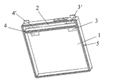
この実施形態では、リチウムイオン電極コア8は、正極板、仕切り膜、及び負極板を連続層になるようにスタックする従来の方法によって作製される。次いで、リチウムイオン電極コアが、正極及び負極のために端子リードを有するエンクロージャの電極コア区画に配置される。次いで、電極コア8の正極タブ12及び負極タブ14が電極コア区画1の正極及び負極の端子リード3、4に、溶接によって接続される。次いで、電極コア区画は、当該電極コア区画の対応する溝10に挿入される突起9を有する、電極コア区画用のプラスチックカバー6で覆われる。電極コア区画はカバーと一緒に超音波溶接によって完全に密閉される。電解液が注入孔又は注入口5を介して注入される。注入後、プラスチックリベットを用いて注入孔5を密閉し、電極コア区画の組み立てが完了する。
In this embodiment, the lithium ion electrode core 8 is manufactured by a conventional method in which a positive electrode plate, a partition film, and a negative electrode plate are stacked to form a continuous layer. A lithium ion electrode core is then placed in the electrode core section of the enclosure having terminal leads for the positive and negative electrodes. Next, the
従来の方法を用いて、保護回路の正極及び負極の接片を、溶接によって保護回路区画2内の正極及び負極の端子リード3’、4’の導電端に接続する。次いで、保護回路区画2を覆い、プラスチックカバー7に溶接して、保護回路区画の組み立てを完了する。このようにして、図1に示すように組み立てられたリチウムイオン二次電池は、充電できる状態となる。
Using conventional methods, the positive and negative contact pieces of the protection circuit are connected to the conductive ends of the positive and negative terminal leads 3 ′, 4 ′ in the
区画間の密閉が確実に維持されるように端子リードを固定するには、いくつかの好適な方法がある。プレハブ式では、端子リードは、非導電性材料の部品によって中央部分が密閉されていることによって作製される。次いで、このプレハブ型端子リードは、2つの区画間のプレカットされたスロットに挿通されて、適所に溶着される。この方法により、端子リードの非導電性中央部分は、区画と同じ材料とすることができ、電池の製造プロセスの際に容易に適所に溶着することができるため、密閉プロセスが単純となる。 There are several suitable ways to secure the terminal leads to ensure that the seal between the compartments is maintained. In the prefabricated type, the terminal lead is made by sealing the central portion with a part of non-conductive material. The prefabricated terminal lead is then inserted into a pre-cut slot between the two compartments and welded in place. This method simplifies the sealing process because the non-conductive central portion of the terminal lead can be the same material as the compartment and can be easily welded in place during the battery manufacturing process.
端子リードを固定するさらに他の好適な方法は、区画間にスロットを直接プレカットすること(直接カット法)である。シーラントを先ずスロットに加え、端子リードをプレカットスロットに挿入し、シーラントを再びスロットに加える。この方法では、プレカットスロットの位置は選択的に設計されてもよい。図示のように、好適な実施形態では、端子リードは平板ストリップであり、この平板ストリップは区画間の平坦なプレカットスロットに配置される。 Yet another preferred method of securing the terminal leads is to directly pre-cut the slots between the compartments (direct cut method). Sealant is first added to the slot, the terminal lead is inserted into the pre-cut slot, and sealant is again added to the slot. In this way, the position of the precut slot may be selectively designed. As shown, in a preferred embodiment, the terminal leads are flat strips that are placed in flat precut slots between the compartments.
好適な実施形態において用いられる端子リードは、導電ストリップ、ワイヤストランド、又はソリッドワイヤとすることができることを理解されたい。代替的な好適な実施形態では、端子リードは、接触面を設けるために両端が平坦にスタンピングされた丸型ソリッドワイヤである。丸型端子リードは、プレハブ式又は直接カット法のいずれかによって適所に配置することができる。丸型ソリッドワイヤを用いる一利点は、振動しやすい環境においてより良好な密閉を維持することができるという点である。 It should be understood that the terminal leads used in the preferred embodiment can be conductive strips, wire strands, or solid wires. In an alternative preferred embodiment, the terminal lead is a round solid wire stamped flat at both ends to provide a contact surface. The round terminal leads can be placed in place by either prefabricated or direct cut methods. One advantage of using a round solid wire is that a better seal can be maintained in an environment prone to vibration.
他の実施形態では、2つの区画を接続する端子リードは、直線状ではない。一実施形態では、端子リードは「s」波状に配置される。さらに他の実施形態では、端子リードは「L」字状に配置される。両者の場合とも、直線状に端子リードを配置するよりも、良好な密閉性を維持することができる。 In other embodiments, the terminal leads connecting the two compartments are not linear. In one embodiment, the terminal leads are arranged in an “s” wave. In yet another embodiment, the terminal leads are arranged in an “L” shape. In both cases, better sealing performance can be maintained than when the terminal leads are arranged linearly.
本発明をいくつかの特定の好ましい実施形態を参照して説明してきたが、本発明がこのようないくつかの特定の実施形態に限定されないことを理解すべきである。むしろ、本発明は、特許請求の範囲に反映される最も広義の意味で理解及び解釈されることが、本発明者等の意図である。したがって、これらの特許請求の範囲は、本明細書に記載されている好ましい実施形態のみならず、当業者にとって明らかな、それらの実施形態の他の及びさらなる代替形態及び変更形態を全て援用していると理解すべきである。 Although the present invention has been described with reference to certain specific preferred embodiments, it should be understood that the invention is not limited to such specific embodiments. Rather, it is the inventors' intention that the present invention be understood and interpreted in the broadest sense as reflected in the claims. Accordingly, these claims incorporate not only the preferred embodiments described herein, but also all other and further alternatives and modifications of those embodiments that will be apparent to those skilled in the art. Should be understood.
1 電極コア区画
2 保護回路区画
3、3’及び4、4’ 正極及び負極の端子リード
5 注入口
6 上記電極コア区画用のカバー
7 上記保護回路区画用のカバー
8 電極コア
9 カバーの突起
10 突起9に対応する溝
12 正極接点タブ
14 負極接点タブ
DESCRIPTION OF
Claims (13)
第1の区画及び第2の区画を有するエンクロージャ、
該エンクロージャ用の1つ又は複数のエンクロージャカバー、
保護回路、及び
電極コアを備え、
前記エンクロージャは第1の非導電性プラスチックから作製され、前記第1の区画は前記保護回路を保持し、前記第2の区画は前記電極コアを保持し、該エンクロージャカバーが第2の非導電性プラスチックから作製されるリチウムイオン二次電池。A lithium ion secondary battery,
An enclosure having a first compartment and a second compartment;
One or more enclosure covers for the enclosure;
A protection circuit and an electrode core,
The enclosure is made from a first non-conductive plastic , the first compartment holds the protection circuit, the second compartment holds the electrode core, and the enclosure cover is a second non-conductive Lithium ion secondary battery made from plastic .
前記第2の区画用の第2のカバーと
をさらに備え、
前記第1のカバーは第3の非導電性プラスチックから作製され、前記第2のカバーは第4の非導電性プラスチックから作製される、請求項1に記載のリチウムイオン二次電池。A first cover for the first compartment;
A second cover for the second compartment,
The lithium ion secondary battery according to claim 1, wherein the first cover is made of a third non-conductive plastic , and the second cover is made of a fourth non-conductive plastic .
前記第2の区画又は前記第2のカバーは注入口を有し、
前記注入口用シーラーは前記注入口を密閉し、
前記注入口用シーラーはリベット又は金属ビーズである、請求項3に記載のリチウムイオン二次電池。Further equipped with an inlet sealer,
The second compartment or the second cover has an inlet;
The inlet sealer seals the inlet,
The lithium ion secondary battery according to claim 3, wherein the inlet sealer is a rivet or a metal bead.
Applications Claiming Priority (3)
| Application Number | Priority Date | Filing Date | Title |
|---|---|---|---|
| CNU2004200955584U CN2772044Y (en) | 2004-11-18 | 2004-11-18 | Lithium ion secondary cell |
| CN200420095558.4 | 2004-11-18 | ||
| PCT/CN2005/001932 WO2006053494A1 (en) | 2004-11-18 | 2005-11-16 | Lithium ion secondary batteries |
Publications (3)
| Publication Number | Publication Date |
|---|---|
| JP2008520067A JP2008520067A (en) | 2008-06-12 |
| JP2008520067A5 JP2008520067A5 (en) | 2011-04-28 |
| JP5073498B2 true JP5073498B2 (en) | 2012-11-14 |
Family
ID=36386734
Family Applications (1)
| Application Number | Title | Priority Date | Filing Date |
|---|---|---|---|
| JP2007540478A Active JP5073498B2 (en) | 2004-11-18 | 2005-11-16 | Lithium ion secondary battery |
Country Status (8)
| Country | Link |
|---|---|
| US (1) | US7851083B2 (en) |
| EP (1) | EP1812979B1 (en) |
| JP (1) | JP5073498B2 (en) |
| KR (1) | KR100864750B1 (en) |
| CN (1) | CN2772044Y (en) |
| AT (1) | ATE437451T1 (en) |
| DE (1) | DE602005015612D1 (en) |
| WO (1) | WO2006053494A1 (en) |
Families Citing this family (24)
| Publication number | Priority date | Publication date | Assignee | Title |
|---|---|---|---|---|
| US8691429B2 (en) * | 2008-10-14 | 2014-04-08 | Samsung Sdi Co., Ltd. | Polymer battery pack and method for manufacturing the same |
| CN102209893B (en) * | 2008-11-28 | 2013-06-26 | 松下电器产业株式会社 | Sensor chip, biosensor system, method for measuring temperature of biological sample, method for measuring temperature of blood sample, and method for measuring concentration of analyte in blood sample |
| EP2211398B1 (en) * | 2009-01-19 | 2018-01-10 | Renata AG | Heavy-duty galvanic element |
| US20100266878A1 (en) * | 2009-04-16 | 2010-10-21 | Ioxus, Inc. | Prismatic polymer case for electrochemical devices |
| KR20110066448A (en) * | 2009-12-11 | 2011-06-17 | 삼성에스디아이 주식회사 | Lithium secondary battery |
| KR101201808B1 (en) * | 2010-06-03 | 2012-11-15 | 삼성에스디아이 주식회사 | Rechargeable battery and method of injecting electrolyte thereinto |
| TWI423500B (en) * | 2010-10-14 | 2014-01-11 | Nat Univ Chin Yi Technology | Lithium ion cell assembly structure integrated by pcb circuits |
| CN102479971B (en) * | 2010-11-30 | 2015-08-26 | 深圳市斯盛能源科技有限公司 | A kind of lithium battery and manufacture method thereof |
| KR101243911B1 (en) * | 2011-03-16 | 2013-03-14 | 삼성에스디아이 주식회사 | Battery pack |
| DE102012206075A1 (en) | 2011-12-15 | 2013-06-20 | Robert Bosch Gmbh | Hard shell cell housing with vapor barrier coating |
| DE102012220386A1 (en) * | 2012-11-08 | 2014-05-08 | Robert Bosch Gmbh | Battery cell with housing cover plate with riveted filler opening |
| US10340483B2 (en) | 2014-08-26 | 2019-07-02 | Cps Technology Holdings Llc | Welding process for sealing a battery module |
| US10388920B2 (en) * | 2014-08-26 | 2019-08-20 | Cps Technology Holdings Llc | Collar for sealing a battery module |
| USD764401S1 (en) * | 2014-09-08 | 2016-08-23 | Parrot Drone | Battery for a remote-controlled toy |
| USD762566S1 (en) * | 2014-09-08 | 2016-08-02 | Parrot Drones | Battery for a headphone |
| CN105885311A (en) * | 2016-06-06 | 2016-08-24 | 苏州锦腾电子科技有限公司 | Impact-resistant flame retardant plastic material and preparing method thereof |
| US11735764B2 (en) | 2018-03-22 | 2023-08-22 | Livent USA Corp. | Printable lithium compositions |
| EP3769358A1 (en) | 2018-03-22 | 2021-01-27 | FMC Lithium USA Corp. | Printable lithium compositions for forming battery electrodes |
| US11264598B2 (en) | 2018-03-22 | 2022-03-01 | Fmc Lithium Usa Corp. | Battery utilizing printable lithium |
| CN109604909B (en) * | 2019-01-25 | 2021-07-02 | 联动天翼新能源有限公司 | Utmost point ear welding position frock |
| AU2019435099A1 (en) | 2019-03-20 | 2021-09-09 | Livent USA Corp. | Printed lithium foil and film |
| CN115769395A (en) | 2020-02-19 | 2023-03-07 | 利文特美国公司 | Fast charging prelithiated silicon negative electrode |
| CN112736340B (en) * | 2020-12-30 | 2023-06-23 | 武汉富航精密工业有限公司 | Injection molding assembly method of secondary battery top cover assembly and top cover assembly |
| US20220255160A1 (en) * | 2021-02-10 | 2022-08-11 | Bell Textron Inc. | Battery Cold Plate and Chassis with Interlocking Joints |
Family Cites Families (15)
| Publication number | Priority date | Publication date | Assignee | Title |
|---|---|---|---|---|
| JPS461852Y1 (en) * | 1967-06-12 | 1971-01-22 | ||
| DE69833604T2 (en) * | 1997-11-05 | 2006-12-21 | Philips Consumer Communications France | Battery unit and portable battery-operated device with such a battery unit |
| KR19990041759A (en) * | 1997-11-24 | 1999-06-15 | 손욱 | Cap Assembly of Secondary Battery |
| JP3899499B2 (en) * | 1998-11-18 | 2007-03-28 | ソニー株式会社 | Non-aqueous electrolyte battery |
| JP3454748B2 (en) * | 1999-02-26 | 2003-10-06 | 三洋電機株式会社 | Battery pack |
| JP3221870B2 (en) * | 2000-01-07 | 2001-10-22 | 松下電器産業株式会社 | Secondary battery with battery protection circuit |
| US6413668B1 (en) * | 2000-01-10 | 2002-07-02 | Delphi Technologies, Inc. | Lithium ion battery and container |
| JP3614767B2 (en) * | 2000-10-20 | 2005-01-26 | 松下電器産業株式会社 | Method for forming exterior body of electrical product |
| JP3653475B2 (en) * | 2001-03-29 | 2005-05-25 | 三洋電機株式会社 | Pack battery |
| JP4154456B2 (en) * | 2001-11-22 | 2008-09-24 | 三洋ジーエスソフトエナジー株式会社 | Battery device with lithium ion battery |
| US7338733B2 (en) * | 2002-04-30 | 2008-03-04 | Sanyo Electric Co., Ltd. | Battery pack |
| CN2593373Y (en) * | 2002-11-22 | 2003-12-17 | 钟玉麟 | Explosion-proof battery |
| JP2004319354A (en) * | 2003-04-18 | 2004-11-11 | Sanyo Gs Soft Energy Co Ltd | Battery pack |
| US7348762B2 (en) * | 2003-05-01 | 2008-03-25 | Sony Corporation | Battery pack and method for producing battery pack |
| US20050271934A1 (en) * | 2004-06-05 | 2005-12-08 | Kiger William B | Battery pack assembly |
-
2004
- 2004-11-18 CN CNU2004200955584U patent/CN2772044Y/en not_active Expired - Lifetime
-
2005
- 2005-11-15 US US11/273,755 patent/US7851083B2/en active Active
- 2005-11-16 JP JP2007540478A patent/JP5073498B2/en active Active
- 2005-11-16 KR KR1020077005703A patent/KR100864750B1/en active IP Right Grant
- 2005-11-16 WO PCT/CN2005/001932 patent/WO2006053494A1/en active Application Filing
- 2005-11-16 DE DE602005015612T patent/DE602005015612D1/en active Active
- 2005-11-16 EP EP05808323A patent/EP1812979B1/en active Active
- 2005-11-16 AT AT05808323T patent/ATE437451T1/en not_active IP Right Cessation
Also Published As
| Publication number | Publication date |
|---|---|
| CN2772044Y (en) | 2006-04-12 |
| KR20070047344A (en) | 2007-05-04 |
| JP2008520067A (en) | 2008-06-12 |
| ATE437451T1 (en) | 2009-08-15 |
| WO2006053494A1 (en) | 2006-05-26 |
| EP1812979A1 (en) | 2007-08-01 |
| US7851083B2 (en) | 2010-12-14 |
| EP1812979B1 (en) | 2009-07-22 |
| KR100864750B1 (en) | 2008-10-22 |
| EP1812979A4 (en) | 2008-03-26 |
| DE602005015612D1 (en) | 2009-09-03 |
| US20060105236A1 (en) | 2006-05-18 |
Similar Documents
| Publication | Publication Date | Title |
|---|---|---|
| JP5073498B2 (en) | Lithium ion secondary battery | |
| KR100342045B1 (en) | Secondary battery | |
| JP4628682B2 (en) | Battery unit and lithium secondary battery using the same | |
| KR100496305B1 (en) | Pouched-type lithium secondary battery and the fabrication method thereof | |
| US8507127B2 (en) | Rechargeable battery | |
| US7541110B2 (en) | Secondary battery | |
| JP4795316B2 (en) | Secondary battery | |
| JP2005203371A (en) | Secondary battery | |
| KR101438439B1 (en) | Battery Cell of Novel Embedded Type Structure | |
| KR101699855B1 (en) | Battery Pack Having Electric Insulating Member | |
| KR101172230B1 (en) | Secondary battery and method for packing the same | |
| KR101381680B1 (en) | Battery Pack Comprising Charging Coil | |
| KR101329830B1 (en) | Secondary battery | |
| KR101422656B1 (en) | Battery Cell of Novel Embedded Type Structure | |
| KR100346378B1 (en) | Lithium polymer battery pack | |
| KR20140099846A (en) | Battery Cell of Novel Embedded Type Structure | |
| CN112259795B (en) | Battery cell assembling method and battery cell | |
| US11522256B2 (en) | Secondary battery | |
| KR100760786B1 (en) | Secondary battery and the same using method | |
| KR100686831B1 (en) | Secondary battery and the same using method | |
| KR101488874B1 (en) | Protection circuit module of improved assemble function | |
| KR102043458B1 (en) | Secondary Battery | |
| KR100647566B1 (en) | Lithium Polymer battery and method for manufacturing the same | |
| KR100922741B1 (en) | Secondary battery | |
| EP4148884A1 (en) | Battery module, battery pack, and vehicle |
Legal Events
| Date | Code | Title | Description |
|---|---|---|---|
| A521 | Request for written amendment filed |
Free format text: JAPANESE INTERMEDIATE CODE: A523 Effective date: 20070515 |
|
| A621 | Written request for application examination |
Free format text: JAPANESE INTERMEDIATE CODE: A621 Effective date: 20070515 |
|
| A977 | Report on retrieval |
Free format text: JAPANESE INTERMEDIATE CODE: A971007 Effective date: 20101020 |
|
| A131 | Notification of reasons for refusal |
Free format text: JAPANESE INTERMEDIATE CODE: A131 Effective date: 20101214 |
|
| A524 | Written submission of copy of amendment under article 19 pct |
Free format text: JAPANESE INTERMEDIATE CODE: A524 Effective date: 20110310 |
|
| A131 | Notification of reasons for refusal |
Free format text: JAPANESE INTERMEDIATE CODE: A131 Effective date: 20120110 |
|
| A521 | Request for written amendment filed |
Free format text: JAPANESE INTERMEDIATE CODE: A523 Effective date: 20120402 |
|
| TRDD | Decision of grant or rejection written | ||
| A01 | Written decision to grant a patent or to grant a registration (utility model) |
Free format text: JAPANESE INTERMEDIATE CODE: A01 Effective date: 20120731 |
|
| A01 | Written decision to grant a patent or to grant a registration (utility model) |
Free format text: JAPANESE INTERMEDIATE CODE: A01 |
|
| A61 | First payment of annual fees (during grant procedure) |
Free format text: JAPANESE INTERMEDIATE CODE: A61 Effective date: 20120822 |
|
| R150 | Certificate of patent or registration of utility model |
Ref document number: 5073498 Country of ref document: JP Free format text: JAPANESE INTERMEDIATE CODE: R150 |
|
| FPAY | Renewal fee payment (event date is renewal date of database) |
Free format text: PAYMENT UNTIL: 20150831 Year of fee payment: 3 |
|
| R250 | Receipt of annual fees |
Free format text: JAPANESE INTERMEDIATE CODE: R250 |
|
| R250 | Receipt of annual fees |
Free format text: JAPANESE INTERMEDIATE CODE: R250 |
|
| R250 | Receipt of annual fees |
Free format text: JAPANESE INTERMEDIATE CODE: R250 |
|
| R250 | Receipt of annual fees |
Free format text: JAPANESE INTERMEDIATE CODE: R250 |
|
| R250 | Receipt of annual fees |
Free format text: JAPANESE INTERMEDIATE CODE: R250 |
|
| R250 | Receipt of annual fees |
Free format text: JAPANESE INTERMEDIATE CODE: R250 |
|
| R250 | Receipt of annual fees |
Free format text: JAPANESE INTERMEDIATE CODE: R250 |
|
| R250 | Receipt of annual fees |
Free format text: JAPANESE INTERMEDIATE CODE: R250 |
|
| R250 | Receipt of annual fees |
Free format text: JAPANESE INTERMEDIATE CODE: R250 |