JP5073478B2 - Horizontal multi-needle quilting machine and method - Google Patents
Horizontal multi-needle quilting machine and method Download PDFInfo
- Publication number
- JP5073478B2 JP5073478B2 JP2007503984A JP2007503984A JP5073478B2 JP 5073478 B2 JP5073478 B2 JP 5073478B2 JP 2007503984 A JP2007503984 A JP 2007503984A JP 2007503984 A JP2007503984 A JP 2007503984A JP 5073478 B2 JP5073478 B2 JP 5073478B2
- Authority
- JP
- Japan
- Prior art keywords
- needle
- looper
- stitch
- pattern
- material web
- Prior art date
- Legal status (The legal status is an assumption and is not a legal conclusion. Google has not performed a legal analysis and makes no representation as to the accuracy of the status listed.)
- Expired - Fee Related
Links
Images


Classifications
-
- D—TEXTILES; PAPER
- D05—SEWING; EMBROIDERING; TUFTING
- D05B—SEWING
- D05B11/00—Machines for sewing quilts or mattresses
-
- D—TEXTILES; PAPER
- D05—SEWING; EMBROIDERING; TUFTING
- D05B—SEWING
- D05B19/00—Programme-controlled sewing machines
- D05B19/02—Sewing machines having electronic memory or microprocessor control unit
- D05B19/12—Sewing machines having electronic memory or microprocessor control unit characterised by control of operation of machine
- D05B19/14—Control of needle movement, e.g. varying amplitude or period of needle movement
-
- D—TEXTILES; PAPER
- D05—SEWING; EMBROIDERING; TUFTING
- D05B—SEWING
- D05B19/00—Programme-controlled sewing machines
- D05B19/02—Sewing machines having electronic memory or microprocessor control unit
- D05B19/12—Sewing machines having electronic memory or microprocessor control unit characterised by control of operation of machine
-
- D—TEXTILES; PAPER
- D05—SEWING; EMBROIDERING; TUFTING
- D05B—SEWING
- D05B65/00—Devices for severing the needle or lower thread
Description
本願は、2005年1月21日出願の米国特許出願第11/040499号明細書の継続であり、それは2004年3月19日出願の米国特許出願第10/804833号明細書の一部継続であり、それは、ここで参照により明示的に本明細書にそれぞれが組み込まれる以下の米国特許仮出願、すなわち、2002年3月6日出願の第60/362179号明細書;2003年2月11日出願の第60/446417号明細書;2003年2月11日出願の第60/446430号明細書;2003年2月11日出願の第60/446419号明細書;2003年2月11日出願の第60/446426号明細書;2003年2月11日出願の第60/446529号明細書;および2003年2月14日出願の第60/447773号明細書(これらのすべてに対する優先権を本願において主張するものであり、かつこれらのすべてが参照によりここで本明細書に組み込まれる)の利益を主張する2003年3月6日出願の国際出願PCT/US第03/07083号明細書の一部継続である。 This application is a continuation of US patent application Ser. No. 11/040499, filed Jan. 21, 2005, which is a continuation of a portion of US Patent Application No. 10/804833, filed Mar. 19, 2004. Yes, which is hereby incorporated by reference herein in its entirety: US Provisional Application No. 60/362179 filed Mar. 6, 2002; Feb. 11, 2003; Application No. 60 / 446,417; Application No. 60 / 446,430 filed on Feb. 11, 2003; No. 60 / 446,419 filed on Feb. 11, 2003; No. 60 / 446,419 filed on Feb. 11, 2003 No. 60/446426; No. 60/446529 filed on Feb. 11, 2003; and No. 60/447773 filed on Feb. 14, 2003. International application PCT / US filed on March 6, 2003, claiming the benefit of (which claims priority to all of these in this application, and all of which are hereby incorporated by reference). This is a partial continuation of the specification of No. 03/07083.
本発明は、キルティングに関し、具体的には高速多針キルティング機械によるキルティングに関する。さらに具体的には、本発明は、例えば、多層材料の幅広いウェブから形成されたマットレスカバーおよび他のキルト製品の製造で使用される種類の多針チェーンステッチキルティング機械に関する。 The present invention relates to quilting, and more particularly to quilting with a high-speed multi-needle quilting machine. More specifically, the present invention relates to multi-needle chain stitch quilting machines of the type used, for example, in the manufacture of mattress covers and other quilt products formed from a wide web of multilayer materials.
キルティングとは、織物材料および他の布地の層を接合して装飾的かつ機能的な圧縮性パネル(panel)を製作する縫製(sewing)処理である。ステッチ型模様(pattern)を使用して縫製設計によってパネルを装飾し、他方でステッチ自体が、キルトを形成する様々な材料層を接合する。マットレスカバーの製造には、大規模なキルティング処理を施すことが伴う。このような大規模なキルティング処理は、多層材料のウェブに沿って一続きのマットレスカバーのパネルを形成するために高速多針キルティング機械を通常使用する。これらの大規模なキルティング処理は、通常、大きな糸巻きによって供給され得るチェーンステッチ縫製ヘッドを使用して、弾性のあるステッチの連鎖を作製する。このような幾つかの機械は、1分間当たり1500以上に及ぶステッチで稼動することが可能であり、幅が約90インチ以上のウェブにわたって型模様を同時にステッチする(stitch)ように、それぞれ1つまたは複数の針列を駆動することができる。より速い速度、より大きな型模様自由度、および高い作業効率が、寝具産業で使用されるキルティング処理の絶えざる目標である。 Quilting is a sewing process in which layers of textile material and other fabrics are joined to produce a decorative and functional compressible panel. The panel is decorated with a sewing design using a stitch pattern, while the stitches themselves join the various layers of material that form the quilt. The manufacture of a mattress cover involves a large-scale quilting process. Such large scale quilting processes typically use a high speed multi-needle quilting machine to form a series of mattress cover panels along a web of multilayer material. These large scale quilting processes typically create a chain of elastic stitches using a chain stitch sewing head that can be supplied by a large spool. Some such machines are capable of running with over 1500 stitches per minute, one each for stitching the pattern simultaneously across a web about 90 inches wide or greater. Alternatively, a plurality of needle rows can be driven. Faster speed, greater pattern freedom, and higher work efficiency are constant goals for quilting processes used in the bedding industry.
従来の多針キルティング機械は、3つの動作軸を有する。材料のウェブがキルティング作業域を通過するとき、X軸をその長手動作方向と考えることができる。このように、材料のウェブが、この材料の上に360度型模様のキルティングが要求される場合などに、いずれの方向でも縫製を容易にするために前進方向または後進方向に移動できる二方向の動きがしばしば与えられる。材料蓄積装置(material accumulator)には、通常二方向機械を取り付け、ウェブ材料の全長の方向をキルティングラインに沿って変更することなく、ウェブの区分を逆向きにできるようにされている。同様にキルト型模様を形成するために、ウェブを横方向に移動させることによって動作のY軸も与えられる。通常、キルティング機構は、キルティング処理においては静止状態に留まり、様々な型模様のキルティングに作用するように材料の動きが制御される。 A conventional multi-needle quilting machine has three motion axes. As the web of material passes through the quilting work area, the X axis can be considered as its longitudinal direction of motion. In this way, the bi-directional web of material can be moved forward or backward to facilitate sewing in either direction, such as when 360 degree pattern quilting is required on the material. Movement is often given. A material accumulator is usually fitted with a two-way machine so that the web sections can be reversed without changing the overall length of the web material along the quilting line. Similarly, the Y axis of motion is also provided by moving the web laterally to form a quilted pattern. Normally, the quilting mechanism remains stationary in the quilting process, and the movement of the material is controlled so as to act on quilting of various patterns.
X軸およびY軸は材料がキルティングされる平面に対して平行であり、従来から水平面である。第3の軸、すなわち、Z軸は材料の平面に対して垂直であり、キルティングステッチを形成する往復動する針の名目上の動作方向を画定する。これらの針は、典型的には材料平面上方の上部縫製ヘッド上に位置し、材料の反対側、すなわち、下側に位置するルーパと協働するが、これらのルーパはZ軸に垂直に、典型的にはX軸方向に往復動する。針駆動部を含む縫製機械の上部は、従来の多針キルティング機械では、大型の静止ブリッジによって担持される。ルーパ駆動部を含む縫製機械の下部は鋳鉄製テーブルに装着される。例えば、それぞれの上部および下部構造にそれぞれ装着された3列の縫製要素が存在し得る。通常、これらの針のすべては単一の主軸に連結され、かつそれによって駆動される。 The X and Y axes are parallel to the plane in which the material is quilted and are conventionally horizontal. The third axis, the Z-axis, is perpendicular to the plane of the material and defines the nominal direction of movement of the reciprocating needle that forms the quilting stitch. These needles are typically located on the upper sewing head above the material plane and cooperate with a looper located on the opposite side of the material, i.e., below, but these loopers are perpendicular to the Z axis, Typically, it reciprocates in the X axis direction. In the conventional multi-needle quilting machine, the upper part of the sewing machine including the needle driving unit is carried by a large stationary bridge. The lower part of the sewing machine including the looper driving unit is mounted on a cast iron table. For example, there may be three rows of sewing elements each attached to each upper and lower structure. Usually, all of these needles are connected to and driven by a single main shaft.
従来の多針キルティング機械は、縫製領域における材料のウェブ区分全体をウェブ幅にわたって圧縮する単一の大型押え金板を使用する。マットレス業界で使用される典型的な機械では、この押え金板は、それぞれの一縫いの間に、サイズが約5,161平方センチメートル(800平方インチ)を越える材料の面積を僅か約0.64cm(1/4インチ)の厚さに圧縮する。それぞれのステッチの形成に続いて針が材料から引き抜かれるとき、押え金板は依然として材料を約1.12cm(7/16インチ)に圧縮しなければならない。材料は、依然として押え金板の下にあるが、型模様を形成するために縫製要素に対して移動しなければならないので、型模様は、材料に対して材料平面に平行に作用する引きずり力によって変形されるのが通常である。これらの従来の機械は大型でかつ重量があり、寝具製造工場の床面のかなりの面積を占有する。 Conventional multi-needle quilting machines use a single large presser plate that compresses the entire web section of material in the sewing area across the web width. In a typical machine used in the mattress industry, this presser plate has an area of material of more than about 5,161 square centimeters (800 square inches) between each stitch and only about 0.64 cm ( Compress to a thickness of 1/4 inch). As the needle is withdrawn from the material following the formation of each stitch, the presser plate still must compress the material to about 7/16 inches. The material is still under the presser plate, but must be moved relative to the sewing element to form the pattern, so that the pattern is driven by a drag force acting on the material parallel to the material plane. Usually it is deformed. These conventional machines are large and heavy and occupy a considerable area on the floor of a bedding factory.
さらには、多針キルティング機械は融通性に欠ける。大半は、同じ型模様および同一の連続ステッチを縫うために同時に動作する1列または多列の固定針を設ける。型模様の変更には、針の物理的な設定、再配置、または着脱、および針の配置変更に関する糸通しが必要である。このような再構成は作業者の時間を奪い、実質的な機械休止時間を要する。 Furthermore, multi-needle quilting machines lack flexibility. Most provide one or multiple rows of fixed needles that operate simultaneously to sew the same pattern and the same continuous stitch. Changing the pattern requires threading for physical setting, repositioning or detachment of the needle, and changing the needle placement. Such reconfiguration takes operator time and requires substantial machine downtime.
キルティングに使用される従来のチェーンステッチ機械は、回転軸によって駆動されるクランク機構を使用して、厚い多層材料を貫通する1つまたは複数の針を往復動させる。駆動モータの力ばかりでなく連結部の慣性も、針を駆動して材料を貫通させる。このように生成された針の動きは従来から正弦的であり、すなわち、それは方程式y=sin xによって表現される曲線によって形成される。このような用途目的では、この方程式を満たさない動きは非正弦的と特徴付けられる。したがって、針の動きは、例えば、材料の上方1インチ持ち上がった位置から、約1/4インチまで圧縮された材料を貫通して下降し、針の動きが逆転する材料下方約1/2インチの点まで針の先端を運ぶ。針は、針糸を材料に通して運び、ルーパ糸によって捕捉される(picked up)材料のルーパ側でループを提供する。材料のルーパ側では、ルーパまたはフックが、軸回りを正弦回転運動で往復動する。このルーパは、その先端が針によって提供された針糸のループに進入し、材料のルーパ側でこの針糸のループにルーパ糸のループを貫通させるように、針に対して位置決めされる。ルーパの動きは、針がそのサイクルの下降区間にあるときに針糸のループがルーパ糸によって捕捉されるように、針の動きに同期化される。次いで、針が持ち上がって材料から引き抜かれ、針糸をルーパおよびルーパ糸のループの回りに延びたままに残す。 Conventional chain stitch machines used for quilting use a crank mechanism driven by a rotating shaft to reciprocate one or more needles through a thick multilayer material. Not only the power of the drive motor but also the inertia of the coupling part drives the needle to penetrate the material. The needle movement thus generated is conventionally sinusoidal, ie it is formed by a curve represented by the equation y = sin x. For such application purposes, movements that do not satisfy this equation are characterized as non-sinusoidal. Thus, the needle movement, for example, from a position raised 1 inch above the material, descends through the compressed material to about 1/4 inch, and about 1/2 inch below the material where the needle movement is reversed. Carry the tip of the needle to the point. The needle carries the needle thread through the material and provides a loop on the looper side of the material picked up by the looper thread. On the looper side of the material, the looper or hook reciprocates around the axis with a sinusoidal motion. The looper is positioned with respect to the needle so that its tip enters a loop of needle thread provided by the needle and causes the loop of thread loop to penetrate the loop of needle thread on the looper side of the material. The looper movement is synchronized to the needle movement so that the loop of the needle thread is captured by the looper thread when the needle is in the descending section of the cycle. The needle is then lifted and withdrawn from the material, leaving the needle thread extending around the looper and loop of the looper thread.
針が材料から引き抜かれるとき、材料はステッチ要素に対して移動され、針が再び下降して、針が貫通した先程の点から1目の長さに等しい距離をおいて材料を貫いて1つのステッチを形成する。針は、再び材料を貫通すると、先程ルーパによって先程の針糸のループに突き通されたルーパ糸に形成されたループに、針糸の次のループを挿通する。このようなサイクルのこの時点では、ルーパ自体は、その正弦往復動で既に針糸のループから引き抜かれており、ルーパ糸のループをステッチ補助要素(数多くの機械でリテーナとして知られ、それは針の次の下降に備えてルーパ糸のループを広げた状態に保つ)の周囲に延びたままに残す。このような過程では、ルーパ糸のループ形成と針糸のループへの通しとを交互に行いながら、針糸のループが形成されかつルーパ糸のループに通され、それによって材料のルーパ側に沿って交互する針糸およびルーパ糸のループの連鎖ができ上がり、材料の針側で見られる針糸のみで形成された一連のステッチを残す。 When the needle is withdrawn from the material, the material is moved relative to the stitching element, and the needle is lowered again, passing one material through the material at a distance equal to the length of the first eye from the point where the needle has penetrated. Form stitches. When the needle penetrates the material again, the next loop of the needle thread is inserted into the loop formed in the looper thread that has been pierced by the looper of the previous needle thread. At this point in such a cycle, the looper itself has already been withdrawn from the needle thread loop with its sinusoidal reciprocation, and the looper thread loop is known as a retainer in many stitch assist elements (which are known as retainers in many machines). Leave the loop of the looper thread open for the next descent). In such a process, the loop of the looper thread and the threading of the needle thread through the loop of the needle thread are alternately formed, and the loop of the needle thread is formed and passed through the loop of the looper thread, thereby along the looper side of the material. A chain of alternating needle and looper yarn loops is created, leaving a series of stitches formed solely of needle threads found on the needle side of the material.
チェーンステッチ形成機械における針およびルーパの従来の正弦的な動きは、長年の経験を通じて、ステッチが縫製過程で欠損しないように糸が確実にループを捕らえ続けるように調整されてきた。高速キルティング機械では、針の動きは、針先端が材料平面の下方または材料を支持する針プレートの下方に、針サイクルの約1/3、すなわち、針サイクルの120度の間存在するようになっている。 Traditional sinusoidal movements of needles and loopers in chain stitch forming machines have been coordinated through years of experience to ensure that the thread continues to catch the loop so that the stitches do not break during the sewing process. In a high speed quilting machine, the needle movement will be present for about 1/3 of the needle cycle, ie 120 degrees of the needle cycle, with the needle tip below the material plane or below the needle plate supporting the material. ing.
針が材料を貫通する針のサイクル部分の間、材料は針に対して移動しないことが好ましい。機械の構成要素および材料の慣性によって、針が材料を貫通することによって、ステッチ動作の間に針に対する材料の僅かな動きが多少引き起こされる。これは針の撓みに繋がり、それによってルーパが針糸のループを捕らえ損なったりまたは針がルーパ糸のループを捕らえ損なったりするのでステッチを欠損させるか、あるいは材料が伸張および変形するので型模様の形成を損なわせる恐れが生じる。さらには、針が布地を貫通する時間を制限すると、針が布地を貫通する速度を形成するが、それによって針が厚い多層材料を貫通する能力が決まる。その場合に、針の速度の上昇には針の移動距離の増大が必要になり、ステッチ形成時に、布地の下方で、ステッチを引き締めるために引き上げなければならない針糸の過剰なたるみを引き起こす。したがって、従来の針の動きは、チェーンステッチ縫製、特に高速キルティングを制約する。 The material preferably does not move relative to the needle during the cycle portion of the needle where the needle penetrates the material. Due to the mechanical components and the inertia of the material, the needle penetrates the material, causing some slight movement of the material relative to the needle during the stitching operation. This leads to needle deflection, which causes the looper to miss the loop of the needle thread, or the needle to fail to catch the loop of the looper thread, causing stitches to be lost or the material to stretch and deform. There is a risk of damaging the formation. Furthermore, limiting the time that the needle penetrates the fabric creates a speed at which the needle penetrates the fabric, which determines the ability of the needle to penetrate the thick multilayer material. In that case, increasing the needle speed requires an increase in the distance traveled by the needle, causing excessive slack in the needle thread that must be pulled up to tighten the stitch below the fabric during stitch formation. Thus, conventional needle movement limits chain stitch sewing, particularly high speed quilting.
さらには、既知の多針キルティング機械のルーパヘッドは、カム従動節をカム表面上に移動させることによってルーパの動きを与えるが、この構造は潤滑が必要であり、保守を必要とする摩耗要素をもたらす。 Furthermore, the looper head of known multi-needle quilting machines provides looper movement by moving the cam follower onto the cam surface, but this structure requires lubrication and provides a wear element that requires maintenance. .
加えて、多針キルティング機械で使用されるチェーンステッチ形成要素は、それぞれ材料の対面側から材料を貫通して往復動する針、および材料の裏側で、貫通する針によって形成された上糸のループを貫通して材料の裏側の経路で揺動するルーパまたはフックを具備するのが通常である。チェーンステッチは、材料の裏側で針とルーパの相互作用によって材料の裏側で上糸と下糸との間の交互連結の縦続列または連鎖を形成するものであり、それは同時に材料の表面側で上糸の完璧な一連のステッチを形成するものである。一連のステッチを確実に形成するには、針およびルーパがどちらも対向する糸のループの捕捉に失敗しないように、それぞれのステッチ要素セットの針およびルーパの経路を正確に確立する必要がある。このようなループを捕らえ損なうと、縫製型模様の欠陥である欠損ステッチをもたらす。 In addition, the chain stitch forming elements used in multi-needle quilting machines each have a needle that reciprocates through the material from the opposite side of the material, and a loop of the upper thread formed by the penetrating needle on the back side of the material It is usual to have a looper or hook that oscillates in the path behind the material. Chain stitches form an interlocking cascade or chain between upper and lower threads on the back side of the material by the interaction of needles and loopers on the back side of the material, which at the same time up on the surface side of the material. It forms a complete series of stitches of yarn. To reliably form a series of stitches, the needle and looper paths of each stitch element set need to be accurately established so that neither the needle nor the looper fails to capture the opposing thread loop. Failure to capture such a loop results in a missing stitch that is a defect in the sewing pattern.
キルティング機械の使用時の最初に、かつ周期的に、針およびルーパの相対位置を調整しなければならない。通常は、この調整にはルーパの位置をその揺動軸上で横方向の調整を行うことが伴う。多針キルティング機械では、このような調整は、ルーパの経路を上糸が通される針の目の直上の針面に密接させるために行われる。この位置では、ルーパ先端が下糸のループを挿通する針糸のループが、針の近傍に形成される。これらのループの形成およびステッチ連鎖の相互連結が、ここで参照により明示的に本明細書に組み込まれる特許文献1に詳細に開示されている。 At the beginning and periodically during use of the quilting machine, the relative position of the needle and looper must be adjusted. Normally, this adjustment involves adjusting the position of the looper laterally on its swing axis. In a multi-needle quilting machine, such adjustment is performed to bring the looper path into close contact with the needle surface directly above the eye of the needle through which the upper thread is passed. At this position, a needle thread loop in which the looper tip is inserted through the lower thread loop is formed in the vicinity of the needle. The formation of these loops and the interconnection of stitch chains is disclosed in detail in US Pat.
ルーパ調整は通常は人手による工程であった。この調整は、針がキルティングされている材料下側の針の移動経路中の最下位点に接近しているときにルーパが針に接近するかまたは軽く当たるように、ルーパを緩め、再位置決めし、点検し、かつ締め付けるための何らかの種類の手道具を使用して、技術者によって機械を停止して行われる。このような調整は作業者の一定の時間量を奪う。多針キルティング機械では、針の数が多く、調整時間が大幅に掛かる恐れがある。針の調整のためにキルティングラインがほとんど1時間かまたはそれ以上も停止することになるのは珍しくない。 Looper adjustment was usually a manual process. This adjustment loosens and repositions the looper so that it approaches or lightly strikes the needle when the needle is approaching the lowest point in the path of travel of the needle below the material being quilted. This is done by stopping the machine by a technician, using some kind of hand tool for checking and tightening. Such adjustment takes a certain amount of time for the operator. In a multi-needle quilting machine, the number of needles is large, and there is a risk that adjustment time will be significantly increased. It is not uncommon for the quilting line to stop for almost an hour or more due to needle adjustment.
さらには、ルーパ調整は人手による工程であったので、調整要素に接近する難しさ、相対的なルーパおよび針の位置を決める難しさ、および調整要素を定位置に保持し、他方で組立体の固締構成要素を固定または固締する難しさが調整誤差の源になってきた。 Furthermore, since the looper adjustment was a manual process, it was difficult to access the adjustment element, the relative looper and needle were difficult to position, and the adjustment element was held in place while the assembly Difficulties in securing or fastening the fastening components have become a source of adjustment error.
多針キルティング機械で使用されるチェーンステッチ形成要素はそれぞれが、材料の対面側から材料を貫通して往復動する針、および材料の裏側の経路で、貫通する針によって材料の裏側で形成された上糸のループを貫通して揺動するルーパまたはフックを具備するのが通常である。チェーンステッチは、材料の裏側で針とルーパの相互作用によって材料の裏側で上糸と下糸との間の交互連結の縦続列または連鎖を形成するものであり、それは同時に材料の表面側で上糸の完璧な一連のステッチを形成する。上糸または針糸は布地を布地の表側すなわち対面側から貫通して、布地の裏側でループを形成する。下糸は、上糸のループと交互連結するループの連鎖を形成する布地の裏側だけに留まる。 Each of the chain stitch forming elements used in a multi-needle quilting machine was formed on the back side of the material by a needle penetrating through the material from the opposite side of the material, and a path through the back side of the material It is usual to have a looper or hook that swings through the loop of the upper thread. Chain stitches form an interlocking cascade or chain between upper and lower threads on the back side of the material by the interaction of needles and loopers on the back side of the material, which at the same time up on the surface side of the material. Form a perfect series of stitches of yarn. The upper thread or the needle thread penetrates the fabric from the front side, that is, the facing side, and forms a loop on the back side of the fabric. The lower thread stays only on the back side of the fabric forming a chain of loops that alternate with the upper thread loop.
高速多針キルティング機械は、マットレスカバーの製造で使用される機械のように、しばしば型模様構成要素の断続的な列で型模様を縫う(sew)。このような縫製(sewing)では、タックステッチが作製され、型模様構成要素のキルティングの最後で、少なくとも上糸が切断される。次いで、布地は針に対して新たな型模様構成要素の始まりに前進するが、そこでより多くのタックステッチが作製されて縫製が再開する。このような1つの高速多針キルティング機械も上記で参照した特許文献1に説明されている。当該特許は、このような多針キルティング機械において糸を切断する1つの方法を特に詳細に説明する。したがって、多針キルティング機械における、より確実でより効率的な糸処理に対する要望が存在する。
High speed multi-needle quilting machines, like machines used in mattress cover manufacture, often sew a pattern with intermittent rows of pattern elements. In such sewing, a tack stitch is produced, and at least the upper thread is cut at the end of the quilting of the pattern component. The fabric then advances to the beginning of a new pattern component relative to the needle, where more tack stitches are made and sewing resumes. One such high-speed multi-needle quilting machine is also described in
高速多針キルティング機械のこれらの特徴および要件、ならびに以上に論じた欠点は、従来のキルティング機械における、より高い速度およびより大きな型模様融通性の実現を阻害する。したがって、特に寝具業界で使用される大量キルティングのために、これらの障害を克服して、キルティング処理の作業効率を増大させる必要性が存在する。
本発明の主要な目的は、特に、寝具産業で見られるような高速で、大規模なキルティング用途におけるキルト製作の効率および経済性を向上させることである。本発明の特定の目的には、キルティング速度の向上、キルティング機器のサイズおよび費用の低減、および従来技術の型模様に優る、作製されたキルト型模様における自由度の向上が含まれる。 The main objective of the present invention is to improve the efficiency and economy of quilt fabrication, especially in the high speed, large scale quilting applications found in the bedding industry. Particular objects of the present invention include increased quilting speed, reduced quilting equipment size and cost, and increased freedom in the produced quilt pattern over prior art pattern patterns.
本発明の他の目的は、多針キルティング機械における針の配置に融通性を与えることである。本発明の追加的な目的は、多針キルティング機械作業における針の設定変更に要する、機械の休止時間および作業者の時間を削減することである。 Another object of the present invention is to provide flexibility in needle placement in a multi-needle quilting machine. An additional object of the present invention is to reduce machine downtime and operator time required to change needle settings in multi-needle quilting machine operations.
本発明の特定の目的は、多針キルティング機械の様々な構成に適合可能であり、様々なサイズ、種類、および配向の幾つもの機械、例えば、単一または多針機械、1つまたは複数の針の列を有する機械、様々に離間された針を有する機械、および垂直、水平、または別様に配向された針を有する機械で使用できるキルティングヘッドを提供することである。本発明の別の目的は、様々な方向で縫うために、様々な型模様を縫うために、または様々な速度で縫うために、同じ機械で様々に動作可能な縫製ヘッドを提供することである。 A particular object of the present invention is adaptable to various configurations of multi-needle quilting machines, and several machines of various sizes, types and orientations, such as single or multi-needle machines, one or more needles It is intended to provide a quilting head that can be used on machines having multiple rows of needles, machines having variously spaced needles, and machines having vertical, horizontal, or otherwise oriented needles. Another object of the present invention is to provide a sewing head that can be operated differently on the same machine, for sewing in various directions, for sewing various patterns, or for sewing at various speeds. .
本発明の別の目的は、キルティング機械における縫製要素の調整の確実性を向上させることである。本発明のさらに特定の目的は、キルティング機械の作業者によって迅速かつ確実に実行可能なルーパ調整を提供することである。本発明の他の目的は、キルティング機械のチェーンステッチ縫製ヘッドのルーパが適切に調整されているとき、または適切に調整されないときを確実に知らせることである。 Another object of the present invention is to improve the certainty of the adjustment of the sewing elements in the quilting machine. A more specific object of the present invention is to provide a looper adjustment that can be performed quickly and reliably by an operator of the quilting machine. Another object of the present invention is to reliably notify when the loop stitcher of the chain stitch sewing head of the quilting machine is properly adjusted or not properly adjusted.
本発明の他の目的は、多針キルティング機械の糸の切断を実現することである。本発明のより具体的な目的は、別々に動作可能であるか、または別々に移動、交換、もしくは再構成が可能であるヘッドを有する多針キルティング機械における糸切りを実現することである。本発明の別の目的は、キルティング機械、特に、多針キルティング機械における糸の張力をより確実に監視及び/又は制御することである。本発明のより具体的な目的は、このようなキルティング機械における糸の張力を自動的に管理および調整することである。 Another object of the present invention is to achieve thread cutting of a multi-needle quilting machine. A more specific object of the present invention is to achieve thread trimming in a multi-needle quilting machine having a head that can be operated separately or can be moved, replaced, or reconfigured separately. Another object of the present invention is to more reliably monitor and / or control yarn tension in quilting machines, particularly multi-needle quilting machines. A more specific object of the present invention is to automatically manage and adjust yarn tension in such quilting machines.
本発明の原理によれば、針が、従来技術の多針キルティング機械によって使用されるような垂直方向以外で往復動する、多針キルティング機械が提供される。本発明のキルティング機械は、従来の多針キルティング機械の動作軸とは異なる幾つかの動作軸を提供する。本発明の例示の実施形態では、針が水平方向に往復動する間、素材は垂直平面内に支持される。針が水平に配向された状態で素材を垂直平面内に支持することが好ましく、かつ重要な利点を有するが、他の非水平の素材配向(すなわち、平面配向に対して実質的な垂直成分を有し、本明細書では一般に垂直と呼ぶ)および非垂直の針配向(すなわち、針配向に対して実質的な水平成分を有し、本明細書では一般に水平と呼ぶ)は、本発明の特徴の多くに適合し、他方で本発明の幾つかの特徴は任意の素材または針配向に関して利点を提供することができる。 In accordance with the principles of the present invention, a multi-needle quilting machine is provided in which the needle reciprocates in a non-vertical direction as used by prior art multi-needle quilting machines. The quilting machine of the present invention provides several operating axes that are different from the operating axes of conventional multi-needle quilting machines. In an exemplary embodiment of the invention, the blank is supported in a vertical plane while the needle reciprocates horizontally. It is preferable to support the material in a vertical plane with the needle oriented horizontally, and has significant advantages, but other non-horizontal material orientation (i.e. a substantial vertical component relative to the planar orientation). And non-vertical needle orientation (ie, having a substantial horizontal component to the needle orientation and generally referred to herein as horizontal) is a feature of the present invention. While some features of the present invention can provide advantages with respect to any material or needle orientation.
本発明の幾つかの原理によれば、キルティング機械の好ましい一実施形態には、別々にまたは個々に制御可能である2つ以上のブリッジを設けられている。それぞれのブリッジには、縫製針の列が設けられ得る。これらの針は、それぞれが別々にもしくは個々に、または様々に組み合わせて一緒に駆動され得る。 In accordance with some principles of the present invention, a preferred embodiment of a quilting machine is provided with two or more bridges that can be controlled separately or individually. Each bridge may be provided with a row of sewing needles. These needles can each be driven separately or individually or in various combinations together.
本発明の例示の実施形態によれば、7つの動作軸が設けられる。これらは一方向のX0−軸を含み、それは1つの下流側方向のみに材料の送出しをもたらす。別の実施形態では、二方向のX−軸動作が備わる。このX−軸動作は、ウェブの形態にある材料をキルティング台を通じて前送りする送出しロールの回転によってもたらされる。 According to an exemplary embodiment of the present invention, seven motion axes are provided. These include a unidirectional X0-axis, which provides material delivery in only one downstream direction. In another embodiment, bi-directional X-axis motion is provided. This X-axis motion is caused by the rotation of a delivery roll that feeds material in the form of a web through a quilting table.
さらに、例示の実施形態によれば、針とルーパの刺繍機構を担持する別々に移動可能なブリッジに2つの動作軸、すなわち、X1、Y1およびX2、Y2がそれぞれに設けられる。Y−軸動作は、それぞれのブリッジを左右に、ウェブに対して平行に、かつその長さおよび動作の方向に対して横方向に移動し、他方では、X−軸動作は、このブリッジをウェブに対して平行に上下に、かつその動作方向に対して平行に移動する。二方向のウェブ動作が与えられる代替的な実施形態では、ブリッジのX−軸動作が必ずしも設けられるとは限らない。ブリッジのX、Y動作は、ブリッジのそれぞれに対して別々に制御されるXおよびY駆動部によってもたらされる。ブリッジのY−軸動作は、約18インチ、すなわち、中心位置のそれぞれの側でそれぞれの方向に9インチの範囲を有し、ブリッジのX−軸動作は、ウェブまたはブリッジがX方向に移動するかしないかにかかわらず、ウェブの動作に対して36インチの範囲を有することが好ましい。 Further, according to an exemplary embodiment, two movable axes, namely X1, Y1 and X2, Y2, are provided on separately movable bridges carrying the needle and looper embroidery mechanisms, respectively. Y-axis motion moves each bridge to the left and right, parallel to the web, and transverse to its length and direction of motion, while X-axis motion moves the bridge across the web It moves up and down parallel to the movement direction and parallel to the operation direction. In alternative embodiments where bi-directional web motion is provided, the X-axis motion of the bridge is not necessarily provided. The X, Y motion of the bridge is provided by X and Y drives that are controlled separately for each of the bridges. The Y-axis movement of the bridge has a range of about 18 inches, ie 9 inches in each direction on each side of the center position, and the X-axis movement of the bridge moves the web or bridge in the X direction. Regardless, it is preferred to have a range of 36 inches for web operation.
本発明の幾つかの原理によれば、キルティング機械に、水平または垂直配向にある針と一緒に動作可能な1つまたは複数のキルティングヘッドが設けられる。本発明の他の態様によれば、自己内蔵式縫製ヘッドが設けられ、それは同じかまたは異なる型模様を、同じかまたは異なる方向に、あるいは、同じかまたは異なる速度もしくはステッチ率で縫うために、同じ動作で同期してまたは別々に、単独でまたは1以上の他のこのような縫製ヘッドと組み合わせて動作可能である。 In accordance with some principles of the present invention, a quilting machine is provided with one or more quilting heads operable with needles in a horizontal or vertical orientation. According to another aspect of the present invention, a self-contained sewing head is provided, which sews the same or different pattern, in the same or different directions, or at the same or different speeds or stitch rates. It can be operated synchronously or separately in the same operation, alone or in combination with one or more other such sewing heads.
本発明の幾つかの原理によるキルティング機械の好ましい一実施形態が、静止台枠または可動ブリッジの上で連動可能であり、さらに、1以上の他の縫製ヘッドと組み合わせて、または個々にもしくは別々に制御されて動作するように、別の台枠またはブリッジ上の個々別々のグループとして連動される1以上の他のヘッドと共に、そのように配置可能である縫製ヘッドを設ける。 One preferred embodiment of a quilting machine according to some principles of the present invention can be interlocked on a stationary underframe or movable bridge, and in combination with one or more other sewing heads, or individually or separately. In order to operate in a controlled manner, a sewing head is provided that is so disposable with one or more other heads that are interlocked as separate groups on another frame or bridge.
本発明の例示の実施形態では、ブリッジは個々別々に支持および移動され、さらにそれぞれのブリッジ上に幾つかの個々別々に動作可能な縫製ヘッドが支持される。これらのブリッジのそれぞれが、個々別々に、キルティングされている材料の平面に対して横方向および長手方向の両方に、制御されかつ移動され得る。これらのブリッジは、キルティングすべき材料の垂直に延びる経路の周囲で離隔される共通の脚支持体に取り付けられ、ブリッジは、それぞれの脚支持体に組み込まれた共通の線形軸受け滑動システムによって案内される。それぞれの脚はまた、複数の釣合重りを、それぞれのブリッジに1つ担持する。それぞれのブリッジは、異なる個々に制御可能なサーボモータによって垂直にかつ水平横方向に個々に駆動される。それぞれのブリッジのモータは、ブリッジの垂直および水平移動をもたらす。 In an exemplary embodiment of the invention, the bridges are individually supported and moved, and several individually operable sewing heads are supported on each bridge. Each of these bridges can be controlled and moved individually, both laterally and longitudinally relative to the plane of the material being quilted. These bridges are attached to a common leg support that is spaced around a vertically extending path of material to be quilted, and the bridges are guided by a common linear bearing sliding system incorporated in each leg support. The Each leg also carries a plurality of counterweights, one on each bridge. Each bridge is individually driven vertically and horizontally laterally by different individually controllable servo motors. Each bridge motor provides vertical and horizontal movement of the bridge.
さらには、本発明の幾つかの態様によれば、それぞれのブリッジは、縫製要素、針、およびルーパを往復動するために個々に制御可能な駆動部を有する。この駆動部は、最も実用的には、これら要素の往復動リンク機構を動作させる、回転軸からのような回転入力である。ブリッジのそれぞれの駆動部の個々の動作は、縫製ヘッドまたは縫製ヘッドのグループの個々の縫製動作が可能とし、または1以上の他のヘッドが縫製している間、1以上のヘッドを遊ばせることが可能である。これらのヘッドはそれぞれが、制御装置からの制御に応答し、好ましくは、コモンバス上ですべてのヘッドに送信されたデジタル信号に応答する要素を有し、それぞれの制御可能な要素にはそれぞれの要素に振り向けられるバスからの信号を選択する復号回路が設けられる。 Further in accordance with some aspects of the present invention, each bridge has an individually controllable drive for reciprocating sewing elements, needles and loopers. This drive is most practically a rotational input, such as from a rotating shaft, that operates the reciprocating link mechanism of these elements. Individual movement of each drive of the bridge allows individual sewing movements of the sewing head or group of sewing heads or allows one or more heads to play while one or more other heads are sewing. Is possible. Each of these heads has an element that responds to control from the control device, and preferably responds to a digital signal transmitted to all the heads on the common bus. A decoding circuit is provided for selecting a signal from the bus that is directed to.
本発明の例示の実施形態では、それぞれの針ヘッドおよびそれぞれのルーパヘッドを含むそれぞれの縫製ヘッドが、これらのヘッドを作動または停止し、それによって型模様の自由度を与えるために、機械制御装置によって動作され得る個々に制御可能なクラッチを介して共通の回転駆動部に連結される。さらには、これらのヘッドは縫製要素の対として構成可能であり、それぞれの針ヘッドが、対応する同様のモジュール式のルーパヘッドを備える。それぞれの対のヘッドは個々に作動または停止され得るが、それらは、最も望まれ得るように、それらのサイクルにおいて同時にまたは異なる位相で、一緒に作動および停止されるのが通常である。代替的に、針ヘッドのみに選択的な駆動リンク機構を設けることが可能であり、他方で連続稼動するようにルーパヘッドが針駆動モータの出力に連結され得る。このリンク機構は、直接的および恒久的でもよいし、または調整可能に、切換え可能に、もしくはルーパ駆動系列の中に差動駆動機構を設けることなどによって、針駆動部に対して位相合わせが可能であるようにしてもよい。直接駆動部が用いられるとき、ルーパヘッド駆動部は、クラッチを介するのではなく、歯車箱を介して入力駆動軸に連結される。ルーパヘッドのそれぞれには、ルーパヘッドが機械の中に搭載されるときに、それぞれのルーパヘッドを他のルーパヘッドまたは針ヘッドに対して厳密に位相設定できるように、ルーパ駆動部軸上に位置合わせ円板がさらに設けられる。さらには、それぞれのルーパヘッドハウジングには、ルーパヘッド搭載時に、ルーパヘッドを対応する針ヘッドに位置合わせし易いように、針に垂直な平面内に2次元の調整が備わる。 In an exemplary embodiment of the invention, each sewing head, including each needle head and each looper head, is controlled by a machine controller to activate or deactivate these heads, thereby providing pattern freedom. It is connected to a common rotary drive via individually controllable clutches that can be operated. Furthermore, these heads can be configured as a pair of sewing elements, each needle head having a corresponding similar modular looper head. Each pair of heads can be individually activated or deactivated, but they are typically activated and deactivated together in their cycle, either simultaneously or at different phases, as may be most desirable. Alternatively, a selective drive linkage can be provided only on the needle head, while the looper head can be coupled to the output of the needle drive motor for continuous operation. This link mechanism may be direct and permanent, or phase adjustable with respect to the needle drive, such as by being adjustable, switchable, or by providing a differential drive mechanism in the looper drive system You may make it be. When a direct drive is used, the looper head drive is connected to the input drive shaft via a gear box rather than via a clutch. Each of the looper heads has an alignment disk on the looper drive shaft so that when the looper head is mounted in the machine, each looper head can be precisely phased with respect to other looper heads or needle heads. Further provided. Further, each looper head housing is provided with a two-dimensional adjustment in a plane perpendicular to the needle so that the looper head can be easily aligned with the corresponding needle head when the looper head is mounted.
さらに、本発明の他の原理によれば、複数の押え金が設けられ、それぞれのおさえ金がそれぞれの針ヘッド上の1本の針ごとに設けられる。これは、圧縮を要する材料の量の低減を可能にし、キルティング機を動作させるために必要な電力および力を軽減する。針のそれぞれは、対応するルーパと同様に、別々に移動および制御が可能であるか、またはブリッジ上のすべての針よりも少ない針の組合せで移動および制御が可能であり、さらに選択的に作動および停止され得る。針およびルーパの作動および停止は、電気式、空圧式、磁気式、または他の種類のアクチュエータもしくはモータもしくは移動可能なリンク機構のような、コンピュータ制御のアクチュエータが備えられ、このコンピュータ制御のアクチュエータによって実現されることが好ましい。 Furthermore, according to another principle of the present invention, a plurality of pressers are provided, and each presser is provided for each needle on each needle head. This allows for a reduction in the amount of material that needs to be compressed and reduces the power and force required to operate the quilting machine. Each of the needles, like the corresponding looper, can be moved and controlled separately, or can be moved and controlled with fewer needle combinations than all the needles on the bridge, and is also selectively activated And can be stopped. The activation and deactivation of the needle and looper is provided with a computer controlled actuator, such as an electric, pneumatic, magnetic, or other type of actuator or motor or movable linkage. Preferably it is realized.
縫製要素および押え金板による全体的な圧力および力が少なくて済むので、キルティング機械の軽量構造が可能になり、さらに寝具工場における設置面積が小さいより小型の機械が可能になる。さらには、個別の押え金の使用は、従来の押え装置によって引き起こされた型模様の変形の多くを回避する。これらの利点は、布地のルーパ側の針プレートと布地の針側の持ち上げられた押え金との間のより広い間隔によってさらに大きくなる。この間隔は数インチに達し得る。 The overall pressure and force required by the sewing elements and the presser plate is reduced, allowing for a lighter construction of the quilting machine and a smaller machine with a smaller footprint in the bedding factory. Furthermore, the use of individual pressers avoids many of the pattern deformations caused by conventional pressers. These advantages are further magnified by the wider spacing between the needle plate on the fabric looper side and the raised presser foot on the fabric needle side. This spacing can reach several inches.
本発明のさらなる原理によれば、チェーンステッチ形成機械における針は、従来の正弦的な動きとは異なる動きで駆動され得る。本発明の例示の実施形態では、チェーンステッチ形成ヘッドの針または複数のチェーンステッチ形成ヘッドのそれぞれの針が、従来の正弦的な針の動きに関する場合よりも、そのサイクルのより大きな部分の間、持ち上がった位置に留まるように、さらにそのサイクルのより小さい部分の間に、材料を貫通するように駆動される。また本発明のこの例示の実施形態によれば、針は、それが材料から抜き出されるときに針が移動する速度よりも速く下降して材料を貫通するように駆動される。本発明の代替的な実施形態では、正弦的な動きも提供される。 According to a further principle of the invention, the needles in the chain stitch forming machine can be driven with a different movement than the conventional sinusoidal movement. In an exemplary embodiment of the invention, the needle of the chain stitch forming head or each needle of the plurality of chain stitch forming heads during a larger portion of the cycle than would be the case for conventional sinusoidal needle movements, It is driven to penetrate the material to remain in the raised position and during the smaller portion of the cycle. Also according to this exemplary embodiment of the invention, the needle is driven to descend and penetrate the material faster than the speed at which the needle moves when it is extracted from the material. In alternative embodiments of the invention, sinusoidal movement is also provided.
非対称的、非正弦的な針の動きの一実施形態では、針は、正弦的な動きによってもたらされる深さとほぼ同じ深さまで下降して材料を貫通するが、より速く移動し、したがって従来の正弦的な動きよりもそのサイクルのより小さい部分でその移動最下位点に到達する。しかし、針は、それが下降するよりも遅くその移動最下位点から上昇して、ルーパが針糸のループを捕捉するための十分な時間を与え得るように、従来の正弦的な動きに関するよりも少なくとも同じかまたは長く材料の下方に存在する。その結果として、従来技術に関するよりも大きな材料貫通力が針によってもたらされ、さらに主として針が材料を貫通する時間がより少ないことにより、従来技術に比べて針の撓みおよび材料の変形の発生がより少ない。 In one embodiment of asymmetric, non-sinusoidal needle movement, the needle descends through the material to a depth that is approximately the same as that caused by the sinusoidal movement, but moves faster and thus the conventional sine The moving bottom point is reached in a smaller part of the cycle than the typical movement. However, the needle rises from its lowest point of travel slower than it descends, allowing more time for the looper to capture the needle thread loop than it is for traditional sinusoidal movement. Is at least as long or below the material. As a result, the needle provides a greater material penetration force than with the prior art, and moreover, less time is required for the needle to penetrate the material, resulting in the occurrence of needle deflection and material deformation compared to the prior art. Fewer.
本発明の幾つかの原理によるキルティング機械の一実施形態は、関節式レバーまたは駆動部が針の動きを正弦曲線から逸脱させる機械的リンク機構を設ける。カムおよびカム従動節配置も、正弦曲線から逸脱する曲線を与える。同様のリンク機構は押え金を駆動することもできる。 One embodiment of a quilting machine according to some principles of the present invention provides a mechanical linkage in which an articulated lever or drive deviates needle movement from a sinusoid. The cam and cam follower arrangement also provides a curve that deviates from the sinusoid. A similar link mechanism can also drive the presser foot.
本発明の機械的および電気的実施形態が、本発明による針の動きをもたらすように適合可能である。本発明の一実施形態では、ステッチ要素、特に、それぞれの針対の針が、サーボモータ、好ましくは線形サーボモータによって駆動され、針の動きは厳密に好ましい曲線を辿るように制御される。非正弦的な動きの好ましい一実施形態では、その曲線は、針先端をそのサイクルにおける従来の0度の最上位位置を僅かに越えて上向きに運び、それを従来の曲線の上方に維持し、針先端の最下位位置、すなわち、針駆動の180度位置に達するまで、従来における場合よりも迅速に下降する。次いで、針は、針の従来の位置に沿ってまたは僅かにその下方をその0度位置まで上昇する。 The mechanical and electrical embodiments of the present invention are adaptable to provide needle movement according to the present invention. In one embodiment of the invention, the stitching elements, in particular the needles of each needle pair, are driven by a servo motor, preferably a linear servo motor, and the movement of the needles is controlled to follow a strictly preferred curve. In a preferred embodiment of non-sinusoidal movement, the curve carries the needle tip upward slightly beyond the conventional 0 degree top position in the cycle, maintaining it above the conventional curve; Until the lowest position of the needle tip, that is, the 180-degree position of the needle drive, it descends more quickly than in the conventional case. The needle is then raised along its conventional position or slightly below it to its 0 degree position.
このような動きを実施するのに適切なサーボ制御式キルティングヘッドを有するキルティング機械が、ここで参照により本明細書に明示的に組み込まれる米国特許出願第09/686041号明細書に説明されている。このような装置では、キルティングヘッドサーボ機構は、縫製動作を実行するように、プログラムされた制御装置によって制御される。本発明では、制御装置は、本明細書に説明されている動きで針を駆動するために縫製ヘッドを動作させるようにプログラムされる。代替的な実施形態では、キルティング機械の針ヘッドには、上で説明した非正弦的な動きを針に付与するように構成される機械的リンク機構が設けられる。このような動きを付与するための機構は、非対称的な運動によって発生する非対称的な力を打ち消す質量分布を有し、従来の調和正弦関数とは異なる非調和、非正弦運動に起因する不規則加速による振動の誘発を最小化する非対称的に重み付けられたリンク機構および構成要素によって形成され得る。幾つかの実施形態では、縫製ヘッド自体にハウジング構造が設けられ、ヘッドがブリッジ上に搭載されるとき、ブリッジを補強し、強化し、さらに剛性化して、振動を最小化する。 A quilting machine having a servo-controlled quilting head suitable for performing such movement is described in US patent application Ser. No. 09/686041, hereby expressly incorporated herein by reference. . In such a device, the quilting head servomechanism is controlled by a programmed control device to perform a sewing operation. In the present invention, the controller is programmed to operate the sewing head to drive the needle with the movements described herein. In an alternative embodiment, the needle head of the quilting machine is provided with a mechanical linkage that is configured to impart the non-sinusoidal motion described above to the needle. The mechanism for imparting such motion has a mass distribution that counteracts the asymmetric force generated by the asymmetric motion, and is irregular due to anharmonic, non-sinusoidal motion different from the conventional harmonic sine function. It can be formed by asymmetrically weighted linkages and components that minimize the induction of vibrations due to acceleration. In some embodiments, the sewing head itself is provided with a housing structure that reinforces, strengthens, and stiffens the bridge to minimize vibration when the head is mounted on the bridge.
さらには、本発明の原理によれば、ルーパヘッドが、カム上を滑動するカム従動節を必要としないで、入力回転運動を2つの別個の運動に変換する。したがって、ルーパヘッドは、最小限の部品点数を有し、さらに潤滑を必要とせず、それによって保守要件を最小化する、高速で均衡した機構である。同様に、針ヘッドも潤滑の必要がないように構成される。 Furthermore, in accordance with the principles of the present invention, the looper head converts the input rotational motion into two separate motions without the need for a cam follower that slides over the cam. Thus, the looper head is a fast and balanced mechanism that has a minimum number of parts and does not require further lubrication, thereby minimizing maintenance requirements. Similarly, the needle head is configured so that it does not require lubrication.
本発明の他の原理によれば、チェーンステッチキルティング機械におけるルーパ/針関係を調整するための、特に多針キルティング機械で使用するための、ルーパ調整特性が提供されている。この調整特性は、ルーパの先端が針に向かって、及びそれから離れるように移動可能にする調整要素を有する、容易にアクセス可能なルーパ保持体を含む。一実施形態では、単一の二方向調整ねじまたは他の要素がルーパ先端を両方向に移動する。また、別体の固定要素が設けられることが好ましい。例えば、ルーパの調整では、制御装置が、ルーパを調整するためにステッチ要素が停止して安全ロックモードに入るループ捕捉時間調整位置にステッチ要素を進ませる。次いで、調整が完了すると、制御装置は、材料にステッチが形成されないようにステッチ要素を逆進させる。 According to another principle of the invention, a looper adjustment characteristic is provided for adjusting the looper / needle relationship in a chain stitch quilting machine, in particular for use in a multi-needle quilting machine. This adjustment feature includes an easily accessible looper holder having an adjustment element that allows the tip of the looper to move toward and away from the needle. In one embodiment, a single bi-directional adjustment screw or other element moves the looper tip in both directions. Further, it is preferable that a separate fixing element is provided. For example, in adjusting the looper, the controller advances the stitch element to the loop capture time adjustment position where the stitch element stops and enters the safety lock mode to adjust the looper. Then, when the adjustment is complete, the controller reverses the stitch elements so that no stitches are formed in the material.
本発明の別の態様によれば、ルーパを調整する作業者にステッチ要素セットの針に対するルーパの位置を知らせる表示器に結合される針/ルーパ近接センサが設けられる。カラー符号化光が点灯して針に対するルーパの位置を示し、設定が適切であるときに1つの表示が点灯され、設定が適切でないときに1以上の他の表示が点灯することが好ましい。不適切を示す表示には、ルーパが針に近すぎるか、または離れすぎるときに1つのカラー符号化照明を含み、ルーパが他の方向に離れすぎるときに別の表示を含み得る。 In accordance with another aspect of the present invention, a needle / looper proximity sensor is provided that is coupled to an indicator that informs an operator adjusting the looper of the position of the looper relative to the needle of the stitch element set. Preferably, the color coded light is turned on to indicate the position of the looper relative to the needle, one display is lit when the setting is appropriate, and one or more other displays are lit when the setting is not appropriate. Indications indicating inadequate may include one color coded illumination when the looper is too close or too far away from the needle and another indication when the looper is too far away in the other direction.
本発明の例示の実施形態では、ルーパ保持体に、作業者が単一調整動作によって両方向で針に対するルーパの横方向位置を調整できるアクセス可能な調整機構が設けられる。この機構は、ルーパ要素がルーパの先端を刺繍機構の針に対して横方向に運ぶように内部に枢支されているルーパ保持体を含む。ルーパ先端位置の調整は、ルーパ先端を針に対して右または左に移動するために単一調整ねじを一方または他方に回すことによって変更される。ルーパは、調整ねじが一方に回されるとき、ばねがねじの力に負け、ねじを他方に回すとき、バネがルーパをねじに向かって回転させるように、調整ねじの先端に対してその保持体の中でばね付勢される。調整ねじおよびばねは、ルーパをその調整位置に保持し、さらに、この保持体に設けられる固定ねじがルーパをその調整位置に保持するためにねじ込まれる。 In an exemplary embodiment of the invention, the looper holder is provided with an accessible adjustment mechanism that allows an operator to adjust the lateral position of the looper relative to the needle in both directions by a single adjustment operation. The mechanism includes a looper holder that is pivotally supported therein so that the looper element carries the tip of the looper laterally relative to the needle of the embroidery mechanism. Adjustment of the looper tip position is changed by turning a single adjustment screw to one or the other to move the looper tip to the right or left relative to the needle. The looper retains it against the tip of the adjustment screw so that when the adjustment screw is turned in one direction, the spring loses the force of the screw and when the screw is turned in the other direction, the spring rotates the looper toward the screw. Spring-biased in the body. The adjusting screw and the spring hold the looper in its adjusting position, and a fixing screw provided in the holding body is screwed to hold the looper in its adjusting position.
本発明の他の特徴によれば、針に対するルーパ先端の位置を知らせるために、ルーパと針との間の接触を検出する電気回路の形態であり得るセンサが設けられる。例えば、接触/分離点を調整において適切に考慮できるように、ルーパ調整を行う作業者に針と針の接触時点を知らせるために、表示器灯が設けられる。センサは、代替的に、他の何らかのルーパ及び/又は針位置監視装置でもよい。 In accordance with another aspect of the invention, a sensor is provided that may be in the form of an electrical circuit that detects contact between the looper and the needle to indicate the position of the looper tip relative to the needle. For example, an indicator light is provided to inform the operator performing the looper adjustment of the point of contact between the needles so that the contact / separation points can be properly considered in the adjustment. The sensor may alternatively be some other looper and / or needle position monitoring device.
本発明の原理によれば、多針キルティング機械には、それぞれの針位置に個々の糸切り装置が設けられる。糸切り装置は、多針チェーンステッチキルティング機械のルーパヘッドのそれぞれに配置され、これら糸切り装置のそれぞれは別々に動作可能であることが好ましい。好ましい実施形態では、多針キルティング機械のそれぞれのルーパヘッドには、機械制御装置からの命令を受けると、少なくとも上糸を切断する可動刃または刃セットを備える糸切り装置が設けられる。また、本装置は下糸を切断することが好ましく、下糸を切るときには、通常はキルティングされている布地上の新たな箇所で、ステッチが再開するまで下糸すなわちルーパ糸をも保持することが好ましい。キルティング機械が、別々に駆動可能、もしくは別々に制御可能な縫製ヘッドを有するか、または個々に装着もしくは脱着可能なヘッドを有するとき、このようなヘッドのルーパ構成要素には別々に制御可能な糸切り装置が設けられる。 In accordance with the principles of the present invention, a multi-needle quilting machine is provided with individual thread trimming devices at each needle position. A thread trimmer is preferably disposed on each looper head of the multi-needle chain stitch quilting machine, and each of these thread trimmers is preferably operable separately. In a preferred embodiment, each looper head of a multi-needle quilting machine is provided with a thread trimming device comprising a movable blade or blade set that cuts at least the upper thread upon receiving a command from the machine controller. The device preferably cuts the bobbin thread. When cutting the bobbin thread, it is possible to hold the bobbin thread, that is, the looper thread, until the stitching resumes at a new location on the cloth that is usually quilted. preferable. When the quilting machine has sewing heads that can be driven separately or separately controllable or have heads that can be individually attached or detached, the looper components of such heads have separately controllable yarns. A cutting device is provided.
欠損ステッチの可能性を低減するために、能動的または受動的なルーパ糸末尾案内を操作するために使用することができ、あるいはその逆に、運転開始時に、ルーパ糸末尾を針プレートの下方に案内することもできる。幾つかの実施形態では、ルーパ糸デフレクタを設けて、針がルーパ糸の三角形を逸することがないようにルーパ糸を案内する。さらには、特にルーパ糸の切断に続く型模様の開始時に、開始時の欠損ステッチを回避するための代替的な特徴として、分離開始(split−start)制御方法が提供される。この分離開始の特徴は、針およびルーパの駆動部を別々に切り離しかつ移動することができる特徴の1つの利用である。分離開始の特徴を利用すると、針およびルーパの最初の動作が運転開始時に別々に進行し、ステッチの捕捉を予測可能にする。このことは、針が下糸のループ三角形を捕捉する前に、ルーパが上糸ループを捕捉することを確実にすることによって実現され、ルーパ糸操作のような、分離開始を代替し得る方法である。これは、ルーパ駆動部位置において、1つがルーパに、1つがルーパハウジングに設けられ、両方とも調整可能な1対の針ガードによって補助される。このような二重針ガードはルーパの動作平面に対して垂直な針の撓みを制限して、ステッチ形成の確実性を増す。 To reduce the possibility of missing stitches, it can be used to manipulate the active or passive looper thread tail guides, or vice versa, with the looper thread tail below the needle plate at the start of operation. You can also guide. In some embodiments, a looper thread deflector is provided to guide the looper thread so that the needle does not miss the looper thread triangle. In addition, a split-start control method is provided as an alternative feature to avoid missing stitches at the start, particularly at the start of the pattern following the cutting of the looper yarn. This separation initiation feature is one use of the feature that allows the needle and looper drive to be separated and moved separately. Using the separation start feature, the initial movement of the needle and looper proceeds separately at the start of operation, making stitch capture predictable. This is achieved by ensuring that the looper captures the upper thread loop before the needle captures the lower thread loop triangle, and can be an alternative to starting separation, such as looper thread operation. is there. This is assisted by a pair of adjustable needle guards, one at the looper drive and one at the looper housing, both at the looper drive position. Such a double needle guard limits the deflection of the needle perpendicular to the looper operating plane and increases the certainty of stitch formation.
代替的な解決策が材料の表面に対して切断された上糸を取り去るために提供され、新たな型模様構成要素の開始前に、上糸が切断された後にそれを材料から取り除く、糸ワイプ機構およびブリッジ移動ワイプサイクルを含む。さらには、型模様曲線の刺繍開始時に、切断された上糸末尾を材料の裏側に配置する糸タックサイクルが備わる。このタックサイクルも、開始時の欠損ステッチの可能性を低減する。ワイプおよびタックサイクルは、型模様間におけるタッキング、糸切り、ジャンピング、タッキング、および開始シーケンスの一部として組合せることができる。 An alternative solution is provided to remove the upper thread that has been cut against the surface of the material, and before the start of a new pattern component, the thread wipe removes the upper thread from the material after it has been cut Includes mechanism and bridge movement wipe cycle. Furthermore, a thread tack cycle is provided in which the upper end of the cut upper thread is placed on the back side of the material at the start of embroidery of the pattern pattern curve. This tack cycle also reduces the possibility of missing stitches at the start. Wipe and tack cycles can be combined as part of the tacking, thread trimming, jumping, tacking, and starting sequence between patterns.
針の撓みを最小化し、ステッチの欠損の可能性をさらに低減するタックステッチシーケンス縫製方法も提供され、運転開始のタックシーケンス時に特に有用である。このシーケンスは、型模様の方向へ、例えば、約1インチの距離をステッチし、次いで、同じラインに沿って型模様の通常の縫製を縫製ラインに沿って開始する前に、原位置まで戻るものである。このようなシーケンスでは、材料に対するステッチ要素の断続的な送出しに結合された長いステッチが使用される。この断続的な送出しは、針に対して材料を送り出すことなく、材料を貫通して針のサイクルが交互し、次いで材料が針に対して移動される間に、針が材料から引き抜かれた状態で針サイクルが休止すること含む。材料または針の停止は必ずしも絶対的なものではなく、正確に言えば、針または材料の動きが滑らかに減速している一方で、他方は相対的に迅速に動くことができる。このシーケンスは、ステッチが型模様の中の方向を反転するときにはいつでも、特に、この反転によって、型模様の中の先に形成されたステッチの上を戻ってステッチが施されるときに適用することができる。このシーケンスは、運転開始のタック時に特に有用であり、終了タックでは適用されても、または適用されなくてもよい。縫製の間は、断続的な送出しではなく、連続的な送出しを行うことが好ましい。糸が既に切断されている型模様の縫製の始まりにおける断続的な送出しステッチシーケンスから連続送出しステッチへの移行においては、断続/連続移行ステッチが使用される。 A tuck stitch sequence sewing method is also provided that minimizes needle deflection and further reduces the possibility of stitch loss and is particularly useful during a start up tuck sequence. This sequence stitches in the direction of the pattern, for example, about a 1 inch distance, and then returns to the original position before starting the normal sewing of the pattern along the same line along the sewing line. It is. Such a sequence uses long stitches coupled to intermittent delivery of stitch elements to the material. This intermittent delivery causes the needle to be withdrawn from the material while the cycle of the needle alternates through the material without the material being delivered to the needle and then the material is moved relative to the needle. Including resting the needle cycle in a state. The stoppage of the material or needle is not necessarily absolute and, to be precise, the movement of the needle or material is smoothly decelerated while the other can move relatively quickly. This sequence should be applied whenever a stitch reverses the direction in the pattern, especially when this reverse causes the stitch to be applied over the previously formed stitch in the pattern. Can do. This sequence is particularly useful during start-up tacks and may or may not be applied at the end tack. During sewing, it is preferable to perform continuous feeding instead of intermittent feeding. In the transition from an intermittent delivery stitch sequence to a continuous delivery stitch at the beginning of sewing of a pattern in which the yarn has already been cut, an intermittent / continuous transition stitch is used.
さらに本発明の原理によれば、キルティングまたは他の縫製機械のそれぞれの糸には糸張力監視装置が設けられる。このような糸のそれぞれのための糸張力制御装置は、糸の張力のモニタリングに応答して糸の張力を調節するために、その調整を自動的に変更するように構成される。このような機械の糸のそれぞれに、閉ループのフィードバック制御が備わっていることが好ましい。フィードバック制御のそれぞれは、糸の張力を別々に測定し、糸ごとに張力を補正するように動作可能である。 Further in accordance with the principles of the present invention, a thread tension monitoring device is provided for each thread of a quilting or other sewing machine. The yarn tension controller for each such yarn is configured to automatically change the adjustment to adjust the yarn tension in response to the monitoring of the yarn tension. Each such machine thread is preferably provided with closed-loop feedback control. Each of the feedback controls is operable to measure the tension of the thread separately and correct the tension for each thread.
提供されるブリッジ駆動システムは、ブリッジが別々に移動および制御可能であり、ブリッジを正確かつ迅速に移動し、拘束することなくそれらの配向を維持する。このような特徴を利用して、型模様を位置合わせし、かつ型模様間の無駄な材料を回避するために、ブリッジを同期様態で別々に始動および停止できる新規の縫製方法を実施する。さらには、異なるブリッジの針によって異なる時間にタックステッチをステッチすることができる。 The provided bridge drive system allows the bridges to be moved and controlled separately, moving the bridges accurately and quickly and maintaining their orientation without restraint. Utilizing such features, a new sewing method is implemented in which the bridges can be started and stopped separately in a synchronized manner in order to align the patterns and avoid wasted material between the patterns. Furthermore, tuck stitches can be stitched at different times with different bridge needles.
異なるブリッジの別々に制御可能な動作および異なる動作程度は、さらに広範な型模様を作成する能力、および型模様の選択および作製におけるより大きな自由度を与える。異なる型模様が異なる針または異なる針の組合せによって作製される型模様のような独特なキルト型模様が作製され得る。例えば、異なるブリッジを動作させて同時に異なる型模様をステッチすることができる。 The separately controllable movements and the different degrees of movement of different bridges provide the ability to create a broader pattern and greater freedom in pattern selection and creation. Unique quilted mold patterns can be created, such as mold patterns where different mold patterns are created by different needles or combinations of different needles. For example, different bridges can be operated to stitch different mold patterns simultaneously.
幾つもの新規の型模様および型模様縫製技法が本発明の特徴によってもたらされる。これらの幾つかは、少なくとも部分的に、本発明の原理による装置の特徴の結果として提供される。さらに、これらの幾つかは、少なくとも部分的に、本発明の他の原理による方法および技法によって提供される。特定の応用例が、図の説明および以下の詳細な説明における装置の動作に関連して記載されている。 A number of novel patterns and pattern sewing techniques are provided by the features of the present invention. Some of these are provided, at least in part, as a result of the features of the apparatus according to the principles of the present invention. Moreover, some of these are provided, at least in part, by methods and techniques according to other principles of the present invention. Specific applications are described in connection with the operation of the apparatus in the figure description and the following detailed description.
本機構は、従来のキルティング機械よりも小さい慣性を有する。キルティング速度が3分の1増大し、例えば、1分間あたり2000ステッチまで増大する。 The mechanism has a lower inertia than conventional quilting machines. The quilting speed is increased by a third, for example up to 2000 stitches per minute.
縫製要素および押え金板による全体的な圧力および力が少なくて済むので、キルティング機械の軽量構造が可能になり、さらに寝具工場における設置面積が小さい、より小型の機械が可能になる。さらには、個別の押え金の使用は、従来の押え装置によって引き起こされた型模様の変形の多くを回避する。 Since less overall pressure and force is required by the sewing elements and the presser plate, a lightweight construction of the quilting machine is possible, and a smaller machine with a smaller footprint in the bedding factory is possible. Furthermore, the use of individual pressers avoids many of the pattern deformations caused by conventional pressers.
また、キルティングすべき材料を左右に移動させる必要を排除し、さらに大きな押え金板の下で材料を圧迫する必要を排除することによって、本機械はシンプルな材料経路を有することが可能になり、それによってより小型の機械サイズを可能にし、さらに自動材料処理に対する適合性を高める。 Also, by eliminating the need to move the material to be quilted from side to side and eliminating the need to press the material under a larger presser plate, the machine can have a simple material path, This allows for smaller machine sizes and further increases compatibility with automated material processing.
これらおよび他の目的、ならびに本発明の利点は、本発明の好ましい実施形態の図面の以下の詳細な説明から一層容易に明らかとなろう。 These and other objects, as well as advantages of the present invention, will be more readily apparent from the following detailed description of the drawings of a preferred embodiment of the present invention.
図1および1Aは、本発明の一実施形態に係る多針キルティング機械10を例示する。この機械10は、マットレスカバーの製造において寝具産業で使用される材料のような多層材料の幅広ウェブ12をキルティングするために使用される種類である。このように構成された機械10には、より小さい設置面積の割当てが可能であり、よってそれは従来技術の機械に比較してより少ない床面積を占有するか、または代替的に、従来技術の機械と同じ床空間の中により多くの特徴構造を設けることが可能である。例えば、機械10は、本発明の譲受人が長年にわたって当業界のために製造してきた、特許文献1に説明されている機械の約3分の1の床面積である設置面積を有する。
1 and 1A illustrate a
この機械10は、上流側または進入端13および下流側または退出端14を有する枠台11上に構築される。概ね水平な進入平面内に延びるウェブ12が、枠台11の下部で機械10の進入端13における通路29の下から機械10に進入し、そこでは、そのウェブが、単一の進入遊びローラ15回りに、または枠台11の下部の1対の遊びローラの間を通り、そこでウェブは上向きに方向を変えて、枠台11の中心を通る概ね垂直のキルティング平面16内に延びる。枠台11の上部で、ウェブ12は再び1対のウェブ駆動ローラ18の間を通り、概ね水平の退出平面17内で下流側に向きを変える。枠台の上部および下部の1つまたは両方のローラ対は、機械10を通過するウェブ12の動きを制御し、かつ、特にキルティング平面16内でウェブ12の張力を制御できる駆動モータまたは制動機に連結され得る。代替的に、後述に説明するように、これらの1以上の目的のために他に1以上の組のローラを設けることができる。機械10はプログラム可能な制御装置19の制御下で動作する。
The
枠台11には、この枠台上を垂直に移動する下部ブリッジ21および上部ブリッジ22を含めて(しかし、例示の2つのブリッジよりも多くのブリッジを含み得る)、複数のブリッジを含む動作システムが搭載される。ブリッジ21、22のそれぞれは、キルティング平面16内で水平方向に概ね平行に、かつその両側にそれぞれ延在する前部材23および後部材24(図1A)を有する。それぞれの前部材23の上に、それぞれがキルティング平面16に垂直な長手水平方向の経路の中で針を往復動させるように構成された複数の針ヘッド組立体25が搭載されている。隣接する針ヘッド組立体25の間には、ブリッジを構造的に剛性化し、針駆動部によって加えられる縫製力よる動的変形に耐えるように、リブまたは補強材板89が設けられる。針ヘッド組立体25のそれぞれは、機械制御装置19によって別々に駆動および制御が可能である。複数のルーパヘッド組立体26(1つが針ヘッド組立体25のそれぞれに対応する)が、ブリッジ21、22のそれぞれの後部材24のそれぞれに搭載される。それぞれのルーパヘッド組立体26は、対応する針ヘッド組立体25の針の長手方向経路と交差するように、キルティング平面16に概ね垂直な平面内でルーパまたはフックを揺動させるように構成される。ルーパヘッド組立体26も機械制御装置19によって別々に駆動および制御が可能である。それぞれの針ヘッド組立体25およびそれに対応するルーパヘッド組立体26はステッチ要素対90を形成し、これらのステッチ要素が協働して単一列のダブルロックチェーンステッチを形成する。図1および1Aに示した実施形態では、それぞれのブリッジ21、22の前部材23上の7つの針ヘッド組立体25およびそれぞれのブリッジ21、22の後部材24上の7つの対応するルーパヘッド組立体26を含む、このようなステッチ要素対90が7つ存在する。図1Bにステッチ要素対90をさらに詳細に例示する。
The frame 11 includes a
一体型の針プレートは設けられていない。その代わりに、6平方インチの針プレート38が、ルーパヘッド26のそれぞれに、平面16のルーパ側のキルティング平面16に平行に設けられる。この針プレート38は、ルーパヘッド26と一緒に移動する単一の針穴81を有する。針プレート38のすべては通常は同じ平面内に位置する。
There is no integral needle plate. Instead, a 6 square
同様に、共通の押え金板は設けられていない。その代わりに、後述で説明するように、それぞれの針ヘッド組立体25が、複数の別々の押え金158のそれぞれの1つを備える。このような局部押え金が、針の多列配置の領域全体にわたって延在する従来技術の単一押え金板の代わりに設けられる。複数の押え金がそれぞれのブリッジ21、22のそれぞれの前部材23の上に設けられ、それぞれが単一の針周りで材料を圧縮する。それぞれの針組立体25には、それぞれの針組立体によってステッチを縫うために、針の回りで材料12を圧縮するのに十分な領域のみを有するそれ自体の局部押え金158が設けられることが好ましい。
Similarly, a common presser plate is not provided. Instead, each
ブリッジ21、22の前部材23上の針組立体25のそれぞれには、キルティング平面16の上流側すなわち針側で、枠台11を差し渡して装着された、針糸の対応する糸巻き27から糸が供給される。同様に、ブリッジ21、22の後部材24上のルーパ組立体26のそれぞれには、キルティング平面16の下流側すなわちルーパ側で、枠台11を差し渡して装着された、ルーパ糸の対応する糸巻き28から糸が供給される。
Each of the
図1〜1Bに例示したように、共通の針駆動軸32が、針ヘッド組立体25のそれぞれを個々に駆動するために、それぞれのブリッジ21、22の前部材23を差し渡して設けられている。それぞれの軸32は、それぞれ各々のブリッジ21、22の針側部材23上の、制御装置19に応答する針駆動サーボモータ67によって駆動される。ルーパベルト駆動システム37が、ルーパヘッド組立体のそれぞれを駆動するために、ブリッジ21、22のそれぞれの後部材24上に設けられる。それぞれのルーパ駆動ベルトシステム37は、それぞれ各々のブリッジ21、22のルーパ側部材24上の、同様に制御装置19に応答するルーパ駆動サーボモータ69によって駆動される。針ヘッド組立体25のそれぞれは、針駆動軸32の運動に対して選択的に結合または解離され得る。同様に、それぞれのルーパヘッド組立体26も、ルーパベルト駆動システム37の動作に対して選択的に結合または解離され得る。針駆動軸32およびルーパベルト駆動システム37のそれぞれは、制御装置19によって制御された機械的な連結機構またはモータによって同期して駆動される。
As illustrated in FIGS. 1-1B, a common
図2を参照すると、それぞれの針ヘッド組立体25が、動力を針駆動軸32から針駆動部102および押え金駆動部104まで選択的に伝達するクラッチ100を備えている。針駆動部102は、3つのリンク114、116、および120を含む関節式針駆動部110によって針保持器108に機械的に結合されるクランク106を有する。このクランク106は、第1のリンク114の一端に回転自在に連結されるアームまたは偏心棒112を有する。第2のリンク116の一端は基部118から延びるピン117に回転自在に連結され、この基部は、次にブリッジ21、22の一方の前部材の上で支持される。第3のリンク120の一端は、針保持器108の延長部である往復動軸124に固定されているブロック122から延びるピン123に回転自在に連結される。それぞれのリンク114、116、120の対向端は、関節式針駆動部110の連結点を形成する枢軸ピン121によって回転自在に相互連結される。
Referring to FIG. 2, each
軸124は、前後の支持ブロック126、128のそれぞれの中で往復直線運動するように装着される。駆動ブロック122は、静止した直線案内棒130(それは次に支持ブロック126、128に支持されかつ固着される)に取り付けられる軸受け(図示せず)を有する。したがって、クランク106の回転は、関節式針駆動部110を経由して、針保持器108の末端中に固定された針132を往復動させるように動作可能である。
The
図2Aを参照すると、押え金駆動部104は、関節式針駆動部110と同様の関節式押え金駆動部144を有する。クランク140が、3つのリンク146、150、および152を含む機械式連結機構144を経由して押え金保持器142に機械的に連結されている。第4のリンク146の一端が、クランク140上のアームまたは偏心棒148上に回転自在に結合される。第5のリンク150の一端が、基部118から延びるピン151に回転自在に連結され、第6のリンク152の一端が、押え金駆動ブロック154から延びるピン155に回転自在に連結される。それぞれのリンク146、150、および152の対向端は、押え金関節式駆動部144の連結点を形成する枢軸ピン153によって回転自在に相互連結される。押え金駆動ブロック154は、押え金往復動軸156(それは次に支持ブロック125、154内部に滑動自在に取り付けられる)に固定される。押え金158は、押え金往復動軸156の末端に剛連結される。駆動ブロック154は、直線案内棒130上を滑動するために取り付けられている軸受け(図示せず)を有する。したがって、クランク140の回転は、関節式押え金駆動部144を経由して、押え金158を針プレート38に対して往復動させるように動作可能である。
Referring to FIG. 2A, the presser
針駆動クランク106および押え金クランク140は、支持ブロック160によって支持された入力軸(図示せず)の両端に取り付けられる。プーリ162もクランク106、140上に取り付けられ、かつそれらと一緒に回転する。タイミングベルト164が、出力プーリ166の回転に応答してクランク106、140を駆動する。クラッチ100は、針駆動軸32を出力プーリ166に対して選択的に係合および解離するように動作可能であり、それによって針ヘッド組立体25の動作開始および動作停止をそれぞれ行う。
Needle drive crank 106 and presser foot crank 140 are attached to both ends of an input shaft (not shown) supported by
図2Bの曲線700、710は、サイクルの始めからの角度で表したサイクル位置の関数として、針の最低位置すなわち完全に下降した位置からインチ単位で測定したキルティング機械の縫製ヘッドの針の先端位置を表す。針の最低位置すなわち完全に下降した位置は、サイクルにおける180度点として取られる。サイクルの始めは、グラフ上の最低針位置前180度の位置および零度の位置として画成される。
曲線700は、特許文献1に説明のキルティング機械に見られるように、従来技術の縫製ヘッドの針の動きを表す標準的で対称的な正弦曲線700である。この純粋な正弦曲線運動は、図2Cに実施形態を例示し、以下でさらに詳細に説明する代替的な縫製ヘッド組立体によって生み出される。この曲線700は、180度で最低位位置701を有し、0.0インチの針高さによって規定されるが、それは本明細書で基準として使用される。(「針高さ」とは、材料12が垂直平面16内にあるけれども、針側がしばしば材料の「上面」側と呼ばれる慣習に従って実際には水平方向で測定されることに留意されたい。)。曲線700は、サイクルの零度および360度で最高針位置702を有し、その位置では針が点701の平面の上方約1.875インチの高さまで持ち上げられる。針は、最低針位置701から約0.5インチにあるプレート38のような針プレートの平面704に対して位置する材料12のような材料層の厚さによって占有された領域703を貫通する。平面704から領域703を隔てた材料12の表面層は、押え金158のような押え金によって圧縮されて、最低針位置701から約0.75インチの高さに位置する。したがって、針は、点705で、すなわち、サイクルに入って100度を僅かに過ぎた箇所で材料領域703の中へ下降し、サイクルに入って約260度直前で材料から上昇し、材料の厚さに応じて、サイクルの約159度の間針の少なくとも一部を材料の中に留める。このような動きでは、針の先端は、サイクルの約116度から約244度まで、すなわち、正弦曲線700のサイクルの約128度は針プレートの下方に位置する。
曲線710は、本発明の一実施形態による針の動きを表し、針は、そのサイクルの180度において曲線700と共通の最低位位置701を有する。この曲線710の零度および360度の位置711は最低位位置701の上方約1.96インチにある。本発明のこの例示の実施形態によれば、曲線710は、点711から、サイクルに入って約50度において、最低位位置701の平面の上方約2.06インチの最上位位置712までさらに上昇し、その点では曲線700の針先端の位置713は、最低位位置701の平面の上方約1.66インチに位置することになる。針は、曲線710の点712から、標準的な正弦曲線運動では針が点713から1.66インチ下降することになる、サイクルの同じ180度における点701まで2.06インチの距離を下降し、したがって、正弦曲線運動の下降速度よりも約25パーセント速い速度で下降することになる。
曲線710のサイクルの後半は、針が正弦曲線700とほぼ同じ曲線に沿ってサイクルの最後の180度における最低位位置701から上昇するので前半とは非対称的である。その結果として、曲線710の針は、サイクルの約140度から約256度まで、約116度の間しか材料領域703の中に存在しない。曲線710の針は、サイクルの約144度からサイクルの約240まで、すなわち、曲線710のサイクルの約96度の間、針プレートの下方に位置する。
The second half of the cycle of
曲線700と比較すると、曲線710の動きを有する針は、より速く、すなわち、サイクルの約15度に比べてサイクルの約4度で材料を貫通し、より少ない時間、すなわち、サイクルの159度に比べて116度の間、材料領域703に留まるが、依然として、針プレート下方のルーパが針のループを捕らえるためのほぼ同じ時間量、すなわち、曲線700に関する約64度に比べて曲線710に対して60度を与える。したがって、針の先端の動きは、非標準的、非対称的正弦曲線または非正弦運動であると特徴付けることができる。
Compared to
曲線710によって表された針132の先端の動きは、関節式針駆動部110によって生み出される。針132の貫通速度、針が材料中に存在する時間の長さ、および針が材料を退出する速度は、クランク106の直径、リンク114、116、120の相対的長さ、および枢軸ピン121によって形成された回転連結点に対する枢軸ピン117の位置によって決まる。時間経過に伴う針の望ましい往復動を与えるこれらの変数の値は、コンピュータモデリングによって数学的にまたは実験的に求めることができる。曲線710は、針が関節式針駆動部110を使用してどのように動き得るかの一実施例にすぎないことに留意するべきである。様々な用途では、時間に伴う往復動する針の動きの異なるパターンが必要になり得るが、クランク106の直径、リンク114、116、120の長さ、および枢軸ピン117の位置は、往復動する針の動きの望ましいパターンを与えるように適切に変更可能である。
The tip movement of the
図2Bの曲線714は、押え金158上の点の動きを例示する。押え金158の絶対的位置は変位軸によって表されないが、曲線714は、針132に対する押え金158の相対的位置を例示するには効果的である。押え金158は、約140度から約220度までのサイクルの約80度の間、その最低位位置にある。さらには、押え金158は、材料を解放するために上向きに移動するよりも材料を圧縮するために下向きに移動する方が迅速である。材料は針132が材料を貫通する前に完全に圧縮されて安定化されることが望ましい。さらには、押え金158は、針132が材料から引き抜かれるとき、材料の移動を最小限にするためによりゆっくりと引き抜かれる。針の運動曲線710に比べると、押え金の運動曲線714は非正弦的な曲線または運動である。
曲線714によって表わされた押え金158上の点の動きは、関節式押え金駆動部144によって生み出される。押え金158の下降速度、押え金が材料を圧縮する時間の長さ、および押え金158が材料から上昇する速度は、クランク140の直径、リンク146、150、152の相対的長さ、および枢軸ピン153によって形成された回転連結点に対する枢軸ピン151の位置によって決まる。時間経過に伴う押え金の望ましい往復動を与えるこれらの変数の値は、コンピュータモデリングによって数学的にまたは実験的に求めることができる。曲線714は、押え金158が関節式押え金駆動部144を使用してどのように動き得るかの一実施例にすぎないことに留意するべきである。様々な用途では、時間に伴う往復動する押え金の動きの異なるパターンが必要になり得るが、クランク140の直径、リンク146、150、152の長さ、および枢軸ピン151の位置は、往復動する押え金の動きの望ましいパターンを与えるように適切に変更可能である。
The movement of the point on the
図3を参照すると、出力プーリ166は、軸受け172によってクラッチ100のハウジング170の内部に回転自在に取り付けられる出力軸168に固定されている。針駆動軸32は軸受け174によって出力軸168内部に回転自在に取り付けられる。駆動部材176は、針駆動軸32に固定され、軸受け178によってハウジング170内部に回転自在に取り付けられる。駆動部材176は、中心線184に対して実質的に平行な方向に延びる、第1の径方向に延在する半円形の突縁または突出部180を有し、この突縁は1対の正反対に位置決めされた駆動表面(その一方が182で示されている)を提供する。駆動表面182は、針駆動軸32の長手中心線184に対して実質的に平行である。
Referring to FIG. 3, the output pulley 166 is fixed to an output shaft 168 that is rotatably mounted inside the
クラッチ100は、出力軸168に楔止される滑動部材186をさらに含む。したがって、滑動部材186は、中心線184に対して実質的に平行な方向へ出力軸168に対して移動可能である。しかし、この滑動部材186は出力軸168に対して相対的に回転しないように固定または楔止され、したがって、この出力軸と一緒に回転する。滑動部材186と出力軸168との間の楔止関係は、滑動部材186を軸168に結合するキー溝およびキーまたはスプラインを使用して達成することができる。代替的に、滑動部材186の内穴および出力軸168の外表面は、一致する非円形の断面輪郭、例えば、三角形の輪郭、正方形の輪郭、または別の多角形の輪郭を有し得る。
The clutch 100 further includes a sliding
滑動部材186は、環状突縁182に向かって中心線184に対して実質的に平行な方向に延びる第1の半円形突縁または突出物188を有する。この突縁188は、1対の正反対に位置合わせされた駆動可能表面(その1つを190で示す)を有し、この表面は突縁180の駆動表面182に対して対向するように、および対向しないように配置可能である。滑動部材186は、駆動部192によって出力軸168に対して並進される。この駆動部192は、ハウジング100中の環状空洞196内部で滑動運動するために取り付けられた環状ピストン194を有し、それによってピストン194の両端に隣接して流体室198、200を形成する。環状封止リング202を使用してピストン194と流体室198、200の壁との間に流体封止体を設ける。滑動部材186は、軸受け204によってピストン194に対して回転式に取り付けられる。
The sliding
動作に際して、針駆動軸32は望ましい角配向で停止され、加圧流体、例えば、圧縮空気が流体室198の中に導入される。ピストン194は、図3で見て左から右に移動され、それによって、図3Aに示す駆動表面182に対向して滑動部材186の駆動可能表面190を移動させる。そしてクラッチ100が係合されると、針駆動軸32は滑動部材186および出力軸168に直接機械的に結合され、出力プーリ166は針駆動軸32の回転を厳密に追従する。針駆動軸32が引き続いて回転すると、出力軸168が同時に回転することになる。
In operation, the
針駆動軸32が再び望ましい角配向で停止されると、加圧流体が流体室198から解放され、流体室200に流入する。ピストン194は図3で見て右から左に移動され、それによって駆動可能表面190を駆動表面182から切り離し、クラッチ100が切られる。したがって、駆動表面182は駆動可能ラグ188を通過して回転し、針駆動軸32は出力軸168とは別個に回転する。
When the
しかし、非係合状態では、クラッチ100が切れている間、出力軸168は固定した角位置を維持することが望ましい。すなわち、滑動部材186は、中心線184に対して実質的に平行な方向へ、図3で見て左に延びる第2の半円形の環状固定可能突縁206を有する。この固定可能突縁は、正反対に位置合わせされた固定可能表面205を有する。さらには、半円形の固定ラグ208(図3B)がハウジング170の径方向に向いた壁210上に取り付けられる。この固定ラグ208が正反対に位置合わせされた固定表面207を有する。したがって、針駆動軸32が望ましい角配向で停止されると、ピストン194は、図3に示すように、右から左に移動してクラッチ100を切るので、固定可能ラグ206の固定可能表面205は、図3Bに示すように、固定ラグ208の固定表面207の直近位置まで移動する。したがって、針駆動軸32が停止されると、シリンダ192は、クラッチ100を係合しかつ切り離すように、すなわち、縫製ヘッド25の1つを選択的に動作させるために入力軸32を出力プーリ166に対して係合および切離しを行うように動作可能である。さらには、クラッチ100が切られている間に、出力プーリ166は、次にクラッチ100が動作するまでの間、針132および押え金158がそれぞれの望ましい角位置に維持されるように望ましい固定した角位置に維持される。
However, in the disengaged state, it is desirable that the output shaft 168 maintain a fixed angular position while the clutch 100 is disengaged. That is, the sliding
クラッチ100の代替的な実施形態が図3Cに例示されている。この代替的な実施形態では、図3の半円形突縁180が、複数の等間隔に配置された駆動穴183を有する円形駆動突縁181によって置き換えられている。さらには、滑動部材186上の第1の半円形突縁188は、中心線184から、穴183と同じ径方向の間隔を有する複数の駆動可能ピン185によって置き換えられている。さらには、図3Dに示すように、駆動可能ピン185は、駆動穴185の角離隔距離と実質的に同一の角離隔距離を有する。したがって、針駆動軸32が望ましい角配向で停止されるとき、駆動部192がピストンを図3Cで見て左から右に移動させるように動作すると、駆動可能ピン185は駆動板181の駆動穴183の中に配置する。図3Dを参照すると、次いで、針駆動軸32の次の回転が、穴183のそれぞれの内側の駆動表面187から、それぞれの駆動可能ピン185の外側の駆動可能表面189に伝達される。
An alternative embodiment of the clutch 100 is illustrated in FIG. 3C. In this alternative embodiment, the
図3Cの代替的な実施形態では、滑動部材186上の図3Aの第2の半円形突縁206は、駆動可能ピン185と実質的に同じサイズおよび形状である複数の固定可能ピン193によって置き換えられる。さらには、図3Aの半円形固定ラグ208は、複数の等間隔に配置された固定穴197を有する環状固定突縁195によって置き換えられる。固定可能ピン193および固定穴197は中心線184から同じ径方向間隔を有し、固定可能ピン193は固定穴197の角離隔距離と実質的に同一である角離隔距離を有する。したがって、針駆動軸32が望ましい角配向で停止されるとき、駆動部192がピストンを図3Cで見て右から左に移動させるように動作すると、固定可能ピン193を固定板191の固定穴197の中に配置させる。したがって、針駆動軸32の次の動作時にクラッチ100が切り離されている間、滑動部材186および出力軸168が望ましい角配向に維持されるように、固定穴197は、それぞれの固定可能ピン193の固定可能表面に押し当たるそれぞれの内側固定表面を有する。理解されるように、これらの穴183は滑動部材186上に配置可能であり、ピン185は針駆動入力軸32に対して取付け可能である。同様に、ピン193および穴197の相対位置は逆転可能である。
In the alternative embodiment of FIG. 3C, the second
図2に示すように、針駆動部102およびルーパ駆動部104はそれぞれにクラッチ100および210の係合および解離を行うことによって同時に開始および停止される。図3Eは、針駆動部102および押え金駆動部104の動作を開始および停止するための機械式切換え機構101(そこではクラッチ100は使用されない)の形態にあるクラッチ100に代わる実施形態を例示する。クラッチ100は除去されているが、プーリ166がスピンドル駆動軸32に取り付けられていれば、スピンドル駆動軸32が、プーリ162、166および歯付きベルト164を経由して針駆動クランク106および押え金クランク140に連続回転を与えることを考慮されたい。図3Eを参照すると、代替的な実施形態の針駆動部102は、関節式針駆動部110が、針駆動ブロック122に往復運動を与えるリンク114、116、および120から構成可能である点で、図2に例示したものと非常に類似し得る。同様に、関節式押え金駆動部144が、押え金駆動ブロック154に往復運動を与えるリンク146、150、152から構成可能である。
As shown in FIG. 2, the
図3Eの実施形態と図2の実施形態との間の主要な違いは、第2および第5のリンク116、150の末端または外端が、それぞれの枢軸ピン286、288を介して係合ヨーク290にそれぞれ枢着されることである。係合ヨーク290は、実質的に平行な対向する脚部294、296の第1端部間に延びる基部292を有する概ねU字形である。脚部294、296の対向端は、それぞれのリンク116、150の外端に枢着される。図3Eに例示した位置では、ヨークは第2および第5のリンク116、150を第1および第4のリンク114、146それぞれに非平行関係に配向するのに効果的である。さらには、係合ヨーク290は、第2のリンク116に、第1および第3のリンク114、120に対してそれぞれに望ましい角配向、すなわち、図2に例示したリンク114、116、120の配向と実質的に同一の配向を与える位置に、第2のリンク116の他端を配置する。したがって、図3F〜3Iに例示するように、クランク106が完全に1回転すると、針駆動ブロック122、針保持器124、および針132は、図2Bに関して先に説明したものと実質的に同一の往復運動を経て移動する。
The main difference between the embodiment of FIG. 3E and the embodiment of FIG. 2 is that the distal or outer ends of the second and
同様に、係合ヨーク290が図3Eに例示した位置にあるとき、第5のリンク150は、第4および第6のリンク146、152それぞれに対する角配向、すなわち、図2Aに例示したリンク146、150、152の角配向と実質的に同一の角配向を有する。したがって、クランク140が完全に1回転すると、押え金158は、図2Aの押え金の動作に関して前述に説明したように針132の動作に同期して実質的に同じ往復動を経て移動する。
Similarly, when the
針駆動部102および押え金駆動部104の動作を停止するために、係合ヨーク290は、リンク116、146をリンク120、152のそれぞれと実質的に平行関係に配置する、図3Jに例示する位置まで移動する。リンク116、146が、図3K〜3Mに示すように、このような位置にあるとき、針および押え金のクランク106、140の回転は、それぞれの針および押え金の駆動ブロック122、154に動きを与えることはない。さらには、針および押え金の駆動ブロック122および154は、それぞれの針および押え金のクランク106、140の連続回転によって、それらの望ましい非動作位置に維持される。
To stop operation of the
係合ヨーク290は、アクチュエータ(図示せず)によって図3Cに例示した位置と3Hに例示した位置との間を移動可能である。例えば、係合ヨークアーム298は、機械枠台部材に枢着されるシリンダ(図示せず)のロッドの末端に枢着可能である。
The
それぞれの針ヘッド組立体25は、針プレート38の対向側に配置された対応するルーパヘッド組立体26を有する。ルーパベルト駆動システム37(図1および図1B)は、ルーパクラッチ210に入力軸209(図4B)を提供するが、このクラッチは、電気式または空圧式駆動部によって、回転運動を入力軸209から出力軸226に選択的に伝達する任意のクラッチであり得る。このようなクラッチは、前述に詳細に説明した針駆動クラッチ100と実質的に同一であり得る。ルーパクラッチ出力軸226は、ルーパおよびリテーナ駆動部212に機械的に結合される。ルーパクラッチ210は、ルーパおよびリテーナ駆動部212ならびに針駆動部102それぞれが協働様態で動作して、針糸およびルーパ糸(図示せず)を使用して所望のチェーンステッチを形成するように、針駆動クラッチ100と同期して係合されかつ切られる。
Each
図4に示すように、ルーパおよびリテーナ駆動部212は、往復動する針132に直近の平面内で枢動軸232回りの往復動角運動をルーパ216に与える。ルーパおよびリテーナ駆動部212はまた、ルーパ216の往復角運動の平面に実質的に垂直な平面内の閉じたループ経路および針132の経路の中でリテーナ234をも移動させる。
As shown in FIG. 4, the looper and
ルーパ216は、第1のルーパ軸218aから延びる突縁220上に取り付けられるルーパ保持体214の中に固定される。ルーパ軸218aの外端は、ルーパ駆動部ハウジング238によって支持される軸受け236の中に取り付けられる。ルーパ軸218aの内端は揺動体ハウジング240に連結される。したがって、ルーパ216は、ルーパ軸218の回転軸232から概ね径方向外向きに延びる。図4Aに示すように、釣合重り230が、ルーパ保持体214と実質的に正反対の箇所で突縁220の上に取り付けられる。第2のルーパ軸218bが、第1のルーパ軸218aと正反対に対置される。また、ルーパ駆動軸218bの内端は、ルーパ駆動軸218aから実質的に正反対の位置で揺動体ハウジング240の中に固定される。ルーパ軸218bの外端は、ルーパ駆動部ハウジング238(図4)によって支持される軸受け(図示せず)の中に取り付けられる。
The
揺動体ハウジング240は、揺動体本体242が内部に枢支されている実質的に開放された中心を有する。図4Bに示すように、揺動体本体242は、正反対の対向軸241によって揺動体ハウジング240に回転自在に連結され、その外端はピン243によって揺動体ハウジング240に固定される。これらの軸241の内端は、軸受け245を介して揺動体本体242の中に回転自在に取り付けられる。揺動体本体242は、軸受け246の外レース244を支持する。軸受け246の内レース248が、偏心軸250上に取り付けられる。偏心軸250の内端251は、クラッチ210からの出力軸226に機械的に連結される内側揺動体カム252に剛連結される。揺動体軸250の外端253は、外側揺動体カム256に剛連結される。
The
ルーパクラッチ210が係合されるとき、出力軸226、揺動体カム252、256、および連結偏心軸250は回転軸270に対して回転する。偏心軸内端251は、回転軸270から偏心する第1の箇所で内側揺動体カム250に装着される。偏心軸外端253は、この第1の箇所の揺動体軸の内端装着点から正反対の方向へ回転軸270から偏心する第2の箇所で外側揺動体カム256に装着される。したがって、偏心軸250は、回転軸270に対して斜めの中心線271を有する。この中心線271は回転軸270とも交差し得る。したがって、偏心軸250に対して実質的に垂直な揺動体本体242の断面平面は、回転軸270に対して非垂直である。
When the
最終的な結果として、揺動体ハウジング240は、一端276が対向端278よりもより外側でまたは針プレート38により近接して配置されるように斜行または傾斜していることである。換言すれば、図4Bに例示した偏心軸250の位置では、偏心軸外端253が回転軸270の下方に位置し、偏心軸内端251が回転軸270の上方に位置する。さらには、揺動体ハウジング240の断面上の第1の円周点272が、正反対の対向する第2の点274よりも外側に、かつ針プレート38により近接して配置されている。偏心軸250が、その中心線271に対して、その例示位置から180度回転するとき、偏心軸外端253は回転軸270の上方に位置し、偏心軸内端は回転軸270の下方に位置する。したがって、揺動体ハウジング240の第2の点274は外向きに移動して針プレート38により接近し、第1の点272は内側に移動する。偏心軸250がさらに180度回転すると、揺動体ハウジング240および揺動体本体242は、図4Bに例示したそれらの位置に戻る。したがって、偏心軸250がさらに完全に回転すると、点272、274は、矢印280によって示した変位を経て、連続的に針プレート38に向かいかつそれから離れるように並進することになる。したがって、偏心軸250が連続的に回転すると、揺動体ハウジング242が回転軸232に対して揺動または動揺することになる。図4Aを再び参照すると、このような角揺動運動がルーパ軸218に伝達され、それによってルーパ突縁220、ルーパ保持体214、およびルーパ216に往復角運動を行わせる。
The net result is that the
図4Aを参照すると、リテーナカム258が、それも回転軸270に対して回転するように外側揺動体カム256に固定される。リテーナカム258は、回転軸270から径方向に変位したクランク260を有する。リテーナ駆動アーム262の近端がクランク260に回転自在に取り付けられ、リテーナ234はリテーナ駆動アーム262の末端に装着される。リテーナ駆動アーム262は、支持ブロック266の穴264の中で滑動運動するように取り付けられる。支持ブロック266は、ルーパ駆動部ハウジング238の端面268(図4)の中で枢支される。したがって、入力軸226および外側リテーナカム258が完全回転する度に、リテーナ234が、針の軸回りの閉じたループ運動または軌道を経過し、それによってチェーンステッチに必要な結び目を作る。リテーナの経路の特徴は、駆動アーム262の長さおよびクランク260に対する支持ブロック266の位置によって決まる。
Referring to FIG. 4A, the
ルーパおよびリテーナ駆動部212は、入力軸226の回転運動をルーパ216およびリテーナ234の2つの別個の運動に変換する相対的に簡素な機構である。ルーパおよびリテーナ駆動部212は、カム上を滑動するカム従動子を使用せず、したがって、それには潤滑の必要がない。よって、保守要件が軽減される。ルーパおよびリテーナ駆動部212は、ルーパ216およびリテーナ234の往復運動を与えるために最小限の部品点数を使用する高速かつ均衡した機構である。したがって、ルーパおよびリテーナ駆動部212は、対応する針駆動部に関連する確実で効率的なルーパ機能を与える。
The looper and
図4は、針が水平に配向されている多針キルティング機械10の1つの種類のルーパ駆動部組立体26を示す。ルーパ駆動部組立体26は、選択的な結合要素210、例えば、協働する針駆動組立体のための駆動部に同期化される駆動系列に、駆動部組立体226の入力209を連結するクラッチ210を具備し得る。ルーパ駆動部組立体26は、駆動部組立体226および210が相互に位置合わせされて取り付けられる枠台部材219を具備する。この枠台部材219は、ルーパヘッド組立体26が対応する針ヘッド組立体25と整列するように、それぞれのブリッジ21、22の後部分24に取り付けられる。クラッチ210の出力は、突縁220を上部に有する出力軸218を備えるルーパ駆動機構212を駆動するが、その上にルーパ保持体214が取り付けられる。多針キルティング機械の他の種類では、このようなルーパ保持体214が、特許文献1に説明されているように、針駆動部の駆動系列に恒久的に結合される共通の駆動連結機構によって動揺される共通軸回りに、他のルーパと一緒に揺動し得る。チェーンステッチ形成機械の特性および針の数は、本発明の構想にとって重要ではない。
FIG. 4 shows one type of
一般に、ルーパ216は、ルーパ保持体214の中に取り付けられるとき、図4Cに例示したように、ルーパ216を針132との協働的なステッチ形成関係にする経路800に沿って軸218上で揺動させる。針およびルーパのステッチ形成関係および動作は、特許文献1にさらに完全に説明されている。ステッチ形成時、ルーパの先端801は、針132によって差し出される上糸222のループ803に進入する。このループ803を捕捉するために、ルーパ216の先端801の横方向位置は、それが針132の直ぐ隣を通過するように調整されて維持される。ルーパ216の調整は、図4Cに例示したように、ルーパ先端801が針132と横方向で位置合わせされた状態で、軸218がその揺動サイクルの中で停止されることによって行われる。このような調整では、ルーパ216の先端801は、横方向に(すなわち、針132に対して垂直に)、かつルーパ216の経路800に対して垂直に移動される。
In general, when the
図4Cおよび4Dに図示するように、ルーパ216の好ましい一実施形態が、フック部分804および基部部分805を有する1片の中実なステンレス鋼から形成される。ループ先端801がフック部分804の遠位端にある。基部部分805は、フック部分804がその頂部から延びるブロックである。基部部分805は、その下部から延びる取付け釘806を有し、この取付け釘806によってルーパ216が保持体214の穴807の中で枢支される。
As illustrated in FIGS. 4C and 4D, a preferred embodiment of the
保持体214は1片の中実な鋼から形成された分岐ブロック809である。この保持体214の分岐ブロック809は、ルーパ218の基部部分805よりも広い挿入口808を内部に有する。ルーパ216は、基部805を挿入口808に、さらに釘806を穴807の中に挿入することによって保持体214の中に取り付けられる。図4Eに例示するように、ルーパ216は、本体805が挿入口808の中で移動する状態で、ルーパ216がピン806を軸に僅かな角度810にわたって枢動するように、保持体214の中に緩く保持される。これは、矢印811によって示されているように、ルーパ216の先端801が僅かな距離だけ横方向への移動を可能にし、それは円弧状であるが、ルーパ216のフック804の角度は相対的に僅かなものであって、直線的な横断線とほぼ同じである。
The holding
調整は、ピン806から偏心した点813でルーパ216の基部805に対接するように、保持体214の中にねじ込まれたアレンヘッドねじ812によって行われる。圧縮ばね814が、ねじ812に対向する点815でルーパ本体805を支え、ねじ812をねじ込むと、ルーパ216の先端801を針132に向かわせ、逆にねじ812を緩めると、ルーパ216の先端801を針312から遠ざけるようになっている。固定ねじ816が、保持体214の中でルーパ216をその調整位置に固定するとともに、調整のためルーパ216を緩めるために設けられる。固定ねじ816は、ピン806が回転しないように保持するために、ピン806を穴807の中で実質的に固締する。
The adjustment is performed by an Allen head screw 812 screwed into the holding
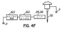
実際は、ルーパ214の位置は、その先端801が針132にかろうじて接触しているか、または針132から最小限に離間されるように調整されることが好ましい。このような位置の達成を容易にするために、図4Fで線図によって例示するように、電気式表示器回路820が設けられる。この回路820は、保持体214の中に取り付けられるルーパ216を含み、この保持体は次に、図4Dに示すように、軸218上の突縁220に電気絶縁体821を介して取り付けられる。保持体214はLEDまたは他の何らかの視覚的表示器822に電気接続され、この表示器は、保持体214と、枠台11上で接地電位に接続される電力供給源または電気信号源823との間で直列接続される。針132も接地電位に接続される。したがって、ルーパ216が針132に接触すると、表示器822および電力または信号源833を経由する回路が閉じられて表示器822を作動させる。
In practice, the position of the
作業者は、針132とルーパ216との間の開閉接点を見つけるように、ねじ812を前後に調整することによってルーパ216を調整することができる。次いで、作業者は、望ましいようにルーパをその位置のままにするか、またはどうにかして設定を撤回し、次いでねじ816をねじ込むことによってルーパ216を定位置に固定する。
The operator can adjust the
ルーパの調整を行うべきとき、針が零度または上部完全中央位置で機械10が停止され、その時点で制御装置19はステッチ要素をサイクルのループ捕捉時間位置(図4C)まで進めるが、そこではこれらの要素は停止し、機械は作業者がルーパを調整する安全装置モードに入る。針およびルーパの設定後、作業者からの入力によって、機械10の制御装置19は、ステッチを形成する方向とは異なる方向にルーパおよび針を移動させる。これは、針およびルーパ駆動サーボ機構67および69を逆に駆動して、針駆動軸32およびルーパ駆動部37を逆向きに回転してルーパおよび針のサイクルを後退させ、それによって針をその零度位置まで戻すことによって実現される。これはステッチの形成を防止するが、それが望ましいのはルーパ調整を型模様と型模様との間で実行するのがしばしば最適であるからである。ステッチ形成を防止することによって、ラインまたは経路に沿って縫製を継続することが望ましいか否かに関わらず、ルーパ調整はステッチラインに沿っていずれの箇所でも実行することができる。さらには、切り取られた糸の状態を述べる際に下で図5〜5Dに関連して説明するように、切り取られたルーパ糸および拭かれた上糸を保持する状態が保存される。
When the looper adjustment is to be made, the
単針縫製機械には多様な糸切り装置が使用されている。このような装置850が図5に例示されている。それは、空圧式であり得る往復直線アクチュエータ851を具備する。二重顎部の切断ナイフ852が、アクチュエータ851上を滑動するように取り付けられ、駆動時にはアクチュエータ851に向かって直線的に引っ込む。アクチュエータ851は次に滑動ブロック858(図5には図示しないが、図2Cの実施形態に示す)に取り付けられ、この滑動ブロックは、アクチュエータ851および関連組立体を、針プレート38の中の針穴に向かって駆動し、かつそれから遠ざかるように切断装置の駆動時にそのブロックが占有する位置に移動し、さらにルーパ216の通路から外れた休止位置まで戻す。ナイフ852は針糸用顎部854およびルーパ糸用顎部853を有し、これらのそれぞれは、アクチュエータ851の駆動時に上糸および下糸をそれぞれ引っかける。顎部853および854は共に刃先が付いており、その上でそれぞれの糸を切断する。静止鞘部材855がアクチュエータ851に固着されるが、その部材は滑動ナイフ852と協働して糸を切断するように構成された表面を有する。糸を切る際に、ナイフ852は、針糸の末尾は解放され得るが、下糸の末尾がナイフ852と鞘部材855の下部に固着されたバネ金属クランプ856との間に固締された状態に維持する引っ込み位置に停止される。このように固締すると、切断位置に近接し得る(それによってルーパ糸の末尾が非常に短くなり得る)ルーパの糸抜けを防止する。図5〜5Dは、垂直に配向された針を有する機械の中の組立体を例示する。しかし、機械10では、針132は水平に、すなわち、垂直材料平面16に対して垂直に配向され、他方ではルーパ216が、横断水平方向、すなわち、平面16に対して平行に揺動するように配向されており、ルーパ216の先端801は機械10の左側(図1におけるように正面から見て)を向く。
Various thread trimming devices are used in single needle sewing machines. Such a
図5Aは、針が水平に配向されている多針キルティング機械10の1つの種類のルーパ駆動部組立体26を示す。個別の型模様または型模様構成要素を構成するステッチの連鎖を縫い終わると、針132およびルーパ216は、キルティングされている布地12の針側で針132が材料から引き抜かれる図5Aに例示した位置で通常停止する。このようなステッチングサイクルの時点では、針糸222およびルーパ糸224が、キルティングされている材料12のルーパ側に存在する。針糸222は材料12から延びてルーパ216のルーパフック804の下を回って布地12に戻り、他方ではルーパ糸224が糸供給源856から延びて、ルーパフック804を貫通してルーパ216の先端801の穴から出て材料12の中に進入する。
FIG. 5A shows one type of
材料12のルーパ側では、複数のルーパヘッド26のそれぞれに切断装置850の1つが位置決めされ、それぞれが、適切な境界面(図示せず)を介してキルティング機械制御装置19の出力に接続された空圧式制御配管857を装備するアクチュエータ851を有する。個々の糸切り装置850自体は、単針縫製装置において従来技術で使用される糸切り装置である。
On the looper side of the
本発明によれば、複数の装置850が、本明細書で説明された様態で多針キルティング機械において使用される。図5および5Aを参照すると、多針チェーンステッチキルティング機械のそれぞれのルーパ組立体26では、装置850が、この装置850のナイフ852が、繰出し時にルーパ216と材料12との間に繰り出すように位置決めされ、キルティング機械の制御装置19のコンピュータ制御下で動作するように連結されている。図5Aに例示したように、糸切りが可能なサイクル時点にあるとき、制御装置19はアクチュエータ851を駆動し、アクチュエータ851は、図5Bに例示するように、ナイフ852が針糸およびルーパ糸を引っかけるように、ナイフ852を針糸222のループに通して移動させる。次いでナイフ852は針糸222および材料12から延びるルーパ糸224を切断するように引き込まれる。材料まで延びるルーパ糸224の切断された端と同じように、針糸222の分断された両端が解放される。しかし、ルーパ216まで延びるルーパ糸224の端は、図5Cに例示するように、固締された状態のままである。このような固締は、ステッチの再開時にループが形成されるようにルーパ糸の端を保持し、それによって、糸のチェーン形成が始まる前に予期し得ない数のステッチが失われる(それはステッチの型模様の中に欠陥を生じる)のを防止する。
In accordance with the present invention, a plurality of
縫製の開始時にステッチが失われるのを回避する追加的な保証として、万一ルーパ糸224の端が固締されなかった場合には、一連のステッチを開始するために、糸224の端が重力によって針の適切な側に配向されるようにルーパを配向する。このようにすると、縫われたタックステッチおよび型模様の始まりを構成する最初の数ステッチ以内にループができる確率が高い。
As an additional guarantee to avoid losing stitches at the start of sewing, in the unlikely event that the ends of the
上記の糸切り特性は、選択的に動作可能なヘッドまたは縫製ブリッジ上に別々にかつ個々に装着、脱着、または再配置が可能なヘッドを有する多針キルティング機械には特に有用である。個々の切断装置850にはそれぞれのルーパヘッド組立体が設けられ、ルーパヘッド組立体のそれぞれに関して着脱、装着、および移動が可能である。さらには、ヘッドが選択的に動作可能である場合には、この特性によって、それぞれの糸切り装置が別々に制御可能になる。
The above thread trimming characteristics are particularly useful for multi-needle quilting machines having selectively operable heads or heads that can be individually mounted, detached, or repositioned on a sewing bridge. Each
このような糸切り特性を補完するために、糸末尾ワイプ部材890が針ヘッド組立体25に設けられる。図5Cにさらに例示されているように、このワイプ部材890は、糸132に隣接して空圧式アクチュエータ892に枢支される針金フックワイプ要素891を具備して、針糸221の切断後に、このワイプ要素891を針132に対して垂直な水平軸回りに回転させる。アクチュエータ892は、駆動されると押え金皿158の内側でワイプ要素891を針132の先端回りに弧を描くように動かし、針糸221の末尾を材料12から材料12の針側まで、さらに押え金皿158の内側まで引っ張る。この位置からでは、縫製の開始時点で、上糸が押え金の下で固締されることはなく、したがって、糸末尾は、針が型模様の開始時に最初に下降するとき、典型的に材料12の裏側に直ちに押し込まれるようになっている。
In order to complement such thread trimming characteristics, a thread end wipe
図5Dは、縫製機械の個々の糸に同じように加えられ、上記で説明した多針キルティング機械の個々の糸のそれぞれに特に適切である糸張力制御システム870を例示する。糸、例えば、ルーパ糸224は、典型的には糸供給源856から、糸に摩擦を与えて糸を緊張させる糸緊張装置871を経由して、下流側、例えば、ルーパ16に達する。この装置871は、糸224の張力を制御するように調整可能である。本システム870は糸張力モニタ872を具備し、この糸張力モニタ872を介して糸224が張力調整器871とルーパ216との間に延びる。モニタ872は1対の固定糸案内873を具備し、糸は、この固定糸案内873間を駆動され、さらに横方向力変換器876に支持された駆動アーム875上のセンサ874によって横方向に逸らされるが、この変換器は、糸張力測定値を生成するために、張力を受けた糸224によってセンサ874に掛かる横方向の力を測定する。糸222および224のそれぞれには、このような糸張力制御装置が設けられる。
FIG. 5D illustrates a thread
糸張力信号は、変換器876によって出力されて制御装置19に送信される。制御装置19は、糸224の張力が適正であるか否か、またはそれが緩すぎないかそれとも張りすぎていないかを判定する。糸張力調整器871には、張力調整を実行するモータまたは他のアクチュエータ877が設けられる。アクチュエータ877は、制御装置19からの信号に応答する。制御装置19が、変換器876からの張力測定信号に基づいて、糸224の張力を調整すべきであると判定すると、制御装置19はアクチュエータ877に制御信号を送信し、それに応答してアクチュエータ877は張力調整器871に糸224の張力を調整させる。
The yarn tension signal is output by the
図5Cに例示したように糸末尾ワイプ部材890、または糸の切断後、および新たな箇所で縫製を再開する前に、自由な切断上糸を引っ張るための他の機構を使用する代わりに、糸末尾ワイプ機能の結果を実現する機械制御シーケンスを実行することが可能である。図5Eは、型模様構成要素の縫製の終わりにタックステッチシーケンスが実行された直後における糸の切断完了前の上糸222の状態を例示する。上糸222は、上糸供給源401から、制御装置19の出力によって制御されたアクチュエータ403によって動作する上糸張力調整器402を介して、針の目に達して針132まで延びているように示されている。張力調整器402と針132との間で、上糸222は、同様に制御装置19の出力によって制御されるアクチュエータ406によって駆動される押出し器405を具備する引出し機構404を通過する。図5Eは、押出し器405が、その引っ込み位置にあるところを実線で示す。アクチュエータ406が駆動されると、押出し器405は、その繰出し位置407(破線によって例示する)まで移動し、同様に破線で例示する位置まで上糸を引っ張る。、上糸引出し機構404がパルス入力(pulsed)されている短い時間間隔の間、上糸222の張力を解放するように上糸張力調整器402のアクチュエータ403に信号を送信する制御装置19によって上糸の引出しが行われる。糸引出し機構404のパルス入力は、制御装置19から、たるんだ上糸の長さを上糸供給源401から引き出すために、押出し器405に上糸222を逸らせる引出し機構404のアクチュエータ406に送信された信号によってもたらされる。代替的に、上糸のたるみの長さを引っ張って、針132と材料12との間の糸末尾の長さを追加するために針132に通して引っ張るように、針132を材料12に対して約数インチの短い距離だけ移動させることができる。このような相対的な動きは、ウェブ12を前進させることによって、もしくはブリッジ21、22を移動させることによって、または両方によってもたらすことができる。
Instead of using the thread end wipe
上述に説明したように、上糸222が引き出された後で、糸222および224は切断され、ルーパ糸は、図5Cに関連して上で説明したように固締される。しかし、この実施形態では、ワイプ機構890は存在する必要がない。その代わりに、ワイプ動作が利用可能である。手順中のこの時点では、上糸末尾は、針132から延びて、材料12の下を通過して材料の下方に達し、図5Fに例示するように、その末尾が切断され、糸張力が上糸に再び印加される位置まで達する。次いで、針132は、材料12に対して新たな開始位置410まで前送りされ(すなわち、ブリッジもしくは材料のいずれか、または両方を移動することが可能であり)、図5Gに例示したように縫製を再開するために糸を材料の上部に運ぶ。
As explained above, after the
次いで、この時点の前にワイプ部材890が使用されたか否かに関わらず、上糸タックサイクルが実行され、そこでは縫製ヘッドが1ステッチサイクルを通して動作し、そのタックサイクルは、上糸末尾を材料12に通して材料12の下方に突き出し、そこで、図5Hに例示するように、その末尾はルーパ216によって捕捉される。次いで、上糸222の張力が張力調整器402の駆動によって先行して加えられたとき、針132は、材料12に対して糸をワイプする動作で、図5Iに例示するように、糸が材料12を貫通した開始位置410から離れ、かつそこへ戻るように移動される。このような動作では、制御装置19は、縫うべき型模様を読み取ることによって方向を選択する。このような動作は、上糸末尾を再び材料から引っ張り出すことなく、残っている上糸末尾を材料12の下部すなわちルーパ側へ引っ張るのに十分である。このような動作の長さは異なる用途ごとに様々であり得る。
Then, regardless of whether the wipe
動作経路は、例えば、直線、円弧、三角形、直線と円弧の組合せ、または位置410から針を約2インチ前後移動させる他の何らかの動きもしくは組合せであり得る。機械が切断するように設計またはプラグラムされている糸末尾の長さに応じて、様々な経路長さが使用可能である。このような経路は、針132にできる上糸のたるみがいずれも、糸が縫製型模様の中に捕捉されるかまたは針132に当たるのを回避する型模様経路の脇に位置するように配向されることが好ましい。この機械10では、このような動作は、材料12が静止状態に維持され、かつブリッジ21、22を材料12の平面に対して平行な経路の中で移動させることによって実施されることが好ましい。タックサイクルの終わりでは、機械は図5Jに示す位置にある。
The motion path can be, for example, a straight line, an arc, a triangle, a combination of a straight line and an arc, or some other movement or combination that moves the needle back and forth about 2 inches from
型模様の開始時には、縫製要素、針132、およびルーパ216が、針糸222およびルーパ糸224が他方の糸によって形成されたループを交互に捕捉してチェーンステッチの形成を開始するように協働する必要がある。ステッチサイクルが縫製シーケンスの途中で実行されるとき、すなわち、一旦連鎖が始まったら、針132は材料12を貫通して降下し、ルーパ216と上糸222とルーパ糸224との間に形成されたループ412(時々、三角形(triangle)と呼ばれる)を捕捉するが、このループの形成は、図5Kに例示するように、リテーナまたは延展機234の動作によって容易になる(さらに完全な説明には、特許文献1の図5Fを参照されたい。当特許文献1の図5A〜5Gは、通常のチェーンステッチ形成サイクルを連続的に例示したものである)。しかし、糸はまだ材料12の中に配置されていないので、ルーパ糸224は、針プレート38の下方およびリテーナ234の下方で終端している。具体的には、ルーパ糸224は切断ナイフ852とばねクランプ856との間に固締されている(図5J)。したがって、三角形412は、まだその通常の形では存在しておらず、このループが針132によって捕捉されることは必ずしも完全に予測が付くわけではない。したがって、第1のステッチが欠損する可能性が高い。さらに重要なことは、第1のステッチが形成されるとき、幾つかの不確定数のステッチサイクル後まで、それぞれの後続ステッチが欠損するという許容できない可能性が存在することである。これは、欠陥製品または処分製品をもたらす恐れがあり、製品を補修または廃棄する必要があり得る。
At the start of the pattern, the sewing element,
型模様の縫製を開始するときのステッチ形成の確実性は、針が下糸のループを捕捉する前に、ルーパが上糸のループを捕捉するように糸を操作することによって大幅に向上することが判明した。これは、ルーパ糸の末尾を再誘導することによって実現可能である。さらに確実にするには、このことは、ステッチ要素のタイミングを相互に対して変更すること、すなわち、最初に捕捉されるループが上糸のループ(それは前進してくるルーパによって捕捉される)であるようにルーパのタイミングに対して針のタイミングを変更することによっても実現可能である。このことは、次に、針の最初の下降時に、針が下糸ループを逸するように糸を操作するか、またはステッチ要素のタイミングを計ることによって実行可能である。これを実行可能にする1つの方法は、針の最初の下降時に、確実に針が下糸の「間違った」側を通るようにすることである。下糸は、ルーパ糸の末尾がルーパの先端から戻って針のルーパ側に沿って延びるときに、針の「間違った」側にある。 Stability of stitch formation when starting to sew a pattern is greatly improved by manipulating the thread so that the looper captures the upper thread loop before the needle captures the lower thread loop. There was found. This can be achieved by redirecting the end of the looper yarn. To be more certain, this means that the timing of the stitch elements is changed relative to each other, i.e. the first captured loop is the upper thread loop (it is captured by the advancing looper) It can also be realized by changing the needle timing with respect to the looper timing. This can then be done by manipulating the thread so that the needle escapes the bobbin thread loop or timing the stitch elements during the initial lowering of the needle. One way to make this feasible is to ensure that the needle passes the “wrong” side of the bobbin thread when the needle is first lowered. The lower thread is on the “wrong” side of the needle when the end of the looper thread returns from the looper tip and extends along the needle looper side.
縫製を開始する前に、針132が材料12に対して新たな位置まで移動されると、上糸222が針132の目を通って、糸巻きから糸末尾まで延びている状態で針132は材料12の上方にある。通常のステッチサイクルでは、針132は、図5Lに示すように、材料の上から始まり、ルーパ216は図示のように前送りされている。ルーパ糸224の末尾は、針プレート38の下方およびリテーナ234の下方にある。従来の始動では、可能性として、しかし必ずしもそうであるとは限らないが、針132が下降して、図5Mに例示するように、下糸224とルーパ216との間を通過し、図5Nに例示するように下糸のループを捕捉するので、ルーパ216は引き込むことになる。このことは、ルーパ糸224が、図5Oに例示するように、リテーナ234の下方でルーパ216に近接する針糸222に巻き付くことになり、針132の次の下降時にループを逸する可能性が増大する変形した三角形をもたらす。
If the
本発明の一実施形態によれば、針駆動部およびルーパ駆動部は、図5Lの開始位置と同様である図5Pの開始位置にあるときに切り離され、針は、上部完全中央位置に保持される。ルーパ駆動部は、次いで2分の1サイクル進められ、ルーパ216は図5Qに例示した位置まで移動し、それによってルーパ216を針132の経路から引っ込める。次いで、ルーパ駆動部はその半サイクル位置に保持され、他方で針駆動部が作動されて、針132をその半サイクル位置まで下降させるが、それによって針132を、図5Rに例示するように、下糸224から離れた状態に残す。次いで、針駆動部およびルーパ駆動部が再び互いに結合され、同期して互いに前送りされ、その時点でルーパ216は、図5Sに例示するように、ステッチサイクルのほぼ4分の3の位置で針のループを捕捉し始め、その位置から、図5Tに例示するように、完全サイクル位置まで進む。次いで、これらの要素は次のサイクルを通して移動を継続し、そこでは、図5Uから5Xまでに例示するように、ステッチの形成を観察することができる。ほぼ図5Xにおける位置によって、ルーパ糸の末尾は、糸切り装置の固締作用から脱し終えることになる。
According to one embodiment of the present invention, the needle drive and looper drive are disconnected when in the start position of FIG. 5P, which is similar to the start position of FIG. 5L, and the needle is held in the upper fully central position. The The looper drive is then advanced by one-half cycle, and the
説明したように、開始時の針駆動部およびルーパ駆動部の分離は、開始時のステッチの欠損を回避する。針駆動部サイクルおよびルーパ駆動部サイクルの分離は、糸切りを容易にする際のように他の用途を有する。 As explained, the separation of the needle drive and the looper drive at the start avoids missing stitches at the start. The separation of the needle driver cycle and the looper driver cycle has other uses, such as in facilitating thread trimming.
上記で説明した分離開始方法の利用に代わる代替として、開始時にステッチが欠損する可能性は、上糸のループがルーパによって捕捉される前に、下糸のループが針によって捕捉されるのを防止するために、ルーパ糸の糸末尾を再誘導または案内することによって低減され得る。このような再誘導は、糸切り装置およびクランプ850(図5J)を位置移動または他に位置決めし、ルーパ糸224の末尾をルーパ216の針側から遠ざけることによって実現可能である。糸押出し機構または他のルーパ糸再誘導技法を使用して、針が下糸ループを捕捉する前に、ルーパに上糸ループを捕捉させることができる。
As an alternative to using the separation initiation method described above, the possibility of missing stitches at the start prevents the lower thread loop from being captured by the needle before the upper thread loop is captured by the looper. In order to do this, it can be reduced by redirecting or guiding the end of the looper yarn. Such redirection can be accomplished by moving or otherwise positioning the thread trimming device and clamp 850 (FIG. 5J) and moving the end of the
開始時にステッチを欠損させる可能性を増大する別の現象は、延展機またはリテーナ234が、ルーパ糸224が針プレート34および材料12に向かって引き寄せられるまで、ルーパ糸224によって三角形を形成できないことである。糸切り装置850によって固締されているルーパ糸224は、リテーナ234の届かないところに保持されている。縫製が開始される前に、かなりのルーパ糸のたるみが、ルーパ216と糸切り装置850におけるクランプ位置との間のルーパ糸末尾に生じる可能性がある。このようなたるみは、針からルーパの反対側まで揺れ動く大きなループを形成し、針が最初に下降した後であっても、所与のサイクルでステッチが捕捉される可能性を低減させ、それによってステッチチェーンの開始を予測不能に遅らせる恐れがある。このような遅れは、縫製型模様に許容できないほどの長いギャップをもたらし、パネルの補修または廃棄が避けがたい。このルーパ糸のたるみが原因でこのような問題が生じる可能性は、ルーパ糸を制限することによって低減可能である。このような制限は、図5Yに例示するように、針プレート38の下方にルーパ糸デフレクタ430を設けることによって実現可能である。糸デフレクタ430のような構造は、開始時にルーパ216を離れるルーパ糸224の末尾の方向を制御し、さらにルーパが針糸ループを捕捉した後に針132がルーパ糸ループを逸することがないように、ルーパ糸の末尾とルーパの間隔取りに影響を与えるように配置され得る。このようなルーパ糸デフレクタ430としての構造は、分離開始技法(split start technique)が使用されるか否かに関わらず、ステッチ形成の確実性を向上させる。幾つかの場合では、確実性の向上が分離開始特徴を割愛できるほどに十分である。
Another phenomenon that increases the likelihood of missing stitches at the start is that the spreader or
図5Yに例示したルーパ糸デフレクタ430は楔状の形態であり、針プレート38の下部に固定される。デフレクタ430の楔は、ルーパがその零度付近の前送り位置または図5Pに例示した針上げ位置に進むとき、ルーパ216の先端の経路に近接して位置決めされるテーパ表面431を有する。この位置では、型模様の開始時に、ルーパ糸末尾が針経路の反対側で針切り850に固締される。デフレクタ430の表面431は、一旦ルーパが針糸ループを捕捉したら、下降してくる針132が次の下降でルーパ糸ループを捕捉するようにルーパ糸224がルーパ216の針側にある可能性が非常に高くなるように、ルーパ糸の末尾を十分に針プレートから離して案内するように、ルーパの経路に対して位置決めされる。ルーパ糸デフレクタ430は、上で説明した分離開始方法が使用されないかまたは使用できないときに、開始時におけるステッチの欠損の低減に寄与する。
The
図5Yはまた、図4Dにより適切に例示されているように、ルーパ216の基部部分805に取り付けられた従来の針ガード460を例示する。この針ガードは、ルーパ216を軸にそれを枢動させることによって調整可能であり、その場合に、針ガードは、図4Dの穴461の中の止めねじ(図示せず)によって定位置に固定可能である。この針ガード460は、下降してくる針132を前進してくるルーパ216の右側にぶれないように保ち、図5Rおよび5Sに例示したように、針をルーパの左側に維持し、ルーパ216がループを捕捉してステッチをとばさないようにしている。
FIG. 5Y also illustrates a
改良された代替的な実施形態が図4Gに例示されているが、そこでは、二重針ガード組立体470が設けられている。この組立体470は、第1の針ガード471および第2の針ガード472を含む。第1の針ガード471は針ガード460と同様な働きをし、同じようにルーパ216の基部805に調整自在に枢支される。第2の針ガード472は円形状断面の棒であり、針プレート38のルーパ側に剛着された取付けブロック473の穴の中に回転可能、かつ調整自在に取り付けられる。4Gの実施形態では、糸デフレクタ430も取付けブロック473に装着される。針ガード472は、ルーパ216が針糸222の右側を通過せず、それによって上糸ループを逸し、したがってステッチをとばすのではなく、針糸222と針132との間を通過するように(図5S)、下降してくる針132が前進してくるルーパ216の左側にそれ以上ぶれないように保つ。第2の針ガード472の円形断面は、ルーパの動作平面および針プレート平面に対して平行であり、すなわち、説明の機械において水平で、横方向の配向にある軸474上に中心が位置する。針ガード472は、軸474から離間されるが、軸474に平行な軸476を有し、ブロック473の穴の中に取り付けられる偏心基部475を有する。したがって、針ガード472は、このガードおよびその軸474を針132に向かってまたは針132から離して移動させるように、ブロック473の取付け穴の中で回転自在に整可能であり、このガードはブロック473上にアレンヘッド式ねじ477をねじ込むことによって定位置に固定され得る。
An improved alternative embodiment is illustrated in FIG. 4G where a double needle guard assembly 470 is provided. The assembly 470 includes a first needle guard 471 and a
タックステッチシーケンスをステッチする際に、特にタックステッチシーケンスの開始時に、ステッチの欠損の可能性を低減するために使用される技法も改良される。開始時タックステッチシーケンスは、所定の型模様の方向に約1インチの短い距離だけ縫うことによって開始され、次いで、ステッチの同じラインの上を前に向かって進む前に、最初のステッチの上を開始位置まで縫い返されることが好ましい。始めに、数インチの長さのステッチが縫われ、次いで通常長さのステッチが続く。典型的な通常のステッチ率は1インチ当たり7ステッチであり得る。タックシーケンスを開始するために、糸は最初に型模様曲線の原点に設定されるが、それには上で説明した、ワイプおよびタックサイクルを利用することによって行うことができる。次いで、2つの3倍長さステッチを縫うことが可能であり、その後に、型模様曲線ラインに沿って原点から離れる方向へ単一の通常長さのステッチが続く。次いで、7つの通常長さのステッチを原点まで縫い返すことができる。次いで、縫い方向が再び反転され、型模様曲線に沿って最初のステッチの上を縫うことができる。 Also improved is the technique used to reduce the likelihood of stitch loss when stitching a tack stitch sequence, particularly at the beginning of the tack stitch sequence. The starting tack stitch sequence begins by sewing a short distance of about 1 inch in the direction of a given pattern, and then moves over the first stitch before moving forward on the same line of stitches. It is preferable to sew back to the start position. First, several inches long stitches are sewn, followed by normal length stitches. A typical normal stitch rate may be 7 stitches per inch. To initiate the tack sequence, the yarn is initially set to the origin of the pattern curve, which can be done by utilizing the wipe and tack cycle described above. Two triple length stitches can then be sewn, followed by a single normal length stitch along the pattern curve line away from the origin. Seven normal length stitches can then be stitched back to the origin. The sewing direction is then reversed again, and the first stitch can be sewn along the pattern curve.
型模様を通常に縫う際には、ブリッジまたは材料の送出し、もしくはその組合せは、材料に対してステッチ要素の連続的な送出し動作をもたらすことが好ましい。しかし、タックシーケンスでは、特に、通常のものよりも長いステッチが使用されるタックシーケンスの当該部分では、得られる送出しは断続的である。しかし、このような断続的な送出しは、急激でないことが好ましく、むしろ、針が材料から離れているときのステッチ要素と材料との間における急激な相対動作と、針が材料に係合されているときの相対的にそのような急激さがほとんどまたは一切ない動作との間を円滑に移行することによって行われる。通常長さのステッチを縫うときには、長いステッチを縫う前であろうとまたはその後であろうと、送出しは連続的かつ円滑であることが好ましい。 In normal sewing of the pattern, the delivery of bridges or materials, or a combination thereof, preferably results in a continuous delivery operation of the stitch elements relative to the material. However, with a tack sequence, the resulting delivery is intermittent, especially in those portions of the tack sequence where longer stitches are used than usual. However, such intermittent delivery is preferably not abrupt; rather, a sudden relative movement between the stitching element and the material when the needle is away from the material and the needle is engaged with the material. This is done by smoothly transitioning between operations with relatively little or no such abruptness. When sewing normal length stitches, delivery is preferably continuous and smooth, whether before or after the long stitches are sewn.
一般に、型模様をキルティングする際の高速縫製は、連続刺繍、すなわち、時間または少なくとも縫われた距離の関数として正弦的である針の動きによって実行される。上記で言及した、いわゆる断続送出し時では、針の動きは、距離の関数として非正弦的であると見なすことが可能であり、針の往復動は、針が材料を貫通するときは正弦曲線よりも速く、針が材料から引き抜かれるときはそれよりも遅い。針の速度の移行は円滑であり得る。この種の針速度の変更は、反転が型模様を縫う際に使用されるときには常に有用である。縫製が、材料に対して停止状態から動作する針によって始まる場合は、このような針駆動動作が有益であるもう1つの事例である。タックステッチは、両状況に共通する実施例であり、そこではこのような針速度の変更が望ましい。 In general, high-speed sewing in quilting a pattern is performed by continuous embroidery, ie needle movement that is sinusoidal as a function of time or at least the distance sewn. At the so-called intermittent delivery mentioned above, the needle movement can be considered non-sinusoidal as a function of distance, and the needle reciprocation is sinusoidal when the needle penetrates the material. Faster and slower when the needle is withdrawn from the material. The needle speed transition can be smooth. This type of needle speed change is always useful when reversal is used when sewing a pattern. Such a needle drive operation is another case where sewing starts with a needle operating from a stationary state on the material. Tack stitching is an example common to both situations, where such a change in needle speed is desirable.
例えば、針速度は停止から始まり、時間の関数として正弦的な動きで連続サイクル速度に達し得るが、材料および針の相互に対する送出しは、針が材料から引き抜かれるときにはより速く、針が材料を貫通しているときにはより遅くなり、材料に対して移動した距離に関して非正弦的な針の動きを与える。このような動きでは、平均的なものよりも少し大きなステッチを縫うことが可能であり、次いで、針が材料を貫通する合間の材料の送出しは、連続刺繍が継続し得る通常のステッチ間隔まで徐々に低減可能である。次いで、タックを実行する際には、材料に対する針の方向が反転され、非正弦的な針の動きによって、通常のものよりも少し長いステッチの同様のシーケンスが実行され、それに続いて通常サイズのステッチに移行する。方向の反転が行われるときには常に同様の手法が使用可能である。これは、不格好なステッチ、ステッチの欠損、および糸の切断を低減させる。材料に対する針の移動は、(1)材料を静止状態に保ちながら、機械の枠台に対してブリッジを移動させることによって、(2)材料を移動させながら、機械に対してブリッジを静止状態に保つことによって、または(3)機械の枠台に対するブリッジおよび材料の相対移動を組み合わせることによって実行することができる。 For example, the needle speed may start from a stop and reach a continuous cycle speed with a sinusoidal movement as a function of time, but the delivery of the material and needle to each other is faster when the needle is withdrawn from the material and the needle removes the material It is slower when penetrating, giving a non-sinusoidal needle movement with respect to the distance traveled relative to the material. With such movements, it is possible to sew stitches that are slightly larger than the average one, and then the delivery of the material between the time the needle penetrates the material, up to the normal stitch spacing where continuous embroidery can continue It can be gradually reduced. Then, when performing a tack, the direction of the needle relative to the material is reversed, and a non-sinusoidal needle movement performs a similar sequence of stitches that are slightly longer than normal, followed by a normal sized Transition to stitches. A similar approach can be used whenever direction reversal occurs. This reduces clunky stitches, stitch defects, and thread breaks. The movement of the needle relative to the material can be achieved by (1) moving the bridge relative to the frame of the machine while keeping the material stationary, and (2) keeping the bridge stationary relative to the machine while moving the material. It can be performed by keeping or (3) by combining the relative movement of the bridge and material with respect to the frame of the machine.
上記で言及した移動は、機械構成要素および材料の慣性ばかりでなく、材料の変形および加速、減速、針の歪み、ならびにこれらの効果を最適化または最小化する他の要因も考慮するような方法で実行され得る。例えば、型模様の本体内部の通常の縫製では、針は、材料と針との間の相対移動(それは材料の平面に平行な移動である)が連続的な状態で、すなわち、一定速度で一連のステッチサイクルを通じて正弦曲線的に往復動し得る。この実施例では、針は1分間に1400サイクルで往復動し、材料に対する針の移動は1分間に200インチである。次いで、タックシーケンスを縫うべきときは、このような平行移動および往復動する針の動作速度は、例えば、1秒間に100インチおよび1分間に700サイクルにそれぞれ比例して減速され得る。次いで、タックステッチでは、最小限の針の撓みおよび最小限の材料の変形で、通常長さのステッチまたは通常のものよりも長いステッチを縫うために(制御装置が命令し得るように)、往復動する針の動作速度は、例えば、針が材料を貫通しているときのサイクル部分では1秒間に2100サイクルの速度で移動し、次いで材料を貫通する合間では1秒間に数百サイクル以下まで減速することによって変更され、かつ非正弦的に移動され得る。したがって、往復動する針動作は、材料を貫通しているときにはより大きなサイクル速度まで加速され、ステッチを貫通する合間ではより遅いサイクルに減速される。移行ステッチが、通常ステッチに移行するか、またはそれから移行するために、タックステッチの前または後に縫われ得る。このようなシーケンスは、タックステッチ縫いに、または方向反転を型模様の中に縫われるときは常に使用可能である。 The movement referred to above is not only a mechanical component and material inertia, but also a method that takes into account material deformation and acceleration, deceleration, needle distortion and other factors that optimize or minimize these effects. Can be executed in For example, in normal sewing inside the body of the pattern, the needles are in a series of relative movements between the material and the needles (which are movements parallel to the plane of the material), i.e. at a constant speed. It can reciprocate sinusoidally throughout the stitch cycle. In this example, the needle reciprocates at 1400 cycles per minute and the needle movement relative to the material is 200 inches per minute. Then, when the tuck sequence is to be sewn, the speed of movement of such translation and reciprocating needles can be reduced, for example, in proportion to 100 inches per second and 700 cycles per minute, respectively. The tuck stitch then reciprocates to sew a normal length stitch or a longer stitch than usual (with the control device can command) with minimal needle deflection and minimal material deformation. The moving speed of the moving needle, for example, moves at a speed of 2100 cycles per second in the cycle part when the needle is penetrating the material, and then decelerates to several hundred cycles or less per second between the penetrating materials. And can be moved non-sinusoidally. Thus, the reciprocating needle motion is accelerated to a higher cycle speed when penetrating the material and decelerated to a slower cycle between penetrating stitches. Transition stitches can be sewn before or after tack stitches to transition to or from regular stitches. Such a sequence can always be used for tuck stitch sewing or when direction reversal is sewn into the pattern.
機械10は、図6に模式的に例示する動作システム20を有する。ブリッジ21、22は、動作システム20のブリッジ垂直動作機構30を介して別々にかつ個々に枠台11上を垂直に移動可能である。ブリッジ垂直動作機構30は、枠台11に搭載された2つの昇降機またはリフト組立体31を、1つは枠台11の右側にまた1つはその左側に具備する(図1A参照)。リフト組立体31のそれぞれは、2対の静止垂直レール40を枠台11のそれぞれの側に1対具備し、これらのそれぞれの上に2つの垂直可動架台41が乗り、1つは垂直ブリッジ昇降機(下部ブリッジ昇降機33および上部ブリッジ昇降機34を含む)の2つのそれぞれに割り当てられる。昇降機33、34のそれぞれは、レール40に乗る支持ブロック42が装備される2つの垂直可動架台41(枠台11のそれぞれの側に1つ)を具備する。昇降機33、34のそれぞれの架台41は、それぞれのブリッジの両側を支持して概ね長手水準、すなわち、前後水準に留まるようにレール40の上に取り付けられる。
The
上部ブリッジ22は、上部昇降機34の架台41のそれぞれの右側および左側で、その対向する左端および右端が支持され、他方で下部ブリッジ21は、下部昇降機33のそれぞれの右側および左側架台41上に、その対向する左端および右端が支持される。昇降機架台41のすべては機械的に別々に移動可能であり、昇降機33、34のそれぞれの対向する架台は、同時に昇降するように制御装置19によって制御される。さらには、昇降機33、34は、ブリッジ21、22を横断水準、すなわち、横方向に維持するために、それぞれのブリッジ21、22の両端で架台41を同期して移動するように制御装置19によって制御される。
The
線形サーボモータ固定子39が、枠台11のそれぞれの側に取り付けられ、垂直に、すなわち、垂直レール40に平行に延びる。線形サーボモータ35、36のそれぞれの電機子が、下部および上部昇降機33、34のそれぞれの架台41上に固着される。制御装置19は、ブリッジ21の両端を水平に維持しながら、固定子39上で下部ブリッジ21を昇降させるように下部サーボ機構35を制御し、さらにブリッジ22の両端を水平に維持しながら、同じ固定子39上で上部ブリッジ22を昇降させるように上部サーボ機構36を制御する。垂直動作機構30はデジタルエンコーダまたはレゾルバ50を具備し、それぞれの昇降機によって1つが担持され、レール40上の架台41の位置を厳密に測定して、ブリッジ21、22の精確な位置決めおよび水平化を補助するために情報を制御装置19にフィードバックする。線形サーボ機構のような線形モータが好ましいが、ボールねじおよび回転サーボ機構、または他の駆動装置などの代替による駆動部が使用可能である。エンコーダ50は、実際の位置信号を出力するアブソルートエンコーダであることが好ましい。
Linear
動作システム20は、ブリッジ21、22のそれぞれに横断水平動作機構85を具備する。ブリッジ21、22は、その右側および左側に、その両端から剛性に延在する1対の舌部49を有し、それらはブリッジ21、22を昇降機33、34の架台41上で支持する。舌部49は、横断水平ブリッジ動作機構85が動作する際に昇降機架台41上を横方向に移動する。ブリッジ21、22のそれぞれの上の舌部49は、それぞれの昇降機33、34の架台41上の軸受け43に乗るレールの形態にある横方向に延びる案内構造44を担持する(図6Aおよび6G)。線形サーボ固定子バー60が、ブリッジ21、22のそれぞれの一方の側の舌部49に固定され、レールまたは案内構造44に対して平行に延びる。固定子バー60と協働し、かつ制御装置19からの信号に応答してそれを横方向に移動させるように位置決めされた線形サーボ機構45、46の電機子が、それぞれ各々のブリッジ21、22の架台41の一方に固定される。この横断水平動作機構は、横方向ブリッジ位置の厳密な制御を補助するためにブリッジ位置情報を制御装置19にフィードバックするために、それぞれの昇降機41上のサーボ機構45、46の電機子に隣接して設けられる、ブリッジ21、22のそれぞれのためのデコーダ63を具備する。ブリッジ21、22は、垂直方向すなわち、上下、および横断方向、すなわち左右に移動するように個別制御可能であり、材料12上のキルト型模様をステッチするために協働様態で動作する。例示の実施形態では、それぞれのブリッジは、横方向に18インチ(その中心位置から+/−9インチ)移動可能であり、それぞれのブリッジは、上下に36インチ(その中心位置から18インチ)移動可能である。下部および上部ブリッジ21、22の垂直動作の範囲は重なり得る。
The
枠台11の頂部の駆動ローラ18(これらは動作システム20全体の一部でもある)は、図6に例示するように、枠台11の頂部の送出しサーボモータ64によって枠台11の右側(下流側に面する)で駆動される。サーボ機構64は、駆動されるとき、材料12のウェブを下流側に送り出し、キルティング台を通過する平面16に沿って、かつブリッジ21および22の両方の部材23と24との間でウェブを引き上げるローラ18を駆動する。ローラ18はさらに、図6Aに例示するように、機械10の左側の、枠台11の中に配置されたタイミングベルト65を駆動する。ブリッジ21、22のそれぞれには、遊びローラ15の代わりに、それぞれのブリッジ21、22が支持されているそれぞれの昇降機架台41に軸支される1対のピンチローラ66も設けることができる。これらのローラ66は、縫製ヘッド25、26の水準で材料が横方向に位置移動するのを最小化するために、ブリッジ21、22の水準で材料12を把持する。ピンチローラ66は、ローラ66対のニップで、それらの表面の接線動作が材料12と一緒に動くようにベルト65によって同期化される。
As illustrated in FIG. 6, the driving
遊びローラ15のみを優先してローラ66を割愛することも、許容可能な代替案であることが判明している。このような代替案は、一定の材料およびブリッジの動作シーケンス時における材料の集群を回避するために望ましい場合がある。
It has been found that omitting the roller 66 in favor of only the
図6Aに例示するように、昇降機架台41はブリッジ21、22を静止状態に支持しているが、モータ64を作動すると、ウェブ12を下流側にかつブリッジ21、22のピンチローラ66の間を上向きに前進させるようにローラ18を駆動する。次いで、ローラ18は、ベルト65を駆動する、枠台11の左側のベルト駆動はめ歯車600を回転させる。ブリッジ21、22の両方のローラ66は、ローラ18の動作によって材料12が上に移動されると材料12と一緒に転動するようにブリッジ21、22が垂直に固定されるとき、これらのローラが同じ接線速度を有するようにベルト65の動作によって駆動される。他方では、送出しローラ18および材料12が静止しているとき、ベルト65は、図6Bに例示するように静止状態に留まる。ベルト65が静止している状態で、両方のブリッジ21、22が上下に移動すると、ローラ66がウェブ12に対して、さらにベルト65に対して押し動かされる。ベルト65に対してローラ66が移動すると、ローラ66が材料12の静止ウェブの表面に沿って転動するように、ローラ間のニップにおけるローラ表面をウェブ12において静止状態に保つ速度でローラ66を回転させる。さらには、ウェブ12の動作とブリッジ21、22の動作を組み合わせると、ローラ66の対のニップにおけるローラ66の表面が常に材料12と一緒に動くようにブリッジ21、22の上昇動作をウェブ12の上昇動作から実質的に減ずる、ローラ66に付与される組合せ動作が伴う。このようなウェブ12とブリッジ21、22のそれぞれのピンチローラ66との間の同期化された動作は、材料12上の長手方向の引っ張りを維持し、ブリッジ21、22のそれぞれにおいて材料12を固締して、ウェブ12の横方向の材料変形に耐える。
As illustrated in FIG. 6A, the
ベルト65がピンチローラ66の動作をブリッジ21、22の動作およびウェブ12の動作と同期化するのを可能にする構造が、図6Cおよび6Dばかりでなく、上記で説明した図6Aおよび6Bにも例示されている。ベルト65は、送出しローラ18によって歯車組立体601(図6D)を介して駆動されるはめ歯車600回りに延びる。ベルト65はさらに、静止枠台11に回転自在に装着された4つの遊びプーリ602〜605回りに延びる。ベルト65はまた、共に下部ブリッジ21用の昇降機架台41に回転自在に装着された被動プーリ606および遊びプーリ607回りに、さらに、共に上部ブリッジ22用の昇降機架台41に回転自在に装着された遊びプーリ608および被動プーリ609回りに延びる(すべて枠台11の左側)。被動プーリ606はベルト65の動作によって駆動され、それは、次に歯車機構610(図6D)を介して、下部ブリッジ21のピンチローラ66を駆動し、他方で被動プーリ609(同様にベルト65の動作によって駆動される)は、歯車機構611を介して、上部ブリッジ22のピンチローラ66を駆動する。歯車機構610および611は、ローラ66およびローラ18の接線速度が、ウェブ12の速度に対して零であるように、駆動歯車機構601の駆動比に関連付けられた駆動比を有する。ベルト65の経路は、ブリッジ21、22の位置に関わらず同じ位置に留まることに留意されるべきである。
A structure that allows the
さらには、図6Dの下部および図6Eおよび6Fに、入口ローラ15がローラ18と同様の1対のローラとして示されている。このようなローラ15がそのように設けられて駆動される場合は(それらは、機械10の上流側のウェブ12用の送出しシステムに応じて望ましい場合もあるが、望ましくない場合もある)、このようなローラ15も、ベルト65によって駆動されるローラ605によって駆動される歯車機構612を同様に介して、ベルト65によって駆動されるべきである。そのような場合に、ローラ15は、機構601と612との間で適切に一致させた歯車比によって、送出しローラ18と同じ接線速度に維持されるべきである。しかし、ローラ15を遊びローラとして自由に回転可能にし、さらに材料12の上方およびその上流側に単一のローラ15のみ(その回りに材料12が延びる)を設けることが好ましい場合もある。歯車機構601、610、および611のそれぞれは、歯車機構612に関して実質的に例示しかつ説明した通りでよい。
Furthermore, the lower part of FIG. 6D and FIGS. 6E and 6F show the
ブリッジ21、22の垂直動作は、制御装置19によって、材料12のウェブの下流側の動作と連係される。この動作は、ブリッジ21、22が、それらの36インチの垂直移動範囲内に効率よく留まり得るような方法で連係される。さらには、2つのブリッジ21、22は、異なる型模様または型模様の異なる部分を縫うように移動可能である。したがって、ブリッジ21、22の別々の動作はまた、両方のブリッジ21、22が、それらのそれぞれの移動範囲に留まるように連係されるが、それには異なるステッチ速度で動作することが必要である。これは、一方のブリッジを別個に制御し、他方では他方のブリッジの動作が他方のブリッジの動作に依存または従属するように制御する制御装置19によって実現可能であるが、他の動作の組合せも様々な型模様および状況により適切であり得る。
The vertical movement of the
ブリッジ21、22上の縫製ヘッド25、26による縫いは、ブリッジ21、22、したがって、ブリッジ上にある縫製ヘッド25、26の材料12に対する垂直動作と横方向動作の組合せによって実行される。制御装置19は、ほとんどの場合に、一定のステッチサイズ、例えば、典型である1インチに対して7つのステッチを維持するように、これらの動作を連係する。このような連係には、ブリッジまたはウェブ、もしくはその両方の動作速度を変更するか、または縫製ヘッド25、26の速度を変更することがしばしば必要である。
Sewing by the sewing heads 25, 26 on the
針ヘッド25の速度は、ブリッジ21、22のそれぞれの上の共通針駆動軸32をそれぞれ駆動する2つの針駆動サーボ機構67の動作を制御する制御装置19によって制御される。同様に、ルーパヘッド26の速度も、ブリッジ21、22のそれぞれの上の共通ルーパベルト駆動システム37を駆動する2つのルーパ駆動サーボ機構69(それぞれのブリッジ21、22上に1つ)の動作を制御する制御装置19によって制御される。異なるブリッジ21、22上の縫製ヘッド25、26は、2つのサーボ機構67および2つのサーボ機構69の異なる動作によって異なる速度で駆動可能である。しかし、同じブリッジ21、22上の針ヘッド25およびルーパヘッド26は、これらが適切なループ捕捉、針撓み補正、および他の目的のために、相互に対して僅かに位相合わせされ(slightly phased)得るにもかかわらず、ステッチを形成する際に協働するように同じ速度でおよび同期して稼動する。
The speed of the
さらには、ブリッジの水平動作は、ブリッジ21、22が反対方向に移動し、それによってブリッジ21、22のいずれかによって実行されている縫製動作によって材料12が横方向に変形するのを解消する傾向を有するように、幾つかの状況において制御される。例えば、2つのブリッジ21、22が同じ型模様を縫っているとき、これらブリッジ21、22は反対方向に円を描くように制御可能である。異なる型模様も、ウェブ12に対して横方向に加わる力をできるだけ実質的に解消するように制御可能である。
Furthermore, the horizontal movement of the bridge tends to eliminate the lateral deformation of the
上の実施形態には、それぞれのブリッジ21、22の針ヘッド組立体25およびルーパヘッド組立体26用の別体の別々の駆動サーボ機構が備わっている。特に、それぞれのブリッジ21、22は、制御装置19からの信号によって別々に制御可能な針駆動サーボ機構67を具備し、この針駆動サーボ機構67は軸32を駆動し、次にそれぞれのブリッジ上の針ヘッド組立体25のすべてを駆動し、それぞれの針ヘッド組立体25は、クラッチ100(同様に制御装置19からの信号によって動作される)を介して選択的に係合可能である。また、それぞれのブリッジ21、22は、同様に制御装置19からの信号によって別々に制御可能であるルーパ駆動サーボ機構69をさらに具備し、このルーパ駆動サーボ機構69は軸37を駆動し、次に、それぞれのブリッジ上のルーパヘッド組立体26のすべてを駆動し、それぞれのルーパヘッド組立体26は、同様のクラッチ210(同様に制御装置19からの信号によって動作される)を介して選択的に係合可能である。別体の駆動部67および69は、上で説明した分離開始特性ばかりでなく、針の撓み補正も容易にし、さらに他の制御の改善に有用である。
The above embodiment includes separate, separate drive servo mechanisms for the
ブリッジ設計、針ヘッド組立体、ならびに針およびルーパ駆動部とその制御部の幾つかの代替も例示され、かつ説明されている。図6Hでは、ブリッジ21、22の端部分または舌部49が例示されており、その図では針駆動モータ67が、同じブリッジの針ヘッド組立体25およびルーパヘッド組立体26の両方を駆動するように連結されている。サーボ機構67は、当該ブリッジ用の針駆動入力軸である出力軸32を直接駆動する。この軸32は次に、先に説明した実施形態ではルーパ駆動ベルト37に取って代わるルーパ駆動入力軸37aを駆動するはめ歯車32aを駆動する。この実施形態では、針132およびルーパ216は一緒に駆動され、別々に制御または位相合せされない。ステッチ要素は機械的に連結されているので、停電および他の故障が、機械に対して機械的な損傷をもたらす可能性は少ない。しかし、針およびルーパヘッドを別々に制御する能力は、ルーパ駆動サーボ機構69を保持し、他方でその出力を、ベルト駆動部32aとルーパ駆動軸37aの間に追加可能な差動駆動部69aを介して軸37aに連結することによって回復され得る。
Several alternatives to the bridge design, the needle head assembly, and the needle and looper drive and its controller are also illustrated and described. In FIG. 6H, the end portions or
ルーパ駆動軸37aは、ベルト37bを介して、一連の交互するトルク管37dおよび歯車箱210aから形成される組立軸37cに連結される。歯車箱210aはルーパ駆動クラッチ210に取って代わるが、それは、上で説明した実施形態に関する場合と同様に、ルーパヘッド組立体26のルーパおよびリテーナ駆動部212のそれぞれを選択的に駆動可能にするのではなく、それらを連続的に駆動する。針の駆動および停止だけが、ステッチ要素のセットが型模様の縫製に関与するかどうかを決定する。ルーパ216は、縫われている材料を貫通しないので、クラッチ210を歯車箱210aの代わりに設けることができるけれども、これらのルーパは、対応する針駆動組立体25が駆動されていても、またはいなくても連続的に稼動し得る。
The looper drive shaft 37a is connected via a belt 37b to an assembly shaft 37c formed from a series of alternating
図2Cに組立体26aとして例示されている本実施形態のルーパヘッド組立体26は、上で説明したように基本的にルーパおよびリテーナ駆動部212を具備する。これらの組立体は、それぞれが針プレート38(長方形プレート38aとして例示する)を具備し、それはルーパ駆動ハウジング238に対して固定され、針穴81を含む。それぞれの歯車箱210aは、カラー440によってルーパおよびリテーナ駆動部212の入力軸に固定される出力軸を有し、これらの軸が相互に対して軸方向のみに調整可能であるようになっている。それぞれの歯車箱210aは、歯車箱210aの入力駆動軸である軸37cを包囲する2つの軸受け441(歯車箱210aのそれぞれの側に1つ)によって支持される。これらの軸受け441は、ブリッジにボルト留めされるクランプ部材442の中にそれぞれ固定される。したがって、歯車箱210aは、軸37cに対して軸方向のみに調整可能である。
The
ルーパヘッド組立体26aがブリッジ21、22の後方部分24の上に搭載されるとき、4つの調整を行うことができる。ブリッジ上の組立体26aの調整には2つの水平調整が利用可能である。クランプ部材442を締め付ける前に、歯車箱210aを軸37c上で横方向に位置決めして、針穴81を針132と横方向に位置合わせする。次いで、カラー440を緩め、組立体26aを針組立体25に向かって、またはそれから離れるように移動させて、針プレート38aを布地平面16に対して調整することができる。ルーパおよびリテーナ駆動部212の角調整は、ハウジング238内部の駆動部212の入力軸上の円板(図示せず)をハウジング238の中の位置合わせ穴444と位置合わせすることによって行われる。これは、円筒ピン(図示せず)を穴444に挿通し、このピンが位置合わせ円板中の穴に嵌入するまで駆動部212の軸を回転させることによって行われる。これらの調整が行われるとき、カラー440が締め付けられる。ルーパ216の垂直調整は、図4Eに関連して上で説明したルーパ調整によって行われる。
When the looper head assembly 26a is mounted on the
単純な正弦的な針の動きを生み出す針ヘッド組立体25が、同様に図2Cの針ヘッド組立体の実施形態25aとして例示されている。それぞれの針ヘッド組立体25aは、動力を針駆動軸32から針駆動部102aおよび押え金駆動部104aに選択的に伝達するクラッチ100を具備する。針駆動部102a、押え金駆動部104a、およびクラッチ100、ならびに軸32は、針駆動ハウジング418に支持される。針駆動部102aは、駆動ベルト164を介してクラッチ100の出力プーリ166によって駆動されるクランク106を具備する。このクランク106は、直接針駆動リンク110aによって針保持体108に機械的に結合される。クランク106の腕または偏心軸112はリンク110aの一端に回転自在に連結される。リンク110aの他端は、針保持体108の延長部である往復動軸124のブロック122から延びるピン123に回転自在に連結される。軸124は、図2に関連して上で説明した組立体25における場合と同様に、往復直線運動をするために取り付けられる。押え金駆動部104aは、図2Aに関連して説明した押え金駆動部104と概ね同様である。針ヘッド組立体25aの構成要素は、これらのヘッドが潤滑を必要としないで動作できる材料から作製される。
A
ハウジング418は、組立体25aおよびその関連構成要素をブリッジ21、22の前方部分23の上に支持する、3つの取付け突縁451、452、453を有する構造部材である。図6Iに例示する実施形態23aのブリッジ21、22の前方部分23は、開放トラフ455から形成されるブリッジ部分を剛性化するためにヘッド組立体25aのハウジング418を利用する。突縁451はトラフ455の垂直面にボルト留めされ、他方で突縁452および453は、トラフ455の基部に沿って横方向に延びる溝形材にボルト留めされ、それによって、縫製時に受ける主要な応力および動的負荷に耐えるようにトラフ455を強化する剛性構造を追加する。トルク管32aの部分および中実軸部分32b(図2C)から形成される駆動軸32も、その一部がハウジング218に取り付けられるクラッチ100を介してハウジング218によって支持され、それによって、駆動力の一部をこれらのハウジング218に閉じ込める。このような配置は、リブ89(図1)のような追加的な構造特徴の排除を実現する。
The
典型的な構成では、キルティング機10は、パネル切断機およびトリマーに向かって下流側に送り出され得るか、またはオフラインの切断機およびトリマーに巻き取られて移転され得るウェブ12をキルティングする。ウェブ12およびブリッジ21、22の動作も、枠台11の頂部に位置するパネル切断組立体71によって実行されるパネル切断動作と連係され得る。パネル切断機71は、駆動ローラ18の直ぐ下流側でウェブ12を横断する切断ヘッド72、およびこの切断ヘッド72の直ぐ下流側の枠台11の両側に、ウェブ12の側部から耳をトリムするための1対のトリミングまたは切込みヘッド73を有する。
In a typical configuration, the
切断ヘッド72は、枠台11の左側の休止位置から枠台11を横方向に横断するようにレール74上に取り付けられる。このヘッドは、枠台11に固定されるACモータ75によってレール74を横切るように駆動され、出力が、はめ歯ベルト76によってヘッド72に伝導される。切断ヘッド72は、ウェブ12の前縁からキルティングされたパネルを横方向に切断するように、材料12を間に挟んで材料12の両面に沿って転動する1対の切断車輪77を具備する。車輪77は、この車輪77の切断刃先の速度がレール74を横切るヘッド72の速度に比例するように、ヘッド72に噛み合わされる。
The cutting head 72 is mounted on the rail 74 so as to cross the frame 11 laterally from the rest position on the left side of the frame 11. The head is driven across the rail 74 by an AC motor 75 fixed to the frame 11, and the output is transmitted to the head 72 by a cog belt 76. The cutting head 72 includes a pair of cutting wheels 77 that roll along both sides of the material 12 with the material 12 in between to cut the quilted panel laterally from the leading edge of the
制御装置19は、パネルの縁が切断車輪77の移動経路によって形成された切断位置に適切に位置決めされるとき、切断ヘッド72の動作を同期させ、モータ75を作動する。制御装置19は、切断動作が行われるとき、材料12の動きを当該位置で停止させる。切断動作時に、制御装置19は、縫製ヘッド25、26によって行われる縫製を中断することが可能であるし、または材料12が切断のために停止するとき、材料12に対する縫製ヘッド25、26の長手方向の動きをいずれも付与するようにブリッジ21、22を移動することによって縫製を継続することも可能である。
The
切込みヘッド73によるトリムまたは切込みは、材料12のウェブまたはパネルから切断されたものが切断ヘッド72から下流側に移動されるときに行われる。切込みヘッド73はそれぞれが1組の対向する送出しベルト78が取り付けられており、それらは1対の切込み車輪79と連係して駆動される。これらの切込みヘッド73の構造および動作は、Kaetterhenryらによって2002年3月1日に出願された、「Soft Goods Slitter and Feed System for Quilting」と題する特許文献2で詳細に説明されており、ここで参照により本明細書に明示的に組み込まれる。
Trimming or cutting with the cutting
送出しベルト78および車輪79は、ウェブ12が切込み機73の間を前送りされるとき、送出しローラ18の駆動システムによって協働するように連動されるとともに駆動される。ベルト78は、パネルをベルト78から切り離すために、パネルが切断ヘッド72によってウェブから切断された後、送出しローラ18とは別に動作する。切込みヘッド73は、特許文献2に説明されているように、様々な幅のウェブ12に適合するように、枠台11の幅を差し渡して横方向に延びる軌道80上で横方向の調整が可能である。このような調整は、パネルが切断され、かつ刈込みベルト78から引き離された後で、制御装置19の制御下で行われる。材料12の縁と一致するように切込みヘッド73およびそれらの枠台11上における横方向の位置を調整するのは、特許文献2に記載された様態で、かつ本明細書で説明したように制御装置19の制御下で実行される。
The delivery belt 78 and the
上記で説明した構造では、制御装置19は、ウェブを前送りし、上部ブリッジを上、下、右、および左に移動し、下部ブリッジを上、下、右、および左に移動し、個々の針およびルーパ駆動部を選択的に作動および停止に切り換え、さらに対になった針およびルーパ駆動部の速度を制御して(すべて、様々な組合せおよび組合せの様々なシーケンスで)、型模様の多様性を広げかつ動作の効率を高める。例えば、単純なラインはより迅速にかつ多様な組合せで縫われる。連続する180度型模様(左右または前進動作のみで縫うことができるもの)および360度型模様(反転縫いを要するもの)が、より大きな多様性でかつ従来のキルティング機によるよりも高い速度で縫われる。1つの型模様成分を完成し、タックステッチを縫い、糸を切断し、新たな型模様要素の始まりに飛ぶことが必要な別個の型模様をより大きな多様性でかつより高い効率で縫うことができる。異なる型模様を連結することも可能である。異なる型模様を同時に縫うことが可能である。材料の移動中に、または静止状態で型模様を縫うことができる。縫製はパネルの切断と同期して進めることができる。パネルは、様々な針速度で縫うことが可能であり、型模様の異なる部分が異なる速度で同時に縫われる。針の設定、間隔、および位置は自動的に変更可能である。
In the structure described above, the
例えば、単純な直線ラインは、ブリッジを選択位置に固定し、次いで駆動ローラ18の動作によってウェブ12を機械に通して前送りするだけでウェブ12の長さに対して平行に縫うことができる。縫製ヘッド25、26は、望ましいステッチ密度を維持するためにウェブの速度と同期化された速度でステッチを形成するように駆動される。
For example, a simple straight line can be sewed parallel to the length of the
連続直線ラインは、ウェブ12を固定して、ブリッジを水平方向に移動し、他方で同様に縫製ヘッドを動作させることによってウェブ12を横切って縫うことができる。多連縫製ヘッドは、ブリッジの移動が針間の水平間隔に等しくするだけで済むように、同じ横ラインを区分として縫うために、移動するブリッジ上で同時に動作可能である。結果として、横ラインがより迅速に縫われる。
A continuous straight line can be sewn across the
連続型模様は、機械が縫うときに、同じ型模様の形状を何度も反復することによって形成されるものである。横の動きと結合させて、ウェブを縫製ヘッドに対して一方向のみに動作させることによって作製できる連続型模様を標準連続型模様と呼ぶことができる。これらは時には180度型模様と呼ばれる。この連続型模様は、ブリッジの垂直位置を固定し、かつ送出しローラ18を前送りしてウェブ12を移動させ、ブリッジ21、22を水平方向のみに移動させることによって機械10で縫われる。機械10上では、ウェブ12は枠台11に対して横方向に移動しない。
A continuous pattern is formed by repeating the shape of the same pattern many times when the machine sews. A continuous pattern that can be made by moving the web in only one direction relative to the sewing head in combination with the lateral movement can be called a standard continuous pattern. These are sometimes called 180 degree mold patterns. This continuous pattern is sewn on the
図7Aは、標準連続型模様の一実施例である。針のすべてが同じ型模様を同時に縫う従来の多針刺繍機械では、例示の型模様900は、針の2つの列が距離Dだけ離間されていれば、縫うことが可能である。距離Dは、機械の固定パラメータであり、型模様ごとに変更はできない。これは、針列の間隔が固定され、針のすべてが一緒に動作しなければならないからである。上記で説明した機械10では交互ステッチが一方のブリッジ上の針で縫われ、他方では、その他のステッチが他方のブリッジ上の針で縫われるので、距離Dは任意の値であり得る。2つのブリッジは相互に任意の関係で移動可能である。さらには、例えば、点901および902から始まるそれぞれのブリッジの針を有して、2つのブリッジが2Dという垂直距離で離間されていれば、2つのブリッジは、ウェブが上方に送り出されるとき、対向する横方向に移動可能であり、それによって交互する列903および904を同じ型模様の鏡像として縫う。このようにして、ブリッジの動きによって材料に掛かる横方向の力が打ち消され、それによって材料の変形を最小化する。
FIG. 7A is an example of a standard continuous pattern. In a conventional multi-needle embroidery machine where all of the needles sew the same pattern simultaneously, the exemplary pattern 900 can be sewn if the two rows of needles are separated by a distance D. The distance D is a fixed parameter of the machine and cannot be changed for each pattern. This is because the needle row spacing is fixed and all of the needles must work together. In the
本明細書では、縫製ヘッドに対して二方向のウェブ動作を必要とする連続型模様を360度型模様と呼ぶ。これらの360度型模様を様々な方法で縫うことができる。ウェブ12を静止状態に保ち、型模様反復長さ全体をブリッジ動作によって縫い、次いで、ウェブ12を1反復長さだけ前送りし、停止し、次いで次の反復長さを同様にブリッジ動作のみによって縫うことができる。このような360度連続型模様を縫う、より効率的でかつより大きな処理量をもたらす方法は、ブリッジがウェブ12および枠台11に対して水平動作することによってのみ縫う状態で、ウェブ12を前送りして型模様のヘッド動作に対してウェブの必要な垂直構成要素を付与するステップを含む。型模様中の点が反転垂直縫い方向を要する箇所に達するとき、ウェブ12は送出しロール18の停止によって停止され、縫製を行っている1つまたは複数のブリッジが上向きに移動される。垂直方向を再び反転しなければならないとき、ブリッジがその垂直動作を開始しかつウェブの動きが停止された最初の位置に到達するまで、ブリッジは、ウェブが静止状態に留まったままで、下向きに移動する。次いで、型模様が再び反転を要するまで型模様の垂直構成要素を付与するように、ウェブの動作が引き継ぐ。このようなブリッジの垂直動作とウェブの垂直動作の組合せは、ブリッジが範囲外に逸脱するのを防止する。
In the present specification, a continuous pattern that requires a web operation in two directions with respect to the sewing head is referred to as a 360-degree pattern. These 360 degree patterns can be sewn in various ways. Keep the
360度連続型模様910の一実施例が図7Bに例示されている。この型模様縫いは、例えば、点911から始まり、垂直ライン912がウェブの上向き垂直動作のみで縫われる。次いで点913でウェブが停止して、水平ライン914が点915までブリッジの横方向動作のみによって縫われ、次いでブリッジの上向き動作のみによってライン916が縫われ、次いでブリッジの横方向動作のみでライン917が縫われ、次いでブリッジの下向き垂直動作のみでライン918が縫われ、次いでブリッジの横方向動作のみでライン919が縫われ、次いでブリッジの下向き垂直動作のみでライン920が縫われることになる。次にライン921がブリッジの横方向動作のみで縫われ、次いでライン922がブリッジの上向き垂直動作のみで縫われ、次いでライン923がブリッジの横方向動作によって点924まで縫われる。この点でかつライン923に沿って、ブリッジは、型模様中のいずれの点におけるよりも、その最初の位置の下方の最も遠い距離にある。次にブリッジは下方に移動してライン925を点926(ブリッジの垂直動作が開始された点915に隣接する)まで縫い、この点926で、ブリッジはその最初の垂直位置に戻り、その時点でその垂直動作を停止し、ウェブが上向きに動作してこのラインをさらに点927まで縫う。次いで、ブリッジの横方向動作のみがライン928を点929まで縫い、その横方向動作は型模様の開始点に戻る。
One embodiment of a 360 degree continuous pattern 910 is illustrated in FIG. 7B. This pattern sewing starts, for example, from a
個別の型模様構成要素から形成される不連続型模様(本出願人の譲受人によるTACK&JUMP型模様と商標によって呼ばれる)は連続型模様と同じ様態で縫われ、それぞれの型模様構成要素の始まりと終わりにタックステッチが形成され、それぞれの型模様構成要素が完成し、かつ材料が針に対して次の型模様の始まりまで前送りされた後に、糸のトリミングが行われる。180度および360度型模様は、連続型模様と同様に処理される。このような360度型模様930の一実施例が、図7Cに例示されている。これらの型模様を縫う1つの簡素な方法は、ブリッジ動作によって型模様を縫い、これらの型模様をタックし、さらに糸を切り、次いでウェブの動作のみで次の反復に飛ぶ。しかし、図7Bにおけるようなウェブ動作を型模様縫製部分に追加すると、処理量が増大し得る。 Discontinuous patterns (called TACK & JUMP patterns by the assignee of the present applicant and trademarks) formed from individual pattern components are sewn in the same manner as continuous patterns, and the beginning of each pattern component At the end, tuck stitches are formed, the respective pattern component is completed, and the thread is trimmed after the material has been forwarded to the needle until the beginning of the next pattern. The 180 degree and 360 degree pattern is processed in the same manner as the continuous pattern. One example of such a 360 degree pattern 930 is illustrated in FIG. 7C. One simple way to sew these pattern is to sew the pattern by a bridge action, tack these patterns, cut the thread, and then jump to the next iteration with just the movement of the web. However, if the web operation as in FIG. 7B is added to the pattern sewing portion, the amount of processing can be increased.
特許文献3に記載された構想にしたがって、異なる型模様が互いに連結され得る。図7Dは、ブリッジの垂直動作を伴わずに機械10上で縫うことができる連結型模様の一実施例であり、2つのブリッジが、両側を鏡像として縫うことによってクローバの葉状の型模様941の縫製を分担する。代替的に、一方のブリッジが型模様941を360度不連続型模様として縫い、他方では他方のブリッジが直線型模様を縫う。
According to the concept described in
図7Eは、一方のブリッジが交互型模様951を縫い、他方のブリッジが同じ型模様の鏡像952を縫うことによって縫製された連続360度型模様950を例示する。このような型模様950は、図7Bの型模様910と同様のウェブおよびブリッジの垂直動作論理を使用して縫われる。ブリッジとウェブとの間の垂直動作の割当てを決定する際に、制御装置19は縫製が開始される前に型模様を分析する。このような決定では、それぞれの型模様反復の開始時に、反復の終了時の横方向位置は、型模様が始まったときのその位置と同じでなければならず、垂直ウェブ位置は同じかまたはさらに下流側(上方)でなければならない。型模様950は、下部ブリッジが点953で最初にタックステッチを縫い、かつ型模様951を縫うことによって縫製可能である。このような縫製は、点954に達するまで、ブリッジの水平動作およびウェブの垂直動作のみを使用することになる。次いで、ウェブが停止し、ブリッジが垂直に、すなわち、下降し次いで上昇して点955まで縫うが、その点では、ブリッジがウェブ上の同じ長手方向位置およびそれが点954にあったときと同じ垂直位置にある。次いで、単独垂直動作のためにウェブの送出しが引き継ぎ、シーケンスが型模様956の後半部分に対して反復される。
FIG. 7E illustrates a continuous 360 degree pattern 950 where one bridge is sewn by sewing an alternating
点957に達するとき、水平または横方向の反転を除けば、第2のブリッジは、点953でタックステッチによって型模様952を開始するが、それはこのステッチを第1のブリッジが型模様951を縫った様態と同じように縫う。この縫製は、ブリッジおよびウェブが両方の型模様951および952に関して垂直に同じだけかつ同時に移動することによって継続し、一方のブリッジの横方向動作は他方の横移動に等しくかつ反対である。この縫製は下部ブリッジが点958に達するまで継続し、この点でタックステッチが縫われて糸が切断される。もう1つの型模様が反復された後で、第2のブリッジが同じ点に達し、タックステッチを縫い、次いでその糸が切断される。
When reaching point 957, except for horizontal or lateral inversion, the second bridge begins a
一方のブリッジを移動して1つの型模様を形成し、他方のブリッジを移動して別の型模様を形成することによって、2つの異なる型模様は同時に縫製可能である。ブリッジおよびその上の縫製ヘッドの両方の動作は、共通の仮想軸に関連して制御される。この仮想軸は、一方のブリッジがその最大速度に達するまで速度を上昇させることが可能であり、他方のブリッジは、型模様の要件によって決定される比率でより遅い速度で動作する。これを図7Fの型模様960が例示する。一方のブリッジが型模様961の垂直線を縫い、他方のブリッジが同時に型模様962のジグザグ線を縫うが、2つのブリッジのステッチ速度は異なっていなければならない。型模様962に対するステッチ列は、型模様961に対するものよりも長く、型模様962は最大ステッチ速度に設定されている仮想軸または基準に対して1対1の比率で駆動される。例えば、型模様962のラインが45度の角度であれば、型模様961に関するステッチ速度は、型模様962の刺繍速度の0.707倍に設定されることになる。 By moving one bridge to form one mold pattern and moving the other bridge to form another mold pattern, two different mold patterns can be sewn simultaneously. The movement of both the bridge and the sewing head on it is controlled in relation to a common virtual axis. This virtual axis can increase in speed until one bridge reaches its maximum speed, while the other bridge operates at a slower speed at a rate determined by the pattern requirements. This is illustrated by the pattern 960 in FIG. 7F. One bridge sews the vertical line of the pattern 961, and the other bridge simultaneously sews the zigzag line of the pattern 962, but the stitch speeds of the two bridges must be different. The stitch row for the pattern 962 is longer than that for the pattern 961, and the pattern 962 is driven at a one-to-one ratio with respect to the virtual axis or reference set at the maximum stitch speed. For example, if the line of the pattern 962 is at an angle of 45 degrees, the stitch speed for the pattern 961 is set to 0.707 times the embroidery speed of the pattern 962.
型模様は、材料が前送りされている間に、ブリッジの垂直動作と水平動作との組合せによって縫うことができ、それによって処理の最適化を可能にすることができる。例えば、図7Gは、ダイヤモンド状型模様972および円形状型模様973と組み合わせた直線境界型模様971から形成された型模様970を示す。例えば、寸法Lが70インチであるように、パネル全体がブリッジの36インチの垂直移動距離よりも大きければ、ステッチは次のように進行し得る。すなわち、ウェブが静止した状態で360度論理(360 degree logic)を使用して、一方のブリッジがダイヤモンドを縫いかつ他方が円を縫う、または他の組合せによって、パネルの上半分974のダイヤモンドおよび円が最初に縫われる。次いで、この過程の間に、ウェブが35インチ上向きに移動して、上記に説明したように垂直および水平のラインを縫うことによって、境界型模様971が縫われる。次いで、パネルの下半分975のダイヤモンドおよび円が縫われる。代替的に、パネルの上半分は、上の円およびダイヤモンドが上部ブリッジによって刺繍され、かつ下の円およびダイヤモンド(2列)が下部ブリッジによって縫われる。次いで、境界線が縫われた後で、パネルの下半分の円およびダイヤモンド型模様を同様にブリッジ間に割り当てることができる。
The pattern can be sewn by a combination of vertical and horizontal movements of the bridge while the material is being advanced, thereby allowing optimization of the process. For example, FIG. 7G shows a pattern 970 formed from a
本明細書で説明のキルティング機械10を使用して、従来技術では可能でもまたは実用的でもない他の型模様を縫うことができる。例えば、図9はキルティングされたウェブ12の区分500を示すが、その上には、2つの型模様区分501および502がキルティングされている。これらの型模様の両者は、単純化のために連続的で一方向の型模様として選択されているが、追加的な特徴および縫製技法の利点を提供するために、他のより複雑な型模様および型模様の組合せを作製するように、これらの型模様の縫製に関連して論じる原理は、図7A〜7Gの型模様の多くと関連して上で論じた原理との組合せが可能である。ウェブ区分500上の型模様501および502は、幾つかの共通の特徴ばかりでなく、幾つかの独特な特性も有する。両者は、固定針、多針キルティング機械でそれぞれに別々に作製された種類の連続的な一方向の型模様であり、同じ型模様がパネルの一方から他方へ広がる。例えば、型模様501を「タマネギ」状型模様と呼ぶが、それは交互する概ね正弦曲線503および504から形成される。これらの曲線503、504は、それらが収斂しかつ発散して例示のタマネギ状型模様501を作製するように、同一であるが108度位相がずれたものと考えられる。型模様502は「ダイヤモンド」状型模様と呼ぶが、それは交互するジグザグ線505および506から形成される。これらの直線または曲線505および506も、それらが同様に収斂しかつ発散して例示のダイヤモンド状型模様502を作製するように、同一であるが108度位相がずれたものと考えられる。型模様501の2つの曲線503、504は型模様反復サイクル507から形成され、他方で型模様502の2つの曲線505、506は反復サイクル508から形成される。これらの2つの型模様501および502は、ウェブ12の僅かな長さ510によって分離されている。
The
型模様501および502のそれぞれは、(1)型模様反復サイクルの180度、すなわち、半分に及ぶそれぞれの開始長さ511および512、(2)1つまたは複数の360度、すなわち、完全型模様反復サイクルに及ぶそれぞれの中間長さ513および514、および(3)同様に型模様反復サイクルの180度に及ぶそれぞれ終了長さ515および516から形成されているものと考えられる。これらの長さ511〜516は、図9で機械10を通って上向きに移動し、図では上から下にキルティングされるウェブ12に関して説明されている。型模様501および502のそれぞれの曲線は、タックステッチシーケンス517から始まり、タックステッチシーケンス518で終わる。これらの曲線のタック縫いされた始まりおよび終わり、ならびに1つの型模様の終了タック518および次の型模様の開始タック517の長手方向近傍は、本発明のこのような態様の特に有利な特徴である。型模様501と502との間のウェブ12の長さ510は、型模様の180度の長さよりも短く、さらに実質的に短く、例えば、90度、15度、または零度でさえあり得る。この型模様間長さ510は、パネルが同じかもしくは異なる型模様の2つ(例示されている型模様501および502の両者のような)から形成される場合には同じパネル上に存在し得るし、または2つのパネル間の境界に存在し得る。型模様間長さ510が2つの型模様の境界間に存在する場合には、パネルはその領域内で切断可能であり、それによってパネル間のウェブ12の材料の無駄を最小化または排除する。図9では、型模様501および502のそれぞれが、2型模様サイクル長さとして示されており、それぞれが各々2分の1サイクル長さの開始長さ511または512、1完全サイクル長さの中間長さ513、514、および2分の1サイクル長さの終了長さ515または516から形成される。
Each of the
型模様501および502のそれぞれは、特許文献1に説明されているような従来技術の多針キルティング機械で縫製可能であるが、図9Aを参照することによって理解されるように、限界が存在する。これは、1つには、従来の多針キルティング機械では、針の多列が共通の剛性縫製ヘッド構造に装着されて、それに針が固定され、その列が一定の離間距離に拘束されており、これらのすべての列のすべての針が、同時に縫製を行い、かつ縫製ヘッド構造上のそれらの配置によって決められた固定された関係を維持するからである。同時ステッチは、相互に横方向距離522離間された第1の列の針(位置521における)、および相互に横方向距離524離間された第2の列の針(位置523における)によって形成され、これらの列は長手距離525だけ離間されている。このような針配置は特に長手方向において、図9Aの型模様501のタマネギ設計の構成要素の相対寸法(特に、長手方向における)を形成する。同様の寸法上の制約は、第1のバー上で距離527だけ横方向に離間された針位置526、および第2のバー上で距離529だけ離間された針位置528の結果である。横方向の型模様502に関する離隔距離527および529は、図9Aの型模様501に関する離隔距離522および524と同じである必要はなく、図9Aでは同じではない。これらの列の長手離隔距離525は、設備の構造的制約により型模様501および502に関して同じである。これらの距離525、527および529は、図9Aの型模様502のダイヤモンド設計の構成要素の寸法を画成する。
Each of the
図9Aに示すように、2つのニードルバーのそれぞれに対して1つのバー当たり4本の針を使用する型模様501の刺繍から、図示のように、2つのニードルバーのそれぞれに対して1つのバー当たり7本の針を使用する型模様502の刺繍への移行には、針の設定変更が必要である。従来技術の少なくとも大半の機械は、針の設定変更が通常は人手による作業である。代替的に、型模様502は、型模様501から型模様502に変更するために針の変更が必要ではないように、7列ではなく4列のダイヤモンドを有する型模様のような型模様501と同じ4本の針を使用するものに限定された型模様と置き換えることができる。さらには、固定針機械の針はすべて同時に縫製を開始しかつ停止するので、それらが縫製ヘッド上で占有する列に関わらず、異なる列に存在しかつ位置521および523のそれぞれに配置された針によって縫われる型模様曲線503および504の開始および停止位置は、必ずしも長手方向に距離525離間されるとは限らず、型模様501および502のそれぞれの始まりと終わりの両方で距離525に等しいウェブの長さを占有する曲線503または504のみの一方の2分の1長さ部分を残す。これは、切り取られかつ廃棄されねばならない、ウェブ12上の隣接型模様間の2つの長さ525に等しい廃棄材料または無駄の長さ530を生み出すことになる。これには次に、型模様がパネルの上流側および下流側の切断端部に延びることが必要になる。これは、異なるニードルバーが同じ点で開始および停止することによって縫われる型模様曲線を有するパネルの端部から離間した型模様を有するパネルの製造能力を排除する。さらには、異なるニードルバーの針によって縫われたタックステッチの横方向の位置合わせは既知となっていない。さらには、従来技術の装備と技法の組合せは、位置合わせ状態で開始および停止する曲線を備える2つの型模様を有し、図9に例示するように、同じパネル上で相互に近接した間隔を有するパネルのキルティングには、提供されていない。
As shown in FIG. 9A, from the embroidery of the
本発明の一実施形態によれば、図9に例示した型模様は、改良された多針キルティング機械で作製される。このような型模様は、型模様501に関する反復長さ507が型模様502に関する反復長さ508と概ね同じであるという制約を有する。この実施形態では、針の1つのバーを機能停止にすることが可能であり、他方では針の別のバーが縫うように、特許文献1の機械のような多針キルティング機械には自動引込み可能なまたは選択可能な針が備わる。さらには、このような多針キルティング機械は、縫製ヘッドを担持するバーまたはブリッジに対してウェブ12の相対移動を反転する能力を有する。本明細書では、縫製ヘッドが、ウェブ12が長手方向を前に向かってかつ少なくとも短い距離の間は後に向かって通過する機械枠台に対して、長手方向に固定される機械に関して本方法を説明するが、この説明は、縫製ヘッドが、材料に対して一緒に長手方向に移動可能なブリッジ上で整列して固定されている機械にも該当する。本方法は、図9B〜9Iを参照して例示される。
According to one embodiment of the present invention, the pattern illustrated in FIG. 9 is made with an improved multi-needle quilting machine. Such a pattern has the constraint that the
図9Bを参照すると、ウェブ12が、上流側ニードルバー533および下流側ニードルバー534を具備するニードルバー配列532を有するキルティング台を通過して矢印531の方向へ前送りされる。ニードルバー533および534は、固定距離525に離間されている。上流側ニードルバー533は、針位置523でタックステッチシーケンス517を縫うことによって型模様曲線503の縫製を開始する。図9Cに例示するように、ウェブ12が距離525だけ前送りされた後で、下流側ニードルバー534の針が作動され、曲線503の始まりと同じ長手方向位置で整列する開始位置で曲線504の縫製を開始するために、針位置521でタックステッチシーケンス517を縫うことによって型模様曲線504の縫製を開始する。次いで、両方のニードルバー533および534が、図9Dの位置(この点でタックステッチシーケンス518が縫われる)に達し、糸が切断され、さらに針がニードルバー533上の位置523で停止されるまで、ウェブ12が、曲線503および504を同時に縫っていくにつれて、さらに前送りされる。次いで、ウェブが図9Eに例示する位置に来るまで、縫製がバー534上の位置521にある針によって継続する。ウェブ12のこの位置で、バー534の針はタックステッチシーケンス518を縫い、次いで糸が切断され、さらにバー534の針が停止され、この時点で型模様501が完成される。
Referring to FIG. 9B, the
この時点で、機械は、ウェブ12が上流側バー533を通過して前送りされており、型模様502が図9B〜9Eに関連して上記で説明した型模様501を縫うためのシーケンスと同様のシーケンスで縫われ得るように、図9Fに示す位置まで距離525だけ後退しなければならない点を除けば、型模様502を縫う準備ができている。型模様502を縫うために、バー534上の位置528にある針が、ウェブ12が距離525を前進するときに、これらの針が縫い始める曲線505を開始するために、タックステッチシーケンス517を縫うように作動される。こうして、型模様502は、材料を無駄にすることなく型模様501の終わりから距離510のところで開始することができる。次いで、バー534上の位置526にある針が、図9Gに示す位置にあるとき、曲線506を開始するためにタックステッチシーケンス517を縫うように作動される。次いで、図9Hの位置に達し、その点でタックステッチシーケンス518が縫われ、糸が切断され、さらにバー533上の位置528にある針が停止されるまで、両方のニードルバー533および534が同時に曲線503および504を縫うにつれて、ウェブ12がさらに前送りされる。次いで、ウェブが図9Iに例示する位置に来るまで、縫製がバー534上の位置526にある針によって継続する。ウェブ12のこの位置で、バー534の針はタックステッチシーケンス518を縫い、次いで糸が切断され、さらにバー534の針が停止され、この時点で型模様502が完成される。完成した型模様502に近接して別の型模様501または502を刺繍すべき場合には、再びウェブ12が、次の型模様の始めまで距離525だけ逆戻しされなければならない。
At this point, the machine has been fed forward with the
ニードルバー533および534は一緒に移動するので、図9Cおよび9Gのタックステッチシーケンス517ならびに図9Dおよび9Hのタックステッチシーケンス518を作製するとき、他方のバーの針は動作しており、その結果として、タックステッチシーケンスは、これらの他の針によって縫われている曲線の途中で縫われることになる。これは美的に望ましくない可能性がある。代替的に、これらの針は、糸の切断を行わないで停止され得るが、それは糸シーケンスのたるみの可能性に関わる望ましくない糸処理問題を引き起こすか、または欠損ステッチをもたらす。これらの理由および他の理由のために、図9に例示した型模様501および502の特徴を有する型模様の組合せの縫製は、図9J〜9Nを参照して下記に説明するキルティング機10によって実行されることが好ましい。
Since needle bars 533 and 534 move together, when creating
図9に示した型模様501および502の組合せは、上記で説明したキルティング機械10によって、より簡素にかつより大きな自由度で縫うことができる。図9Jは、多少下流側に移動できるように、機械10のブリッジ21および22が、それらの移動範囲の中間にある任意の開始位置にあり、枠台上で十分に高い位置にあることを示す。縫製は、型模様501の曲線503の始まりでタックステッチシーケンス5縫う下部ブリッジ21の針によって開始することができる。次いで、ウェブ12が静止した状態で、下部ブリッジ21は、下向きに移動しながら曲線503を縫い始め、他方で、上部ブリッジ22が下向きに同じ開始位置、すなわち、図9Kに示すまで移動する。この動作にはウェブ12の上向きの動きが伴うか、またはこの動作はそれに取って代わられ得る。次いで、上部ブリッジ22の針は、開始位置に来ると、曲線504の始まりでタックシーケンススイッチ51縫う。ブリッジ21および22上の縫製ヘッドは別々に動作可能であるので、タックステッチシーケンス518は、下部ブリッジ21が中断することなく曲線503の通常ステッチを継続して縫う間に、上部ブリッジ22によって縫うことができる。さらには、下部ブリッジ21が下向きに移動する距離は、その移動範囲内において上部ブリッジ22が開始位置に配置されるのに十分な余裕を見ることができる任意の距離であり得る。例えば、完全な型模様サイクル513を下向き移動することによって、曲線503および504は、上記で説明したウェブの変形を軽減する方法を使用して、反対方向に横移動するブリッジ21および22によって縫うことができる。
The combination of the
次いで、ブリッジ21および22が長手方向に静止した状態で、ウェブ12は上に向かって移動し、図9Mに例示するように、曲線503および504が型模様の終わりまで縫われる。このような状態の途中で、ウェブ12は図9Lに示す位置を通過し、そこで曲線503の終わりに達し、タックステッチシーケンス518がブリッジ21によってステッチされる。このタックステッチシーケンスは、ウェブ12が連続的に移動している状態で、かつ、追加的な横方向および長手方向の移動はブリッジ21によって行われるので、曲線504がブリッジ22によって中断することなくステッチされている状態で実行され得る。
Then, with the
図9Mに例示するように、型模様501が完成すると、ウェブ12が停止され、ブリッジ21および22は、ブリッジが図9Jに示されているのと同じ開始位置に来るまで上向きに移動する。次いで、針ヘッドは、必要に応じて作動または停止されて、新たな型模様のステッチに備える。この場合に、7つのヘッドのすべてが型模様502をステッチできるように、3つの中間縫製ヘッド(型模様501のステッチのために作動された4つのヘッドのそれぞれの間にある1つ)が作動される。次いで、型模様502のステッチが、型模様501のステッチを行った様態と概ね同じように進行する。
As illustrated in FIG. 9M, when the
代替的に、機械10を使用して、下部ブリッジ21は、型模様501の曲線503の完成直後に、たとえ上部ブリッジ22が型模様501の曲線504を依然としてステッチしている間であっても、型模様502の曲線505のステッチを開始するように続行可能である。これを図9Nに例示する。2つのブリッジが異なる型模様を縫っているとき、機械10の制御装置19は、両方のブリッジによってステッチされている曲線に対してプログラムされたステッチ密度(例えば、1インチ当たり7つのステッチが典型である)を維持するような方法で、ブリッジの動作、ウェブの動き、および縫製ヘッドの駆動部を制御する。通常、これはウェブが一定の送出し速度で移動しているか、または静止ブリッジ上のヘッドが一定のステッチ速度でステッチしているときに、一方のブリッジを長手方向に静止状態に維持し、他方で、他方のブリッジおよび他方のブリッジ上の縫製ヘッドを制御することによって補正移動を行うことによって実行され得る。
Alternatively, using
図9〜9Mの詳細は連続的な一方向型模様に関連して説明されているが、これは幾つかの特徴および原理をより明解に例示するために行ったものである。これらの特徴および原理は、図7〜7Gに関連して説明したものなど、他の型模様特性でも使用可能である。このような型模様が二方向長手動作を含み得る場合に、図9〜9Mの方法の原理は、このような他の型模様または型模様特性に対して同じ正味長手方向の前進動作または後進動作であり得る。 The details of FIGS. 9-9M have been described in connection with a continuous one-way pattern, which has been done to more clearly illustrate some features and principles. These features and principles can also be used with other pattern features, such as those described in connection with FIGS. If such a pattern can include a bi-directional longitudinal motion, the principles of the method of FIGS. 9-9M are the same net longitudinal advance or reverse motion for such other pattern or pattern characteristics. It can be.
パネルの切断はキルティングと同期化可能である。パネルをウェブ12から横方向に切断すべきウェブ長さの点が切断ナイフヘッド72に達するとき、ウェブ送出しロール18がウェブ12を停止して切断が行われる。縫製は、ウェブの上向きの動きをブリッジの下向きの動きに置き換えることによって中断することなく継続される。これは制御装置19によって事前に想定されており、この制御装置は、ウェブが停止されている間に、切断動作の継続時間の間、ブリッジが下向きに縫製できるほど十分にその最低位置の上方に位置するように、ブリッジを十分に上に向かって移動させるために、縫製が行われている場合よりも速くウェブ12をローラ18によって前送りする。
Panel cutting can be synchronized with quilting. When the web length point at which the panel is to be cut laterally from the
異なる型模様をパネルごとに異なる針の組合せで縫製すべき場合には、またはパネルの異なる部分を異なる針の組合せで縫製すべき場合には、制御装置は針を作動または停止に切り換えることができる。 If different patterns should be sewn with different needle combinations for each panel, or if different parts of the panel should be sewn with different needle combinations, the controller can switch the needle to active or inactive .
図8は、図6に関連して例示しかつ説明したシステムの代替的な動作システム20を例示する。動作システムの本実施形態は、個数が4で、ブリッジ21、22の角付近の枠台11の4隅に配置されたベルト駆動式昇降機またはリフト組立体31から形成されたブリッジ垂直位置決め機構30を利用する。リフト組立体31のそれぞれは、ブリッジ21、22のそれぞれのための別々のリフトまたは昇降機を含む。例示の実施形態において、図8Bおよび8Cを参照すると、これらの昇降機は、下部ブリッジ21を垂直に移動するためにそれぞれの組立体31の中に下部ブリッジ昇降機33を含み、さらに上部ブリッジ22を垂直に移動するためにそれぞれの組立体31の中に上部ブリッジ昇降機34を含む。下部昇降機33および上部昇降機34は、それぞれのブリッジの4隅が同じ水平面内の水準に維持されるように同時に動作するように互いにそれぞれ連結される。上部昇降機34は、下部昇降機33とは別々にかつ個々に制御装置19によって制御されるが、逆も同様である。サーボモータ35が昇降機33に連結されて下部ブリッジ21を昇降するように制御装置19によって作動され、他方でサーボモータ36が昇降機34に連結されて上部ブリッジ22を昇降するように制御装置19によって作動される。昇降機は、それぞれのブリッジ21、22が、キルティング平面16内に位置するウェブ12のパネルサイズの区分上に型模様を所望のサイズにキルティングするために必要な垂直動作範囲を有するように構成可能である。例示の実施形態では、この寸法が36インチである。
FIG. 8 illustrates an
この機構30の本実施形態の昇降機組立体31のそれぞれは、枠台11に剛着された垂直レール40を含む。ブリッジ21、22は、レール40のそれぞれの1本のレール上の1組の支持ブロックまたは、図示されているように、4個のローラ42の上にそれぞれ垂直に乗る4つ1組のブラケット41の上にそれぞれ支持される。ブラケット41のそれぞれは、図8Aに例示するように、その面上にレール40とは反対側で一体構造になった、キルティング平面16に向かって張り出すT字形のキー43を有する。ブリッジ21、22のそれぞれの前後部材23および24は、そのそれぞれの前後側面の中に形成され、レール40に向かってキルティング平面16から離れる方向に面するキー溝44を有する。キー43は、ブリッジ21、22がレール40の横方向で、キルティング平面16に対して水平方向に平行に滑動するように、レール40上でブリッジを支持するためにキー溝44の中を垂直に滑動する。
Each of the
ブリッジ21、22は、制御装置19の制御下で別々にかつ個々に横方向にそれぞれ移動可能である。この動作は、制御装置19によって制御されたサーボモータ45および46によってもたらされ、これらのモータは、ブリッジ部材23または24上のサーボモータ45または46およびラック歯車48の軸上のはめ歯車47を含むラックアンドピニオン駆動部によって、下部および上部ブリッジ21および22をそれぞれに移動する。キー溝44およびブリッジ20の横方向端部に対するレール40の位置決めは、それぞれのブリッジ20が、キルティング平面16内に位置するウェブ12のパネルサイズの区分上に型模様を所望のサイズにキルティングするために必要な水平横方向の移動範囲を有するように構成可能である。例示の実施形態では、レール40は、ブリッジが機械10上で中心に位置決めされるとき、ブリッジ20の横方向端部から、キー43がキー溝44の中で18インチ移動できる距離に位置決めされる。これは、ブリッジ20が36インチの横方向距離だけ左右に移動することを可能にする。
The
ブリッジ位置決め機構30が図8Cおよび8Dに詳細に例示されている。下方ブリッジ21用の昇降機33は、機械10のそれぞれの側に、キルティング平面16の下流側、すなわち、裏側もしくはルーパ側に配置される2本のレール40の直下にあるサーボモータ35によって駆動される横方向水平駆動軸53の上の駆動プーリ52回りに延びる第1の区分51aを含むベルト51を具備する。ベルト区分51aは、キルティング平面16に対向してこのようなレール40のそれぞれの外側で垂直に移動するためのローラ55上に搭載される釣合重り54に付着される。ベルト51は、この釣合重り54から、それぞれの後方レール40の頂部のプーリ56を越えて、レール40に沿って下向きに延び、このベルトが下部ブリッジ21用のブラケット41に付着される箇所に達する第2の区分51bを含む。ベルト51の第3の区分51cは、このブラケット41から、それぞれのレール40の下端にあるプーリ57回りに延び、キルティング平面16の上流側、すなわち、前方もしくは針側のレール40の下部にある同様のプーリ57の下を通りかつその回りに延び、上部ブリッジのサーボ機構36の水平横方向軸59上の遊びプーリ58の下を通りかつその回りに延びて、それぞれのレール40を上方に延び、このベルトが当該レール40に垂直に移動可能な別の釣合重り54に付着される箇所に達する。ベルト51は、この釣合重り54から、当該レール40の頂部にあるプーリ56を越え、さらにレール40に沿って下方に延びて、このベルトが下部ブリッジ21用の前方上流側、すなわち、針側のブラケット41に付着される箇所に達する第4の区分51dを有する。このブラケット41は、上で説明したように、当該レール40の端部にあるプーリ57の下を通りかつその回りに延び、レール40のそれぞれの下流側のプーリ57を越え、さらに駆動プーリ52回りに延びるベルト51の第1の区分51aの一端に連結される。
The
上部ブリッジ22用の昇降機34は、機械10のそれぞれの側に、それぞれのブラケット41および釣合重り54に同様に連結されるベルト61を含む。詳細には、ベルト61は、キルティング平面16の上流側、すなわち、前方もしくは針側に配置される2つのレール40の直下にあるサーボモータ36によって駆動され、横方向水平駆動軸59上の駆動プーリ62回りに延びる第1の区分61aを含む。このベルト区分61aは、キルティング平面16に対向して、このようなレール40のそれぞれの外側で垂直に移動するように、ローラ55の上に同様に搭載される釣合重り54に付着される。ベルト61は、この釣合重り54から、それぞれの前方レール40の頂部にあるプーリ56を越えて、このレール40に沿って下向きに延び、このベルトが上部ブリッジ22用のブラケット41に付着される箇所に達する第2の区分61bを含む。ベルト61の第3の区分61cは、このブラケット41から、それぞれのレール40の下端にあるプーリ57回りに、さらにキルティング平面16の下流側、すなわち、後方もしくはルーパ側のレール40の下部にある同様のプーリ57の下を通りかつその回りに延びて、下部ブリッジのサーボ機構35の水平横方向軸53上の遊びプーリ68の下を通りかつその回りに延び、それぞれのレール40を上方に延びて、このベルトが当該レール40上で垂直に移動可能な別の釣合重り54に付着される箇所に達する。ベルト61は、この釣合重り54から、当該レール40の頂部にあるプーリ56を越えて、このレール40に沿って下向きに延び、このベルトが下部ブリッジ21用の後部、下流側、すなわち、ルーパ側ブラケット41に付着される箇所に達する第4の区分61dを有する。このブラケット41は、上で説明したように、当該レール40の端部にあるプーリ57の下を通りかつその回りに延びて、レール40のそれぞれの下流側の1つの上のプーリ57を越えて駆動プーリ62回りに延びるベルト61の第1の区分61aの一端に連結される。
The
負荷平衡および安全のために、ベルト51および61のそれぞれに平行に延びる1組の冗長ベルト70が設けられる。これを図8Dおよび8Eでさらに例示する。
For load balancing and safety, a set of
本明細書における本発明の用途は様々であり、本発明は好ましい実施形態として説明されており、さらに本発明の原理から逸脱することなく追加および変更が実施可能であることを当業者は理解しよう。 Those skilled in the art will appreciate that the use of the invention herein is various and that the invention has been described as a preferred embodiment and that additions and modifications can be made without departing from the principles of the invention. .
10 多針キルティング機械
12 材料ウェブ
11 枠台11
16 キルティング平面
18 材料送出しローラ
19 制御装置
21 下部ブリッジ
22 上部ブリッジ
23 前部材
24 後部材
25 針ヘッド組立体
26 ルーパヘッド組立体
32 針駆動軸
33、34 昇降機
37 ルーパ駆動ベルトシステム
38 針プレート
90 ステッチ要素対
100 針クラッチ
102 針駆動部
104 ルーパ駆動部
108 針保持器
132 針
144 押え金駆動部
158 押え金
210 ルーパクラッチ
214 ルーパ保持体
216 ルーパ
222 上糸(針糸)
224 下糸(ルーパ糸)
240 揺動体ハウジング
412 ループ(三角形)
430 ルーパ糸デフレクタ
471 第1の針ガード
472 第2の針ガード
800 ルーパの経路
850 糸切り装置
871 糸張力調整器
10
16
224 Lower thread (looper thread)
240 Oscillator housing 412 Loop (triangle)
430 Looper yarn deflector 471
Claims (26)
前記方法が、前記少なくとも2つのグループのそれぞれの要素によって、連続的なステッチの列を前記素材ウェブの上に縫い、連続的な一連のステッチの終わりと始めとの間の距離が前記長手方向の距離よりも短いように、前記要素による縫製を別々に始動または停止するために、前記駆動部の動作および前記ステッチ要素の動作を制御するステップを含み、
前記制御するステップは、
前記少なくとも2つのグループのステッチ要素が作動されている状態で、前記ステッチ要素と前記素材ウェブとの間に正味の前方向への相対的な長手方向の動きを付与しながら、前記ステッチ要素のグループによって第1の型模様をステッチするステップと、
次いで
前記素材ウェブ上の第1の組の最終の長手方向の位置で前記ステッチ要素の第1のグループを停止するステップと、
次いで
前記第1のグループの前記ステッチ要素が停止されている状態で、前記ステッチ要素と前記素材ウェブとの間の正味の前方向へ追加的な相対的な長手方向の動きを第1の所与の長手距離だけ付与しながら、前記ステッチ要素の第2のグループによって前記第1の型模様をさらにステッチするステップと、
次いで
前記第1の組の最終の長手方向の位置に対して所定の関係を有する前記素材ウェブ上の第2の組の最終の長手方向の位置で、前記ステッチ要素の前記第2のグループを停止するステップと、
次いで
前記第1および第2のグループの前記ステッチ要素が停止されている状態で、前記第1のグループの前記ステッチ要素が、前記第1の組の前記最終の長手方向の位置から前記所与の長手方向の距離よりも短い第1の組の開始長手方向位置に来るまで、前記ステッチ要素と前記素材ウェブとの間の正味後方向への相対的な長手方向の動きを付与するステップと、
次いで
前記素材ウェブ上の前記第1の組の開始長手方向位置で前記ステッチ要素の前記第1のグループを作動するステップと、
次いで
前記第1のグループの前記ステッチ要素が作動されている状態で、前記ステッチ要素と前記素材ウェブとの間に正味の前方向へ第2の所与の距離だけ追加的な相対的な長手方向の動きを付与しながら、前記ステッチ要素の前記第1のグループによって第2の型模様をステッチするステップと、
次いで
前記第1の組の開始長手位置に対して所定の関係を有する、前記素材ウェブの上の第2の組の開始長手位置で、前記ステッチ要素の前記第2のグループを作動するステップと、
次いで
前記第1および第2のグループのステッチ要素が作動されている状態で、前記ステッチ要素と前記素材ウェブとの間に正味の前方向へ相対的な長手方向の動きを付与しながら、ステッチ要素の前記グループによって前記第2の型模様をさらにステッチするステップと、
を含み、長手方向において、第1のグループは、第2のグループに対して前側に配置され、それによって前記第1および第2の型模様が前記所与の距離よりも短い距離離間して前記素材ウェブの上に刺繍されることを特徴とする方法。A method of quilting a material web with a multi-needle quilting machine having a plurality of stitch elements, wherein the plurality of stitch elements are at least two groups spaced apart in the longitudinal direction, and the stitch elements A drive that is operable to move the material web longitudinally;
The method sews a row of continuous stitches onto the material web by means of the respective elements of the at least two groups, such that the distance between the end and the beginning of a continuous series of stitches is the longitudinal direction. Controlling operation of the drive and operation of the stitching element to separately start or stop sewing by the element so as to be shorter than the distance,
The controlling step includes
With the at least two groups of stitching elements activated, the group of stitching elements is imparted between the stitching element and the material web while providing a net forward relative longitudinal movement. Stitching the first pattern by
Then stopping the first group of stitch elements at a first set of final longitudinal positions on the material web;
Then, with the first group of stitch elements being stopped, an additional relative longitudinal movement in a net forward direction between the stitch elements and the material web is provided for a first time. Further stitching the first pattern with the second group of stitch elements while providing only a longitudinal distance of
The second group of stitch elements is then stopped at a second set of final longitudinal positions on the material web having a predetermined relationship to the first set of final longitudinal positions. And steps to
Then, with the stitch elements of the first and second groups being stopped, the stitch elements of the first group are moved from the final longitudinal position of the first set to the given Applying a relative longitudinal movement in the net rear direction between the stitching element and the web of material until a first set of starting longitudinal positions shorter than a longitudinal distance is reached;
Then activating the first group of stitch elements at the first set of starting longitudinal positions on the material web;
Then, with the stitching elements of the first group activated, an additional relative longitudinal direction by a second given distance in a net forward direction between the stitching elements and the material web. Stitching a second pattern by the first group of stitch elements while imparting a movement of:
Then activating the second group of stitch elements at a second set of starting longitudinal positions on the material web having a predetermined relationship to the first set of starting longitudinal positions;
Then, with the first and second groups of stitch elements activated, the stitch elements are imparted with a net longitudinal forward relative movement between the stitch elements and the material web. Further stitching the second pattern by the group of:
And in the longitudinal direction, the first group is arranged in front of the second group, whereby the first and second pattern are separated by a distance shorter than the given distance. A method characterized by being embroidered on a material web.
前記方法が、前記少なくとも2つのグループのそれぞれの要素によって、連続的なステッチの列を前記素材ウェブの上に縫い、連続的な一連のステッチの終わりと始めとの間の距離が前記長手方向の距離よりも短いように、前記要素による縫製を別々に始動または停止するために、前記駆動部の動作および前記ステッチ要素の動作を制御するステップを含み、
ステッチ要素の前記第1のグループを有する第1のブリッジと、ステッチ要素の前記第2のグループを有する第2のブリッジとを設けるステップであって、前記ブリッジのそれぞれが枠台に対して、かつ互いに対して別々に移動可能であるステップと、
前記ブリッジが静止している状態で、前記枠台に対して前記素材ウェブの正味の前方向への相対的な長手方向の動きを付与しながら実行される、ステッチ要素の前記グループによって前記第1の型模様をステッチするステップと、
前記素材ウェブが静止している状態で、前記ブリッジを前記枠台に対して正味後方向へ追加的な相対的な長手方向の動きを付与しながら、前記ステッチ要素の前記第2のグループによって前記第1の型模様をさらにステッチするステップと、
前記素材ウェブが静止している状態で、前記ブリッジを前記枠台に対して正味前方向へ移動して実行される、正味後方向へ相対的な長手方向の動きを前記付与するステップと、
前記ブリッジが静止している状態で、さらに前記枠台に対して正味前方向への前記素材ウェブの追加的な相対的な長手方向の動きを付与して実行される、前記ステッチ要素の前記第1のグループによって前記第2の型模様をステッチするステップと、
前記ブリッジが静止している状態で、前記枠台に対して前記素材ウェブの正味前方向への相対的な長手方向の動きを付与して実行される、ステッチ要素の前記グループによって前記第2の型模様をさらにステッチするステップと、
を含むことを特徴とする、方法。A method of quilting a material web with a multi-needle quilting machine having a plurality of stitch elements, wherein the plurality of stitch elements are at least two groups spaced apart in the longitudinal direction, and the stitch elements A drive that is operable to move the material web longitudinally;
The method sews a row of continuous stitches onto the material web by means of the respective elements of the at least two groups, such that the distance between the end and the beginning of a continuous series of stitches is the longitudinal direction. Controlling operation of the drive and operation of the stitching element to separately start or stop sewing by the element so as to be shorter than the distance,
Providing a first bridge having the first group of stitch elements and a second bridge having the second group of stitch elements, each of the bridges relative to a frame base; and Steps that can be moved separately relative to each other;
The first by means of the group of stitch elements performed while imparting a relative longitudinal movement of the material web in the net forward direction relative to the frame base while the bridge is stationary. The step of stitching the pattern of
In a state in which the material web is stationary, the net-rear direction while applying additional specific relative longitudinal movement relative to the frame base of the bridge, by the second group of the stitching elements Stitching the first pattern further;
Applying the relative longitudinal movement in the net rear direction, performed by moving the bridge in the net front direction relative to the frame base while the material web is stationary;
The stitch element of the stitching element is performed with the bridge stationary and further imparting an additional relative longitudinal movement of the material web in a net forward direction relative to the frame base. Stitching the second pattern by one group;
With the bridge stationary, the second by the group of stitch elements performed by imparting a relative longitudinal movement of the material web in the net forward direction relative to the frame base. The step of further stitching the pattern,
A method comprising the steps of:
(a)多層の素材ウェブに沿って第1の方向へ型模様の一連のステッチを縫いながら、前記針と前記材料との間に相対的な動きを付与するステップと、次いで
(b)前記針が前記素材ウェブを貫通しているとき、前記素材ウェブと前記針との間の前記相対的な動きを減速または停止することによって、さらに前記針による前記素材ウェブの貫通の合間には、前記針と前記素材ウェブとの間の前記相対的な動きを増大させることによって、方向を反転し、かつ前記縫われた一連のステッチの上で通常よりも長い複数のステッチを縫うステップと、次いで
(c)前記針と、前記針の前記繰り返し往復動する動作に対して連続的である素材ウェブとの間に動きを連続的に付与しながら、往復動する針によって一連の通常長さのステッチを縫うステップと、
を含むことを特徴とする、請求項1、または3のいずれか1項に記載の方法。Further comprising sewing a chain of stitches of normal length with each of the one or more needles reciprocating while imparting relative movement between the material web and the needle in parallel with the material web; The movement is perpendicular to the material web and continuous with a reciprocating sewing operation of the needle penetrating the material, the sewing step comprising:
(A) providing a relative movement between the needle and the material while sewing a series of stitches in a pattern in a first direction along a multi-layer web of material, and then (b) the needle When the needle penetrates the material web, by slowing down or stopping the relative movement between the material web and the needle, and further between the penetration of the material web by the needle, the needle Reversing the direction by increasing the relative movement between the web and the web of material and sewing a plurality of stitches longer than normal on the stitched series of stitches, then (c ) Sew a series of normal length stitches with the reciprocating needle while continuously applying movement between the needle and the web of material that is continuous with the reciprocating reciprocating motion of the needle. Step And,
The method according to claim 1, wherein the method comprises:
張力が前記上糸に加えられた状態で、前記針を、前記開始位置から離れ、また前記開始位置へ戻る所定の距離を、前記素材ウェブに対して経路に沿って移動させるステップであって、前記所定の距離が、前記上糸末尾を前記素材ウェブの前記ルーパ側まで引っ張るのに十分であるが、前記上糸末尾を前記素材ウェブから引っ張り出すには不十分な距離であるステップと、
をさらに含むことを特徴とする、請求項1、3、または4から8のいずれか1項に記載の方法。The needle in the retracted position is spaced from the surface of the material web to be sewn and the needle is passed through the first stitch cycle with the upper thread end extending from the needle on the needle side of the material web. Projecting the upper thread tail through the material web to the lower position of the material web where it is actuated so that the thread tail of the upper thread is captured by a looper at the starting position of the material web;
Moving the needle a predetermined distance away from the starting position and returning to the starting position along the path with tension applied to the upper thread; The predetermined distance is sufficient to pull the upper thread end to the looper side of the material web, but is a distance that is insufficient to pull the upper thread end from the material web; and
9. The method according to any one of claims 1, 3, or 4 to 8, further comprising:
前記針と前記素材ウェブとの間に所定の長さの糸末尾を追加するために、前記針を通して前記上糸の前記たるみを引っ張るのに十分な短い距離、前記針を前記材料に対して移動させるステップと、次いで、
前記針から前記素材ウェブを貫通して前記素材ウェブの前記ルーパ側まで延びる上糸を創出するために、前記材料の下方で前記素材ウェブの前記ルーパ側において前記上糸を切断するステップと、をさらに含むことを特徴とする、請求項9に記載の方法。Before the first stitch cycle and at the end of the already sewn pattern sequence, the upper thread extends from the upper thread supply source to the needle via the upper thread tension adjuster. In order to relieve tension and pull out the upper thread slack between the source and the needle, and then add a thread end of a predetermined length between the needle and the material web Moving the needle relative to the material for a short distance sufficient to pull the slack of the upper thread through the needle;
Cutting the upper thread on the looper side of the material web below the material to create an upper thread extending from the needle through the material web to the looper side of the material web; The method according to claim 9, further comprising:
連続的なステッチの列を素材ウェブの上に縫い始めると、ステッチサイクルにおいて、前記針をその下降した針位置まで駆動することなく、前記ルーパを前記針から切り離すように引き込まれたルーパ位置まで駆動するステップと、
次いで、
前記ルーパ糸のループを捕捉することなく、前記針およびルーパが共に第1のステッチサイクルの一部を通じて前進した、前記針を下降した針位置まで駆動するステップと、
次いで
前記針およびルーパを連係して前記第1の刺繍サイクルの端部を通じて駆動し、それによって前記ルーパによって針糸ループを捕捉するステップと、
を含む、請求項14に記載の方法。The step of controlling the looper yarn comprises:
Start sewing a continuous row of stitches onto the web of material and drive it to the retracted looper position to detach the looper from the needle without driving the needle to its lowered needle position in the stitch cycle And steps to
Then
Driving the needle to a lowered needle position where the needle and looper have both advanced through part of the first stitch cycle without capturing the loop of the looper thread;
Then driving the needle and looper together through the end of the first embroidery cycle, thereby capturing a needle thread loop with the looper;
15. The method of claim 14, comprising:
複数のステッチ要素と、
該ステッチ要素に対して長手方向に素材ウェブを移動するように動作可能な駆動部であって、該複数のステッチ要素が、それぞれに少なくとも1つの要素からなり、長手方向の距離を置いて離間された少なくとも2つのグループを含み、それぞれのグループの該要素が、他のグループの該要素に対して選択的に動作可能である駆動部と、
制御装置であって、該少なくとも2のグループのそれぞれの要素によって、ステッチの連続的な列を該基板ウェブの上に縫製し、ステッチの連続的な列の始まりと終わりとの間の距離が該長手方向の距離よりも短いように、該要素による該縫製を異なるように開始または停止するために、該駆動部の動作および該ステッチ要素の動作を制御するようにプログラムされた制御装置と、
を備える多針キルティング機械。A multi-needle quilting machine used in the method of any one of claims 1 to 17,
Multiple stitch elements,
A drive operable to move the web of material longitudinally relative to the stitch elements, the plurality of stitch elements each comprising at least one element and spaced apart at a longitudinal distance; A drive unit including at least two groups, wherein the elements of each group are selectively operable with respect to the elements of the other groups;
A control device for sewing, by each element of the at least two groups, a continuous row of stitches on the substrate web, wherein the distance between the start and end of the continuous row of stitches is A controller programmed to control the operation of the drive and the operation of the stitching element to start or stop the sewing by the element differently so as to be shorter than the longitudinal distance;
A multi-needle quilting machine.
所与の経路の中の引き込まれた位置と繰り出された位置との間で揺動するルーパと、前記型模様の縫製の開始時にルーパ糸を位置決めするために、該ルーパの該繰り出された位置に隣接して固定されたルーパ糸デフレクタとを有する、キルティング機械用のルーパヘッド組立体。A looper head assembly for a quilting machine used in any one of the methods of claims 1 to 17,
A looper that swings between a retracted position and an extended position in a given path, and the extended position of the looper to position the looper thread at the start of sewing of the pattern A looper head assembly for a quilting machine having a looper yarn deflector secured adjacent to the looper yarn deflector.
前記針ガード組立体は、
前記針が前記ルーパ経路を越えて前記第1の側に向かって撓むのを制限するために、前記針経路の前記第1の側で前記ルーパに概ね固定され、かつ前記ルーパと一緒に移動可能な第1の針ガードと、
前記針が前記ルーパ経路から離れるように撓むのを制限するために、前記第1の側に対向する、前記針経路の第2の側の前記ルーパ経路に略平行な、前記針経路に対して固定される第2の針ガードと、
を備えることを特徴とする、請求項18に記載の機械。A stitch element set comprising a needle reciprocally movable in a needle path and a looper swingable in a looper path substantially perpendicular to the path of the needle on a first side of the needle path; A needle guard assembly for a chain stitch quilting machine,
The needle guard assembly is
The needle is generally fixed to the looper on the first side of the needle path and moves with the looper to limit the needle from deflecting toward the first side beyond the looper path. A possible first needle guard;
To limit the needle to bend away from the looper path, with respect to the needle path opposite the first side and substantially parallel to the looper path on the second side of the needle path. A second needle guard fixed by
The machine according to claim 18, comprising:
針経路の中で往復動可能な針と、前記針経路の第1の側の前記針の前記経路に略垂直なルーパ経路の中で揺動可能なルーパとを含むステッチ要素の組を有する、チェーンステッチキルティング機械用の針ガード組立体であって、
前記針ガード組立体は、
前記針が前記ルーパ経路を越えて前記第1の側に向かって撓むのを制限するために、前記針経路の前記第1の側で前記ルーパに概ね固定され、かつ前記ルーパと一緒に移動可能な第1の針ガードと、
前記針が前記ルーパ経路から離れるように撓むのを制限するために、前記第1の側に対向する、前記針経路の第2の側の前記ルーパ経路に略平行な、前記針経路に対して固定される第2の針ガードと、
を備えることを特徴とする、針ガード組立体。A needle guard assembly for a chain stitch quilting machine used in any one of the methods of claims 1 to 17, comprising:
A stitch element set comprising a needle reciprocally movable in a needle path and a looper swingable in a looper path substantially perpendicular to the path of the needle on a first side of the needle path; A needle guard assembly for a chain stitch quilting machine,
The needle guard assembly is
The needle is generally fixed to the looper on the first side of the needle path and moves with the looper to limit the needle from deflecting toward the first side beyond the looper path. A possible first needle guard;
To limit the needle to bend away from the looper path, with respect to the needle path opposite the first side and substantially parallel to the looper path on the second side of the needle path. A second needle guard fixed by
A needle guard assembly comprising:
Applications Claiming Priority (5)
| Application Number | Priority Date | Filing Date | Title |
|---|---|---|---|
| US10/804,833 US7073453B2 (en) | 2002-03-06 | 2004-03-19 | Multiple horizontal needle quilting machine and method |
| US10/804,833 | 2004-03-19 | ||
| US11/040,499 US7143705B2 (en) | 2002-03-06 | 2005-01-21 | Multiple horizontal needle quilting machine and method |
| US11/040,499 | 2005-01-21 | ||
| PCT/US2005/008312 WO2005091979A2 (en) | 2004-03-19 | 2005-03-11 | Multiple horizontal needle quilting machine and method |
Publications (3)
| Publication Number | Publication Date |
|---|---|
| JP2007532150A JP2007532150A (en) | 2007-11-15 |
| JP2007532150A5 JP2007532150A5 (en) | 2008-04-10 |
| JP5073478B2 true JP5073478B2 (en) | 2012-11-14 |
Family
ID=35056712
Family Applications (1)
| Application Number | Title | Priority Date | Filing Date |
|---|---|---|---|
| JP2007503984A Expired - Fee Related JP5073478B2 (en) | 2004-03-19 | 2005-03-11 | Horizontal multi-needle quilting machine and method |
Country Status (5)
| Country | Link |
|---|---|
| US (5) | US7143705B2 (en) |
| EP (2) | EP2599909B1 (en) |
| JP (1) | JP5073478B2 (en) |
| CA (1) | CA2559495C (en) |
| WO (1) | WO2005091979A2 (en) |
Families Citing this family (44)
| Publication number | Priority date | Publication date | Assignee | Title |
|---|---|---|---|---|
| US7143705B2 (en) | 2002-03-06 | 2006-12-05 | L & P Property Management Company | Multiple horizontal needle quilting machine and method |
| WO2007030809A2 (en) * | 2005-09-09 | 2007-03-15 | L & P Property Management Company | Horizontal-multi-needle quilting machine and method |
| US7789028B2 (en) * | 2002-03-06 | 2010-09-07 | L&P Property Management Company | Chain-stitch quilting with separate needle and looper drive |
| EP1639232A2 (en) * | 2003-06-17 | 2006-03-29 | Mehmet Salih Atak | A device having multiple driving arms rotated circularly without axial rotation and the method of the same |
| DE102004050800A1 (en) * | 2004-10-19 | 2006-04-20 | Robert Bosch Gmbh | Eccentric gear with a balancing element |
| JP2008104786A (en) * | 2006-10-27 | 2008-05-08 | Hashima:Kk | Needle driving device in multi-needle quilting machine |
| KR100785045B1 (en) * | 2007-01-17 | 2007-12-12 | 썬스타 특수정밀 주식회사 | Arm mechanism of sewing/embroidery machine |
| US9610131B2 (en) * | 2008-11-05 | 2017-04-04 | The Johns Hopkins University | Rotating needle driver and apparatuses and methods related thereto |
| EP2192221B1 (en) * | 2008-11-26 | 2017-04-05 | Nähmaschinenfabrik Emil Stutznäcker GmbH & Co. KG | Multiple needle sewing machine |
| KR100927200B1 (en) * | 2009-03-11 | 2009-11-18 | 대흥정밀공업 주식회사 | Apparatus for forward and backward movement of sewing machine |
| US20100269664A1 (en) * | 2009-04-22 | 2010-10-28 | Mike Majchrowski | Servo pouch knife assembly |
| US8297211B2 (en) * | 2009-05-20 | 2012-10-30 | Gammill, Inc. | Method and apparatus for inertial stitch regulation |
| US8739716B2 (en) * | 2010-02-23 | 2014-06-03 | Atlanta Attachment Company | Automated quilting and tufting system |
| DE102010013016A1 (en) * | 2010-03-24 | 2011-09-29 | Zoje Europe Gmbh | Single or multi-head embroidery machine with lockstitch circular gripper |
| US9267223B2 (en) | 2010-03-24 | 2016-02-23 | Zoje Europe Gmbh | Single- or multiple-head embroidery machine having a double-lock-stitch rotating gripper |
| US20140000497A1 (en) * | 2010-08-13 | 2014-01-02 | Modra Technology Pty Ltd. | Tufting machine |
| USD666634S1 (en) * | 2010-10-27 | 2012-09-04 | Reeve Vernon L | Set of wheels for quilting machine |
| US8776295B2 (en) * | 2011-05-23 | 2014-07-15 | L&P Property Management Company | Multi-needle quilting tape guide apparatus and method |
| JP2013027475A (en) * | 2011-07-27 | 2013-02-07 | Brother Ind Ltd | Multi-needle sewing machine |
| EP2662201A1 (en) * | 2012-05-08 | 2013-11-13 | Groep Stevens International | Composite sandwich structure |
| ITMI20131892A1 (en) * | 2013-11-14 | 2015-05-15 | Alberto Landoni | MULTIAGTH QUILTING MACHINE AND RELATED QUILTING METHOD |
| US10094056B2 (en) | 2014-09-26 | 2018-10-09 | Abm International, Inc. | Automatic thread tensioning |
| WO2016057538A1 (en) | 2014-10-06 | 2016-04-14 | Inteva Products, Llc | Method and apparatus for stitching a three dimensional formed component |
| US9394639B2 (en) | 2014-10-16 | 2016-07-19 | Handi Quilter, Inc. | Motorized thread tensioner for a sewing machine |
| US9809912B2 (en) * | 2014-10-16 | 2017-11-07 | Handi Quilter, Inc. | Vibration reduction mechanism for a sewing machine |
| US8997669B1 (en) | 2014-10-16 | 2015-04-07 | Handi Quilter, Inc. | Thread tensioner for a sewing machine |
| US20170291261A1 (en) * | 2015-06-12 | 2017-10-12 | Ashok Chand Mathur | Method And Apparatus Of Very Much Faster 3D Printer |
| DE102015223194B3 (en) * | 2015-11-24 | 2017-02-23 | Dürkopp Adler AG | A method for creating a seam beginning upper thread with short target seam projection and assembly for performing the method |
| CN105648663B (en) * | 2016-03-23 | 2018-05-22 | 苏州市正步机器制造有限公司 | A kind of intelligent high speed quilter |
| CN106192221A (en) * | 2016-08-17 | 2016-12-07 | 东莞永腾自动化设备有限公司 | A kind of computer quilter remove the end of a thread bind |
| DE102017207627A1 (en) * | 2017-05-05 | 2018-11-08 | Dürkopp Adler AG | Assembly for creating a seam beginning upper thread with a desired seam projection |
| US10260184B2 (en) | 2017-05-11 | 2019-04-16 | L&P Property Management Company | Quilting machine |
| US10781544B2 (en) | 2017-05-11 | 2020-09-22 | L&P Property Management Company | Quilting machine |
| WO2019071097A1 (en) * | 2017-10-06 | 2019-04-11 | Hamer-Fischbein Llc | Sewing stitch length adjustment mechanisms |
| WO2019123140A1 (en) * | 2017-12-21 | 2019-06-27 | Tor.Mec Ambrosi S.R.L. | Sewing machine provided with a flexible modular system for the variation of the needle gauges |
| CH714623A1 (en) * | 2018-02-05 | 2019-08-15 | Laesser Ag | Method and device for preventing inaccurately placed stitches on the embroidery base of an embroidery machine. |
| CN109162027B (en) * | 2018-10-12 | 2023-04-14 | 常州市新创智能科技有限公司 | Multilayer cloth positioning and conveying device and control method |
| US11111615B2 (en) | 2018-11-30 | 2021-09-07 | L & P Property Management Company | Quilted panel |
| US11015274B2 (en) * | 2018-11-30 | 2021-05-25 | L&P Property Management Company | Quilting machine |
| US11015275B2 (en) * | 2018-11-30 | 2021-05-25 | L&P Property Management Company | Method of quilting layered input web |
| ES1231190Y (en) | 2019-05-16 | 2019-09-09 | Imasd S L | Textile quilting machine |
| CN110419988A (en) * | 2019-09-03 | 2019-11-08 | 徐子腾 | Pedal wheel swiping ground machine |
| CN111519357B (en) * | 2020-05-13 | 2021-10-22 | 杭州卓信实业有限公司 | Computer quilter based on detect useless needle and replace |
| US11787015B2 (en) | 2020-05-14 | 2023-10-17 | Melco International Llc | Clamping assembly |
Family Cites Families (53)
| Publication number | Priority date | Publication date | Assignee | Title |
|---|---|---|---|---|
| US2649065A (en) * | 1948-12-07 | 1953-08-18 | Electrotext Corp | Embroidery machine and coded-tape control means |
| DE1485519A1 (en) * | 1961-10-14 | 1969-06-19 | Zangs Ag Maschf | Device for converting a fabric field embroidered in an embroidery frame of an embroidery machine |
| US3749041A (en) * | 1971-12-01 | 1973-07-31 | Union Special Machine Co | Thread cutting and wiping mechanism for group stitch sewing machine |
| US3935827A (en) * | 1974-07-22 | 1976-02-03 | Union Special Corporation | Thread cutter mechanism for sewing machines |
| US4006696A (en) * | 1976-01-12 | 1977-02-08 | Kirsch Company | Floating presser foot for quilting machine |
| GB1581569A (en) | 1977-06-02 | 1980-12-17 | British United Shoe Machinery | Cutting presses |
| JPS55166180A (en) * | 1979-06-14 | 1980-12-25 | Kondo Sewing Machine Shiyoukai | Automatic sewing machine |
| JPH019509Y2 (en) * | 1979-07-17 | 1989-03-15 | ||
| JPS6063Y2 (en) * | 1981-06-12 | 1985-01-05 | ジューキ株式会社 | Sewing machine needle guard mechanism |
| JPS6025152B2 (en) * | 1982-02-12 | 1985-06-17 | アイシン精機株式会社 | Needle bar conversion device for multi-needle sewing machines |
| US4501208A (en) | 1982-09-16 | 1985-02-26 | Meca S.A.S. Di Cagnoni Landoni S.C. | Process for the bidirectional feeding of fabrics in quilting machines, and a machine utilizing this process |
| DE3324518C1 (en) * | 1983-07-07 | 1984-10-31 | Pfaff Industriemaschinen Gmbh, 6750 Kaiserslautern | Drive device for at least one reciprocating needle bar of a sewing, embroidery or tufting machine |
| DE3604299A1 (en) * | 1985-04-16 | 1986-10-16 | Kochs Adler Ag, 4800 Bielefeld | METHOD FOR PULLING THE FREE THREADING END OF A NEEDLE THREAD FROM THE TOP OF A SEWING MATERIAL ON ITS BASE AND DEVICE FOR IMPLEMENTING THE METHOD |
| DE3700210C2 (en) * | 1986-01-09 | 1996-02-29 | Tokai Ind Sewing Machine | Multi-head embroidery machine |
| US4669403A (en) | 1986-07-18 | 1987-06-02 | Spencer Wright Industries, Inc. | Drive for a tufting machine |
| US4838187A (en) * | 1987-09-18 | 1989-06-13 | Harold Tatum | Quilting machine device |
| IT1233775B (en) | 1989-04-21 | 1992-04-17 | Resta Commerciale | QUILTING MACHINE WITH STATIONARY CLOTH HOLDER FRAME AND MOBILE STITCHING HEADS IN ORTHOGONAL DIRECTIONS |
| IT1230066B (en) * | 1989-04-27 | 1991-09-27 | Giannino Landoni | DEVICE FOR THE DEACTIVATION AND REACTIVATION OF ONE OR MORE NEEDLES IN A QUILTING MACHINE, MULTI-NEEDLE EMBROIDERY OR SIMILAR. |
| US5287820A (en) | 1991-05-02 | 1994-02-22 | Nahmaschinenfabrik Emil Stutznacker Gmbh & Co., Kg | Movable and relatively positionable sewing units for sewing stationary material |
| US5154130A (en) * | 1991-09-30 | 1992-10-13 | Leggett & Platt, Incorporated | Multi-needle double lock chain stitch tack, jump and thread trimming quilting method and apparatus |
| IT1255437B (en) * | 1992-07-17 | 1995-10-31 | Giannino Landoni | MULTI-NEEDLE QUILTING MACHINE PROVIDED WITH A THREAD CUTTER DEVICE |
| US5289791A (en) * | 1993-03-31 | 1994-03-01 | General Motors Corporation | Sewing machine with thread wiper and auxiliary cutter |
| US5520129A (en) * | 1994-03-17 | 1996-05-28 | Porter Sewing Machines, Inc. | Method and apparatus for join and sew application |
| US5839382A (en) | 1994-09-15 | 1998-11-24 | Tice Engineering And Sales, Inc. | Electronically geared sewing machine |
| US5676077A (en) * | 1995-02-16 | 1997-10-14 | Landoni; Giannino | Multi-needle chain stitch sewing machine with thread severing system |
| US5509365A (en) | 1995-05-12 | 1996-04-23 | James Cash Machine Co., Inc. | Multi-needle quilter with component drive assemblies |
| US5603270A (en) | 1995-05-15 | 1997-02-18 | L&P Property Management Company | Quilting material handling and feeding method and apparatus |
| JP3449588B2 (en) * | 1996-03-11 | 2003-09-22 | ブラザー工業株式会社 | sewing machine |
| US5782193A (en) * | 1997-02-25 | 1998-07-21 | Schwarzberger; Michael V. | Vertical stitching machine and method |
| US6065412A (en) * | 1997-02-25 | 2000-05-23 | Schwarzberger; Michael V. | Vertical stitching machine and method |
| IT1290738B1 (en) * | 1997-03-28 | 1998-12-10 | Giannino Landoni | MULTI-NEEDLE QUILTING MACHINE WITH KNOTTED STITCH WITH LOWER SEWING ORGANS WITH ROTATING CROCHETS |
| JP3431800B2 (en) | 1997-03-28 | 2003-07-28 | ブラザー工業株式会社 | Multi-head sewing machine |
| US5832849A (en) * | 1997-04-01 | 1998-11-10 | L&P Property Management Company | Web-fed chain-stitch single-needle mattress cover quilter with needle deflection compensation |
| US6178903B1 (en) * | 1997-04-01 | 2001-01-30 | L&P Property Management Company | Web-fed chain-stitch single-needle mattress cover quilter with needle deflection compensation |
| US7191718B1 (en) * | 1997-04-01 | 2007-03-20 | L&P Property Management Company | Servo driven quilter |
| DE19722504C1 (en) * | 1997-05-30 | 1998-09-03 | Duerkopp Adler Ag | Buttonhole sewing machine with cutter(s) for upper and lower threads |
| US5875723A (en) * | 1998-01-17 | 1999-03-02 | Binders Group, Inc. | Portable carpet binding machine |
| US5873315A (en) * | 1998-05-01 | 1999-02-23 | L&P Property Management Company | Combination printing and quilting method and apparatus |
| IT1304240B1 (en) * | 1998-11-11 | 2001-03-13 | Resta Srl | QUILTING MACHINE WITH STAPLES WITH VARIABLE MUTUAL DISTANCE. |
| US6026756A (en) * | 1999-02-26 | 2000-02-22 | L&P Property Management Company | Composite pattern multiple needle quilting method and apparatus |
| JP2000271361A (en) * | 1999-03-25 | 2000-10-03 | Brother Ind Ltd | Sewing machine |
| US6237517B1 (en) * | 1999-07-22 | 2001-05-29 | Ormco Corporation | Quilt panel cutter with quilting system batch and panel length control |
| US6273013B1 (en) * | 2000-03-14 | 2001-08-14 | L&P Property Management Company | Thread tail control apparatus and method |
| JP2002028388A (en) * | 2000-07-14 | 2002-01-29 | Kondo Machinery Co | Sewing device |
| WO2002031251A1 (en) * | 2000-10-11 | 2002-04-18 | L & P Property Management Company | Servo driven quilter |
| US6895878B2 (en) * | 2001-02-14 | 2005-05-24 | Nahmaschinenfabrik Emil Stutznacker Gmbh & Co. Kg | Chain stitch multi-needle quilting machine and method to create a pattern in a quilting material |
| US7789028B2 (en) * | 2002-03-06 | 2010-09-07 | L&P Property Management Company | Chain-stitch quilting with separate needle and looper drive |
| US7143705B2 (en) | 2002-03-06 | 2006-12-05 | L & P Property Management Company | Multiple horizontal needle quilting machine and method |
| CN1639406B (en) * | 2002-03-06 | 2010-12-22 | L&P产权管理公司 | Multiple horizontal needle quilting machine and method |
| DE10234251C1 (en) * | 2002-07-27 | 2003-10-09 | Duerkopp Adler Ag | Sewing machine stitching mechanism relaxes the pressure on the fabric by the presser foot, when the upper thread is clamped between the needle and thread lever on the first seam stitch, for an extended duration with a thicker fabric |
| JP2004065846A (en) * | 2002-08-09 | 2004-03-04 | Hashima:Kk | Looper in sewing machine |
| US20110020356A1 (en) | 2007-12-07 | 2011-01-27 | Lin Fang | Therapeutic clostridium difficile antibody compositions |
| US8739716B2 (en) * | 2010-02-23 | 2014-06-03 | Atlanta Attachment Company | Automated quilting and tufting system |
-
2005
- 2005-01-21 US US11/040,499 patent/US7143705B2/en not_active Expired - Lifetime
- 2005-03-11 EP EP13155673.0A patent/EP2599909B1/en active Active
- 2005-03-11 CA CA2559495A patent/CA2559495C/en not_active Expired - Fee Related
- 2005-03-11 EP EP05725467.4A patent/EP1740750A4/en not_active Withdrawn
- 2005-03-11 JP JP2007503984A patent/JP5073478B2/en not_active Expired - Fee Related
- 2005-03-11 WO PCT/US2005/008312 patent/WO2005091979A2/en active Application Filing
-
2007
- 2007-05-04 US US11/744,561 patent/US7770530B2/en not_active Expired - Fee Related
-
2009
- 2009-02-16 US US12/371,738 patent/US8061288B2/en not_active Ceased
-
2012
- 2012-05-18 US US13/475,412 patent/USRE44885E1/en not_active Expired - Fee Related
-
2013
- 2013-03-14 US US13/830,220 patent/USRE45791E1/en not_active Expired - Fee Related
Also Published As
| Publication number | Publication date |
|---|---|
| EP2599909B1 (en) | 2015-06-10 |
| EP1740750A4 (en) | 2014-08-13 |
| USRE45791E1 (en) | 2015-11-03 |
| EP1740750A2 (en) | 2007-01-10 |
| US7770530B2 (en) | 2010-08-10 |
| JP2007532150A (en) | 2007-11-15 |
| USRE44885E1 (en) | 2014-05-13 |
| US20050178307A1 (en) | 2005-08-18 |
| EP2599909A1 (en) | 2013-06-05 |
| US20070227422A1 (en) | 2007-10-04 |
| US8061288B2 (en) | 2011-11-22 |
| WO2005091979A3 (en) | 2008-11-20 |
| CA2559495C (en) | 2014-08-05 |
| WO2005091979A2 (en) | 2005-10-06 |
| CA2559495A1 (en) | 2005-10-06 |
| US20090199752A1 (en) | 2009-08-13 |
| US7143705B2 (en) | 2006-12-05 |
Similar Documents
| Publication | Publication Date | Title |
|---|---|---|
| JP5073478B2 (en) | Horizontal multi-needle quilting machine and method | |
| US7073453B2 (en) | Multiple horizontal needle quilting machine and method | |
| US7789028B2 (en) | Chain-stitch quilting with separate needle and looper drive | |
| JP4944114B2 (en) | Horizontal multi-needle quilting machine and method | |
| TWI542752B (en) | Sewing machine | |
| TWI706063B (en) | Sewing machine | |
| US20040000261A1 (en) | Chain stitch multi-needle quilting machine and method to create a pattern in a quilting material | |
| CN103469496B (en) | Multiple horizontal needle quilting machine and method | |
| CN101454494B (en) | Multiple horizontal needle quilting machine and method | |
| JP2019072466A (en) | sewing machine | |
| JP6774775B2 (en) | sewing machine | |
| WO2019073922A1 (en) | Sewing machine | |
| CN101583750A (en) | Horizontal-multi-needle quilting machine and method | |
| JP2004321493A (en) | Sewing machine and thread cutter device |
Legal Events
| Date | Code | Title | Description |
|---|---|---|---|
| A521 | Request for written amendment filed |
Free format text: JAPANESE INTERMEDIATE CODE: A523 Effective date: 20080222 |
|
| A621 | Written request for application examination |
Free format text: JAPANESE INTERMEDIATE CODE: A621 Effective date: 20080222 |
|
| A977 | Report on retrieval |
Free format text: JAPANESE INTERMEDIATE CODE: A971007 Effective date: 20101015 |
|
| A131 | Notification of reasons for refusal |
Free format text: JAPANESE INTERMEDIATE CODE: A131 Effective date: 20110405 |
|
| A601 | Written request for extension of time |
Free format text: JAPANESE INTERMEDIATE CODE: A601 Effective date: 20110705 |
|
| A602 | Written permission of extension of time |
Free format text: JAPANESE INTERMEDIATE CODE: A602 Effective date: 20110712 |
|
| A601 | Written request for extension of time |
Free format text: JAPANESE INTERMEDIATE CODE: A601 Effective date: 20110805 |
|
| A602 | Written permission of extension of time |
Free format text: JAPANESE INTERMEDIATE CODE: A602 Effective date: 20110812 |
|
| A601 | Written request for extension of time |
Free format text: JAPANESE INTERMEDIATE CODE: A601 Effective date: 20110905 |
|
| A602 | Written permission of extension of time |
Free format text: JAPANESE INTERMEDIATE CODE: A602 Effective date: 20110912 |
|
| A521 | Request for written amendment filed |
Free format text: JAPANESE INTERMEDIATE CODE: A523 Effective date: 20111004 |
|
| A131 | Notification of reasons for refusal |
Free format text: JAPANESE INTERMEDIATE CODE: A131 Effective date: 20120403 |
|
| A521 | Request for written amendment filed |
Free format text: JAPANESE INTERMEDIATE CODE: A523 Effective date: 20120702 |
|
| TRDD | Decision of grant or rejection written | ||
| A01 | Written decision to grant a patent or to grant a registration (utility model) |
Free format text: JAPANESE INTERMEDIATE CODE: A01 Effective date: 20120724 |
|
| A01 | Written decision to grant a patent or to grant a registration (utility model) |
Free format text: JAPANESE INTERMEDIATE CODE: A01 |
|
| A61 | First payment of annual fees (during grant procedure) |
Free format text: JAPANESE INTERMEDIATE CODE: A61 Effective date: 20120822 |
|
| R150 | Certificate of patent or registration of utility model |
Free format text: JAPANESE INTERMEDIATE CODE: R150 |
|
| FPAY | Renewal fee payment (event date is renewal date of database) |
Free format text: PAYMENT UNTIL: 20150831 Year of fee payment: 3 |
|
| R250 | Receipt of annual fees |
Free format text: JAPANESE INTERMEDIATE CODE: R250 |
|
| R250 | Receipt of annual fees |
Free format text: JAPANESE INTERMEDIATE CODE: R250 |
|
| LAPS | Cancellation because of no payment of annual fees |