JP5071362B2 - Assembly robot control method and assembly robot - Google Patents
Assembly robot control method and assembly robot Download PDFInfo
- Publication number
- JP5071362B2 JP5071362B2 JP2008313199A JP2008313199A JP5071362B2 JP 5071362 B2 JP5071362 B2 JP 5071362B2 JP 2008313199 A JP2008313199 A JP 2008313199A JP 2008313199 A JP2008313199 A JP 2008313199A JP 5071362 B2 JP5071362 B2 JP 5071362B2
- Authority
- JP
- Japan
- Prior art keywords
- workpiece
- robot
- search
- hole
- work
- Prior art date
- Legal status (The legal status is an assumption and is not a legal conclusion. Google has not performed a legal analysis and makes no representation as to the accuracy of the status listed.)
- Active
Links
Images


Classifications
-
- G—PHYSICS
- G05—CONTROLLING; REGULATING
- G05B—CONTROL OR REGULATING SYSTEMS IN GENERAL; FUNCTIONAL ELEMENTS OF SUCH SYSTEMS; MONITORING OR TESTING ARRANGEMENTS FOR SUCH SYSTEMS OR ELEMENTS
- G05B2219/00—Program-control systems
- G05B2219/30—Nc systems
- G05B2219/40—Robotics, robotics mapping to robotics vision
- G05B2219/40032—Peg and hole insertion, mating and joining, remote center compliance
-
- G—PHYSICS
- G05—CONTROLLING; REGULATING
- G05B—CONTROL OR REGULATING SYSTEMS IN GENERAL; FUNCTIONAL ELEMENTS OF SUCH SYSTEMS; MONITORING OR TESTING ARRANGEMENTS FOR SUCH SYSTEMS OR ELEMENTS
- G05B2219/00—Program-control systems
- G05B2219/30—Nc systems
- G05B2219/40—Robotics, robotics mapping to robotics vision
- G05B2219/40087—Align hand on workpiece to pick up workpiece, peg and hole
Description
本発明は、機械部品の組み立てなどにおいて、ピン形状の部品(ワーク)を対象物の穴に挿入する作業や、コネクタ挿入のように部品(ワーク)の凹凸部を対象物の凹凸部へはめ込む作業を行う組み立て作業ロボットおよびその制御方法に関する。
The present invention is an operation of inserting a pin-shaped part (work) into a hole of an object in assembly of a machine part or the like, and an operation of fitting an uneven part of a part (work) into an uneven part of an object like inserting a connector. The present invention relates to an assembly work robot that performs the above and a control method thereof .
従来の組み立て作業ロボットの制御方法では、ワーク先端と対象物とを接触させ、対象物の穴の軸線から角θだけワークを傾斜させた状態で対象物上を移動させて穴を探索し、ワークの外周面の一部を、穴の奥側(ワークの移動方向側)の縁に当ててから、ワークを起立させつつ穴に挿入する動作をしている(例えば、特許文献1参照)。また、ワークを傾斜させ、ワーク中心を対象物の穴中心からずらして穴へ接近させ、穴の縁とワークを一点で接触させ、その接触点まわりにワークを垂直軸まわりに回転させて芯合わせして挿入しているものもある(例えば、特許文献2参照)。
図12は特許文献1の方法を示している。図12において、1203はロボット先端に取り付けられたグリッパであり、ワーク1201を把持する。探索動作は、まず、図12(a)のように対象物の穴の軸に対して角θだけワークを傾斜させた状態で所定の接触力で対象物へ押し付け、次に図12(b)のようにワークを傾斜させて対象物へ接触した状態を保持したまま対象物上を横方向に移動させることで穴を探索し、図12(c)のように穴へ到達すると、図12(d)のように探索進行方向の奥側の縁にワークの外周面の一部を接触させる。その後、ワークを対象物の穴に挿入しながら図12(e)のように傾斜角を立てつつワーク先端と穴を合致させて図12(f)のように挿入する。
In a conventional assembly robot control method, the workpiece tip is brought into contact with the object, the workpiece is tilted from the axis of the object hole by an angle θ and moved on the object to search for the hole, A part of the outer peripheral surface of the workpiece is applied to the edge on the back side (workpiece movement direction) of the hole, and then the workpiece is inserted into the hole while standing (see, for example, Patent Document 1). Also, tilt the workpiece, move the workpiece center away from the hole center of the object, approach the hole, bring the hole edge into contact with the workpiece at one point, and rotate the workpiece around the vertical axis to align the workpiece. Some of them are inserted (for example, see Patent Document 2).
FIG. 12 shows the method of Patent Document 1. In FIG. 12,
図13、図14は特許文献2の方法を示している。図13において、1301は把持されたワークであり、1302は対象物上の穴である。動作は、まず、図13のようにワークを対象物に対して相対的に微小角度aだけ傾斜させ、次にワークと対象物を接近させて図14のように穴1302の縁とワーク先端円を一点で接触させる。図14は図13の上面図である。
接触した点を点Cとし、その後、ワーク1301を対象物へ押し付けた状態で、穴の中心とワーク中心が一致するように点Cまわりに対象物に対して相対的に回転させ、押し付け力によってワーク1301が穴1302へ突入することで挿入する。
このように、従来の組み立て作業ロボット制御方法では、ワークを対象物に対して傾けた状態で穴の位置を探索し、穴の縁へのワークの接触をきっかけにして傾斜角を変えたり移動方向を変えたりして、押し付け力によって穴へ挿入するという手順がとられていた。
The contact point is set as point C, and then the
As described above, in the conventional assembly work robot control method, the position of the hole is searched in a state where the workpiece is tilted with respect to the object, and the tilt angle is changed or the moving direction is triggered by the contact of the workpiece with the edge of the hole. The procedure of inserting into the hole by pressing force was changed.
しかしながら、従来の組み立て作業ロボットの制御方法では、ワークが穴の縁へ接触することが挿入位置の手がかりとなるという手順をとっているので、穴やワークの縁にコネクタなどによる凹凸形状が存在する場合には、挿入位置ではないところでワークと対象物との引っかかりによる接触が起こり、真の挿入位置まで探索動作が続けられないという問題があった。
特許文献1の方法では、穴の奥側の縁へワークが接触してから傾斜角を立てて、ワークを穴へ挿入できる状態を作るため、探索時にはワークを探索進行方向へ倒すように傾斜させ、探索進行方向と反対側のワーク端を持ち上げることが必要であるが、穴の周囲に凹凸部がある場合には、穴の奥側の縁にワークの外周面の一部が接触した状態を作ることができないことがある。
穴の周囲に凹凸部がある場合、探索進行方向と反対側のワーク端が持ち上がるようにして探索動作をすると、図15のように探索進行方向側のワーク端が凹凸部に引っかかって止まってしまい、ワークがそれ以上進めず挿入できる位置に到達できない。
また、探索進行方向と反対側のワーク端が持ち上がるような傾斜角で、凹凸部を乗り越えられるようにするには、図16(a)のように、ワークをほぼ水平にまで倒した姿勢にしなければならず、グリッパなどが対象物に接触することがある。さらに、ワークをほぼ水平にした状態で探索動作をした場合、図16(b)のように凹凸部でワークが垂直方向に下がることがあると、そこでワークを垂直にしても図16(c)のようになって、挿入位置には到達できない。
However, in the conventional control method of the assembly robot, the procedure is such that the contact of the workpiece with the edge of the hole is a clue to the insertion position, and therefore there is an uneven shape due to a connector or the like at the hole or the edge of the workpiece. In some cases, there is a problem that contact between the workpiece and the object occurs at a position other than the insertion position, and the search operation cannot be continued to the true insertion position.
In the method of Patent Document 1, in order to create a state in which the workpiece can be inserted into the hole by raising the tilt angle after the workpiece contacts the inner edge of the hole, the workpiece is tilted so as to be tilted in the search progress direction. It is necessary to lift the workpiece end on the opposite side of the search direction, but if there are irregularities around the hole, make sure that a part of the outer peripheral surface of the workpiece is in contact with the inner edge of the hole. There are things that cannot be made.
If there is an uneven part around the hole and the search operation is performed so that the workpiece end on the opposite side to the search advance direction is raised, the work end on the search advance direction side is caught by the uneven part as shown in FIG. The workpiece cannot reach the position where it can be inserted without further advancement.
In addition, in order to be able to get over the uneven portion at an inclination angle that lifts the workpiece end on the opposite side of the search traveling direction, the workpiece must be tilted almost horizontally as shown in FIG. A gripper or the like may come into contact with the object. Further, when the search operation is performed in a state in which the workpiece is substantially horizontal, if the workpiece may be lowered in the vertical direction at the concavo-convex portion as shown in FIG. Thus, the insertion position cannot be reached.
同様に、穴の周囲に凹凸部が存在すると特許文献2の方法のように穴とワークが一点で接触した状態に達することができない。よってワークの傾きを変えたり回転させたりしても挿入できない。また、挿入位置ではない場所で無理にワークを対象物に押し付けてしまうと、噛み付きが起こってワークを動かせなくなってしまい、探索動作が続けられないという問題もあった。
本発明はこのような問題点に鑑みてなされたものであり、探索動作中のワークの引っかかりを防止し、挿入位置の縁に凹凸部があってもワークを対象物上の挿入位置へ挿入することができる組み立て作業ロボットおよびその制御方法を提供することを目的とする。
Similarly, when there is an uneven portion around the hole, it is impossible to reach a state where the hole and the workpiece are in contact with each other as in the method of Patent Document 2. Therefore, it cannot be inserted even if the workpiece is tilted or rotated. In addition, if the work is forcibly pressed against the object at a place other than the insertion position, there is a problem that the work cannot be moved due to biting and the search operation cannot be continued.
The present invention has been made in view of such problems, and prevents the workpiece from being caught during the search operation, and inserts the workpiece into the insertion position on the object even if there is an uneven portion at the edge of the insertion position. An object of the present invention is to provide an assembly robot and a control method thereof.
上記問題を解決するため、本発明は、次のようにしたのである。
請求項1記載の発明は、ロボットが把持したワークを対象物に押し当てた状態で前記対象物上を移動させ、前記対象物に設けられた挿入位置を探索し、前記ワークを前記挿入位置へ挿入する組み立て作業ロボットの制御方法において、前記挿入位置を探索する際に、探索進行方向のワーク端を持上げ、前記ワークを前記対象物に対して予め設定された傾斜角で傾斜させることを特徴とする。
請求項2記載の発明は、前記ロボットの先端部に作用する力およびモーメントを検出するセンサを設け、前記探索中に前記センサの出力に基づく力制御を行うことを特徴とする。
請求項3記載の発明は、前記対象物の前記挿入位置周辺に凸部が存在する場合に、前記傾斜角を、前記凸部の高さよりも前記探索進行方向のワーク端の位置が高くなる角度とすることを特徴とする。
請求項4記載の発明は、前記探索中に前記ワークが垂直方向に予め設定された落ち込み量閾値以上移動すると、前記ワークが前記挿入位置へ到達したと判断することを特徴とする。
請求項5記載の発明は、前記ワークが前記挿入位置に到達したと判断すると、前記ワークの傾斜を前記傾斜角だけ戻すことを特徴する。
請求項6記載の発明は、前記傾斜角は前記ロボットの制御装置に接続された操作盤画面から設定することを特徴とする。
請求項7記載の発明は、前記落ち込み量閾値は前記ロボットの制御装置に接続された操作盤画面から設定することを特徴とする。
請求項8記載の発明は、組み立て作業ロボットであって、請求項1乃至7のいずれか1項記載の制御方法により組み立て作業を行うことを特徴とする。
In order to solve the above problem, the present invention is as follows.
According to the first aspect of the present invention, the workpiece gripped by the robot is moved on the object while being pressed against the object, the insertion position provided on the object is searched, and the workpiece is moved to the insertion position. In the control method of the assembly work robot to be inserted, when searching for the insertion position, the workpiece end in the search advancing direction is lifted, and the workpiece is inclined at a preset inclination angle with respect to the object. To do.
According to a second aspect of the present invention, there is provided a sensor for detecting a force and a moment acting on the tip of the robot, and force control based on the output of the sensor is performed during the search.
According to a third aspect of the present invention, when there is a convex portion around the insertion position of the object, the inclination angle is an angle at which the position of the workpiece end in the search traveling direction is higher than the height of the convex portion. characterized by a.
The invention according to claim 4 is characterized in that it is determined that the workpiece has reached the insertion position when the workpiece moves in a vertical direction by a predetermined drop amount threshold value or more during the search .
The invention according to claim 5 is characterized in that when it is determined that the workpiece has reached the insertion position, the tilt of the workpiece is returned by the tilt angle .
The invention according to claim 6 is characterized in that the tilt angle is set from an operation panel screen connected to the control device of the robot .
The invention according to claim 7 is characterized in that the drop amount threshold is set from an operation panel screen connected to the control device of the robot .
The invention according to an eighth aspect is an assembly work robot, wherein the assembly work is performed by the control method according to any one of the first to seventh aspects.
請求項1、2に記載の発明によると、対象物上の挿入位置周辺やワークの縁に凹凸がある場合の引っかかりを防止することができ、挿入位置の探索動作を進行することができる。
請求項3に記載の発明によると、探索動作においてワークの端は挿入位置付近の凸部に接触することがなく、ワークを挿入位置へ近づけることができる。
請求項4に記載の発明によると、探索動作においてワークのわずかな上下動を挿入位置へ到達したと誤検出することを防止することができる。
また請求項5に記載の発明によると、既にワークが挿入位置まで到達しているため、挿入する際の噛み付きを防止することができる。
また請求項6に記載の発明によると、簡単に傾斜角の変更を行うことができ、ワークの形状に応じた調整が容易となる。
また、請求項7に記載の発明によると、簡単に挿入位置への到達を判断するためのワークの落ち込み量閾値の調整をすることができ、ワークの形状に応じた調整が容易となる。
According to the first and second aspects of the present invention, it is possible to prevent catching when there are irregularities around the insertion position on the object or the edge of the workpiece, and the search operation for the insertion position can proceed.
According to the third aspect of the present invention, in the search operation, the end of the workpiece does not contact the convex portion near the insertion position, and the workpiece can be brought close to the insertion position.
According to the invention described in claim 4, it is possible to prevent erroneous detection that a slight vertical movement of the work has reached the insertion position in the search operation.
According to the fifth aspect of the present invention, since the workpiece has already reached the insertion position, it is possible to prevent biting during insertion.
According to the invention described in claim 6, the inclination angle can be easily changed, and the adjustment according to the shape of the workpiece is facilitated.
In addition, according to the seventh aspect of the present invention, it is possible to easily adjust the drop amount threshold value of the workpiece for determining the arrival at the insertion position, and the adjustment according to the shape of the workpiece is facilitated.
以下、本発明の方法の具体的実施例について、図に基づいて説明する。 Hereinafter, specific examples of the method of the present invention will be described with reference to the drawings.
図1は本発明を実施する組み立て作業ロボットおよび対象物の構成を表す図である。1001はロボットの制御装置であり、1002はロボットであり、1003は部品(ワーク)をつかむグリッパであり、1004はロボット1002の先端とグリッパ1003との間に設けられた力・モーメントセンサである。
また1007は対象物202を載置するためのテーブルであり、201はロボット1002によって対象物202へ挿入される部品(ワーク)である。203はワーク201を挿入する対象物202上の穴である。
グリッパ1003を含むロボット1002は制御装置1001とケーブル1005で接続され、力・モーメントセンサ1004は制御装置1001とケーブル1006で接続されている。
1011はロボット座標系、1012はワーク座標系、1013はツール座標系であって、各々ロボット1002、ワーク201、対象物202に基づく直交座標系であり、ロボット座標系とワーク座標系との位置・姿勢の関係は一定であり、予め分かっているものとする。
図2は図10で示された制御装置1001とロボット1002の各部との接続の様子を模式的に示した図である。制御装置1001はメインコントロール部1101、操作盤インターフェース部1107、I/O部1106、サーボ制御部1105から構成され、バスで接続されている。メインコントロール部1101の内部にはCPU1102、メモリ1103、バスブリッジ1104がある。操作盤インターフェース部1107は操作盤1108と接続され、I/O部1106はロボットに取り付けられた力・モーメントセンサ1004とグリッパ1003とに接続され、サーボ制御部1105はロボットの各軸のモータ1109と接続される。
制御装置は動作指令である位置、速度、トルクなどをロボットへ与え、ロボットからフィードバック位置、速度、トルクなどを受け取る。また、制御装置は力・モーメントセンサ1004からX、Y、Z方向の力とX、Y、Zまわりのモーメントを受け取る。また、制御装置はグリッパに対して開閉の信号を出力する。制御装置は内部のソフトウェアによって力・モーメントセンサ1004による検出値に基づくインピーダンス制御などの力制御の処理を行うとともに、組み立て動作に関する処理を行って、ロボットに動作指令を与える。ロボットは制御装置からの指令により、ワーク201を対象物202に挿入する組み立て動作を行うようになっている。
FIG. 1 is a diagram showing the configuration of an assembly work robot and an object for carrying out the present invention. Reference numeral 1001 denotes a robot control device,
The
FIG. 2 is a diagram schematically showing a state of connection between the control device 1001 shown in FIG. 10 and each part of the
The control device gives an operation command position, speed, torque, etc. to the robot, and receives a feedback position, speed, torque, etc. from the robot. Further, the control device receives forces in the X, Y, and Z directions and moments around the X, Y, and Z from the force /
図3は、本発明による探索動作を説明するため対象物202を拡大した図である。図3において、図1と同じ部位については同一の符号を付しており説明は省略する。穴203の縁には凹凸部204が存在している。
205はワーク201を把持したロボットが穴203の探索を行う探索領域である。本実施例では、対象物の穴およびワーク形状は円柱とする。図2ではワーク201を把持するグリッパやロボットは省略している。
また図4は、ロボット先端に取り付けたグリッパ1003によってワーク201を把持し、対象物202に対してワーク201を傾けた状態で押し付けて探索動作しているところを側面から見た図である。図4において、301はワーク中心軸、302(D)はワーク直径、303は穴203の中心軸、304(h1)は穴の縁の凸部の高さ、305と306はワークの傾斜角(傾き量)、307(h2)はワーク先端の対象物表面からの高さを示している。h1やDは予め取得しておく。
本発明においては、ロボット1002は探索動作時において、力・モーメントセンサ1004の検出結果に従ってインピーダンス制御などの力制御によって動作する。
本発明が従来技術と異なる点は、図3のように探索進行方向に対してワーク先端を持上げて探索するようにしたことである。
FIG. 3 is an enlarged view of the
FIG. 4 is a side view of the
In the present invention, the
The present invention differs from the prior art in that the workpiece tip is lifted in the search progress direction as shown in FIG.
図5は本発明のロボットの制御方法によって、対象物上の穴を探索してワークを挿入する処理手順を示すフローチャートである。この図を用いて本発明について順を追って説明する。
まず、ロボットはワーク201をグリッパ1003で把持し、ロボットの手先が外力に対して柔軟に動作するようにインピーダンス制御している状態で、予め教示された対象物上部に位置決めし(S101)、ワークを下げて対象物へ押し付ける(S102)。
次に、ワーク201を対象物へ押し付けたまま、予め設定された傾斜角(傾き量)だけワークを傾ける。このとき図4のように、探索進行方向側のワーク先端を持上げて傾ける(S103)。傾斜角(傾き量)(図4の305、306)は予め制御装置内に記憶されている値を参照する。
FIG. 5 is a flowchart showing a processing procedure for searching for a hole on an object and inserting a workpiece by the robot control method of the present invention. The present invention will be described step by step with reference to this figure.
First, the robot grips the
Next, the workpiece is tilted by a preset tilt angle (tilt amount) while the
次に、図3のように予め決められた探索領域205内の位置a1を始点、a2を終点とし(S104)、始点から終点の間を直線移動し(S105)、始点から終点までの間に力・モーメントセンサが進行方向からの反力を検出すれば、ワークが対象物上の穴付近に到達して凹凸部204に当たったと判断し(S106)、ワークが対象物上の凹凸部に当たらずに終点a2まで到達した場合には、始点a1を図3のワーク座標系1012のX軸方向にΔXだけ移動した位置を終点b2とし、現在位置a2を同じくX軸方向にΔXだけ移動した位置を始点b1として(S107)、探索進行方向を反転させ、さらに探索進行方向を反転したので垂直軸に対する傾斜角(傾き量)の符号も反転して、探索進行方向に対してワーク先端を持上げるように傾ける(S108)。
S106にて進行方向からの反力を検出し穴付近へ到達したと判断するか、あるいは、予め決められた探索領域すべての探索が終わるまで、S105からS108までを繰り返す。
Next, as shown in FIG. 3, the position a1 in the
In S106, the reaction force from the traveling direction is detected and it is determined that the vicinity of the hole has been reached, or S105 to S108 are repeated until the search of all the predetermined search areas is completed.
S106で穴付近へ到達したと判断した場合には、そのまま探索進行方向にワークを移動させる(S109)。インピーダンス制御により、ロボットの手先は外力に対して柔軟に動作するのでワークは穴の縁の凹凸部204に乗り上げながら探索進行方向に進む。
ワーク201は対象物側へ押し付けられているので、ワークの端が穴203へ到達するとワークおよびロボット先端部の垂直方向の位置が下がる。この垂直方向の位置の変化を検出することによってワークが穴の領域へ到達したことを判断(S110)する。
If it is determined that the vicinity of the hole has been reached in S106, the workpiece is moved in the search progress direction as it is (S109). By controlling the impedance, the hand of the robot moves flexibly with respect to an external force, so that the work advances in the direction of search while riding on the
Since the
次に、挿入動作を行う(S111)。S111の挿入動作は、ワークを探索進行方向にさらに移動させて、特許文献1の方法のように探索進行方向の奥側の縁にワークの外周面の一部を接触させ、ワークを対象物上の穴に挿入しながらワークの傾きを解消しつつワーク先端と穴を合致させて挿入するか、特許文献2の方法のように、穴の縁とワーク先端円を一点で接触させ、穴の中心とワーク中心とが一致するように接触点まわりにワークを対象物に対して相対的に回転させ、押し付け力によってワークが穴へ突入することで挿入する。最後に、グリッパを開き、ロボットがワークから離れて動作を終了する(S112)。
このように、予め設定された傾斜角(傾き量)だけ、探索進行方向に対してワーク端を持上げるように傾けた姿勢で探索動作をするので、対象物の穴の周囲に凹凸がある場合もワークは穴へ到達するよう動作することができ、ワークを穴へ挿入することができるのである。
Next, an insertion operation is performed (S111). In the insertion operation of S111, the work is further moved in the search advance direction, and a part of the outer peripheral surface of the work is brought into contact with the inner edge of the search advance direction as in the method of Patent Document 1, and the work is placed on the object. The tip of the workpiece and the hole are aligned with each other while eliminating the tilt of the workpiece while inserting into the hole, or the hole edge and the workpiece tip circle are brought into contact at one point as in the method of Patent Document 2, and the center of the hole The workpiece is rotated relative to the object around the contact point so that the workpiece center matches the workpiece center, and the workpiece is inserted into the hole by pressing force. Finally, the gripper is opened, and the robot moves away from the workpiece to finish the operation (S112).
In this way, since the search operation is performed in such a posture that the workpiece end is lifted with respect to the search progress direction by a preset tilt angle (tilt amount), there is unevenness around the hole of the target object. The workpiece can be moved to reach the hole and the workpiece can be inserted into the hole.
再び図4を用いて本発明のロボットの制御方法の第2実施例について説明する。
前述のように305はワーク中心軸の垂直からの傾斜角(傾き量)であり、306は水平軸に対するワーク下面の角度でありその大きさは305に一致する。
本実施例では、探索動作において、探索進行方向に対してワーク端を持上げる際のワークの傾斜角(傾き量)の設定方法について説明する。
図4のように、対象物の挿入位置付近の凸部の高さh1(304)よりもワークの端の高さh2(307)が大きくなるよう傾斜角(傾き量)を設定する。傾斜角(傾き量)をθとすると、ワークの端の高さh2はθとワーク底面の直径Dから次式(1)によって求めることができる。
With reference to FIG. 4 again, a second embodiment of the robot control method of the present invention will be described.
As described above,
In the present embodiment, a method for setting the tilt angle (tilt amount) of the workpiece when lifting the workpiece end with respect to the search traveling direction in the search operation will be described.
As shown in FIG. 4, the inclination angle (inclination amount) is set so that the height h2 (307) of the end of the workpiece is larger than the height h1 (304) of the convex portion near the insertion position of the object. When the inclination angle (inclination amount) is θ, the height h2 of the workpiece end can be obtained from the following equation (1) from θ and the diameter D of the workpiece bottom surface.
h2 = D・sinθ ・・・式(1) h2 = D · sin θ (1)
h2をh1より大きくする、すなわちh2>h1とするためには次式(2)を満たすようなθによってワークを傾ければよい。 In order to make h2 larger than h1, that is, h2> h1, the work may be tilted by θ satisfying the following expression (2).
θ > sin-1(h1/D) ・・・式(2) θ> sin −1 (h1 / D) (2)
このようにして定めたθを制御装置内に記憶しておき、探索動作の際にはS103にて読み出してワークを傾ける。 The θ determined in this way is stored in the control device, and in the search operation, it is read out in S103 to tilt the work.
事前に凸部の高さh1とワーク底面の直径Dをもとにワークの傾斜角(傾き量)を対象物の挿入位置付近の凸部の高さh1よりもワーク端の高さh2が大きくなるように設定しておき、探索動作をするという手順を取るので、探索動作においてワークの端が穴の縁の凸部に接触することがなく、ワークを穴へ近づける動作をすることができる。 Based on the height h1 of the convex portion and the diameter D of the bottom surface of the workpiece in advance, the workpiece inclination angle (tilt amount) is set so that the height h2 of the workpiece end is larger than the height h1 of the convex portion near the insertion position of the object. Since the procedure of performing the search operation is set in advance, the end of the workpiece does not contact the convex portion of the hole edge in the search operation, and the workpiece can be moved closer to the hole.
PPでの傾斜角(傾き量)の入力
図6は制御装置に接続された操作盤1108を使って傾斜角(傾き量)θを制御装置に記憶する様子を表した図である。
図6の801は操作盤画面の挿入位置探索動作パラメータ入力画面であり、802は操作盤画面のワーク傾き量の入力領域、803は設定ボタン、804は数値キーである。
傾斜角(傾き量)θを記憶させる際には、まず図6に示すように、操作盤の画面上で傾斜角(傾き量)を入力する領域と設定ボタンを呼び出す。操作者が操作盤1108の数値キーで傾斜角(傾き量)の数値を入力し、設定ボタンを押すと、制御装置内の不揮発性のメモリに傾斜角(傾き量)が書き込まれる。メモリ内の傾斜角(傾き量)は再度操作盤1108から数値を入力することによって書き換えることができる。そして探索動作の際にはメモリ上に書かれた傾斜角(傾き量)を参照してワークを傾ける。
このように、操作盤からワークの傾斜角(傾き量)を数値入力して設定するため、ロボットの操作者は、ロボットの実際の探索動作を確認して傾斜角(傾き量)を簡単に調整することがきる。
6. Input of Inclination Angle (Inclination Amount) in PP FIG. 6 is a diagram showing how the inclination angle (inclination amount) θ is stored in the control device using the operation panel 1108 connected to the control device.
801 in FIG. 6 is an insertion position search operation parameter input screen on the operation panel screen, 802 is a work tilt amount input area on the operation panel screen, 803 is a setting button, and 804 is a numerical key.
When storing the inclination angle (inclination amount) θ, first, as shown in FIG. 6, an area for inputting the inclination angle (inclination amount) and a setting button are called on the operation panel screen. When an operator inputs a numerical value of an inclination angle (inclination amount) using a numerical key of the operation panel 1108 and presses a setting button, the inclination angle (inclination amount) is written in a nonvolatile memory in the control device. The inclination angle (inclination amount) in the memory can be rewritten by inputting a numerical value from the operation panel 1108 again. In the search operation, the workpiece is tilted with reference to the tilt angle (tilt amount) written on the memory.
In this way, since the workpiece tilt angle (tilt amount) is entered and set from the operation panel, the robot operator can easily adjust the tilt angle (tilt amount) by checking the actual search operation of the robot. I can do it.
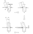
図7は本発明の第3実施例における探索動作を示す図である。図7(a)は傾けたワークが穴203周辺の凹凸部204の外縁に当接した状態を示し、図7(b)はワークが凹凸部204を乗り越えて挿入位置周辺の凹部に到達した状態を示し、図7(c)はワークが一部穴203へ落ち込んだ状態を示し、図7(d)はワークの傾きを予め設定された傾き量だけ戻して、ワークを垂直にした状態を示している。
なお、図7(c)において、401は図7(b)の状態からのワークの垂直方向の落ち込み量を示す。
本実施例では、第1実施例で説明した探索処理に加え、ワークが垂直方向に落ち込んだ際に、穴に到達したのか否かを判断し、穴に到達した場合にワークの傾きを予め設定された傾き量だけ戻す処理を行う。
FIG. 7 is a diagram showing a search operation in the third embodiment of the present invention. FIG. 7A shows a state in which the tilted workpiece is in contact with the outer edge of the
In FIG. 7C, 401 indicates the amount of vertical drop of the workpiece from the state of FIG. 7B.
In this embodiment, in addition to the search processing described in the first embodiment, it is determined whether or not the workpiece has reached the hole when the workpiece falls in the vertical direction, and the workpiece inclination is set in advance when the workpiece has reached the hole. A process for returning the tilt amount is performed.
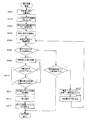
図8は本発明の第3実施例であるロボットの制御方法によって、対象物上の穴を探索してワークを挿入する処理手順を示すフローチャートである。
まず、ロボットはワーク201をグリッパ1003で把持し、ロボットの手先が外力に対して柔軟に動作するようにインピーダンス制御している状態で、予め教示された対象物上部に位置決めし(S301)、ワークを下げて対象物へ押し付ける(S302)。
次に、ワーク201を対象物へ押し付けたまま、予め設定された傾斜角(傾き量)だけワークを傾ける。このとき図4のように、探索進行方向側のワーク先端を持上げて傾ける(S303)。傾斜角(傾き量)は第1、第2実施例と同様、制御装置内に記憶されている値を参照する。
FIG. 8 is a flowchart showing a processing procedure for searching for a hole on an object and inserting a workpiece by the robot control method according to the third embodiment of the present invention.
First, the robot grips the
Next, the workpiece is tilted by a preset tilt angle (tilt amount) while the
次に、図3のように予め決められた探索領域205内の位置a1を始点、a2を終点とし(S304)、始点から終点の間を直線移動し(S305)、始点から終点までの間に力・モーメントセンサが探索進行方向からの反力を検出すれば、ワークが対象物上の穴付近へ到達して凹凸部204に当たったと判断し(S306)、ワークが対象物上の凹凸部に当たらずに終点a2まで到達した場合には、始点a1を図3のワーク座標系1012のX軸方向にΔXだけ移動した位置を終点b2とし、現在位置a2を同じくX軸方向にΔXだけ移動した位置を始点b1として(S307)、探索進行方向を反転させ、さらに探索進行方向を反転したので垂直軸に対する傾斜角(傾き量)の符号も反転して、探索進行方向に対してワーク先端を持上げるように傾ける(S308)。
S306にて探索進行方向からの反力を検出し穴付近へ到達したと判断するか、あるいは、予め決められた探索領域すべての探索が終わるまで、S305からS308までを繰り返す。
Next, as shown in FIG. 3, the position a1 in the
In S306, the reaction force from the direction of search is detected and it is determined that the vicinity of the hole has been reached, or S305 to S308 are repeated until the search of all the predetermined search areas is completed.
探索中に図7(a)の状態となり、S306で穴付近へ到達したと判断した場合には、そのまま探索進行方向にワークを移動させる(S309)。インピーダンス制御により、ロボットの手先は外力に対して柔軟に動作するのでワークは穴の縁の凹凸部204に乗り上げながら探索進行方向に進む。
この際にロボットの手先位置を制御周期ごとに取得し、その最も高い位置を制御装置内のメモリに一時的に記憶する。探索を継続しながら、最も高い位置と現在のロボットの手先位置との高さの差すなわちワークの高さの変化を求めながら、ワークが所定の落ち込み量閾値以上に垂直方向に落ち込んだか否か監視する。ここで落ち込み量閾値は制御装置内に予め記憶されており、探索動作中のワークの小さな上下動を穴に入ったと誤検出するのを避けるため、落ち込み量閾値は穴の縁の凸部の高さh1(304)以上に設定される。ここでは落ち込み量閾値をh1と同じ値に設定したとする。
ワーク201は対象物へ押し付けられているので、ワークの端が凹部へ入るとワークの垂直方向の位置が下がって一時的に図7(b)の実線のような状態になるが、この時点ではワークの垂直方向の位置の変化が穴の縁の凸部の高さh1(304)よりも小さいので、穴へ到達したとは判断せずに探索進行方向への移動を続ける。
移動を続けて図7(c)の実線のような状態になると、ワークの垂直方向の落ち込み量(401)が閾値である穴の縁の凸部の高さh1(304)よりも大きくなり、穴へ到達したと判断(S310)する。次に、S303で傾けたワークの傾斜角(傾き量)を図7(d)のように元に戻して、ワークを垂直にする(S311)。次に、穴の底までワークを挿入し(S312)、最後にグリッパを開いてワークを離し動作を終了する(S313)。
If the state shown in FIG. 7A is reached during the search and it is determined that the vicinity of the hole has been reached in S306, the workpiece is moved in the search advancing direction as it is (S309). By controlling the impedance, the hand of the robot moves flexibly with respect to an external force, so that the work advances in the direction of search while riding on the
At this time, the hand position of the robot is acquired for each control cycle, and the highest position is temporarily stored in the memory in the control device. While continuing the search, monitoring whether the workpiece has fallen vertically more than a predetermined drop amount threshold while obtaining the difference in height between the highest position and the current robot hand position, that is, the change in the workpiece height To do. Here, the drop amount threshold value is stored in the control device in advance, and in order to avoid erroneously detecting that a small vertical movement of the workpiece during the search operation has entered the hole, the drop amount threshold value is a height of the convex portion of the hole edge. It is set to h1 (304) or more. Here, it is assumed that the sagging amount threshold is set to the same value as h1.
Since the
When the movement is continued and a state as shown by a solid line in FIG. 7C is obtained, the vertical drop amount (401) of the workpiece becomes larger than the height h1 (304) of the convex portion of the hole edge, which is a threshold value. It is determined that the hole has been reached (S310). Next, the tilt angle (tilt amount) of the workpiece tilted in S303 is returned to the original position as shown in FIG. 7D to make the workpiece vertical (S311). Next, the work is inserted to the bottom of the hole (S312), and finally the gripper is opened to release the work and the operation is finished (S313).
このように、穴周辺の凹部にワークの端が入ったことを検知してからも探索動作を継続し、その後ワークが穴に到達したことを確認してワークを垂直に戻すので、挿入位置ではない凹みに対して無理にワークを挿入しようとして噛み付きを起こすことがないので、対象物の穴203の周囲に凹凸がある場合もワークは穴203へ到達することができ、穴へ挿入することができるのである。
In this way, the search operation is continued even after detecting that the end of the workpiece has entered the recess around the hole, and then the workpiece is returned to the vertical after confirming that the workpiece has reached the hole. Since there is no bite when trying to insert a workpiece into a dent that is not forced, the workpiece can reach the
図9は制御装置に接続された操作盤1108を使ってワーク落ち込み量閾値を制御装置に記憶する様子を表した図である。
図9の901は操作盤画面の挿入位置探索動作パラメータ入力画面であり、902は操作盤画面のワーク落ち込み量閾値の入力領域、903は設定ボタン、804は数値キーである。
落ち込み量閾値を記憶させる際には、まず図9に示すように、操作盤の画面上で落ち込み量閾値を入力する領域と設定ボタンを呼び出す。操作者が操作盤1108の数値キーで落ち込み量閾値の数値を入力し、設定ボタンを押すと、制御装置内の不揮発性のメモリに落ち込み量閾値が書き込まれる。メモリ内の落ち込み量は再度操作盤1108から数値を入力することによって書き換えることができる。そして探索動作の際にはメモリ上に書かれた落ち込み量閾値を参照して実行する。
このように、操作盤からワークの落ち込み量閾値を数値入力して設定するため、ロボットの操作者は、ロボットの実際の探索動作を確認して落ち込み量閾値を簡単に調整することができる。
FIG. 9 is a diagram illustrating a state in which the workpiece drop amount threshold value is stored in the control device using the operation panel 1108 connected to the control device.
901 in FIG. 9 is an operation panel screen insertion position search operation parameter input screen, 902 is a work drop amount threshold input area of the operation panel screen, 903 is a setting button, and 804 is a numerical key.
When storing the drop amount threshold, first, as shown in FIG. 9, an area for inputting the drop amount threshold and a setting button are called on the screen of the operation panel. When the operator inputs a numerical value of the drop amount threshold value using the numerical keys on the operation panel 1108 and presses the setting button, the drop amount threshold value is written in the non-volatile memory in the control device. The amount of drop in the memory can be rewritten by inputting a numerical value from the operation panel 1108 again. The search operation is executed with reference to the drop amount threshold value written in the memory.
Thus, since the workpiece drop amount threshold value is input and set from the operation panel, the robot operator can easily adjust the drop amount threshold value by confirming the actual search operation of the robot.
図10はコネクタ挿入の例である。601はワーク、602は対象物、603は挿入する穴である。穴603の縁に加え、ワーク601の外周部にも凹凸がある。
図11は図6のワークと対象物に本実施例を実行した場合の探索動作を示す図である。
図11(b)では、コネクタが嵌合できる状態ではないところで落ち込みが起こっており、この落ち込み量604をa1とする。図11(c)では、コネクタが嵌合できる位置で落ち込みが起こっており、この落ち込み量605をa2とする。ワーク落ち込み量閾値を前記a1とa2の間の値に設定しておけば、設定した値以上の落ち込みによってコネクタが嵌合できる位置であることを判断できる。
図11(c)において、ワークは傾いているが対象物とワークの凹凸が嵌まっており、このまま垂直方向にワークを対象物へ強い力で押し付けると噛み付いて動けなくなることがあるが、ワーク落ち込み量閾値を前記a1とa2の間の値に設定すれば、実施例3と同様に垂直方向に落ち込み量を監視し、落ち込み量a2が検出されることによってコネクタが嵌合できる位置に到達したと判断できる。その後図11(d)のようにワークの傾きを元に戻してワークを垂直にする動作を行うので、噛み付きを回避し、探索を継続して図11(e)のように挿入することができるのである。
なお、a1やa2は穴603の縁の凹凸やワーク外周部の凹凸の形状やワークの傾斜角から求めたり、実際に探索動作を行ったりして適切な値を決めそれをもとにワーク落ち込み量閾値を同定する。
FIG. 10 shows an example of connector insertion.
FIG. 11 is a diagram showing a search operation when the present embodiment is executed on the workpiece and the object shown in FIG.
In FIG. 11B, a drop has occurred where the connector is not in a state where it can be fitted, and this
In FIG. 11 (c), the workpiece is tilted but the unevenness between the object and the workpiece is fitted, and if the workpiece is pressed against the object with a strong force in the vertical direction as it is, the workpiece may be caught and become unable to move. If the amount threshold is set to a value between the a1 and a2, the amount of depression in the vertical direction is monitored in the same manner as in the third embodiment, and when the amount of depression a2 is detected, a position where the connector can be fitted is reached. I can judge. Thereafter, as shown in FIG. 11 (d), the work is returned to its original position to make the work vertical, so that the biting can be avoided and the search can be continued and inserted as shown in FIG. 11 (e). It is.
In addition, a1 and a2 are obtained from the unevenness of the edge of the
201 ワーク
202 対象物
203 穴(挿入位置)
204 穴の縁の凸部
205 探索領域
301 ワーク中心軸
302 ワーク直径
303 穴の中心軸
304 穴の縁の凸部の高さ
305 ワークの傾き量
306 ワークの傾き量
307 ワーク先端の対象物表面からの高さ
401 ワークの垂直方向の落ち込み量
601 ワーク
602 対象物
603 穴
604 ワーク落ち込み量a1
605 ワーク落ち込み量a2
801 挿入位置探索動作パラメータ入力画面
802 ワーク傾き量の入力領域
803 設定ボタン
804 数値キー
901 挿入位置探索動作パラメータ入力画面
902 ワーク落ち込み量の入力領域
903 設定ボタン
1001 ロボットの制御装置
1002 ロボット
1003 グリッパ
1004 力・モーメントセンサ
1005 ロボットと制御装置を接続するケーブル
1006 センサと制御装置を接続するケーブル
1007 テーブル
1011 ロボット座標系
1012 ワーク座標系
1013 ツール座標系
1101 メインコントロール部
1102 CPU
1103 メモリ
1104 バスブリッジ
1105 サーボ制御部
1106 I/O部
1107 操作盤インターフェース部
1108 操作盤
1109 モータ
1201 ワーク
1202 穴
1203 グリッパ
1204 傾斜角θ
1205 移動方向
1301 ワーク
1302 穴
1303 接触点C
1401 対象物
1402 微小角度a
201
204 Convex part of
605 Work drop amount a2
801 Insertion position search operation
1103
1205
1401 Object 1402 Minute angle a
Claims (8)
前記挿入位置を探索する際に、探索進行方向のワーク端を持上げ、前記ワークを前記対象物に対して予め設定された傾斜角で傾斜させることを特徴とする組み立て作業ロボットの制御方法。 A method for controlling an assembly robot that moves on the object in a state in which the work gripped by the robot is pressed against the object, searches for an insertion position provided on the object, and inserts the work into the insertion position. In
A method for controlling an assembly work robot, wherein when searching for the insertion position, a workpiece end in a search advancing direction is lifted and the workpiece is inclined with respect to the object at a preset inclination angle.
Priority Applications (1)
| Application Number | Priority Date | Filing Date | Title |
|---|---|---|---|
| JP2008313199A JP5071362B2 (en) | 2008-12-09 | 2008-12-09 | Assembly robot control method and assembly robot |
Applications Claiming Priority (1)
| Application Number | Priority Date | Filing Date | Title |
|---|---|---|---|
| JP2008313199A JP5071362B2 (en) | 2008-12-09 | 2008-12-09 | Assembly robot control method and assembly robot |
Publications (3)
| Publication Number | Publication Date |
|---|---|
| JP2010137299A JP2010137299A (en) | 2010-06-24 |
| JP2010137299A5 JP2010137299A5 (en) | 2011-07-14 |
| JP5071362B2 true JP5071362B2 (en) | 2012-11-14 |
Family
ID=42347878
Family Applications (1)
| Application Number | Title | Priority Date | Filing Date |
|---|---|---|---|
| JP2008313199A Active JP5071362B2 (en) | 2008-12-09 | 2008-12-09 | Assembly robot control method and assembly robot |
Country Status (1)
| Country | Link |
|---|---|
| JP (1) | JP5071362B2 (en) |
Families Citing this family (12)
| Publication number | Priority date | Publication date | Assignee | Title |
|---|---|---|---|---|
| JP5547559B2 (en) | 2010-06-16 | 2014-07-16 | 日立オートモティブシステムズ株式会社 | Power converter |
| JP6511715B2 (en) | 2013-10-31 | 2019-05-15 | セイコーエプソン株式会社 | Robot control device, robot system, and robot |
| JP6088563B2 (en) * | 2015-02-10 | 2017-03-01 | ファナック株式会社 | Work picking robot system having position and orientation conversion operation function, and work picking method |
| JP6046218B1 (en) * | 2015-07-09 | 2016-12-14 | ファナック株式会社 | Robot controller for a robot that puts objects together |
| JP6208724B2 (en) * | 2015-09-09 | 2017-10-04 | ファナック株式会社 | Object posture calculation system |
| JP6647184B2 (en) * | 2016-10-14 | 2020-02-14 | 株式会社馬場鐵工所 | Unnecessary part removing device and unnecessary part removing method |
| CN106514545B (en) * | 2016-10-26 | 2019-02-22 | 奇瑞汽车股份有限公司 | A kind of inclined hole press-loading apparatus |
| JP2020196076A (en) * | 2019-05-31 | 2020-12-10 | 三菱電機株式会社 | Robot controller and assembling method |
| US11833666B2 (en) | 2020-10-28 | 2023-12-05 | Shanghai Flexiv Robotics Technology Co., Ltd. | Method for assembling an operating member and an adapting member by a robot, robot, and controller |
| JP2022073012A (en) * | 2020-10-30 | 2022-05-17 | セイコーエプソン株式会社 | Robot control method and robot system |
| KR102561625B1 (en) * | 2021-07-30 | 2023-07-31 | 한국생산기술연구원 | An object assembly method using a robot |
| CN114147724B (en) * | 2021-12-20 | 2024-04-16 | 上海景吾智能科技有限公司 | Robot power control shaft hole assembly method and system |
Family Cites Families (5)
| Publication number | Priority date | Publication date | Assignee | Title |
|---|---|---|---|---|
| JPS63207530A (en) * | 1987-02-20 | 1988-08-26 | Res Dev Corp Of Japan | Precision automatic assembly device |
| JPH05108108A (en) * | 1991-05-10 | 1993-04-30 | Nok Corp | Compliance control method and controller |
| JP3580562B2 (en) * | 1992-10-28 | 2004-10-27 | 株式会社東芝 | robot |
| JPH07314262A (en) * | 1994-05-30 | 1995-12-05 | Ishikawajima Harima Heavy Ind Co Ltd | Pin insertion and device therefor |
| JP3961408B2 (en) * | 2002-11-21 | 2007-08-22 | ファナック株式会社 | Assembly method and apparatus |
-
2008
- 2008-12-09 JP JP2008313199A patent/JP5071362B2/en active Active
Also Published As
| Publication number | Publication date |
|---|---|
| JP2010137299A (en) | 2010-06-24 |
Similar Documents
| Publication | Publication Date | Title |
|---|---|---|
| JP5071362B2 (en) | Assembly robot control method and assembly robot | |
| JP4199264B2 (en) | Work picking apparatus and method | |
| US9868215B2 (en) | Object pick-up system and method for picking up stacked objects | |
| JP6055014B2 (en) | Robot control device having function of detecting contact with object or person | |
| US10059005B2 (en) | Method for teaching a robotic arm to pick or place an object | |
| US20090084766A1 (en) | Laser cutting system and method | |
| JP2019126894A (en) | Robot control device and robot system | |
| JPH03228591A (en) | Work holding device, work and storing case thereof | |
| JP2010137299A5 (en) | ||
| JP6208701B2 (en) | Robot system for adjusting position of coolant nozzle and robot control method | |
| WO2020052624A1 (en) | Metallurgical technology probe insertion calibration method employing visual measurement and insertion system thereof | |
| JP2010076054A (en) | Robot apparatus and control method of robot apparatus | |
| KR20210110191A (en) | Apparatus and method for controlling robot | |
| JP5024689B2 (en) | Assembly robot and its control method | |
| JP5218540B2 (en) | Assembly robot and its control method | |
| KR20190018665A (en) | Wire electrical discharge machine and wire electrical discharge machining method | |
| JP5088187B2 (en) | Robot installation method and robot production system | |
| KR102137615B1 (en) | Robot gripper for inspection and control method thereof | |
| EP3539729B1 (en) | Control device of robot and control method of robot | |
| JP2009125879A (en) | Robot system for assembling | |
| JPH04256526A (en) | Position detecting method for assembly parts | |
| JP4096305B2 (en) | Method and apparatus for automatic assembly of parts by robot | |
| JP6382918B2 (en) | Molding system having molding machine and molded product take-out device | |
| CN116940451A (en) | Robot system and workpiece supply method | |
| JP4549150B2 (en) | Interference area setting method for machine tools |
Legal Events
| Date | Code | Title | Description |
|---|---|---|---|
| A521 | Written amendment |
Free format text: JAPANESE INTERMEDIATE CODE: A523 Effective date: 20110531 |
|
| A621 | Written request for application examination |
Free format text: JAPANESE INTERMEDIATE CODE: A621 Effective date: 20110531 |
|
| RD02 | Notification of acceptance of power of attorney |
Free format text: JAPANESE INTERMEDIATE CODE: A7422 Effective date: 20120216 |
|
| TRDD | Decision of grant or rejection written | ||
| A977 | Report on retrieval |
Free format text: JAPANESE INTERMEDIATE CODE: A971007 Effective date: 20120718 |
|
| A01 | Written decision to grant a patent or to grant a registration (utility model) |
Free format text: JAPANESE INTERMEDIATE CODE: A01 Effective date: 20120724 |
|
| A01 | Written decision to grant a patent or to grant a registration (utility model) |
Free format text: JAPANESE INTERMEDIATE CODE: A01 |
|
| A61 | First payment of annual fees (during grant procedure) |
Free format text: JAPANESE INTERMEDIATE CODE: A61 Effective date: 20120806 |
|
| R150 | Certificate of patent or registration of utility model |
Ref document number: 5071362 Country of ref document: JP Free format text: JAPANESE INTERMEDIATE CODE: R150 Free format text: JAPANESE INTERMEDIATE CODE: R150 |
|
| FPAY | Renewal fee payment (event date is renewal date of database) |
Free format text: PAYMENT UNTIL: 20150831 Year of fee payment: 3 |