JP5067006B2 - Atmospheric pressure plasma treatment method - Google Patents
Atmospheric pressure plasma treatment method Download PDFInfo
- Publication number
- JP5067006B2 JP5067006B2 JP2007128786A JP2007128786A JP5067006B2 JP 5067006 B2 JP5067006 B2 JP 5067006B2 JP 2007128786 A JP2007128786 A JP 2007128786A JP 2007128786 A JP2007128786 A JP 2007128786A JP 5067006 B2 JP5067006 B2 JP 5067006B2
- Authority
- JP
- Japan
- Prior art keywords
- plasma
- outlet
- gas
- atmospheric pressure
- mixed gas
- Prior art date
- Legal status (The legal status is an assumption and is not a legal conclusion. Google has not performed a legal analysis and makes no representation as to the accuracy of the status listed.)
- Active
Links
Images


Landscapes
- Plasma Technology (AREA)
- Drying Of Semiconductors (AREA)
Description
本発明は、大気圧近傍でプラズマを発生させ、そのプラズマを被処理物の表面に吹き付けて被処理物を処理する大気圧プラズマ処理方法に関するものである。 The present invention generates a plasma in near atmospheric pressure, it relates to the plasma in the atmospheric pressure plasma treatment how to process an object to be processed is sprayed on the surface of the workpiece.
大気圧プラズマ発生装置は、所定の空間に不活性ガスやそれと反応性ガスとの混合ガスなどのガスを流しながらその空間に高周波電界を印加して放電を生じさせることで、大気圧近傍でプラズマを発生させるようにしたものであり、こうして発生させたプラズマを被処理物の表面に吹き付けて、被処理物の表面のクリーニング、レジストの除去、表面改質、金属酸化物の還元、製膜等の処理をすることは知られている。 An atmospheric pressure plasma generator generates plasma by applying a high-frequency electric field to a space while flowing a gas such as an inert gas or a mixture of a reactive gas and a reactive gas in a predetermined space. The plasma generated in this way is sprayed on the surface of the object to be processed, and the surface of the object to be processed is cleaned, the resist is removed, the surface is modified, the metal oxide is reduced, the film is formed, etc. It is known to process
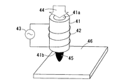
例えば、図11に示すように、誘電体から成る反応管41の外周にコイル42を巻回して配設し、コイル42に高周波電源43から高周波電圧を印加し、反応管41の一端41aからガス44を供給することで反応管41内でプラズマを発生させ、反応管41の他端41bの吹き出し口からプラズマ45を吹き出し、そのプラズマ45を被処理物46の表面に照射して上記のような各種処理を行うことは知られている。
For example, as shown in FIG. 11, a
また、図12に示すように、所定の空間51を挟んでその両側に誘電体52を介して一対の電極53a、53bを配設し、電極53a、53b間に高周波電源54から高周波電圧を印加し、空間51の一端51aからガス55を供給することで空間51の他端51bの吹き出し口からプラズマ56を吹き出し、そのプラズマ56を被処理物57の表面に照射して上記のような各種処理を行うことは知られている。
As shown in FIG. 12, a pair of
また、反応管にガスを導入するとともに内側電極と外側電極の間に交流電界を印加することで大気圧下で反応管内にグロー放電を発生させ、反応管からプラズマジェットを吹き出すプラズマ発生装置と、プラズマジェットの吹き出し位置に被処理物を搬送する搬送装置とを備えたブラズマ処理装置が知られている(例えば、特許文献1参照)。なお、この特許文献1においては、ガスの供給を停止してプラズマ処理を行っていない時に、反応管の吹き出し口を蓋体にて閉鎖する流入防止手段を設け、外部の空気が反応管内に流入するのを防止したり、他の方法として、プラズマを消灯する場合は、ガス供給を停止し、反応管に乾燥空気を供給して吹き出し口から出すようにすることが記載されている。
A plasma generator for introducing a gas into the reaction tube and applying an alternating electric field between the inner electrode and the outer electrode to generate a glow discharge in the reaction tube at atmospheric pressure and blowing a plasma jet from the reaction tube; 2. Description of the Related Art A plasma processing apparatus is known that includes a transport device that transports an object to be processed to a blowing position of a plasma jet (see, for example, Patent Document 1). In
また、プラズマ処理方法として、ガス供給路内に放電を生じさせてプラズマを発生させ、処理容器内でそのプラズマに被処理物を暴露させて処理を行い、処理容器から処理後のガスを回収し、回収したガスから不純物を除去して再生し、再生したガスをガス供給路内に返送するようにしたものも知られている(例えば、特許文献2参照)。 In addition, as a plasma processing method, discharge is generated in the gas supply path to generate plasma, the processing object is exposed to the plasma in the processing container, the processing is performed, and the processed gas is recovered from the processing container. Further, there is also known a technique in which impurities are removed from the recovered gas and regenerated, and the regenerated gas is returned to the gas supply path (see, for example, Patent Document 2).
なお、プラズマ発生部のその他の構成としては、断面形状が円形や細長い長方形状の誘電体から成る反応管の外周に管軸方向に間隔をあけて一対の電極を配設し、両電極間に高周波電圧を印加しつつ反応管にガスを供給することで反応管内でプラズマを発生するようにしたものや、誘電体から成る反応管の内側に内側電極を、外周に外側電極を配設し、両電極間に高周波電圧を印加しつつ反応管内にガスを供給することで反応管内でプラズマを発生するようにしたものや、所定の空間を挟んでその上下に誘電体を介して一対の電極を配設し、両電極間に高周波電圧を印加しつつ空間内にガスを供給することで空間内にプラズマを発生するようにしたものなども知られている。
ところで、従来の大気圧プラズマ処理方法においては、ガス消費量が数l/分〜数百l/分程度必要であり、真空圧プラズマ処理装置の場合の数百ml/分程度のガス消費量に比して格段に大きくなっており、かつ大気圧プラズマに使用するガスは純度が低いとプラズマが不安定になるためコストの高い高純度のものが必要であるため、プラズマ処理のランニングコストが高くなるという問題があった。 By the way, in the conventional atmospheric pressure plasma processing method, the gas consumption needs to be several l / min to several hundred l / min, and the gas consumption is about several hundred ml / min in the case of the vacuum pressure plasma processing apparatus. The gas used for atmospheric pressure plasma is much larger than that, and if the purity is low, the plasma becomes unstable. There was a problem of becoming.
この問題に対して、プラズマを発生する反応空間へのガス供給量を、反応空間でプラズマを発生させるのに必要なガス供給量の下限を極限としてその近傍まで低減することが考えられるが、その場合には反応空間から吹き出したプラズマを被処理物表面に照射しても殆どプラズマ処理することができない。これは、大気中では大気圧プラズマの寿命が短く、プラズマが被処理物表面に到達するまでに消滅してしまうためである。従来は、ガス供給量を多量に設定することで、プラズマガスの吹き出し流速を高め、大部分のプラズマが大気と接触しない内に被処理物表面に到達するとともに被処理物表面に到達するまでの時間がプラズマの寿命範囲に収まるようにしていたのであり、その結果上記のような問題を生じていたのである。 To solve this problem, it is conceivable to reduce the gas supply amount to the reaction space that generates plasma to the vicinity thereof with the lower limit of the gas supply amount necessary to generate plasma in the reaction space as the limit. In some cases, even if the surface of the object to be processed is irradiated with plasma blown out from the reaction space, the plasma processing can hardly be performed. This is because the atmospheric pressure plasma has a short lifetime in the atmosphere and disappears before the plasma reaches the surface of the workpiece. Conventionally, by setting a large amount of gas supply, the flow velocity of the plasma gas is increased, so that most of the plasma does not come into contact with the atmosphere before reaching the surface of the workpiece and reaching the surface of the workpiece. The time was kept within the lifetime of the plasma, and as a result, the above-described problems were caused.
また、従来はガス供給量を多くしているので、プラズマガスの吹き出し流速が高くなり、被処理物表面に微小な部品が配置されている場合に、吹き飛ばしたり、移動させてしまう恐れがあるという問題もあった。 In addition, since the gas supply amount has been increased in the past, the plasma gas blowing flow rate becomes high, and there is a risk of blowing off or moving when minute parts are arranged on the surface of the object to be processed. There was also a problem.
また、特許文献1には、このような問題及び解決手段について記載も示唆もなされていず、特許文献2でも、ガス消費量を低減するという課題はあるが、解決手段の構成が大掛かりで極めてコスト高なるとともに、処理工程も複雑になって処理効率が悪く、大気圧プズマによる処理の利点を十分に生かせないという問題がある。
本発明は、上記従来の問題点に鑑み、大気圧プラズマにて被処理物を処理するに際してガス供給量の低減を図りつつ、大きな面積のプラズマ処理を確実にかつ安定して行うことができる大気圧プラズマ処理方法を提供することを目的とする。 In view of the above-mentioned conventional problems, the present invention is capable of reliably and stably performing a large area of plasma processing while reducing the gas supply amount when processing an object to be processed with atmospheric pressure plasma. and to provide a pressure plasma treatment how.
本発明の大気圧プラズマ処理方法は、大気圧近傍で発生させたプラズマを吹き出し口から被処理物表面に向けて吹き出し、前記被処理物表面を処理する大気圧プラズマ処理方法において、前記吹き出し口の開口周長と、前記吹き出し口と前記被処理物表面の間の隙間の積で与えられる前記吹き出し口と被処理物との間の開口面積Bが、前記吹き出し口の開口断面積Aに対して、B≦Aとなるように、前記吹き出し口と前記被処理物の間の隙間を設定して処理を行うものであり、反応容器の内部に形成される反応空間に第1の不活性ガスを供給しつつ前記反応空間に高周波電界を印加して一次プラズマを発生させ、発生した一次プラズマを、前記反応容器の下端出口の周囲に配設された混合ガス容器の内部に形成され、第2の不活性ガスを主とし適量の反応性ガスを含む混合ガスが前記混合ガス容器の上部外周に配設されたガス供給口より供給される混合ガス領域に吹き出させてプラズマ化した混合ガスからなる二次プラズマを発生させ、発生した二次プラズマを前記混合ガス容器の下端開口にて構成される前記吹き出し口から吹き出し、一端が前記下端出口として開口した前記反応容器の他端の上端開口から第1の不活性ガスを供給しつつ前記反応空間に高周波電界を印加し、前記反応空間内で一次プラズマを発生させて前記下端出口から吹き出すものである。 Atmospheric pressure plasma treatment method of the present invention, balloon toward the object surface to be treated from the inlet blown plasma generated at atmospheric pressure near the atmospheric pressure plasma processing method for processing the object surface to be treated, the outlet an opening perimeter, the opening area B between the given by the product of the gap the outlet and the object to be treated between the outlet and the object to be processed surface, the opening cross-sectional area a of the outlet , so that the B ≦ a, der which set the gap performs processing between the outlet and the object to be processed is, first inert gas into the reaction space formed inside the reaction vessel A high frequency electric field is applied to the reaction space to generate primary plasma, and the generated primary plasma is formed inside a mixed gas container disposed around a lower end outlet of the reaction container, Mainly with inert gas A mixed gas containing an appropriate amount of reactive gas is blown into a mixed gas region supplied from a gas supply port disposed on the upper outer periphery of the mixed gas container to generate a secondary plasma composed of a mixed gas that has been converted into plasma, The generated secondary plasma is blown out from the blowout opening constituted by the lower end opening of the mixed gas container, and the first inert gas is supplied from the upper end opening at the other end of the reaction container opened at one end as the lower end outlet. the high-frequency electric field is applied to the reaction space, Ru der which the by generating a primary plasma in the reaction space blown from the lower outlet while.
この構成によると、吹き出し口と被処理物の間の隙間を、上記のように吹き出し口と被処理物との間の開口面積Bが吹き出し口の開口断面積Aより小さくなるように調整設定することで、吹き出し口から吹き出したプラズマは、吹き出し口の口縁と被処理物との間の隙間の内側に完全に満たされ、その外側で大気に接触することになり、吹き出したプラズマが被処理物表面に到達するまでに消滅する要因を殆ど無くすことができるので、プラズマを発生して吹き出し口から吹き出すことができる最小限近傍のガス供給量でプラズマを発生させても、少なくとも被処理物における吹き出し口の開口断面積に対応する領域を確実にプラズマ処理することができ、ガス供給量の低減を図りつつ、大きな面積のプラズマ処理を確実にかつ安定して行うことができる。プラズマを発生して吹き出させることができるガス供給量は、ガスの種類や混合ガスの場合はその組成比、印加する高周波電圧の周波数帯や電圧値などによって規定されるものである。
また、反応容器の内部に形成される反応空間に第1の不活性ガスを供給しつつ反応空間に高周波電界を印加して一次プラズマを発生させ、発生した一次プラズマを、反応容器の下端出口の周囲に配設された混合ガス容器の内部に形成され、第2の不活性ガスを主とし適量の反応性ガスを含む混合ガスが混合ガス容器の上部外周に配設されたガス供給口より供給される混合ガス領域に吹き出させてプラズマ化した混合ガスからなる二次プラズマを発生させ、発生した二次プラズマを混合ガス容器の下端開口にて構成される吹き出し口から吹き出すようにすると、第1の不活性ガスとして高純度の不活性ガスを用いて小さい一次プラズマを発生させ、混合ガス領域に吹き出すことで、混合ガス領域で雪崩現象的にプラズマが展開して多量の二次プラズマを発生させることができ、高価な高純度の第1の不活性ガスのガス供給量をさらに低減できるとともに、安価なガスを用いることができる混合ガスのガス供給量に応じてプラズマの吹き出し口を大きくすることができ、処理領域を大きくしながらランニングコストの一層の低廉化を図ることができる。
According to this configuration, the gap between the outlet and the object to be processed is adjusted and set so that the opening area B between the outlet and the object to be processed becomes smaller than the opening cross-sectional area A of the outlet as described above. Thus, the plasma blown out from the blowout port is completely filled inside the gap between the lip of the blowout port and the object to be processed, and comes into contact with the atmosphere on the outside. Since most of the factors that disappear before reaching the surface of the object can be eliminated, even if plasma is generated with a gas supply amount close to the minimum that can be generated and blown out from the outlet, at least in the object to be processed The region corresponding to the opening cross-sectional area of the outlet can be reliably subjected to plasma processing, and the plasma treatment of a large area is reliably and stably performed while reducing the gas supply amount. Door can be. The amount of gas that can be generated and blown out is determined by the type of gas, the composition ratio in the case of a mixed gas, the frequency band of the applied high-frequency voltage, the voltage value, and the like.
In addition, a primary plasma is generated by applying a high frequency electric field to the reaction space while supplying the first inert gas to the reaction space formed inside the reaction vessel, and the generated primary plasma is discharged from the lower end outlet of the reaction vessel. A gas mixture formed in the surroundings of the mixed gas container and mainly containing the second inert gas and containing an appropriate amount of reactive gas is supplied from a gas supply port provided on the upper outer periphery of the mixed gas container. When the secondary plasma made of the mixed gas blown into the mixed gas region to be generated is generated and the generated secondary plasma is blown out from the outlet formed by the lower end opening of the mixed gas container , the first A small primary plasma is generated using an inert gas of high purity as the inert gas of the gas and blown out to the mixed gas region. The amount of gas supply of the high-purity first inert gas can be further reduced, and the plasma outlet can be used in accordance with the gas supply amount of the mixed gas in which an inexpensive gas can be used. The running cost can be further reduced while increasing the processing area.
また、大気圧近傍でプラズマを発生させて吹き出し口から吹き出すのに、一端が吹き出し口として開口した反応空間の他端からガスを供給しつつ反応空間に高周波電界を印加し、反応空間内でプラズマを発生させて吹き出し口から吹き出すようにすると、簡単な構成にて安定してプラズマを吹き出すことができる。 In addition, in order to generate plasma near the atmospheric pressure and blow it out from the outlet, a high-frequency electric field is applied to the reaction space while supplying gas from the other end of the reaction space where one end is opened as the outlet, and plasma is generated in the reaction space. Is generated and blown out from the blowout port, plasma can be blown out stably with a simple configuration.
本発明の大気圧プラズマ処理方法によれば、吹き出し口と被処理物の間の隙間を、吹き出し口と被処理物との間の開口面積Bが吹き出し口の開口断面積Aより小さくなるように調整設定することで、吹き出し口からプラズマを吹き出すことができる最小限近傍のガス供給量でプラズマを発生させても、プラズマが吹き出し口の口縁と被処理物との間の隙間の内側に完全に満たされた状態とすることができ、被処理物における吹き出し口の開口断面積に対応する領域を確実にプラズマ処理することができ、したがってガス供給量の低減を図りつつ大きな面積のプラズマ処理ができ、効率的にかつ安定してプラズマ処理を行うことができる。 According to atmospheric pressure plasma treatment how the present invention, the gap between the outlet and the object to be treated, outlet and to be smaller than the opening cross-sectional area A the opening area B is outlet of between the object to be processed Even if the plasma is generated with a gas supply amount close to the minimum that can blow out the plasma from the blowout port, the plasma is inside the gap between the mouth of the blowout port and the workpiece. It is possible to achieve a completely filled state, and it is possible to reliably perform plasma processing on a region corresponding to the opening cross-sectional area of the blowout port in the object to be processed. Therefore, plasma processing of a large area while reducing the gas supply amount The plasma treatment can be performed efficiently and stably.
以下、本発明の大気圧プラズマ処理装置の各実施形態について、図1〜図10を参照して説明する。 Hereinafter, each embodiment of the atmospheric pressure plasma processing apparatus of the present invention will be described with reference to FIGS.
(第1の実施形態)
まず、本発明の大気圧プラズマ処理装置の第1の実施形態について、図1〜図3を参照して説明する。
(First embodiment)
First, a first embodiment of an atmospheric pressure plasma processing apparatus of the present invention will be described with reference to FIGS.
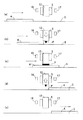
図1において、1は大気圧プラズマ処理装置であり、大気圧近傍でプラズマPを発生して吹き出し口3から吹き出すプラズマ発生部2と、被処理物4をプラズマ発生部2に対して相対移動させて被処理物4の表面にプラズマPを照射させる移動手段5とを備えている。移動手段5は、図示例のように被処理物4を移動させても、プラズマ発生部2を移動させても良い。また、詳細機構は図示していないが、移動手段5は、プラズマ発生部2の吹き出し口3と被処理物4の間の隙間Gも調整設定できるように構成されている。
In FIG. 1,
プラズマ発生部2は、一端に吹き出し口3を有し、内部に反応空間6aを形成する誘電体からなる筒状の反応容器6と、反応容器6の外周に巻回して配設されたコイル状のアンテナ7とを備えている。アンテナ7には高周波発生手段としての高周波電源8が接続され、アンテナ7に13.56MHzに代表されるRF周波数帯、又は100MHzに代表されるVHF周波数帯の電圧を印加するように構成されている。
The
反応容器6の他端開口6bには、ガス供給部9からマスフローコントローラなど、流量を直接高精度に制御できる流量制御手段10を介して所要の一定流量のガス11を供給するように構成されている。ガス供給部9から供給するガスは、アルゴン、ネオン、キセノン、ヘリウム、窒素から選択された単独ガス又は複数の混合ガスからなる不活性ガスを主とするもので、それによってプラズマを容易かつ安定して発生させることができ、かつプラズマ処理の種類に応じて、各種の反応性ガスを混合したガスを供給する。
The other end opening 6b of the
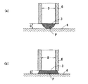
本実施形態では、移動手段5にてプラズマ発生部2と被処理物4を相対移動させてその表面をプラズマ処理する際に、プラズマ発生部2の吹き出し口3と被処理物4の表面との間の隙間Gを規制することで、被処理物4の表面における吹き出し口3に対向する範囲の領域を確実に安定してプラズマ処理するようにしている。すなわち、本発明者がプラズマ処理におけるガス11の供給量の低減を図りつつ確実にプラズマ処理するプラズマ処理条件を鋭意研究する中で、吹き出し口3からプラズマPを吹き出すのに必要な所要流量のガス11を供給してプラズマPを吹き出した状態で、吹き出し口3と被処理物4の間の隙間Gを、プラズマ処理を行う通常の範囲に設定した場合には、図2(a)に示すように、吹き出したプラズマPが被処理物4の表面に十分に到達せずに消滅し、プラズマ処理を確実に行うことができなかった。一方、吹き出し口3と被処理物4の間の隙間Gを小さくして行くと、プラズマガスの吹き出し抵抗が大きくなってガス流量が低下し、プラズマPが消灯してしまうことが判明した。そのため、従来は隙間Gを保ったままガス11の供給量を増加して所要の領域のプラズマ処理を行うようにしていたのである。これに対して、本発明者は流量制御手段10にて隙間Gが小さくなってもガスの供給量が維持されるようにしつつ、吹き出し口3と被処理物4の間の隙間Gを小さくして行くと、隙間Gが反応容器6の内径Dに対してある規定値以下になった時点で突如として一気に、図2(b)に示すように、吹き出し口3と被処理物4との間の隙間の全面にプラズマPが満たされた状態となり、少なくとも吹き出し口3に対向する範囲の領域の全面のプラズマ処理を確実に行えることを見出し、本発明を発明するに至ったのである。
In this embodiment, when the
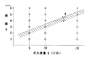
具体例を図3を参照して説明する。内径Dが10mmの反応容器6に、不活性ガスとしてのアルゴンガスが99%、反応性ガスとしての酸素ガスが1%の組成の混合ガスから成るガス11を、ガス流量Vが5l/分、10l/分、20l/分の一定流量に設定してそれぞれ供給し、各流量毎に隙間Gを、1mm〜6mmの範囲で1mm間隔で変化させて被処理物の表面改質処理を行い、表面改質処理が適切に行われたか否かの評価を行った。その結果を、図3に示している。図3において、○は表面改質が適切に行われた例、×は適切に行われなかった例を表示している。なお、表面改質処理が適切に行なわれたか否かの評価は、処理後の被処理物上に水等の液体を滴下し、その液体が形成する角度(一般に接触角と呼ぶ。)を測定し、行なった。接触角が所定値以上であれば、表面改質が行なわれておらず、所定値以下になっていれば、表面改質が行なわれたと判定している。また、この例では5l/分が反応容器6からプラズマPを吹き出させることができる最小限近傍のガス11の供給量であり、これ以下の流量では吹き出し口3から安定してプラズマPを吹き出すことはできなかった。
A specific example will be described with reference to FIG. In a
図3によれば、ガス流量Vが5l/分の時には、隙間Gが2mmでは処理が適切に行われ、3mmでは処理が適切に行われないので、その境界は2.5mmとなり、10l/分の時には、隙間Gが3mmでは処理が適切に行われ、4mmでは処理が適切に行われないので、その境界は3.5mmとなり、20l/分の時には、隙間Gが5mmでは処理が適切に行われ、6mmでは処理が適切に行われないので、その境界は5.5mmとなる。このことから、隙間Gを2.5mm以下とすることで、プラズマPを吹き出させることができる最少限近傍のガス供給量でも吹き出し口3に対向する範囲の領域で確実に適切にプラズマ処理できることが判明した。また、図3から、供給するガス流量Vを増加することにより、その増加倍数に所定の係数Kを掛けた割合で隙間Gを大きく設定しても、確実に適切にプラズマ処理できることが判明する。
According to FIG. 3, when the gas flow rate V is 5 l / min, processing is properly performed when the gap G is 2 mm, and processing is not performed properly at 3 mm, so the boundary is 2.5 mm and 10 l / min. When the gap G is 3 mm, the process is properly performed and when 4 mm is not performed, the boundary is 3.5 mm. When the gap is 20 l / min, the process is appropriately performed when the gap G is 5 mm. However, since the processing is not properly performed at 6 mm, the boundary is 5.5 mm. From this, by setting the gap G to 2.5 mm or less, it is possible to reliably and appropriately perform the plasma processing in the region in the range facing the blowing
他の具体例についても同様に検討して分析した結果、最小限近傍のガス供給量でも反応容器6の内径Dに対して隙間Gを次のように設定することによって、少なくとも吹き出し口3に対向する範囲の領域で確実に適切にプラズマ処理できることが判明した。すなわち、図1(a)、(b)に示すように、吹き出し口3の開口断面積をA、吹き出し口3の開口周長と隙間Gの積で与えられる吹き出し口3と被処理物4との間の開口面積をBとして、A≧Bとなるように隙間Gを設定することで、吹き出したプラズマPで隙間Gの全体が満たされた状態となるため、確実に適切なプラズマ処理できるものと考えられる。吹き出し口3が円孔である場合には、A=πD2 /4、B=πDGであるので、G≦D/4、すなわち吹き出し口3の半径の半分以下に設定することで適切なプラズマ処理を確保することができるのである。
As a result of examining and analyzing other specific examples in the same manner, the gap G is set to the inner diameter D of the
(第2の実施形態)
次に、本発明の大気圧プラズマ処理装置の第2の実施形態について、図4〜図8を参照して説明する。なお、以下の実施形態の説明では、先行する実施形態と同一の構成要素については同一の参照符号を付して説明を省略し、主として相違点について説明する。
(Second Embodiment)
Next, a second embodiment of the atmospheric pressure plasma processing apparatus of the present invention will be described with reference to FIGS. In the following description of the embodiment, the same components as those in the preceding embodiment are denoted by the same reference numerals, description thereof is omitted, and differences are mainly described.
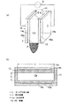
本実施形態の大気圧プラズマ処理装置1のプラズマ発生部12は、図4(a)、(b)に示すように、長辺がL1 、短辺がL2 の長方形の横断面形状の反応空間13aの少なくとも一方の対向面が、図示例では四周面が、誘電体から成る反応容器13を備え、その対向壁面の背面に一対の電極14a、14bとその外側の絶縁被覆板15a、15bとを配置した構成としている。そして、一対の電極14a、14bに対して高周波電源8から高周波電圧を印加し、反応空間13aの上方からガス11を供給することで、下端の吹き出し口3からプラズマPを吹き出すように構成されている。印加する高周波電圧としては、数KHz〜数100KHz、又は13.56MHzに代表されるRF周波数帯、又は100MHzに代表されるVHF周波数帯、さらに電子レンジに使用される2.45GHzに代表されるマイクロ波周波数帯などを適用できる。他の実施形態についても同じであるが、高周波電源と電極又はアンテナとの間に反射波を抑制するために整合回路(図示せず)を入れることが、一般的である。
As shown in FIGS. 4A and 4B, the
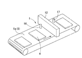
本実施形態のプラズマ発生部12は、図5に示すように、被処理物4を一定搬送経路上を移動させる移動手段5としての搬送コンベア5a上にその搬送経路上を横断するように配置されている。また、図示を省略しているが、移動手段5はプラズマ発生部12を搬送コンベア5aに対して昇降動作させてその高さ位置を調整設定できるように構成されている。また、搬送コンベア5aの搬送方向におけるプラズマ発生部12の上手側と下手側にそれぞれ処理開始認識手段16と処理終了認識手段17が配置されている。処理開始認識手段16と処理終了認識手段17は、搬送コンベア5aで搬送されてくる被処理物4を検出するセンサからなり、その検出信号の立ち上がりと立ち下がりにより被処理物4の始端と終端をそれぞれ認識するように構成されている。
As shown in FIG. 5, the
また、本実施形態の大気圧プラズマ処理装置1においては、図6に示すように、制御部18にて移動手段5と高周波電源8と流量制御手段10が動作制御されている。制御部18は、処理開始認識手段16と処理終了認識手段17から入力された信号に基づいて、被処理物4に対する処理開始と終了の決定を行い、被処理物4に対する処理時には、移動手段5を制御してプラズマ発生部12の高さ位置を調整設定するとともに、流量制御手段10を制御してプラズマ発生部12からプラズマPが吹き出すのに必要な最小限近傍のガス流量を供給し、被処理物4に対する処理を行わない間は、プラズマ発生部12を待機位置まで退避させるとともに、反応空間13a内でのプラズマの点灯状態を維持できる最少限程度にガス流量を減少させるように構成されている。
Further, in the atmospheric pressure
次に、図7を参照して被処理物4の処理過程を説明する。まず、被処理物4がプラズマ発生部12から離れて位置している状態では、図7(a)に示すように、処理開始認識手段16により被処理物2が検出されていない状態であるので、ガス流量が反応空間13a内でプラズマPが点灯しているだけの点灯状態を維持できる程度に絞られるとともに、プラズマ発生部12が待機位置に退避されている。次に、図7(b)に示すように、被処理物4の始端が処理開始認識手段16にて検出されると、制御部18にて流量制御手段10が制御され、ガス流量が吹き出し口3からプラズマPが吹き出すのに必要な最小限近傍の流量に制御されて吹き出し口3からプラズマPが吹き出し、プラズマ発生部12の高さ位置が所定高さ位置に設定される。その直後から、図7(c)に示すように、被処理物4に対するプラズマPによる処理が行われる。次に、図7(d)に示すように、被処理物4の終端が処理終了認識手段17にて検出されると、直後に、図7(e)に示すように、制御部18にて流量制御手段10が制御されてガス流量が上記のように点灯状態を維持できる程度に絞られるとともに、移動手段5が制御されてプラズマ発生部12が待機位置に退避される。以降、上記動作が繰り返される。
Next, the process of the
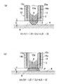
上記図7(c)に示したプラズマ処理に際して、図8(a)に示すように、吹き出し口3と被処理物4の間の隙間Gが、吹き出し口3の開口断面積A(=L1 ・L2 )より、吹き出し口3の開口周縁と被処理物4との間の隙間Gの開口面積B(=G・(L1 +L2 )・2)の方が大きい場合、すなわちG>(L1 ・L2 )/{((L1 +L2 )・2}の場合には、吹き出したプラズマPが被処理物4の表面に十分に到達せずに消滅し、プラズマ処理が確実に行われないが、図8(b)に示すように、開口断面積Aより隙間Gの開口面積Bの方が小さくなるように隙間Gを設定すること、すなわちG≦(L1 ・L2 )/{((L1 +L2 )・2}に設定することで、吹き出し口3と被処理物4との間の隙間の全面にプラズマPが満たされた状態となって、少なくとも吹き出し口3に対向する範囲の領域の全面のプラズマ処理を確実に行うことができる。
In the plasma processing shown in FIG. 7C, as shown in FIG. 8A, the gap G between the
本実施形態でも上記実施形態と同様の作用効果を奏することができるとともに、被処理物4に対する処理の開始と終了を決定し、開始から終了の間のみガス流量をプラズマPが吹き出し口3から吹き出す流量に制御し、それ以外の間はプラズマPの点灯状態が維持される程度に低減することにより、被処理物4に対するプラズマ処理を安定して処理を行いながらガスの使用量をさらに低減することができ、ランニングコストの低下を図りながら効率的にかつ安定してプラズマ処理を行うことができる。
In the present embodiment, the same operational effects as in the above-described embodiment can be obtained, and the start and end of the process on the
(第3の実施形態)
次に、本発明の大気圧プラズマ処理装置の第3の実施形態について、図9を参照して説明する。
(Third embodiment)
Next, a third embodiment of the atmospheric pressure plasma processing apparatus of the present invention will be described with reference to FIG.
上記第1、第2の実施形態では、プラズマ発生部2、12の構成として、一端が吹き出し口3として開口した反応空間6a、13aの他端からガス11を供給しつつ、アンテナ7又は電極14a、14bから反応空間6a、13a内に高周波電圧を印加し、反応空間6a、13a内で発生させたプラズマPを吹き出し口3から吹き出すようにした例を示したが、本実施形態のプラズマ発生部20では、プラズマPの発生効率を向上するため、第1の不活性ガスを用いて上記のようにして発生させた一次プラズマを、第2の不活性ガスを主とし適量の反応性ガスを含む混合ガスが供給される混合ガス領域に吹き出させることで、混合ガスを雪崩現象的にプラズマ化して二次プラズマを発生させ、その二次プラズマをプラズマPとして吹き出し口から吹き出すようにしている。
In the first and second embodiments, the
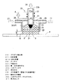
このプラズマ発生部20の具体的な構成を図9を参照して説明する。断面円形の反応空間21aを形成する誘電体からなる円筒状の反応容器21の周囲にコイル状のアンテナ22を配設し、アンテナ22に高周波電源8から高周波電圧を印加して反応空間21aに高周波電界を印加し、反応容器21の上端開口21bから第1の不活性ガス24を供給することで、反応容器21の下端出口23から一次プラズマ25を吹き出すように構成されている。反応容器21の下端出口23近傍の周囲には下端開放の混合ガス容器26が配設されている。混合ガス容器26の上部外周には複数のガス供給口28が配設され、内部に第2の不活性ガスを主とし適量の反応性ガスを含む混合ガス27を供給するように構成されている。また、混合ガス容器26は、反応容器21の下端より下方に延出され、反応容器21の下端より下方に、供給された混合ガス27で満たされた下端開放の混合ガス領域29を形成するように構成されている。この下端開放の混合ガス領域29に一次プラズマ25が衝突することで二次プラズマ30が発生し、発生した二次プラズマ30が、混合ガス容器26の下端開口にて構成される吹き出し口31からプラズマPとして吹き出すように構成されている。
A specific configuration of the
以上の構成において、反応容器21の下端開口23から一次プラズマ25を吹き出している状態で、混合ガス容器26内に混合ガス27を供給することで、混合ガス領域29内で混合ガス29に一次プラズマ25が衝突して二次プラズマ30が発生し、その二次プラズマ30が混合ガス領域29の全領域に展開してさらに吹き出し口31からプラズマPとして下方に吹き出す。このプラズマPを被処理物4に照射することで、所望のプラズマ処理が行われる。
In the above configuration, the primary plasma 25 is supplied to the mixed gas 29 in the mixed gas region 29 by supplying the
このプラズマ発生部20によれば、反応容器21の内径dを小さくして第1の不活性ガス24のガス供給量を少なくしても発生させた一次プラズマ25によって二次プラズマ30を大きく展開させることができるので、第1や第2の実施形態の場合に比して、混合ガス容器26の下端の吹き出し口31の開口面積を大きく設定することができ、かつ混合ガス領域29に供給する混合ガス27のガス供給量も吹き出し口31から二次プラズマ30が確実に吹き出す程度まで絞っても、上記実施形態と同様に吹き出し口31と被処理物4との間の隙間Gを、吹き出し口31の開口断面積をAとし、吹き出し口31と被処理物4との間の開口面積をBとして、B≦Aとなるように、吹き出し口31と被処理物4との間の隙間Gを調整設定してプラズマ処理を行うことにより、第1の不活性ガス24及び混合ガス27の供給量の低減を図りながら吹き出し口31の開口面積に対応する大きな領域のプラズマ処理を安定して確実に行うことができる。
According to the
(第4の実施形態)
次に、本発明の大気圧プラズマ処理装置の第4の実施形態について、図10を参照して説明する。
(Fourth embodiment)
Next, a fourth embodiment of the atmospheric pressure plasma processing apparatus of the present invention will be described with reference to FIG.
本実施形態のプラズマ発生部2では、図10に示すように、反応容器6の吹き出し口3の周縁から被処理物4の表面に平行に対向するように所要幅の対向壁面32を設けている。そして、制御部(図示せず)が、吹き出し口3及び対向壁面32と被処理物4の表面との間に設けるべき隙間Gに設定されるように移動手段5を制御するとともに、その隙間Gに応じて流量制御手段10を制御して吹き出し口3から吹き出すプラズマPのガス流量を調整するように構成されている。
In the
次に、上記カズ流量の調整方法について説明する。反応容器6の内径、すなわち反応空間6aの径をD1 、対向壁面32の外周径をD2 とすると、吹き出し口3の開口断面積Aは、πD1 2 /4で与えられ、対向壁面32と被処理物4との間の隙間Gの開口面積Bは、πD2 Gで与えられるため、A≧Bとするには、G≦D1 2 /4D2 となり、D1<<D2 であるため、Gは小さな値にならざるを得ない。ここで、吹き出し口3からプラズマPを吹き出すのに必要な最少限近傍のガス流量をV1 とし、供給するガス流量をV2 (V1 <V2 )に増加すると、設定できる隙間Gは、G≦(D1 2 /4D2 )・(V2 /V1 )・Kで与えられる。ここで、Kは、図3の勾配Kに対応する所定の係数であり、反応容器6の仕様、ガスの種類や組成、高周波電圧の周波数帯等の条件によって定まるもので、実験的に求められるものである。
Next, a method for adjusting the above-described gas flow rate will be described. The inner diameter of the
このように、吹き出し口3の周縁から被処理物4表面に平行に対向するように所要幅の対向壁面32を形成すると、対向壁面32の周縁と被処理物4表面との間の開口面積Bが大きくなり、それに対応して設定すべき隙間Gが小さくなるが、ガス供給量を、吹き出し口3からプラズマPを吹き出すのに必要な最少限近傍の流量V1 から流量V2 に増大させることで、V2 /V1 の比に係数Kを乗じた割合で隙間Gを大きく設定することができ、処理に必要な隙間Gを確保することができるのである。
Thus, when the opposing
本実施形態によれば、吹き出し口3及び対向壁面32と被処理物4の表面との間の隙間Gを確保しつつ、対向壁面32の大きさの面積のプラズマ処理を一度にかつ確実に安定して行うことができ、プラズマ処理の品質と効率の向上を図ることができる。
According to the present embodiment, the plasma processing of the area of the size of the opposing
本発明は、以上の実施形態に限らず、請求項の記載に基づいて各実施形態に示した種々の構成要素を組み合わせた構成で実施することができる。 The present invention is not limited to the above-described embodiment, and can be implemented with a combination of various components shown in each embodiment based on the description of the claims.
本発明の大気圧プラズマ処理方法によれば、吹き出し口と被処理物の間の隙間を、吹き出し口と被処理物との間の開口面積Bが吹き出し口の開口断面積Aより小さくなるように調整設定することで、吹き出し口からプラズマを吹き出すことができる最小限近傍のガス供給量でプラズマを発生させても、被処理物における吹き出し口の開口断面積に対応する領域を確実にプラズマ処理することができ、ガス供給量の低減を図りつつ大きな面積のプラズマ処理を行うことができるので大気圧プラズマ処理に有効に利用できる。 According to atmospheric pressure plasma treatment how the present invention, the gap between the outlet and the object to be treated, outlet and to be smaller than the opening cross-sectional area A the opening area B is outlet of between the object to be processed Even if plasma is generated with a gas supply amount close to the minimum that allows plasma to be blown out from the blowout port, the region corresponding to the opening cross-sectional area of the blowout port in the object to be processed is surely plasma treated. It is possible to perform plasma processing over a large area while reducing the gas supply amount, and thus it can be effectively used for atmospheric pressure plasma processing.
1 大気圧プラズマ処理装置
2、12、20 プラズマ発生部
3、31 吹き出し口
4 被処理物
5 移動手段
6、13、21 反応容器
6a、13a、21a 反応空間
7、22 アンテナ
8 高周波電源(高周波発生手段)
9 ガス供給部
10 流量制御手段
11 ガス
14a、14b 電極
18 制御部
23 下端出口
24 第1の不活性ガス
25 一次プラズマ
27 混合ガス
28 ガス供給口
29 混合ガス領域
30 二次プラズマ(プラズマP)
32 対向壁面
P プラズマ
G 隙間
DESCRIPTION OF
DESCRIPTION OF SYMBOLS 9
32 Opposite wall P Plasma G Gap
Claims (1)
前記吹き出し口の開口周長と、前記吹き出し口と前記被処理物表面の間の隙間の積で与えられる前記吹き出し口と被処理物との間の開口面積Bが、前記吹き出し口の開口断面積Aに対して、B≦Aとなるように、前記吹き出し口と前記被処理物の間の隙間を設定して処理を行うものであり、
反応容器の内部に形成される反応空間に第1の不活性ガスを供給しつつ前記反応空間に高周波電界を印加して一次プラズマを発生させ、発生した一次プラズマを、前記反応容器の下端出口の周囲に配設された混合ガス容器の内部に形成され、第2の不活性ガスを主とし適量の反応性ガスを含む混合ガスが前記混合ガス容器の上部外周に配設されたガス供給口より供給される混合ガス領域に吹き出させてプラズマ化した混合ガスからなる二次プラズマを発生させ、発生した二次プラズマを前記混合ガス容器の下端開口にて構成される前記吹き出し口から吹き出し、一端が前記下端出口として開口した前記反応容器の他端の上端開口から第1の不活性ガスを供給しつつ前記反応空間に高周波電界を印加し、前記反応空間内で一次プラズマを発生させて前記下端出口から吹き出すことを特徴とする大気圧プラズマ処理方法。 In the atmospheric pressure plasma treatment method blown plasma generated at atmospheric pressure near the outlet toward the object surface to be treated, treating the object surface to be treated,
The opening perimeter of the outlet opening cross-sectional area of the opening area B is the outlet between the outlet is given by the product of the clearance and the object to be treated between the outlet and the object surface to be treated against a, so that the B ≦ a, and performs a set clearance processing between the outlet and the object to be processed,
The first of said reaction space while supplying an inert gas into the reaction space formed inside the reaction vessel by applying a high frequency electric field is generated primary plasma, the primary plasma generated, the lower end outlet of the reaction vessel A mixed gas formed inside a mixed gas container disposed around and containing a suitable amount of a reactive gas mainly composed of the second inert gas is supplied from a gas supply port disposed on the upper outer periphery of the mixed gas container. blown to the mixed gas region supplied by generating secondary plasma consisting of plasma was mixed gas was blown secondary plasma generated from the outlet configured at a lower end opening of the mixed gas container, one end A high frequency electric field is applied to the reaction space while supplying a first inert gas from the upper end opening at the other end of the reaction vessel opened as the lower end outlet to generate primary plasma in the reaction space. Atmospheric pressure plasma treatment method, characterized in that blown out from the bottom outlet Te.
Priority Applications (1)
| Application Number | Priority Date | Filing Date | Title |
|---|---|---|---|
| JP2007128786A JP5067006B2 (en) | 2007-05-15 | 2007-05-15 | Atmospheric pressure plasma treatment method |
Applications Claiming Priority (1)
| Application Number | Priority Date | Filing Date | Title |
|---|---|---|---|
| JP2007128786A JP5067006B2 (en) | 2007-05-15 | 2007-05-15 | Atmospheric pressure plasma treatment method |
Publications (2)
| Publication Number | Publication Date |
|---|---|
| JP2008287895A JP2008287895A (en) | 2008-11-27 |
| JP5067006B2 true JP5067006B2 (en) | 2012-11-07 |
Family
ID=40147452
Family Applications (1)
| Application Number | Title | Priority Date | Filing Date |
|---|---|---|---|
| JP2007128786A Active JP5067006B2 (en) | 2007-05-15 | 2007-05-15 | Atmospheric pressure plasma treatment method |
Country Status (1)
| Country | Link |
|---|---|
| JP (1) | JP5067006B2 (en) |
Families Citing this family (3)
| Publication number | Priority date | Publication date | Assignee | Title |
|---|---|---|---|---|
| CN102956432B (en) * | 2012-10-19 | 2015-07-22 | 京东方科技集团股份有限公司 | Atmospheric-pressure plasma processing device of display substrate |
| JP6726010B2 (en) * | 2016-03-29 | 2020-07-22 | 芝浦メカトロニクス株式会社 | Atmospheric pressure plasma generator |
| CN117378659A (en) * | 2023-12-04 | 2024-01-12 | 甘肃农业大学 | A fresh-keeping system and method for using atmospheric pressure plasma jet for baby cabbage |
Family Cites Families (7)
| Publication number | Priority date | Publication date | Assignee | Title |
|---|---|---|---|---|
| JP3555470B2 (en) * | 1998-12-04 | 2004-08-18 | セイコーエプソン株式会社 | Etching method by atmospheric pressure high frequency plasma |
| US6841201B2 (en) * | 2001-12-21 | 2005-01-11 | The Procter & Gamble Company | Apparatus and method for treating a workpiece using plasma generated from microwave radiation |
| JP4189303B2 (en) * | 2002-11-26 | 2008-12-03 | パナソニック株式会社 | Plasma processing method |
| JP4134741B2 (en) * | 2003-01-30 | 2008-08-20 | 松下電器産業株式会社 | Plasma etching method |
| JP2005070647A (en) * | 2003-08-27 | 2005-03-17 | Konica Minolta Holdings Inc | Optical article and its manufacturing apparatus |
| JP4421869B2 (en) * | 2003-10-10 | 2010-02-24 | パナソニック株式会社 | Mounting substrate cleaning method and apparatus |
| JP2006286551A (en) * | 2005-04-05 | 2006-10-19 | Sekisui Chem Co Ltd | Plasma processing equipment |
-
2007
- 2007-05-15 JP JP2007128786A patent/JP5067006B2/en active Active
Also Published As
| Publication number | Publication date |
|---|---|
| JP2008287895A (en) | 2008-11-27 |
Similar Documents
| Publication | Publication Date | Title |
|---|---|---|
| JP3823037B2 (en) | Discharge plasma processing equipment | |
| US20080149273A1 (en) | Plasma processing apparatus | |
| JP5067006B2 (en) | Atmospheric pressure plasma treatment method | |
| JP5103738B2 (en) | Atmospheric pressure plasma processing method and apparatus | |
| JP6971805B2 (en) | Plasma processing equipment and plasma processing method | |
| JP2003197397A (en) | Plasma processing equipment | |
| JP5162828B2 (en) | Atmospheric pressure plasma processing method and apparatus | |
| JP2003318000A (en) | Discharge plasma processing equipment | |
| JP5088667B2 (en) | Plasma processing equipment | |
| JP2003338398A (en) | Discharge plasma processing method and apparatus | |
| JP2003317998A (en) | Discharge plasma processing method and apparatus | |
| TWI728187B (en) | Workpiece processing apparatus for differential in situ cleaning | |
| JP4630874B2 (en) | Atmospheric pressure large area glow plasma generator | |
| JP3846303B2 (en) | Surface treatment apparatus and surface treatment method | |
| JP2004207145A (en) | Discharge plasma processing equipment | |
| JP4231250B2 (en) | Plasma CVD equipment | |
| JP4682946B2 (en) | Plasma processing method and apparatus | |
| JP2003142298A (en) | Glow discharge plasma processing equipment | |
| JP4772215B2 (en) | Atmospheric pressure plasma processing equipment | |
| JP4978566B2 (en) | Atmospheric pressure plasma generation method and apparatus | |
| US7569154B2 (en) | Plasma processing method, plasma processing apparatus and computer storage medium | |
| JP4418227B2 (en) | Atmospheric pressure plasma source | |
| JP4946339B2 (en) | Atmospheric pressure plasma generator and plasma processing method and apparatus | |
| JP5429124B2 (en) | Plasma processing method and apparatus | |
| JP2004115896A (en) | Discharge plasma processing apparatus and discharge plasma processing method |
Legal Events
| Date | Code | Title | Description |
|---|---|---|---|
| A621 | Written request for application examination |
Free format text: JAPANESE INTERMEDIATE CODE: A621 Effective date: 20090210 |
|
| RD03 | Notification of appointment of power of attorney |
Free format text: JAPANESE INTERMEDIATE CODE: A7423 Effective date: 20090403 |
|
| RD05 | Notification of revocation of power of attorney |
Free format text: JAPANESE INTERMEDIATE CODE: A7425 Effective date: 20090416 |
|
| A977 | Report on retrieval |
Free format text: JAPANESE INTERMEDIATE CODE: A971007 Effective date: 20110719 |
|
| A131 | Notification of reasons for refusal |
Free format text: JAPANESE INTERMEDIATE CODE: A131 Effective date: 20110726 |
|
| A521 | Request for written amendment filed |
Free format text: JAPANESE INTERMEDIATE CODE: A523 Effective date: 20110916 |
|
| A131 | Notification of reasons for refusal |
Free format text: JAPANESE INTERMEDIATE CODE: A131 Effective date: 20120131 |
|
| A521 | Request for written amendment filed |
Free format text: JAPANESE INTERMEDIATE CODE: A523 Effective date: 20120326 |
|
| TRDD | Decision of grant or rejection written | ||
| A01 | Written decision to grant a patent or to grant a registration (utility model) |
Free format text: JAPANESE INTERMEDIATE CODE: A01 Effective date: 20120717 |
|
| A01 | Written decision to grant a patent or to grant a registration (utility model) |
Free format text: JAPANESE INTERMEDIATE CODE: A01 |
|
| A61 | First payment of annual fees (during grant procedure) |
Free format text: JAPANESE INTERMEDIATE CODE: A61 Effective date: 20120730 |
|
| FPAY | Renewal fee payment (event date is renewal date of database) |
Free format text: PAYMENT UNTIL: 20150824 Year of fee payment: 3 |
|
| R151 | Written notification of patent or utility model registration |
Ref document number: 5067006 Country of ref document: JP Free format text: JAPANESE INTERMEDIATE CODE: R151 |
|
| FPAY | Renewal fee payment (event date is renewal date of database) |
Free format text: PAYMENT UNTIL: 20150824 Year of fee payment: 3 |
|
| S111 | Request for change of ownership or part of ownership |
Free format text: JAPANESE INTERMEDIATE CODE: R313113 |
|
| R350 | Written notification of registration of transfer |
Free format text: JAPANESE INTERMEDIATE CODE: R350 |
|
| R250 | Receipt of annual fees |
Free format text: JAPANESE INTERMEDIATE CODE: R250 |
|
| R250 | Receipt of annual fees |
Free format text: JAPANESE INTERMEDIATE CODE: R250 |
|
| R250 | Receipt of annual fees |
Free format text: JAPANESE INTERMEDIATE CODE: R250 |
|
| S533 | Written request for registration of change of name |
Free format text: JAPANESE INTERMEDIATE CODE: R313533 |
|
| R350 | Written notification of registration of transfer |
Free format text: JAPANESE INTERMEDIATE CODE: R350 |
|
| R250 | Receipt of annual fees |
Free format text: JAPANESE INTERMEDIATE CODE: R250 |
|
| R250 | Receipt of annual fees |
Free format text: JAPANESE INTERMEDIATE CODE: R250 |
|
| R250 | Receipt of annual fees |
Free format text: JAPANESE INTERMEDIATE CODE: R250 |
|
| R250 | Receipt of annual fees |
Free format text: JAPANESE INTERMEDIATE CODE: R250 |
|
| R250 | Receipt of annual fees |
Free format text: JAPANESE INTERMEDIATE CODE: R250 |
|
| R250 | Receipt of annual fees |
Free format text: JAPANESE INTERMEDIATE CODE: R250 |