JP5065778B2 - Wheelchair footrest mechanism - Google Patents
Wheelchair footrest mechanism Download PDFInfo
- Publication number
- JP5065778B2 JP5065778B2 JP2007167559A JP2007167559A JP5065778B2 JP 5065778 B2 JP5065778 B2 JP 5065778B2 JP 2007167559 A JP2007167559 A JP 2007167559A JP 2007167559 A JP2007167559 A JP 2007167559A JP 5065778 B2 JP5065778 B2 JP 5065778B2
- Authority
- JP
- Japan
- Prior art keywords
- footrest
- inner pipe
- wheelchair
- attached
- pipe
- Prior art date
- Legal status (The legal status is an assumption and is not a legal conclusion. Google has not performed a legal analysis and makes no representation as to the accuracy of the status listed.)
- Active
Links
Images


Description
本発明は、キャスターと主車輪を有する車椅子の前部に着設するフットレスト機構に関わる。より詳しくは、車椅子の乗降に際してフットレストに足を乗せて体重を掛けるとフットレストが下降して、車椅子の乗降にフットレストが邪魔にならないフットレスト機構に関わる。 The present invention relates to a footrest mechanism attached to the front of a wheelchair having casters and main wheels. More specifically, the present invention relates to a footrest mechanism that prevents a footrest from getting in the way of getting in and out of a wheelchair when the footrest is put on the footrest and a weight is put on the footrest and the weight is applied.
フットレストは車椅子の利用者が車椅子に座乗した場合に、足を安定な位置に保持するように車椅子の前部に着設されるものである。車椅子は通常前部から乗り降りするために、前部に着設されたフットレストは、乗り降りする際に邪魔になるために、車椅子に乗降する際は、通常、フットレストを両側に開いて乗り降りしている。しかし、車椅子の利用者にとって、フットレストを両側に開く操作は、不自由な足で蹴り上げたり、屈んで持ち上げたりしなければならず非常に不便なものであるため、種々改良、工夫がなされている。 The footrest is attached to the front part of the wheelchair so as to hold the foot in a stable position when a wheelchair user sits on the wheelchair. Since wheelchairs usually get on and off from the front, the footrests attached to the front get in the way when getting on and off, so when getting on and off the wheelchair, you usually get on and off the footrest on both sides . However, it is very inconvenient for wheelchair users to open the footrests on both sides because they have to be kicked up or bent over with inconvenient feet. Yes.
特許文献1のフットレストを上下させる機構は、車椅子用の伸長可能な昇降レッグレスト組立体で車椅子に連結される支持管を有している。この第1ギア部材が、支持管に連結されており、伸長可能なストラットが、第1ギア部材に枢着された中空の上部ストラット部材と、該ストラット部材に摺動自在に受け入れられる下部ストラット部材とを有し、第1ギア部材を中心に上昇位置と下降位置との間で回動する。調節可能なフットレスト組立体が、下部ストラット部材に開放可能にクランプされている。レッグレスト組立体はまた上昇位置に向かって回動されるストラットに対してフットレストを伸長させる機構を有している。 The mechanism for moving the footrest up and down in Patent Document 1 has a support tube connected to the wheelchair with an extendable lift legrest assembly for the wheelchair. The first gear member is connected to a support tube, and an expandable strut is a hollow upper strut member pivotally attached to the first gear member, and a lower strut member slidably received by the strut member. And rotates between the raised position and the lowered position around the first gear member. An adjustable footrest assembly is releasably clamped to the lower strut member. The legrest assembly also has a mechanism for extending the footrest relative to a strut that is pivoted toward the raised position.
特許文献1に開示のフットレストは、レッグレストの上昇に応答して、噛み合わされたギアとリンク機構によって伸長する入れ子式レッグレストを備えることによって、従来の伸長可能なレッグレストの問題を解決しようとするものであり、レッグレストを上昇させるとフットレストが自動的に伸長することを特徴としている。 The footrest disclosed in Patent Document 1 tries to solve the problems of the conventional extensible legrest by providing a telescoping legrest that is extended by the meshed gear and the link mechanism in response to the rise of the legrest. The footrest is automatically extended when the legrest is raised.
特許文献2のフットレストを上下させる機構は、昇降リンク機構によって上下動可能に連結したフットレストと、操作レバーが設けられている。この操作レバーによって前記フットレストを床面に接地したり、使用者の足を乗せた状態で定位置に持ち上げるようにしている。昇降型フットレストは、前輪前方において、パイプフレームに垂下形成した支持パイプに、回動自在に設けた第1、第2リンクと、これら第1、第2リンクの先端に回動自在に取り付けたフットレスト支持基体とを有し、このフットレスト支持基体に、前記フットレストが取り付けられている。また前記第2リンクは、支持パイプの取付け箇所から後輪側に延在する連動リンクを有し、この連動リンクに、緩衝的伸縮手段であるダンパに連結している。
The mechanism for moving the footrest up and down in
上記のように、特許文献2のフットレストは、フレームに、第1、第2のリンクを介して昇降可能に連結したフットレストと、前記第1、第2リンクを操作する操作レバーを有し、この操作レバーによって前記フットレストを床面に接地したり、使用者の足を乗せた状態で定位置に持ち上げるようにしたものである。
As described above, the footrest of
特許文献3のフットレストを上下させる機構は、回転用ドライベアリングとスライド用ドライベアリングを組み合わせによってフレーム上をスライドさせることが可能となっており、足置き台を後に引き下げながら立ち上がらせ、脛後方にスライドアップするようにしている。 The mechanism for moving the footrest up and down in Patent Document 3 can be slid on the frame by combining a dry dry bearing and a dry slide bearing. I try to up.
特許文献3に開示のフットレストは、足置き台に足を乗せたままワイヤーを引くことによってしゃがむことも足を持ち上げることも無く車椅子から立ち上がるに最適な場所に足を接地させることを目的に考案されたものである。 The footrest disclosed in Patent Document 3 is devised for the purpose of grounding a foot in an optimal place to stand up from a wheelchair without squatting or lifting a leg by pulling a wire while the foot is placed on a footrest. It is a thing.
特許文献4のフットレストを上下させる機構は、車椅子の本体フレームにそれぞれ回動自在に設置された上部リンクと下部リンクを介して、レッグパイプをそれぞれ回動自在に設置し、車椅子本体フレームの2点の回動軸間寸法に対して、レッグパイプの2点の回動軸間寸法を0.7倍から1.4倍、上部リンクの2点の回動軸間寸法を0.2倍から0.5倍、下部リンクの2点の回動軸間寸法を0.5倍から1.2倍にして、フットレスト装置を昇降可能に設置している。 The mechanism for moving the footrest up and down in Patent Document 4 is a leg pipe that can be pivoted through an upper link and a lower link that are pivotably installed on the body frame of the wheelchair. The dimension between the two pivot axes of the leg pipe is 0.7 to 1.4 times, and the dimension between the two pivot axes of the upper link is 0.2 to 0. The footrest device is installed so that it can be raised and lowered by increasing the distance between the two rotation axes of the lower link by 0.5 times to 1.2 times.
上記のように、フットレストを上下させる機構が種々検討されている。しかし、座乗者が車椅子を乗り降りする時に、その都度、操作レバー等を操作してフットレストの乗降機構を動作させて、フットレストを上げたり、下げたりしなければならない。車椅子を利用する座乗者は疾病の状態によって姿勢は一定していない。それゆえに、特定の位置に着設されている操作レバーは、車椅子に乗る時と車椅子から降りる時は操作レバーの位置が逆になって、操作がし難い等の問題があった。操作のし易い、あるいは操作の必要がないフットレストの昇降機構の出現が望まれている。
本発明は上記事実に鑑みてなされたもので、車椅子の利用者が車椅子に乗降する際に、フットレストを開閉することなくフットレストを昇降させて、利用者が車椅子の前から簡単に乗り降りすることができるフットレスト機構を提供するものである。 The present invention has been made in view of the above facts, and when a wheelchair user gets on and off the wheelchair, the user can easily get on and off the front of the wheelchair by raising and lowering the footrest without opening and closing the footrest. A footrest mechanism that can be used is provided.
車椅子の前部に着設されている足載せ台であるフットレストは、車椅子の乗降の際には邪魔になるので、利用者や介助者が足で蹴り上げたり、手で両側に開いて車椅子の前を開いた状態で、車椅子に乗り降りしている。このような不便なことをせずに、簡単に車椅子に乗降できる手段を提供するために、鋭意研究を重ねた結果、フットレストの垂直フレームに伸縮性を持たせて、その下端部にフットレストを着設することにより、上記問題を解決した。 The footrest, which is a footrest mounted on the front of the wheelchair, is an obstacle when getting in and out of the wheelchair, so users and caregivers can kick it up with their feet or open it on both sides with their hands. Get on and off the wheelchair with the front open. In order to provide a means for easily getting on and off the wheelchair without doing such an inconvenience, as a result of extensive research, the vertical frame of the footrest is made elastic and a footrest is attached to the lower end of the frame. The above problem was solved.
本発明の第1の特徴は、車椅子の前部に足を載置して安定化させるフットレストと回動自在なキャスターと、該回動自在なキャスターの後部に座部と主車輪を有し、前記座部の上部にアームレストが取着された車椅子であって、該車椅子の前記フットレストの垂直フレームがアウターパイプとインナーパイプとよりなり、前記インナーパイプにバネ部材を挿着し、前記アウターパイプ内でインナーパイプを伸縮自在とし、前記インナーパイプの下端部にフットレストを着設して、該フットレストを昇降自在としたことを特徴とするフットレスト機構である。 The first feature of the present invention has a footrest and a rotatable caster for placing and stabilizing a foot on the front part of a wheelchair, a seat part and a main wheel at the rear part of the rotatable caster, A wheelchair having an armrest attached to an upper portion of the seat portion, wherein a vertical frame of the footrest of the wheelchair is composed of an outer pipe and an inner pipe, and a spring member is inserted into the inner pipe, The footrest mechanism is characterized in that the inner pipe can be expanded and contracted, a footrest is attached to the lower end portion of the inner pipe, and the footrest can be raised and lowered.
前部に足を載置して安定化させるフットレストと回動自在なキャスターと、回動自在なキャスターの後部に座部と主車輪を有し、前記座部の上部にアームレストが取着された主車輪を有する車椅子であって、該車椅子の前記フットレストの垂直フレームを内フレームと外フレームとし、前記内フレームと前記外フレームの間にバネ部材を介在させて上下に摺動可能とし、その下端部にフットレストを着設してフットレストを上下昇降自在とした。ここで使用するバネ部材の強度は、車椅子に座乗する人の体重に合わせて適宜選択される。 A footrest that is placed on the front for stabilization, a rotatable caster, a seat and a main wheel at the rear of the rotatable caster, and an armrest attached to the top of the seat A wheelchair having main wheels, wherein a vertical frame of the footrest of the wheelchair is an inner frame and an outer frame, and a spring member is interposed between the inner frame and the outer frame so as to be slidable vertically. A footrest is attached to the section so that the footrest can be moved up and down. The strength of the spring member used here is appropriately selected according to the weight of the person sitting on the wheelchair.
本発明の第2の特徴は、車椅子の前部に足を載置して安定化させるフットレストと回動自在なキャスターと、該回動自在なキャスターの後部に座部と主車輪を有し、前記座部の上部にアームレストが取着された車椅子であって、該車椅子の前記フットレストの垂直フレームがアウターパイプとインナーパイプとよりなり、該インナーパイプに伸縮部材を挿着し、前記アウターパイプ内で前記インナーパイプを伸縮自在とし、前記伸縮部材を挿着して伸縮自在としたインナーパイプの下端部にフットレストを着設して、該フットレストを昇降自在としたことを特徴とするフットレスト機構である。 The second feature of the present invention includes a footrest for placing and stabilizing a foot on the front part of a wheelchair, a rotatable caster, a seat part and a main wheel at the rear part of the rotatable caster, A wheelchair having an armrest attached to an upper portion of the seat, wherein a vertical frame of the footrest of the wheelchair is composed of an outer pipe and an inner pipe, and an elastic member is inserted into the inner pipe, The footrest mechanism is characterized in that the inner pipe can be extended and retracted, and a footrest is attached to a lower end portion of the inner pipe that can be expanded and contracted by inserting the expansion and contraction member so that the footrest can be moved up and down. .
垂直フレームのインナーパイプに市販の伸縮部材を挿着して、該インナーパイプをアウターパイプに摺動可能に挿入して、インナーパイプを伸縮自在にする。伸縮自在としたインナーパイプの下端部にフットレストを装着すると、座乗者が乗降時にフットレストに足を乗せて体重をかけるとフットレストが下降して、車椅子に乗りやすくなる。車椅子に座して体重が座部に移るとフットレストは上昇して、足を安定に載置することができる。また、降りる時はフットレストに足を乗せて体重を掛けていくと、フットレストが下降するので、フットレストを踏みつけた状態で、車椅子から降りることができる。 A commercially available expansion / contraction member is inserted into the inner pipe of the vertical frame, and the inner pipe is slidably inserted into the outer pipe to make the inner pipe extendable. When a footrest is attached to the lower end of the extendable inner pipe, when the occupant puts his / her weight on the footrest when getting on / off, the footrest descends, making it easier to ride on the wheelchair. When sitting on a wheelchair and the weight shifts to the seat, the footrest rises and the foot can be stably placed. Also, when you get off, if you put your foot on the footrest and put your weight on it, the footrest will drop, so you can get off the wheelchair while stepping on the footrest.
本発明の第3の特徴は、フットレストの垂直フレームがアウターパイプとインナーパイプとよりなり、前記アウターパイプ内で前記インナーパイプに伸縮部材を挿着して伸縮自在とし、前記伸縮部材を挿着したインナーパイプの下端部にフットレストを着設し、前記伸縮部材を挿着したインナーパイプの上端部に主車輪を固定するブレーキのワイヤを接続し、前記伸縮部材を挿着したインナーパイプの伸縮と前記ブレーキが連動することを特徴とする請求項1または請求項2のいずれかに記載のフットレスト機構である。 The third feature of the present invention is that the vertical frame of the footrest is composed of an outer pipe and an inner pipe, and an elastic member is inserted into the inner pipe in the outer pipe to make it extendable and retractable. A footrest is attached to a lower end portion of the inner pipe, a brake wire for fixing a main wheel is connected to an upper end portion of the inner pipe to which the expansion member is inserted, and the expansion and contraction of the inner pipe to which the expansion member is inserted The footrest mechanism according to claim 1, wherein the brake is interlocked.
インナーパイプの上部に主車輪のブレーキワイヤを結索することによって、フットレストを踏んでインナーパイプが下降するとブレーキワイヤが引かれて主車輪にブレーキが掛かかる。フットレストが下に降りた状態で、車椅子から乗り降りする際にブレーキをかけ忘れて、車椅子が急に動き出して転倒する危険を防止することができる。 By tying the brake wire of the main wheel to the upper part of the inner pipe, when the inner pipe descends by stepping on the footrest, the brake wire is pulled and the main wheel is braked. When the footrest is lowered, you can forget to apply the brake when getting on and off the wheelchair, and the risk of the wheelchair suddenly starting and falling can be prevented.
本発明の第4の特徴は、フットレストの垂直フレームがアウターパイプと伸縮部材を挿着して伸縮自在としたインナーパイプとよりなり、前記伸縮部材を挿着したインナーパイプの伸縮を係止する係止部をインナーパイプの側面に着設し、前記伸縮部材を挿着したインナーパイプの伸縮を係止操作するために、前記係止部からワイヤで接続された操作レバーがアームレストの下部に着設されていることを特徴とする請求項1または請求項2のいずれかに記載のフットレスト機構である。
According to a fourth aspect of the present invention, the vertical frame of the footrest includes an outer pipe and an inner pipe which can be expanded and contracted by inserting an expansion / contraction member, and locks expansion / contraction of the inner pipe having the expansion / contraction member inserted thereto. A stopper is attached to the side of the inner pipe, and an operation lever connected by a wire from the locking part is attached to the lower part of the armrest to lock the expansion / contraction of the inner pipe with the expansion / contraction member inserted. The footrest mechanism according to
フットレストをフットレストの垂直フレームのインナーパイプに着設して、インナーパイプの上下動に連動して上下させ、このインナーパイプの上下動を係止する係止部を伸縮部材の側面に着設して、アームレストの下部に着設した操作レバーとワイヤで連結した。アームレストの下部に着設した操作レバーによって、インナーパイプの係止が解除されて、フットレストを踏むと、インナーパイプと共にフットレストが下降して足元が広くなり、車椅子の乗り降りが容易になる。 Install the footrest on the inner pipe of the vertical frame of the footrest, move it up and down in conjunction with the vertical movement of the inner pipe, and attach the locking part that locks the vertical movement of this inner pipe on the side of the elastic member The wire was connected to the operating lever attached to the lower part of the armrest with a wire. When the inner pipe is unlocked by the operation lever attached to the lower part of the armrest and the footrest is stepped on, the footrest is lowered together with the inner pipe to widen the foot, and the wheelchair can be easily boarded / exited.
本発明の第5の特徴は、フットレストの垂直フレームがアウターパイプと伸縮部材を挿着して伸縮自在としたインナーパイプとよりなり、前記伸縮部材を挿着したインナーパイプの伸縮を係止する係止部をインナーパイプの側面に着設し、前記伸縮部材を挿着したインナーパイプの上端部からワイヤで主車輪のブレーキに連結し、前記伸縮部材を挿着したインナーパイプの伸縮の係止操作と主車輪のブレーキ操作が連動することを特徴とする請求項1または請求項2のいずれかに記載のフットレスト機構である。 The fifth feature of the present invention is that the vertical frame of the footrest is composed of an inner pipe which is made to be extendable and retractable by inserting an outer pipe and an elastic member, and locks the expansion and contraction of the inner pipe to which the elastic member is inserted. A stopper is attached to the side surface of the inner pipe, and the upper pipe of the inner pipe into which the expansion / contraction member is inserted is connected to the brake of the main wheel with a wire, and the expansion / contraction locking operation of the inner pipe with the expansion / contraction member inserted is performed. The footrest mechanism according to claim 1, wherein the brake operation of the main wheel and the main wheel are interlocked.
フットレストをフットレストの垂直フレームのインナーパイプに着設して、インナーパイプの上下動に連動して上下させ、このインナーパイプの上下動を係止する係止部を伸縮部材の側面に着設して、アームレストの下部に着設した操作レバーとワイヤで連結した。さらにインナーパイプの上端部から主車輪のブレーキ部にワイヤで連結し、インナーパイプが上下と主車輪のブレーキを連動させた。アームレストの下部に着設した操作レバーによって、インナーパイプの係止が解除されて、フットレストを踏むと、インナーパイプと共にフットレストが下降して足元が広くなり、一方で主車輪にブレーキが掛かり、安全な状態で車椅子の乗り降りできるようになる。 Install the footrest on the inner pipe of the vertical frame of the footrest, move it up and down in conjunction with the vertical movement of the inner pipe, and attach the locking part that locks the vertical movement of this inner pipe on the side of the elastic member The wire was connected to the operating lever attached to the lower part of the armrest with a wire. Furthermore, the upper end of the inner pipe was connected to the brake part of the main wheel with a wire, and the inner pipe linked the upper and lower and the brake of the main wheel. The inner pipe is unlocked by the operating lever attached to the lower part of the armrest, and when the footrest is stepped on, the footrest descends together with the inner pipe and the foot widens, while the main wheel is braked and safe. You can get on and off the wheelchair in the state.
本発明の第6の特徴は、フットレストの垂直フレームがアウターパイプと伸縮部材を挿着して伸縮自在としたインナーパイプとよりなり、前記伸縮部材を挿着したインナーパイプの伸縮を係止する係止部をインナーパイプの側面に着設し、前記係止部と回動自在なアームレストの下端部に着設した操作レバーに車椅子の後部からワイヤで連結し、さらに、前記伸縮部材を挿着したインナーパイプの上端部から主車輪のブレーキにワイヤで連結し、前記伸縮部材を挿着したインナーパイプの伸縮の係止操作と主車輪のブレーキ操作が連動することを特徴とする請求項1または請求項2のいずれかに記載のフットレスト機構である。
According to a sixth aspect of the present invention, the vertical frame of the footrest includes an outer pipe and an inner pipe which can be expanded and contracted by inserting an elastic member, and the engagement of the expansion and contraction of the inner pipe having the elastic member inserted thereto. A stop is attached to the side surface of the inner pipe, and is connected to an operation lever attached to the lower end of the armrest that is rotatable with the locking portion from the rear of the wheelchair, and further, the telescopic member is inserted. 2. An extension operation of an inner pipe connected with a wire from an upper end portion of an inner pipe to a brake of a main wheel by a wire, and the extension member is inserted, and a brake operation of the main wheel are interlocked. The footrest mechanism according to any one of
フットレストの垂直フレームがアウターパイプとインナーパイプとよりなり、前記インナーパイプを係止する係止部を伸縮部材の側面に着設し、前記係止部をアームレストの下部に着設された操作レバーに連結する際に、前記係止部に接続したワイヤを車椅子の後部に回して回動自在なアームレストの下端部に着設した操作レバーに連結した。昇降自在としたフットレスト機構を回動自在なアームレストに着設した。 The vertical frame of the footrest consists of an outer pipe and an inner pipe, and a locking part that locks the inner pipe is attached to the side surface of the elastic member, and the locking part is attached to an operation lever that is attached to the lower part of the armrest. When connecting, the wire connected to the locking part was turned to the rear part of the wheelchair and connected to the operation lever attached to the lower end part of the pivotable armrest. A footrest mechanism that can be raised and lowered is attached to a rotatable armrest.
本発明の第7の特徴は、フットレストの垂直フレームがアウターパイプと伸縮部材を挿着して伸縮自在としたインナーパイプとよりなり、前記インナーパイプに挿着する伸縮部材がバネ式の伸縮部材であることを特徴とする請求項2から請求項6のいずれかに記載のフットレスト機構である。 The seventh feature of the present invention is that the vertical frame of the footrest is composed of an inner pipe which is made to be stretchable by inserting an outer pipe and an elastic member, and the elastic member to be attached to the inner pipe is a spring-type elastic member. It is a footrest mechanism in any one of Claims 2-6 characterized by the above-mentioned.
フットレストの垂直フレームがアウターパイプとインナーパイプとよりなり、該インナーパイプに挿着する伸縮部材がバネ式の伸縮部材であることを特徴とする請求項1または請求項3のいずれか記載のフットレスト機構である。ここで使用する伸縮部材として、バネを利用した市販の伸縮部材を利用することも出来る。 The footrest mechanism according to claim 1 or 3, wherein the vertical frame of the footrest includes an outer pipe and an inner pipe, and the elastic member inserted into the inner pipe is a spring-type elastic member. It is. A commercially available elastic member using a spring can also be used as the elastic member used here.
本発明の第8の特徴は、フットレストの垂直フレームがアウターパイプと伸縮部材を挿着して伸縮自在としたインナーパイプとよりなり、前記インナーパイプに挿着する伸縮部材が圧縮空気式の伸縮部材であることを特徴とする請求項2から請求項6のいずれかに記載のフットレスト機構である。ここで使用する伸縮部材として、ガスを利用した市販のガススプリングを利用することも出来る。 The eighth feature of the present invention is that the vertical frame of the footrest is composed of an inner pipe in which an outer pipe and an expansion / contraction member are inserted to expand / contract, and the expansion / contraction member inserted into the inner pipe is a compressed air type expansion / contraction member. It is a footrest mechanism in any one of Claims 2-6 characterized by the above-mentioned. A commercially available gas spring using gas can also be used as the elastic member used here.
本発明の第9の特徴は、フットレストの垂直フレームがアウターパイプと伸縮部材を挿着して伸縮自在としたインナーパイプとよりなり、前記インナーパイプに挿着する伸縮部材が油圧式の伸縮部材であることを特徴とする請求項2から請求項6のいずれかに記載のフットレスト機構である。ここで使用する伸縮部材として、油を利用した市販のオイルスプリングを利用することも出来る。 According to a ninth feature of the present invention, the vertical frame of the footrest is composed of an inner pipe that can be stretched by inserting an outer pipe and a stretchable member, and the stretchable member that is fitted to the inner pipe is a hydraulic stretchable member. It is a footrest mechanism in any one of Claims 2-6 characterized by the above-mentioned. A commercially available oil spring using oil can also be used as the elastic member used here.
車椅子のフットレストの垂直フレームに、上下に摺動可能に伸縮部材を挿入して、座乗者が乗降時に足を乗せて体重をかけるとフットレストが下降し、車椅子に座して体重が座部に移るとフットレストが上昇して、足を安定に載置することができる。車椅子に乗降する際に、利用者や介助者がフットレストを両側に開く手間がなくなり、乗り、降りしやすくなる。 Insert a telescopic member in the vertical frame of the footrest of the wheelchair so that it can slide up and down, and when the occupant puts his / her foot on and gets weight, the footrest descends and sits on the wheelchair and the weight on the seat If it moves, a footrest will raise and it can place a foot stably. When getting in and out of a wheelchair, the user and the caregiver do not have to open the footrest on both sides, making it easier to get on and off.
フットレストの垂直フレームのインナーパイプに伸縮部材を装着して伸縮自在にして、インナーパイプの上端部に主車輪を固定するブレーキのワイヤを繋ぐことによって、フットレストに足を乗せるとフットレストが下がりワイヤが引っ張られて、ブレーキが主車輪を押圧して車椅子を固定する。ブレーキのかけ忘れ等によって、急に車椅子が動く等の不測の事故の発生を防止することができる。 A telescopic member is attached to the inner pipe of the vertical frame of the footrest to make it extendable, and by connecting a brake wire that fixes the main wheel to the upper end of the inner pipe, when the foot rests on the footrest, the footrest falls and the wire is pulled The brake presses the main wheel to fix the wheelchair. Occurrence of an unexpected accident such as sudden movement of a wheelchair due to forgetting to apply a brake or the like can be prevented.
伸縮部材を装着したインナーパイプに係止機構を着設することによって、インナーパイプの下端部に着設したフットレストが下に降りた状態で固定させたり、上に上げた状態で固定することが出来る。車椅子に乗ってフットレストに足を乗せても下がることはなく、安心してフットレスト上に足を載せていることができる。また、伸縮部材を装着したインナーパイプの伸縮を係止する係止部と操作レバーをワイヤで連結する際に、連結するワイヤを車椅子の後部を回して、アームレストの下部に着設した操作レバーに接続することによって、開閉自在の回動式アームレストにも着設することができる。 By attaching a locking mechanism to the inner pipe fitted with an elastic member, the footrest attached to the lower end of the inner pipe can be fixed in a state where it is lowered or fixed in a state where it is raised up . Even if you put your foot on the footrest in a wheelchair, it will not go down and you can rest your foot on the footrest with confidence. Also, when connecting the locking part that locks the expansion and contraction of the inner pipe with the elastic member and the operation lever with a wire, turn the connecting wire to the operation lever attached to the lower part of the armrest by turning the rear part of the wheelchair. By connecting, it can also be attached to a pivotable armrest that can be freely opened and closed.
図1は、車椅子10の前部に足を載置して安定化させるフットレスト11と回動自在なキャスター14と、回動自在なキャスター14の後部に背もたれ17の着設された座部16と座部16の両側上部にアームレスト13と座部16の両側下部に主車輪15を有する車椅子10を示す。この車椅子10のフットレスト11の垂直フレーム12がアウターパイプ18とインナーパイプ19よりなり、バネ部材20又は伸縮部材21を挿着したインナーパイプ19をアウターパイプ19に挿入して、インナーパイプ19を伸縮自在として、該伸縮自在としたインナーパイプ19の下端部にフットレスト11を着設して伸縮自在とした本発明のフットレスト機構100を装着した車椅子10を示す。
FIG. 1 shows a
図2は、垂直フレーム12がアウターパイプ18とインナーパイプ19とよりなり、該インナーパイプ19の下端部にフットレスト11を着設した。アウターパイプ18に挿入されたインナーパイプ19の下にバネ部材20を挿設して、インナーパイプ19の上下動をアウターパイプ18内のバネ部材20により行った。フットレスト11の垂直フレーム12に伸縮部材としてバネ部材20を直に挿設して、垂直フレーム12のインナーパイプ19を伸縮自在としたフットレスト機構100を示す。
In FIG. 2, the
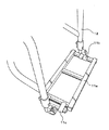
図3は、フットレストの垂直フレーム12がアウターパイプ18と伸縮部材21を装着したインナーパイプ19とよりなり、該伸縮部材21を装着して伸縮自在としたインナーパイプ19の下端部にフットレスト11を着設して、伸縮部材21を着設したインナーパイプ19の上端部と主車輪15を固定するブレーキ22とをワイヤ23で接続した本発明のフットレスト機構100を示している。主車輪を固定するブレーキ22と本発明のフットレスト機構100をワイヤ23で接続することによって、フットレスト11を踏むと伸縮自在のインナーパイプ19が下がって、インナーパイプ19の上端に結索されたワイヤ23が引かれて、ブレーキ22が作動して主車輪15を固定する。車椅子に乗降する際にブレーキ22をかけ忘れて、車椅子が急に動き出して転倒する等の不測の事故を防止する。
In FIG. 3, the
図4は、垂直フレーム12のアウターパイプ18に伸縮部材21を挿着したインナーパイプ19を挿着して、インナーパイプ19の下端部にフットレスト11を装着した本発明のフットレスト機構100を示している。ここで挿着する伸縮部材21は、バネを利用した伸縮部材21であっても、ガス圧、油圧を利用した伸縮部材21であっても良く、フットレスト11に体重がかかった時、インナーパイプ19が下降するものであればよく、伸縮部材21の種類は特に限定されるものではない。
FIG. 4 shows the
図5は、本発明のフットレスト機構100に着設するフットレスト11の枠が、1つの枠よりなるフットレスト11の枠を例示している。フットレスト11を使用する時は、1つの枠11a上には、滑り止めの着いたプラスチック製の踏板等を装着して使用する。フットレスト11の枠11aの一方端は蝶番11bを付けてフットレスト枠11aを開閉自在として、他方端にフットレスト11の枠11a受ける掛け金11cを着設してフットレスト11を固定する。フットレスト11の枠11aを1枚の踏み板ですると、片足を乗せただけでフットレスト11が下降する利点を有しており、左右2枚に分割されているフットレスト11に比べて、左右のフットレスト11を片方ずつ上げ下げする手間が省ける。
FIG. 5 illustrates a frame of the
図6は、フットレスト11を1枚の踏み板で作成したフットレストの枠11aを着設したフットレスト11の正面から示している。フットレスト11の枠11aの一方端11cは蝶番11bによって開閉自在に軸着されている。図6では、フットレスト11の枠11aの他方端の固定は、下からフットレスト11を受けて支えるための受け金具11cを着設した例を示している。スライディングカラー26及び摺動溝27は図8において説明する。
FIG. 6 shows the
図7は、本発明のフットレスト機構100のフットレスト11が左右2枚のフットレスト11よりなる例を示している。フットレスト11は、先に示したようにフットレスト11の枠11aとそれに乗せる踏み板と別体として着設してもよい。また、本図7のように2枚のフットレスト11、あるいは一体成型したフットレスト板を作成して使用してもよく、フットレスト11の形状は特に限定されるものではない。図7に示す左右2枚のフットレスト11の端部は、蝶番によって左右に開閉自在に軸着し、フットレスト11の開閉は左右2枚の中央の端部を持ち上げることによって、左右2枚のフットレスト11をそれぞれ別々に、又は同時に開閉することができる。
FIG. 7 shows an example in which the
図8は、本発明のフットレスト機構100の構成物品と、フットレスト11の垂直フレーム12に伸縮部材21を挿入する方法を例示する。垂直フレーム12のアウターパイプ18の下部管口に伸縮部材21のストッパー24を装着して、ネジ24aで強固に固定する。インナーパイプ19に伸縮部材21を挿入して、伸縮部材21の上部ピン孔21aとインナーパイプ19のピン孔21aでピン25を用いて挿着する。次いで、伸縮部材21を挿着したインナーパイプ19をアウターパイプ18に挿入して、伸縮部材21の下部21bを、アウターパイプ18に着設したストッパー24の下部のネジ孔24bを通して、スライディングカラー26でインナーパイプ19の摺動溝27内を通して、インナーパイプ19を摺動可能に着設する。インナパイプ19は摺動溝27の範囲で上下に伸縮可能となる。
FIG. 8 illustrates a component of the
図9には、垂直フレーム12のインナーパイプ19に伸縮部材21を挿着してアウターパイプ18に挿入し、インナーパイプ19の下端部にフットレスト11を装着した断面図を示す。アウターパイプ18の管口部に着設されたストッパー24は、アウターパイプ18にネジ24aで強固に固定する。ストッパー24の下部にスライディングカラー26を用いて、インナーパイプ19の摺動溝27を通してナット26aで固定する。スライディングカラー26で固定した伸縮部材21を挿着したインナーパイプ19は図6、図7、又は図8に示す摺動溝27の範囲内で上下に伸縮して、フットレスト機構100のフットレスト11を上下させることができる。
FIG. 9 shows a cross-sectional view in which the
図10は、垂直フレーム12のアウターパイプ18に伸縮部材21を挿着したインナーパイプ19を挿入して、インナーパイプ19の下端部にフットレスト11を装着した本発明のフットレスト機構100の断面図を示している。アウターパイプ18の管口部に着設されたストッパー24はネジ24aで固定されており、スライディングカラー26はアウターパイプ18に穿設された摺動溝と、インナーパイプ19を貫通してナット26aで固定されている。
FIG. 10 shows a cross-sectional view of the
図11は、垂直フレーム12のアウターパイプ18に伸縮部材21を挿着したインナーパイプ19を挿入して、インナーパイプ19の下端部にフットレスト11を装着した断面図を示す。図11は本発明のフットレスト機構100のフットレスト11が下降した状態を示している。
FIG. 11 shows a cross-sectional view in which the
図12は、垂直フレーム12のアウターパイプ18に伸縮部材21を挿着したインナーパイプ19を挿入して、伸縮部材21を挿着したインナーパイプ19の伸縮を係止する係止部28をアウターパイプ19の側面に着設してワイヤ23aでアームレスト13の下部に着設したグリップ式の操作レバー29に連結した車椅子を示す。グリップ式の操作レバー29は、最初(一回目)に操作レバーを握るとインナーパイプ19の係止が解除されて、フットレスト11に足を乗せて、体重を掛けていくと伸縮部材を挿着したインナーパイプ19が下降する。フットレスト11が接地状態にあるか、若しくは、任意の高さで操作レバー29を離すと伸縮部材を挿着したインナーパイプ19が固定される。再度(二回目)操作レバー29を握ると係止が解除されて伸縮部材を挿着したインナーパイプ19が収縮して、フットレスト11が上昇し、任意の位置で操作レバー29を離すとその位置でフットレスト11が固定される。操作レバー29は2段階操作として、操作の間にフットレストを固定する操作を入れて、不測の事故を防止するようにした。
In FIG. 12, the
図13は、垂直フレーム12のアウターパイプ18に伸縮部材21を挿着したインナーパイプ19を挿入して、伸縮部材21を装着したインナーパイプ18の伸縮を係止する係止部材28をアウターパイプ19の側面に着設した例を示す。アウターパイプ18の側面に着設する係止部材28は図13の(13−1)に示すように、アウターパイプ18の側面に固定部28aを着設する。次いで、図13の(13−2)に示すように、ワイヤ23に接続されたバネ28cが付勢された押圧部28bの係合固定部28dを前記固定部28aに係合固定する。ワイヤ23はアームレスト13の下部に着設された操作レバー29に接続する。
In FIG. 13, the
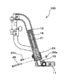
図14は、垂直フレーム12のアウターパイプ18に伸縮部材21を挿着したインナーパイプ19を挿入して、アウターパイプ18の側面に伸縮部材21を挿着したインナーパイプ19の伸縮を係止する係止部材28を着設してワイヤ23aでアームレスト13の下部に着設したグリップ式の操作レバー29に連結し、伸縮部材21を挿着したインナーパイプ19の上端部の係着部31にワイヤ23bを接続して、主車輪のブレーキ部30に接続した車椅子を示す。伸縮部材21が伸びてワイヤ23bが引かれると、主車輪にブレーキが掛かかり、フットレスト11が下降して、座乗者が乗り降りする際には、車椅子はブレーキ30で係止されて、安心して乗り降りすることができる。本発明のフットレスト機構に接続した車椅子の主車輪のブレーキはドラムブレーキを使用したが、他のディスクブレーキであっても良い。
FIG. 14 shows a mechanism for inserting the
図15は、垂直フレーム12のアウターパイプ18に伸縮部材21を挿着したインナーパイプ19の伸縮を係止する係止部材28をアウターパイプ19の側面に着設してワイヤ23aに接続して、該ワイヤ23aを車椅子の側面に沿って後部に回し、車椅子の後部からワイヤ23aを跳ね上げ式アームレスト13の下部に着設したグリップ式の操作レバー29に連結した。さらに、伸縮部材21を装着したインナーパイプ19の上端部からワイヤ23bで主車輪のブレーキ部30に接続した跳ね上げ式アームレストを有する車椅子を示す。
FIG. 15 shows that a locking
100:フットレスト機構
10:車椅子
11:フットレスト
12:垂直フレーム
13:アームレスト
14:キャスター
15:主車輪
16:座部
17:背もたれ
18:アウターパイプ
19:インナーパイプ
20:バネ部材
21:伸縮部材
22:ブレーキ
23:ワイヤ
24:ストッパー
25:ピン
26:スライディングカラー
27:摺動
28:係止部
29:操作レバー
30:主車輪のブレーキ部
100: footrest mechanism 10: wheelchair 11: footrest 12: vertical frame 13: armrest 14: caster 15: main wheel 16: seat 17: backrest 18: outer pipe 19: inner pipe 20: spring member 21: telescopic member 22: brake 23: Wire 24: Stopper 25: Pin 26: Sliding collar 27: Sliding 28: Locking portion 29: Operation lever 30: Main wheel brake portion
Claims (9)
前記フットレストに足を安定的に載置すべく、前記フットレストに体重がかかると前記フットレストが下降し、前記フットレストから体重が移ると前記フットレストが上昇するように、前記垂直フレームが伸縮自在に構成されていることを特徴とするフットレスト機構。 A footrest to stabilize by placing the foot on the front of the wheelchair, and rotatable caster, a wheelchair which have a a seat and main wheels at the rear of the pivoting freely caster, of the vehicle chair The vertical frame of the footrest consists of an outer pipe and an inner pipe, a spring member is inserted into the inner pipe, the inner pipe can be slid within the outer pipe, and a footrest is attached to the lower end of the inner pipe The footrest mechanism
In order to stably place the foot on the footrest, the vertical frame is configured to be stretchable so that when the weight is applied to the footrest, the footrest is lowered, and when the weight is moved from the footrest, the footrest is raised. footrest mechanism, characterized in that is.
前記フットレストに足を安定的に載置すべく、前記フットレストに体重がかかると前記フットレストが下降し、前記フットレストから体重が移ると前記フットレストが上昇するように、前記垂直フレームが伸縮自在に構成されていることを特徴とするフットレスト機構。 A footrest to stabilize by placing the foot on the front of the wheelchair, and rotatable caster, a wheelchair which have a a seat and main wheels at the rear of the pivoting freely caster, of the vehicle chair vertical frame of the footrest is more the outer pipe and the inner pipe, wherein by inserting the elastic member into the inner pipe, wherein a slidable said inner pipe within the outer pipe, the inner pipe is inserted the elastic member A footrest mechanism with a footrest attached to the lower end of the
In order to stably place the foot on the footrest, the vertical frame is configured to be stretchable so that when the weight is applied to the footrest, the footrest is lowered, and when the weight is moved from the footrest, the footrest is raised. footrest mechanism, characterized in that is.
Priority Applications (1)
| Application Number | Priority Date | Filing Date | Title |
|---|---|---|---|
| JP2007167559A JP5065778B2 (en) | 2006-09-13 | 2007-06-26 | Wheelchair footrest mechanism |
Applications Claiming Priority (3)
| Application Number | Priority Date | Filing Date | Title |
|---|---|---|---|
| JP2006247566 | 2006-09-13 | ||
| JP2006247566 | 2006-09-13 | ||
| JP2007167559A JP5065778B2 (en) | 2006-09-13 | 2007-06-26 | Wheelchair footrest mechanism |
Publications (2)
| Publication Number | Publication Date |
|---|---|
| JP2008093411A JP2008093411A (en) | 2008-04-24 |
| JP5065778B2 true JP5065778B2 (en) | 2012-11-07 |
Family
ID=39376874
Family Applications (1)
| Application Number | Title | Priority Date | Filing Date |
|---|---|---|---|
| JP2007167559A Active JP5065778B2 (en) | 2006-09-13 | 2007-06-26 | Wheelchair footrest mechanism |
Country Status (1)
| Country | Link |
|---|---|
| JP (1) | JP5065778B2 (en) |
Cited By (1)
| Publication number | Priority date | Publication date | Assignee | Title |
|---|---|---|---|---|
| US11260784B2 (en) | 2019-03-29 | 2022-03-01 | Honda Motor Co., Ltd. | Active vehicle footrest |
Families Citing this family (15)
| Publication number | Priority date | Publication date | Assignee | Title |
|---|---|---|---|---|
| JP5328272B2 (en) * | 2008-09-11 | 2013-10-30 | トヨタ自動車株式会社 | Mobile body and control method thereof |
| DE102010060816B4 (en) * | 2010-11-25 | 2012-09-13 | Sunrise Medical Gmbh & Co. Kg | Width-adjustable footrest for a wheelchair and folding wheelchair hereby |
| JP2012205678A (en) * | 2011-03-29 | 2012-10-25 | Kyb Co Ltd | Wheelchair brake device |
| JP2012205675A (en) * | 2011-03-29 | 2012-10-25 | Kyb Co Ltd | Footrest device for wheelchair |
| JP2012205677A (en) * | 2011-03-29 | 2012-10-25 | Kyb Co Ltd | Footrest device for wheelchair |
| JP5811767B2 (en) * | 2011-10-27 | 2015-11-11 | トヨタ自動車株式会社 | Transfer device and transfer method |
| JP5240744B1 (en) * | 2012-08-30 | 2013-07-17 | 和宏 亀田 | Wheelchair auxiliary brake device |
| JP5414005B1 (en) * | 2012-12-17 | 2014-02-12 | 芳隆 秋野 | wheelchair |
| JP6237345B2 (en) * | 2014-03-03 | 2017-11-29 | トヨタ自動車株式会社 | Thermoelectric generator |
| EP3437614A4 (en) * | 2016-03-31 | 2020-04-15 | Young Bae You | Footrest device and safety device for wheelchair |
| KR101803827B1 (en) * | 2016-03-31 | 2017-12-04 | 유영배 | Leg-rest Device For Wheelchair |
| KR101803829B1 (en) * | 2016-04-14 | 2018-01-10 | 유영배 | Safty Device For Wheelchair |
| JP2018029797A (en) * | 2016-08-25 | 2018-03-01 | 株式会社森山鉄工 | Wheelchair including liftable foot support |
| KR101982318B1 (en) * | 2017-07-17 | 2019-05-24 | 이일열 | Foot-rest assembly for wheelchair |
| JP7268627B2 (en) * | 2020-03-13 | 2023-05-08 | マツダ株式会社 | wheelchair |
Family Cites Families (6)
| Publication number | Priority date | Publication date | Assignee | Title |
|---|---|---|---|---|
| JPS5229043A (en) * | 1975-08-26 | 1977-03-04 | Shitsupusoopu Ruuzu Edowaado | Patient*s wheeled chair |
| US5358266A (en) * | 1993-07-12 | 1994-10-25 | Salem Home Inc. | Wheel chair electric brake and pedal safety kit |
| JPH0994270A (en) * | 1995-09-28 | 1997-04-08 | Atex Co Ltd | Wheelchair which allows user to sit in or rise from easily |
| JP2001046441A (en) * | 1999-08-09 | 2001-02-20 | Matsunaga Seisakusho:Kk | Telescopic locking mechanism for use with wheelchair |
| JP3516340B2 (en) * | 2001-01-26 | 2004-04-05 | パラマウントベッド株式会社 | wheelchair |
| JP3543962B2 (en) * | 2001-04-06 | 2004-07-21 | 日進医療器株式会社 | wheelchair |
-
2007
- 2007-06-26 JP JP2007167559A patent/JP5065778B2/en active Active
Cited By (1)
| Publication number | Priority date | Publication date | Assignee | Title |
|---|---|---|---|---|
| US11260784B2 (en) | 2019-03-29 | 2022-03-01 | Honda Motor Co., Ltd. | Active vehicle footrest |
Also Published As
| Publication number | Publication date |
|---|---|
| JP2008093411A (en) | 2008-04-24 |
Similar Documents
| Publication | Publication Date | Title |
|---|---|---|
| JP5065778B2 (en) | Wheelchair footrest mechanism | |
| US3679257A (en) | Foldable wheel chair | |
| US9301895B2 (en) | Medical support apparatus | |
| US5161812A (en) | Travel-lift chair | |
| US8122534B2 (en) | Multi-position support for a folding patient lift device | |
| US6623022B2 (en) | Folding commode and shower wheelchair | |
| EP0976377A2 (en) | Chairs | |
| AU2009209080A1 (en) | Systems and methods for assisting a seated person to a standing position | |
| GB1572205A (en) | Transportation of disabled or invalided persons | |
| JP2016193100A (en) | Support machine for standing-up and sitting-down, and walking in standing position | |
| US6176508B1 (en) | Advanced commode-shower wheelchair | |
| US11523953B2 (en) | Wheelchair egress system | |
| US6155583A (en) | Wheelchair | |
| US20060208552A1 (en) | Laterally adjustable armrest assembly | |
| JP4730859B1 (en) | wheelchair | |
| GB2561810A (en) | Powered seat and related seating improvements | |
| CN213963996U (en) | Wheel chair | |
| JP5067806B2 (en) | Reclining wheelchair | |
| JP5204688B2 (en) | Automatic wheelchair locking mechanism | |
| JP4567610B2 (en) | wheelchair | |
| JPH0337063A (en) | Reclining backrest assembly for wheelchair | |
| JP2012152297A (en) | Standing-up assisting chair | |
| JP2012217718A (en) | Handrail for toilet bowl | |
| JP2008237583A (en) | Wheelchair for assistance and footrest assembly used therefor | |
| JP3610531B2 (en) | wheelchair |
Legal Events
| Date | Code | Title | Description |
|---|---|---|---|
| A621 | Written request for application examination |
Free format text: JAPANESE INTERMEDIATE CODE: A621 Effective date: 20100416 |
|
| RD02 | Notification of acceptance of power of attorney |
Free format text: JAPANESE INTERMEDIATE CODE: A7422 Effective date: 20100416 |
|
| A977 | Report on retrieval |
Free format text: JAPANESE INTERMEDIATE CODE: A971007 Effective date: 20120229 |
|
| A131 | Notification of reasons for refusal |
Free format text: JAPANESE INTERMEDIATE CODE: A131 Effective date: 20120417 |
|
| A521 | Request for written amendment filed |
Free format text: JAPANESE INTERMEDIATE CODE: A523 Effective date: 20120615 |
|
| TRDD | Decision of grant or rejection written | ||
| A01 | Written decision to grant a patent or to grant a registration (utility model) |
Free format text: JAPANESE INTERMEDIATE CODE: A01 Effective date: 20120717 |
|
| A01 | Written decision to grant a patent or to grant a registration (utility model) |
Free format text: JAPANESE INTERMEDIATE CODE: A01 |
|
| A61 | First payment of annual fees (during grant procedure) |
Free format text: JAPANESE INTERMEDIATE CODE: A61 Effective date: 20120810 |
|
| R150 | Certificate of patent or registration of utility model |
Ref document number: 5065778 Country of ref document: JP Free format text: JAPANESE INTERMEDIATE CODE: R150 Free format text: JAPANESE INTERMEDIATE CODE: R150 |
|
| FPAY | Renewal fee payment (event date is renewal date of database) |
Free format text: PAYMENT UNTIL: 20150817 Year of fee payment: 3 |
|
| R250 | Receipt of annual fees |
Free format text: JAPANESE INTERMEDIATE CODE: R250 |
|
| R250 | Receipt of annual fees |
Free format text: JAPANESE INTERMEDIATE CODE: R250 |
|
| R250 | Receipt of annual fees |
Free format text: JAPANESE INTERMEDIATE CODE: R250 |
|
| R250 | Receipt of annual fees |
Free format text: JAPANESE INTERMEDIATE CODE: R250 |
|
| R250 | Receipt of annual fees |
Free format text: JAPANESE INTERMEDIATE CODE: R250 |
|
| R250 | Receipt of annual fees |
Free format text: JAPANESE INTERMEDIATE CODE: R250 |
|
| R250 | Receipt of annual fees |
Free format text: JAPANESE INTERMEDIATE CODE: R250 |
|
| R250 | Receipt of annual fees |
Free format text: JAPANESE INTERMEDIATE CODE: R250 |
|
| R250 | Receipt of annual fees |
Free format text: JAPANESE INTERMEDIATE CODE: R250 |