JP5061900B2 - Steering column device - Google Patents
Steering column device Download PDFInfo
- Publication number
- JP5061900B2 JP5061900B2 JP2007528253A JP2007528253A JP5061900B2 JP 5061900 B2 JP5061900 B2 JP 5061900B2 JP 2007528253 A JP2007528253 A JP 2007528253A JP 2007528253 A JP2007528253 A JP 2007528253A JP 5061900 B2 JP5061900 B2 JP 5061900B2
- Authority
- JP
- Japan
- Prior art keywords
- teeth
- tooth
- telescopic
- angle
- steering
- Prior art date
- Legal status (The legal status is an assumption and is not a legal conclusion. Google has not performed a legal analysis and makes no representation as to the accuracy of the status listed.)
- Active
Links
Images


Classifications
-
- B—PERFORMING OPERATIONS; TRANSPORTING
- B62—LAND VEHICLES FOR TRAVELLING OTHERWISE THAN ON RAILS
- B62D—MOTOR VEHICLES; TRAILERS
- B62D1/00—Steering controls, i.e. means for initiating a change of direction of the vehicle
- B62D1/02—Steering controls, i.e. means for initiating a change of direction of the vehicle vehicle-mounted
- B62D1/16—Steering columns
- B62D1/18—Steering columns yieldable or adjustable, e.g. tiltable
- B62D1/184—Mechanisms for locking columns at selected positions
Description
【技術分野】
【0001】
本発明は、ステアリングシャフトを、チルト方向及びテレスコ方向の少なくとも一方に対して調整可能に支持するステアリングコラム装置に関する。
【背景技術】
【0002】
ステアリングコラム装置は、車両の重要安全保安部品であり、衝突時に乗員の安全を確保するために衝突時におけるその挙動を、どのように制御するかが非常に重要である。通常は、ステアリングコラム装置自体に衝撃エネルギー吸収機構を設けるともに、ステアリングホイール内に収納したエアーバッグの支持部材としても重要な役割を担っている。
【0003】
一方、運転者の運転姿勢を最適にするために、一般的なステアリングコラム装置は、運転者の体格や運転姿勢に応じて、ステアリングホイールの傾斜角度を調整でき、ステアリングホイールの軸線方向位置を調整できるようになっている。従って、ステアリングコラム装置には、コラム本体(即ちステアリングホイール)の位置や姿勢の調整が容易でなければならず、且つ衝突時には所定の位置や姿勢を確保しなければならないという相反する機能が必要になる。このような相反する機能を両立させるべく、従来のステアリングコラム装置では、種々の工夫がなされているが、ユーザーの操作性に対する要求の高まりなどにより、更なる向上が求められている。
【0004】
ここで、特許文献1においては、多板の摩擦プレートを重合させ、その間に発生する摩擦力を用いて、コラム本体を保持できるステアリングコラム装置が開示されている。
【特許文献1】
特開平10−35511号公報
【特許文献2】
独国特許第10212263号明細書
【特許文献3】
米国特許公開第2005/0016315A1号明細書
【発明の開示】
【発明が解決しようとする課題】
【0005】
ところが、多板の摩擦プレートを重合させる機構では、構成が複雑となり、またチルト・テレスコピック調整時に多板の摩擦プレート同士がこすれ合う振動が操作者に伝わりやすく、操作フィーリングが悪いという問題もある。又、部品点数が増えるため、組立工数が増大するといった問題がある。
【0006】
一方、特許文献2においては、チルト・テレスコピック調整時には、噛合していたギヤ同士を離脱させ、調整後においては、ギヤ同士を噛合させることで、コラム本体の位置を確実に保持することができるステアリングコラム装置が開示されている。しかしながら、特許文献2に示すようにギヤを噛合させてコラム本体の位置を保持する機構の場合、調整後においてギヤを噛合させる際に、ギヤの山同士が当接し合うことで本来的に噛合不良が発生する恐れがある。特許文献2では、これを抑制しようと試みがなされているが、必ずしも十分とはいえない。
【0007】
更に、特許文献3においては、チルト・テレスコピック調整後に、ばね付勢され移動可能に保持された一方の歯を他方の歯にスムーズに係合させることができ、それによりコラム本体の位置を保持できるステアリングコラム装置が開示されている。しかしながら、かかる構成では、一方の歯をばね付勢するために複雑且つ大型化した構造を用いなければならないという問題がある。
【0008】
また、歯を噛合させるタイプのステアリングコラム装置において、衝突時にステアリングシャフトに力が付与されたとき、これに抗することができる保持力を高めるためには、噛合する歯数を増大させることが考えられる。しかしながら、噛合する歯数を増大させると、位置調整後におけるかみ合い不良が生じやすくなり、またその分だけ設置スペースが必要となるという問題がある。
【課題を解決するための手段】
【0009】
本発明は、かかる従来技術の問題点に鑑みてなされたものであり、軽量且つコンパクトでありながら、保持力を高めることができ、又操作フィーリングに優れたステアリングコラム装置を提供することを目的とする。
【0010】
本発明の第1の観点によれば、ステアリングシャフトを、チルト方向及びテレスコピック方向の少なくとも一方に対して位置調整可能に支持するステアリングコラム装置において、
車体側に固定された第1の歯と、
ステアリングシャフトを回転自在に支持するコラム本体と、
前記コラム本体と一体的に移動する第2の歯とを有し、
前記第1の歯と前記第2の歯とが、互いに噛合して、前記コラム本体を前記車体に対して位置決めし、
前記第1の歯と前記第2の歯とが、互いに離間して、前記コラム本体を前記車体に対して位置調整可能な状態とし、
前記第1の歯が第2の歯と噛み合う直前から互いの噛合が完了する間、前記第1の歯に対する前記第2の歯の接近方向が、それぞれの歯筋方向に対してなす角度を0度より大きく、90度未満に設定されるように、前記第1の歯と第2の歯は接近されて噛合し、
前記第1の歯及び前記第2の歯の一方は、対向する一対の第1傾斜面に設けられ、
前記第1の歯及び前記第2の歯の他方は、前記一対の第1傾斜面に各々対向する一対の第2傾斜面に形成される。
【0012】
本発明の第2の観点によれば、第1の観点によるステアリングコラム装置であって、
前記第1,2の歯が互いに離脱した状態で、前記一対の第1傾斜面間で定義される第1傾斜面の中心面と、前記一対の第2傾斜面間で定義される第2傾斜面の中心面とが互いにずれて配置され、
前記第1の歯を前記第2の歯に噛み合せる前に、前記第1傾斜面の中心面と、前記第2傾斜面の中心面とを近づけるように駆動する駆動手段を有する。
【0013】
本発明の第3の観点によれば、第1又は2の観点によるステアリングコラム装置であって、前記第1の歯及び前記第2の歯のうちの一方の歯に連結されたレバーを回転移動させることにより、前記レバーと共に円弧状の軌跡を有するように移動する前記一方の歯が、前記第1の歯及び前記第2の歯のうちの他方の歯に係合させてもよい。
【0014】
本発明の第4の観点によれば、第1又は2の観点によるステアリングコラム装置であって、前記第1の歯及び前記第2の歯のうちの少なくとも一方の歯は、先端に向かうにつれて歯の断面積が小さく形成されていてもよい。
【0015】
本発明の第5の観点によれば、第1の観点によるステアリングコラム装置はさらに、
車体側に固定されるブラケットと、
前記ブラケットに揺動可能に取り付けられて前記コラム本体と共にチルト移動するレバーを有し、
前記第1の歯は前記車体側に固定された前記ブラケットに設けられ、
前記第2の歯は前記コラム本体と共にチルト移動する前記レバーに設けられていてもよい。
【0016】
本発明の第6の観点によれば、第1の観点によるステアリングコラム装置は
車体側に固定されるブラケットに揺動可能に支持されたレバーを有し、
前記レバーの回動に伴い、前記コラム本体を前記レバーに対するテレスコ移動が許容され、
前記第1の歯は、前記車体側に支持されたレバーに設けられ、
前記第2の歯は、前記テレスコ移動するコラム本体に設けられていてもよい。
【0017】
本発明の第7の観点によれば、第1の観点によるステアリングコラム装置であって、
前記一対の第1傾斜面は所定角度を有して向かい合い、くさび形を形成し、
前記一対の第2傾斜面も所定角度を有して向かい合い、くさび形を形成していてもよい。
【0018】
本発明の第8の観点によれば、第1の観点によるステアリングコラム装置であって
前記第1の歯と前記第2の歯とは、前記ステアリングシャフトに力が与えられた場合に、噛み合い率が高くなる方向に歯筋が傾斜していてもよい。
【0019】
本発明の第9の観点によれば、第8の観点によるステアリングコラム装置であって、
前記第1の歯と前記第2の歯の間の摩擦角をμ、
前記第1の歯と前記第2の歯の半頂角をα、
前記第1の歯の歯面と前記第2の歯の歯面が、噛合面に対して成す角度をβ、
前記第1の歯と前記第2の歯筋の方向が前記力の方向となす角度をγと定義したとき、
以下の条件式を満たすように歯面が配置される。
μ>tan−1(tanα・sinβ)−(90°−γ) (条件式)
ここで、噛み合い面とは、第1の歯と第2の歯が噛み合ってから、その噛み合い率が増加するように一方の歯を移動させる際に、その一方の歯の長軸が形成する軌跡に沿う面である。
【0020】
本発明の第10の観点によれば、ステアリングシャフトを、チルト方向及びテレスコピック方向の少なくとも一方に対して位置調整可能に支持するステアリングコラム装置において、
車体側に固定された第1の歯と、
ステアリングシャフトを回転自在に支持するコラム本体と、
前記コラム本体と一体的に移動する第2の歯とを有し、
前記第1の歯と前記第2の歯とが、互いに噛合して、前記コラム本体を前記車体に対して位置決めし、
前記第1の歯と前記第2の歯とが、互いに離間して、前記コラム本体を前記車体に対して位置調整可能な状態とし、
前記第1の歯と前記第2の歯とは、前記ステアリングシャフトに力が与えられた場合に、噛み合い率が高くなる方向に歯筋が傾斜しており、
前記第1の歯及び前記第2の歯の一方は、対向する一対の第1傾斜面に設けられ、
前記第1の歯及び前記第2の歯の他方は、前記一対の第1傾斜面に各々対向する一対の第2傾斜面に形成されている。
【0022】
本発明の第11の観点によれば、第10の観点によるステアリングコラム装置であって、
前記一対の第1傾斜面は所定角度を有して向かい合い、くさび形を形成し、
前記一対の第2傾斜面も所定角度を有して向かい合い、くさび形を形成してもよい。
【0023】
本発明の第12の観点によれば、第10の観点によるステアリングコラム装置であって、
前記第1の歯と前記第2の歯の間の摩擦角をμ、
前記第1の歯と前記第2の歯の半頂角をα、
前記第1の歯の歯面と前記第2の歯の歯面が、噛合面に対して成す角度をβ、
前記第1の歯と前記第2の歯筋の方向が前記力の方向となす角度をγと定義したとき、
以下の条件式を満たすように歯面が配置されていてもよい。
μ>tan−1(tanα・sinβ)−(90°−γ) (条件式)
【発明の効果】
【0024】
複数の直線状の歯を有するギア形状の部品を噛み合わせる場合、通常次の二つの例が考えられる。一つ目の例として、歯同士を歯筋に対して法線方向に互いに向かい合わせ、それから平行移動させることにより噛合する。二つ目の例として、向かい合う歯同士が、歯筋の接線方向に平行に移動して噛み合う。どちらの例の場合にも、噛み合うギアの歯先同士、または歯筋の先端同士が当たり、噛合不良が発生する可能性が高い。ここで、「歯筋の法線方向」とは、同じギア部品において複数の歯筋を含む仮想面に対し、当該歯筋上から延在する法線をいうものとする。
【0025】
これに対し、本発明のステアリングコラム装置によれば、前記第1の歯と前記第2の歯とは、それぞれの歯筋に対して法線方向及び接線方向(接線に平行な方向を含む)以外の方向に沿って接近させて噛合させるようになっているので、前記第1の歯と前記第2の歯の噛合不良を抑制できる。従って、多板の摩擦プレートを用いたときのように操作フィーリングが悪くなることが回避され、更に前記第1の歯と前記第2の歯が噛合した後は、大きな保持力を発揮できる。特に、前記第1の歯と前記第2の歯の最初の噛合が生じたときから、両者を歯筋方向に摺動させつつ噛み合い率を高めるようにすると、スムーズな噛合を行えるので好ましい。なお、本明細書中、「テレスコ方向」とはステアリングシャフトの軸線方向をいい、「チルト方向」とは、それに交差する方向(特に上下方向)をいうものとする。
【0026】
更に、前記第1の歯及び前記第2の歯は、対向するテーパ面の両面に形成されていると、両面における歯同士の噛合により、より強固な保持力を発揮できる。
【0027】
更に、離脱した状態で、前記第1の歯のテーパ面の中心面と、前記第2の歯のテーパ面の中心面とがズレており、噛合時に、前記第1の歯のテーパ面の中心面と、前記第2の歯のテーパ面の中心面とを近づけるように駆動する駆動手段を有すると、より円滑な噛合を実現できる。
【0028】
前記第1の歯及び前記第2の歯のうちの一方の歯に連結されたレバーを回転移動させることにより、前記レバーと共に円弧状に移動する前記一方の歯が、前記第1の歯及び前記第2の歯のうちの他方の歯に係合するようになっていると、簡素な構成で確実な動作を実現できる。
【0029】
前記第1の歯及び前記第2の歯のうちの少なくとも一方の歯は、先端に向かうにつれて歯の断面積が小さくなっていると、前記第2の歯と噛合しやすいので好ましい。
【0030】
本発明のステアリングコラム装置によれば、前記第1の歯と前記第2の歯とは、衝突時に前記ステアリングシャフトに力が与えられた場合に、かみ合い率が高くなる方向に歯筋が傾斜しているので、前記ステアリングシャフトに与えられる衝撃力が大きければ大きいほど、よりかみ合い率が高まり、保持力を向上させることができる。又、歯数を少なく抑えても保持力を確保することができるので、軽量且つコンパクトでありながら、良好な操作フィーリングを確保できるという利点もある。
【0031】
更に、前記第1の歯と前記第2の歯の一方は、向かい合ったテーパ面に形成され、他方は、背中合わせのテーパ面に形成されていると、衝突時にかみ合い率を高めることができる。
【0032】
更に、θが摩擦角を越えないように三次元的にある一定の関係式により歯面角度α、β、γ、θを設定することで、歯筋方向の噛み合い長さの減少と、噛み合い率の低下を防止でき、ひいては過大な荷重が作用した際にも噛み合う歯が外れないという効果を奏する。
【図面の簡単な説明】
【0033】
【図1】本実施の形態に係るステアリングコラム装置の斜視図である。
【図2】変形例に係るステアリングコラム装置の斜視図である。
【図3】噛合状態にあるテレスコ用ギアベース6とテレスコ用ギア部材8の斜視図である。
【図4】離脱状態にあるテレスコ用ギアベース6とテレスコ用ギア部材8の断面図である。
【図5】(a)〜(e)は離脱状態から噛合状態に至るテレスコ用ギアベース6とテレスコ用ギア部材8の断面図である。
【図6】チルト用ギアベース7とチルト用ギア部材9との関係を示す斜視図である。
【図7】本実施の形態にかかるテレスコ用ギアベース6とテレスコ用ギア部材8の変形例を示す斜視図である。
【図8】本実施の形態にかかるテレスコ用ギアベース6とテレスコ用ギア部材8の変形例を示す断面図である。
【図9】本実施の形態にかかるチルト用ギアベース7とチルト用ギア部材9の変形例を示す、図6と同様な断面図である。
【図10】テレスコ用ギアベース6及びテレスコ用ギア部材8の製造方法を示すフローチャートである。
【図11】(a)〜(g)はテレスコ用ギア部材8の加工状態を、製造工程順に示す図である。
【図12】(a)〜(e)はテレスコ用ギアベース6の加工状態を、製造工程順に示す図である。
【図13】テレスコ用ギア部材8の加工を行うダイスを示す図であり、(a) はその上面図、(b)はその側面図である。
【図14】変形例に係るステアリングコラム装置の斜視図である。
【図15】変形例に係るステアリングコラム装置の斜視図である。
【図16】変形例に係るステアリングコラム装置のコラム本体の斜視図である。
【図17】(a)〜(c)は別な実施の形態にかかるテレスコ用ギアベース6とテレスコ用ギア部材8の断面図である。
【図18】テレスコ用ギアベース6の歯6aの一つの斜視図である。
【図19A】第2実施例にかかる、通常時におけるテレスコ用ギアベース6及びテレスコ用ギア部材8を示す図である。
【図19B】図19AのXIX B矢視図である。
【図19C】図19AのXIX C矢視図である。
【図20A】第2実施例にかかる、衝突時におけるテレスコ用ギアベース6及びテレスコ用ギア部材8を示す図である。
【図20B】図20AのXX B矢視図である。
【図20C】図20AのXX C矢視図である。
【図21】第3実施例を説明するための従来のステアリングコラム装置を示す図である。
【図22】第3実施例を説明するための従来のギア機構を示す図である。
【図23A】第3実施例において、歯面の傾斜角をβ、歯筋の傾斜角を0度に設定した場合のギア部材の側面図である。
【図23B】図23Aの左方向から図23Aを見たギア部材の正面図である。
【図23C】図23Aの要部拡大図である。
【図23D】図23Bの要部拡大図である。
【図23E】図23CのXXIII E矢視図である。
【図24】図23Cにおいて、歯筋の傾斜角がγ度傾斜した場合のギア部材を示すである。
【図25】第4実施例を説明するための、一組の歯面によりギアの噛合が構成されている場合を示す比較図である。
【図26】第4実施例のギア部材を示す斜視図である。
【発明を実施するための最良の形態】
【0034】
以下、本発明の実施の形態に係るチルト ・テレスコピック式のステアリングコラム装置を図面を参照しつつ説明する。
(第1実施例)
【0035】
図1、2は、本発明の第1実施例に係るステアリングコラム装置の斜視図であり、図1はロック状態を示し、図2は解除状態を示す。
【0036】
円筒状のコラム本体1は、ブラケット2、3を介して不図示の車体に取り付けられるようになっている。コラム本体1内には、不図示のステアリングホイールと操舵機構とを連結するステアリングシャフトSが挿通され、不図示のベアリングにより回転自在に支持されている。
【0037】
コラム本体1の側部には、板状のテレスコ用ギアベース6が固定されており、一方、ブラケット2に板状のチルト用ギアベース7が固定されている。テレスコ用ギアベース6は、コラム本体1におけるテレスコ方向の調整幅に対応した長さを有している。又、チルト用ギアベース7は、コラム本体1におけるチルト方向の調整幅に対応した高さを有している。コラム本体1には、テレスコピックスライド用の長穴が成形されている。
【0038】
ブラケット2に設けられたチルト方向の長孔(不図示)と、コラム本体1に設けられたテレスコ方向の長孔(不図示)を貫通した回動可能なシャフト5aに、操作レバー5が取り付けられている。操作レバー5には、テレスコ用ギアベース6に対応して、テレスコ用ギア部材8が固定的に取り付けられ、チルト用ギアベース7に対応して、チルト用ギア部材9が一体的に形成されている。
【0039】
操作レバー5の根元には、カム式ロータリークランプ機構10が設けられている。カム式ロータリークランプ機構10は、操作レバー5を操作することにより、カム効果によりクランプを発生させて、チルト・テレスコピックを位置決めする作用を有する。又、カム式ロータリークランプ機構10に、操作レバー5のストッパー機能を持たせて、ギアベースとギア部材とのギアの噛み合い率を制御することも可能であるので、操作感に節度を持たせることができる。
【0040】
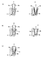
図1に示す位置に操作レバー5を回動させると、テレスコ用ギアベース6に対し、円弧状に移動しながらテレスコ用ギア部材8が噛合し、且つチルト用ギアベース7にチルト用ギア部材9が噛合する。これに対し、図2に示す位置に操作レバー5を回動させると、テレスコ用ギアベース6から、円弧状に移動しながらテレスコ用ギア部材8が離脱し、且つチルト用ギアベース7からチルト用ギア部材9が離脱するようになっている。
【0041】
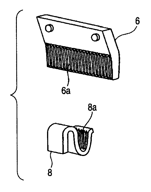
図3は、噛合状態にあるテレスコ用ギアベース6とテレスコ用ギア部材8の斜視図であり、テレスコ用ギア部材8は車体に対して位置決めされた状態にある。図4は、離脱状態にあるテレスコ用ギアベース6とテレスコ用ギア部材8の断面図である。テレスコ用ギアベース6は、下方に向かうにつれて狭幅となるテーパ面の両外面に複数の歯(第1の歯)6aを有し、テレスコ用ギア部材8は、上方に向かうにつれて広幅となるテーパ面の両内面に、同じピッチで複数の歯(第2の歯)8aを有している。
【0042】
本実施の形態では、テレスコ用ギアベース6及びテレスコ用ギア部材8におけるテーパ面のテーパ角κを9°となるように設けてあるが、テーパ角は0度以上の鋭角であれば良い。又、テレスコ用ギアベース6の歯6aの端部(図で下端)を、曲率半径R2で輪郭付けし、それに対向するテレスコ用ギア部材8の歯8aの端部(図で上端)を、曲率半径R3で輪郭付けし、それによりテーパ面同士が嵌合しやすいにようにしている。本実施の形態では、歯6a、8aの端部を円弧で輪郭付けしたが、その曲率半径は任意であり、又必ずしも必要であるわけではない。また円弧でなく直線で輪郭付けしても良い。その場合、歯筋と直線とは任意の曲率半径の円弧で接続させることが望ましい。
【0043】
また、テレスコ用ギアベース6とテレスコ用ギア部材8の歯筋は、操作レバー5のクランプ回転軸を中心とした半径R(図1)の円弧形状に形成すると好ましい。テレスコ用ギア部材8は、操作レバー5に固定されるので、その歯8aの移動軸跡は円弧となる。そのためテレスコ用ギアベース6とテレスコ用ギア部材8の歯筋を、同じ半径Rの円弧状に形成することで、歯6a、8a同士が噛合する際に、操作フィーリングが向上する。
【0044】
図5は、離脱状態から噛合状態に至るテレスコ用ギアベース6とテレスコ用ギア部材8の断面図である。図5を参照して、テレスコ用ギアベース6とテレスコ用ギア部材8の噛合動作について説明する。まず、離脱状態においては、向かい合うテレスコ用ギアベース6の歯6aとテレスコ用ギア部材8の歯8aとは、歯筋の方向がはす向かいの状態になっている(図5(a))。
【0045】
ここから、テレスコ用ギアベース6とテレスコ用ギア部材8とを相対的に接近させると、中心ズレがある場合には、一方の面の歯6aが歯8aの歯先同士(図5(b)のC点)が当接することになるが、それぞれの歯筋に対して法線方向及び接線方向以外の方向に沿って接近させて噛合させているので、C点で当接した後においても、テレスコ用ギアベース6とテレスコ用ギア部材8とは矢印方向(図5(b))に相対移動を続けることができ、スライドしつつ互いに噛み合っていくため、このスライドの最中に歯6a、8aが容易に噛合することができる(図5(c)のD点)。すなわち、テレスコ用ギアベース6とテレスコ用ギア部材8とが互いに噛み合う直前から互いの噛合が完了する間(図5(a)から図5(e))、テレスコ用ギアベース6とテレスコ用ギア部材8の接近方向が、それぞれの歯筋方向に対してなす角度を0度より大きく、90度未満に設定されている。このように両部材を相対的に接近させて噛合を達成する。
【0046】
一方の面の歯6a、8aが噛合すれば、それがガイドとなって、他方の面の歯6a、8aも容易に噛合することができる(図5(d)、(e))。このように、本実施の形態による歯6a、8aの噛合では、従来のギアの噛合と比較して、歯先同士が当接しあって移動が阻止される可能性が低く、操作レバー5の操作フィーリングが向上するといった効果がある。
【0047】
上記の第1実施例の場合、操作レバー5の回動により、それに取り付けられて一体となったテレスコ用ギア部材8を、テレスコ用ギアベース6と噛合させるようにしているので、操作レバー5に付与された力を直接テレスコ用ギア部材8に伝達することで、確実な噛合を行わせることができる。又、操作レバー5の回動量が、そのままテレスコ用ギアベース6とテレスコ用ギア部材8の噛合量となるので、簡素な構成でありながら確実にコラム本体1の固定を実現できる。
【0048】
以上、テレスコ用ギアベース6とテレスコ用ギア部材8の噛合動作について述べたが、チルト用ギアベース7とチルト用ギア部材9との噛合動作も基本的に同様である。
【0049】
図6は、チルト用ギアベース7とチルト用ギア部材9との関係を示す斜視図であるが、説明を容易とすべく、チルト用ギアベース7は、半分に切断した状態で示している。チルト用ギアベース7は、図で左方に向かうにつれて狭幅となるテーパ面の両内面に複数の歯(第1の歯)7aを有し、チルト用ギア部材9は、図で右方に向かうにつれて広幅となるテーパ面の両外面に、同じピッチで複数の歯(第2の歯)9aを有している。更に実施の形態では、チルト用ギア部材9は、歯9aの歯筋の先端形状を、チルト用ギアベース7の歯7aの先端形状の並びに対して、ν=5度の傾斜角度を持った形状に揃えている。
【0050】
噛合時において、チルト用ギア部材9の歯9aは、チルト用ギアベース7の歯7aに噛合し始める際に、図6のA点から噛み合い始める。即ち、歯7a、9aの噛合が、ひとつの歯から始まり、更にそれに隣接する歯が順次噛合するようにすることにより、噛み合い不良の発生率を小さくすることが可能である。
【0051】
上記第1の実施例においては、傾斜角度ν=5度としたが、ギアの噛み合い開始がひとつの歯から噛み合えばよいので、その角度や形状には限定されることがない。このような構成は、テレスコ用ギアベース6とテレスコ用ギア部材8についても同様に適用できる。更に、本実施の形態では、テレスコ用ギアベース6とテレスコ用ギア部材8、及びチルト用ギアベース7とチルト用ギア部材9を、コラム本体1の片側にのみ設けているが、コラム本体1の両側に同じ構成を持たせることで、ロック耐力を倍増すること、対称性を増し動作のさらなる安定化を図ることもできる。
【0052】
図7は、上記第1実施例にかかるテレスコ用ギアベース6とテレスコ用ギア部材8の変形例を示す斜視図である。図7の変形例においては、テレスコ用ギアベース6の歯6aと、テレスコ用ギア部材8の歯8aの歯筋を、円弧状でなく直線状にすることで、成形容易性を高めている。このような構成は、チルト用ギアベース7とチルト用ギア部材9についても同様に適用できる。
【0053】
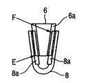
図8は、上記第1実施例にかかるテレスコ用ギアベース6とテレスコ用ギア部材8の変形例を示す断面図である。図8の変形例においては、テレスコ用ギアベース6の歯6aと、テレスコ用ギア部材8の歯8aの端部(点E,F)を、円弧や直線で輪郭付けしないことでシンプルな形状とし、それにより成形容易性を高めている。このような構成は、チルト用ギアベース7とチルト用ギア部材9についても同様に適用できる。
【0054】
図9は、上記第1実施例にかかるチルト用ギアベース7とチルト用ギア部材9の変形例を示す、図6と同様な断面図である。図9の変形例においては、チルト用ギア部材9は、歯9aの歯筋の先端形状を、チルト用ギアベース7の歯7aの先端形状の並びに平行に揃えて(即ち傾斜ν=0度)いる。このような構成は、テレスコ用ギアベース6とテレスコ用ギア部材8についても同様に適用できる。
【0055】
図10は、プレス成形による方法を用いて行うテレスコ用ギアベース6及びテレスコ用ギア部材8の製造方法を示すフローチャートである。図11は、転造成型による方法を用いて行うテレスコ用ギア部材8の加工状態を、製造工程順に示す図である。図12は、テレスコ用ギアベース6の加工状態を、製造工程順に示す図である。図13は、テレスコ用ギア部材8の加工を行うダイスを示す図であり、(a)はその上面図、(b)はその側面図である。
【0056】
図13(a)において、第1のダイスD1は円筒形状を有し、その中央に周方向に連続する突起D1aを形成し、その両側に周方向に並んだ歯D1bを形成している。一方、第2のダイスD2は円筒形状を有し、その中央に周方向に連続する突起D2aを形成しているが、その両側は円筒面となっている。図13(b)に示すように、逆方向に回転するダイスD1,D2の間に、板材Bを挿入することで、かかる板材Bに所定の加工がなされるようになっている。
【0057】
本実施の形態にかかるテレスコ用ギア部材8の製造方法について説明すると、まず図10のステップS101において、長板材を切断してブランク長さを決め、素材Bを形成する(上面図である図11(a)参照))。続くステップS102において、板材Bを、図13に示すダイスD1,D2の間をセンターをずらせて挿入することで、歯8a及び溝8c、8dを転造成形する(上面図である図11(b)及び側面図である図11(c)参照))。
【0058】
更に、ステップS103において、板材Bの歯8aが形成されていない端部側を折り曲げ(上面図である図11(d)及び側面図である図11(e)参照))、その後、溝8c、8dを中心に略U字形状に折り曲げることで、テレスコ用ギア部材8を得ている(上面図である図11(f)及び側面図である図11(g)参照))。
【0059】
一方、テレスコ用ギアベース6の加工には、第1のダイスD1を2つ用いる。本実施の形態にかかるテレスコ用ギアベース6の製造方法について説明すると、まず図10のステップS101において、長板材を切断してブランク長さを決め、素材Bを形成する(上面図である図12(a)参照))。続くステップS102において、板材Bを、図13に示すダイスD1,D2の間をセンターを合わせて挿入することで、歯6a及び溝6c、6cを転造成形する(上面図である図12(b)及び側面図である図12(c)参照))。
【0060】
更に、ステップS103において、板材Bの対向する溝6c、6cを切断することで、テレスコ用ギアベース6を得ている(上面図である図12(d)及び側面図である図12(e)参照))。かかる場合、テレスコ用ギアベース6は、一度の加工で2つ形成されることとなる。なお、チルト用ギアベース7とチルト用ギア部材9についても同様に適用できる。
【0061】
なお、以上の例では、ギアベース又はギア部材を板金プレスにより成形するものとしたが、圧粉体成形によるもの、射出成形によるもの、ダイカスト、チクソモールディング等鋳造による方法、塑性加工によるもの、または切削による成形等、成形方法は何れを適用しても良い。更に、操作レバー5で、同時にギア部材8,9を移動させているが、別個の操作レバーによって個々に移動させても良い。更に、楔型のギア部材の成形方法としては、コラムボディ本体、或いはチルトブラケット(車体に固定側)をダイカストにより製造する際に、ギアを一体成形する方法がある。
【0062】
図14は、変形例に係るステアリングコラム装置の斜視図である。本変形例においては、テレスコ用ギアベース6とテレスコ用ギア部材8とは、それぞれ片面にのみ歯6a、8aを形成して噛合させ、チルト用ギアベース7とチルト用ギア部材9とは、それぞれ片面にのみ歯7a、9aを形成して噛合させている。テレスコ用ギアベース6とテレスコ用ギア部材8、チルト用ギアベース7とチルト用ギア部材9のいずれか一方の組み合わせだけ、片面にのみ歯を形成することもできる。
【0063】
テレスコ用ギアベース6とテレスコ用ギア部材8、チルト用ギアベース7は、コラム本体1と操作レバー5と別体にしているが、それぞれ一体的に形成しても良い。以上の実施の形態に共通して、歯形については、モジュール0.5としたが、モジュールは大きくても小さくても問題ない。また、モジュールを非常に小さくしていった際に、歯面性状は、平面板の面性状に近づくが、平面性状であったとしても摩擦による位置保持効果が得られるため、本発明によるステアリングコラム装置の保持機能は作用する。
【0064】
図15は、変形例に係るステアリングコラム装置の斜視図である。本変形例では、テレスコ用ギアベース6は、コラム本体1と一体化されており、すなわちコラム本体1の両側面に歯6aが形成されている。一方、テレスコギヤ部材8は、一端を操作レバー5にボルト止めしてなる半円筒内周面を備えた板状を有し、歯6aに対応する内周面の位置に歯8aを形成している。操作レバー5を図15に示す位置から、反時計回りに回動させると、テレスコギヤ部材8がコラム本体1の下半部を包み込むようになり、それにより歯6a、8a同士が噛合することとなる。
【0065】
図16は、変形例に係るステアリングコラム装置のコラム本体を示す斜視図である。本変形例においては、コラム本体1を板金プレスにより形成している。コラム本体1は、成形容易性及び軽量化を確保するために平板から打ち抜き、丸め込むように折り曲げて成形している。本変形例では、テレスコ用ギアベース6は、コラム本体1の一方の側縁1bと一体化されており、即ち、板金プレス前に、平板の側縁1bの両側に歯6aが形成されているため、製造が容易である。
【0066】
操作レバー5は、軸線方向にのびる長孔1aに沿って移動可能なシャフト5aの周囲に駆動可能であり、その一部に形成された歯(不図示)が、歯6aと噛合するようになっている。テレスコ用ギアベース6は、コラム本体1の他方の側縁1cに設けても良いし、両方に設けることで、保持力を高く確保することができる。なお、テレスコ用ギアベース6を形成する側縁1b又は1cに関わらず、コラム本体1の両端は、内側に丸め込むようことで、ステアリングシャフト4を回転自在に支持する軸受(不図示)の保持部1d、1dを形成することができるので、低コストなステアリングコラム装置を提供できる。
【0067】
図17は、別な実施の形態にかかるテレスコ用ギアベース6とテレスコ用ギア部材8の断面図である。本実施の形態においては、テレスコ用ギアベース6が連結された操作レバー5は、シャフト5aに固定され、一体的に回転するようになっている。シャフト5aには回転カム5bが取り付けられ、一方、不図示のコラム本体に固定カム5cが取り付けられ、シャフト5aの回転に応じて、固定カム5cに対して回転カム5bが回転するようになっている。なおシャフト5aは、図17において、予圧により右方向に付勢されているものとする。回転カム5bと固定カム5cとで駆動手段を構成する。
【0068】
テレスコ用ギアベース6の両側のテーパ面の中心面(紙面に垂直に延在)をPL6とし、テレスコ用ギア部材8の両側のテーパ面の中心面(紙面に垂直に延在)をPL8とすると、図17(a)に示す離脱状態において、中心面PL6,PL8は、シャフト5aの軸線方向にずれている。
【0069】
ここで、図17(b)に示すように、操作レバー5を回動させると、シャフト5aと共に回動する回転カム5bのカム部が、固定カム5cのカム部に乗り上がり始め、シャフト5aは図で左方へと移動する。更に操作レバー5を回動させると、回転カム5bのカム部が、固定カム5cのカム部に完全に乗り上がるので、シャフト5aは図17(c)に示す位置へと移動する。かかる状態では、中心面PL6、PL8が互いに重なる位置となる。また更に操作レバー5を回動させることで、テレスコ用ギアベース6とテレスコ用ギア部材8同士が噛合することとなる(図5参照)。
【0070】
本実施の形態によれば、両部材6,8が離脱した状態で、テレスコ用ギアベース6の両側テーパ面の中心面PL6と、テレスコ用ギア部材8の両側テーパ面の中心面PL8とがズレており、操作レバー5を回動させることによって、テレスコ用ギアベース6とテレスコ用ギア部材8との噛み合い開始から噛み合い完了にわたって、カム駆動によって中心面PL6,PL8とを近づけるように駆動する。この構成により円滑なテレスコ用ギアベース6とテレスコ用ギア部材8の噛合を実現できる。以上、テレスコ用ギアベース6とテレスコ用ギア部材8について述べたが、チルト用ギアベース7とチルト用ギア部材9にも同様に適用できる。
【0071】
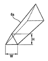
図18は、テレスコ用ギアベース6の歯6aの一つの斜視図である。長手方向に直交する断面が三角形状(二等辺三角形であれば好ましいが、それに限られない)の歯6aは、先細形状となっており、より具体的には、歯の断面積が歯筋の先端部分において小さくなっており(即ち歯の高さHと歯の幅Wの少なくとも一方が小さく)、歯の断面積が小さくなっていない部分から歯の断面積が小さくなる部分、そして、先端の細く尖った尖り部までが滑らかに形成されている。歯6aが、このような先細形状を有するので、テレスコ用ギア部材8の歯8aにスムーズに噛合することができる。テレスコ用ギア部材8の歯8aを同様に先細形状としても良い。又、このような構成は、チルト用ギアベース7とチルト用ギア部材9についても同様に適用できる。
(第2実施例)
【0072】
次に、本発明の第2の実施例について図19、20を用いて説明する。第2の実施例にかかるチルト・テレスコピック式のステアリングコラム装置は、衝突時に負荷される力により噛み合い率ηが増加するように、歯筋が傾斜していることを特徴とする。上述の実施例1と同様の第2の実施例の部材には同一の符号を付与し、その詳細な説明は省略する。
【0073】
図19は、通常時におけるテレスコ用ギアベース6及びテレスコ用ギア部材8を示す図であり、図20は、衝突時におけるテレスコ用ギアベース6及びテレスコ用ギア部材8を示す図である。
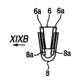
それぞれ図19A、図20Aは、ギアベース6とギア部材8を車体方向側方から見た図であり、図19B、図20Bは、夫々図19A、図20AのXIX B,XX B矢視図、図19C、図20Cは、夫々図19A、図20AのXIX C、XX C矢視図である。
【0074】
本実施の形態においては、ステアリングシャフト1(図1)の軸線に対して、歯6a、8aの歯筋の角度γ=85度としており、軸線に垂直な方向よりステアリングホイール(不図示)側に傾いている。ここで、通常時における歯6a、8aの噛み合い率η′とする(図19(c)参照)。このときの保持力をF2とする。
【0075】
例えば車両の二次衝突が生じ、運転者がステアリングホイールに衝突した場合を考える。この場合、テレスコ用ギアベース6及びテレスコ用ギア部材8は、ステアリングシャフト1の軸線方向に相対移動するような力Fcを受ける(図20(a)参照)。しかるに、本実施の形態によれば、歯6a、8aの歯筋の角度γ=85度で傾いているので、力Fcは、歯6a、8aの歯筋に沿った方向の成分Fxと、それに直交する方向の成分Fyとに分解される。
【0076】
力の成分Fxは、テレスコ用ギアベース6を、テレスコ用ギア部材8に向かって押圧する力であるので、図20A、20Bに示すように、テレスコ用ギアベース6は、テレスコ用ギア部材8内に押し込まれる。更に、歯6a、8aは、テレスコ用ギアベース6及びテレスコ用ギア部材8におけるテーパ面に形成されていることから、歯6a、8a同士が互いに向かって押圧される。このとき、その噛み合い率η”は、通常時の噛み合い率η′より大きくなる。ゆえに、衝突時の保持力F3は、通常時の保持力F2より高まる。力の成分Fxは、力Fcの大きさに比例して増大するので、衝撃力の強さに応じて保持力を高めることができる。即ち、本実施の形態によれば、歯数を少なく抑えても保持力を確保することができるので、軽量且つコンパクトでありながら、良好な操作フィーリングを確保できる。なお、γは90度以下になるように設定されていればよい。すなわち、歯筋は衝突力方向に対して角度が設けられていればよい。チルト用ギアベース7及びチルト用ギア部材9においても、同様に歯筋に角度を持たせることができる。
【0077】
また、テレスコ用ギアベース6とテレスコ用ギア部材8の歯筋は、直線であるが、操作レバー5の中心をした曲率半径R(図1)の円弧状に形成すると好ましい。テレスコ用ギア部材8は、操作レバー5に固定されるので、その歯8aの移動軸跡は円弧状となる。なお、テレスコ用ギアベース6とテレスコ用ギア部材8の円弧状に形成されている歯筋の微小要素を取り出したときに、歯筋の傾きが0〜90度の範囲に入っていれば、衝突時の入力によりギアの噛み合い率が増加する。また、歯筋は円弧状であるので、歯6a、8a同士が噛合する際に、操作フィーリングが向上する。
(第3実施例)
【0078】
上述の第2実施例と同様に、車両の衝突時にコラムに過大な力が作用すると、ギアが緩む虞がある。ギアの緩みが発生すると、ギアの噛合率が低下してギアが破損したり、ギアの噛合自体が逸脱する可能性がある。上記のギアの緩みを押えるためには、ステアリングコラム装置に剛性の高い部材を用いたり、ギアの緩みを押える特別な機構を用いるということも考えられるが、コストが増加したり、構造が複雑になるといった観点から望ましくない。
【0079】
そこで上記問題を解決すべく、以下に詳述するようにギアの形状と寸法を定めると、ギアの歯面に作用する摩擦力によりギアが緩むという問題が解消される。また、本発明の第3実施例によれば簡単で安価なステアリングコラム装置を提供することができる。
【0080】
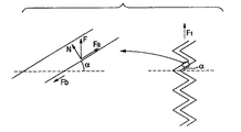
本発明の後述する第3実施例と比較するために、従来のステアリングコラム装置のギア構造として特開平9−221043号公報に示されるギア構造を図21,22に示す。
図21に示す従来のギア構造によれば、車両の衝突時にコラム101、レバーシャフト103、レバー104、レバー104に取り付けられたギア105には、矢印方向に移動させる衝突力が負荷される。この衝突力に対し、ブラケット102に取り付けられたギア106とギア105の噛合により、それら部材101,103,104,105の移動が抑止される。しかしながら、図22に示すように過大な衝突力F1が作用した場合には、ギア面に発生する摩擦力Fbよりも、摩擦面により衝突力が分解されて生じる分力Faが大きくなる。この結果、レバー104はギア105と共に、ギア106から離間するのでレバーのクランプ状態が開放される。つまり、ギアの噛合自体が逸脱し、クランプ状態が維持できなくなる。
【0081】
上記のクランプ機構の開放を防止するためには、摩擦力Fbを衝突力の分力Faよりも大きくなるように設定すればよい。例えば図22を参照して、ギアの頂角αを、歯面同士の摩擦角μよりも小さく設定することが考えられる。ここで、分力Faは頂角αを用いてFa=F1sinαと表され、一方、摩擦力Fbは頂角α、摩擦角μを用いて、Fb=F1cosα・tanμと表される。
摩擦力Fbを分力Faよりも大きく設定すると(Fb>Fa)、以下の式が得られる。
F1cosα・tanμ>F1sinα
tanμ>tanα
従って、μ>αという関係式が導出される。
【0082】
しかし、一般的にギアの半頂角は25度や30度に設定されているが、この角度よりも歯の頂角を小さく設定すると、歯元厚さが小さくなり歯の強度が十分に確保できず、また、歯の加工性が飛躍的に困難になる。よって上記のギアの頂角を摩擦角より小さく設定することは現実的な解決方法ではない。
【0083】
そこで、上記のクランプ機構の開放を防止するために以下に詳述するように、本発明の第3実施例として、歯面全体を歯の噛み合い方向からβ度傾斜させ、さらに歯筋方向を衝突力の作用する方向に対してγ度傾斜させることを考案した。
【0084】
以下に、本発明の第3の実施例について図23A〜図24を用いて詳細に説明する。本発明の第3実施例は、歯面全体をβ傾斜させ、歯筋方向と衝突力方向の成す角をγとした構成である。その他の上述の第1,2実施例と同様の第3実施例の部材には同一の符号を付与し、その詳細な説明は省略する。
【0085】
図23A〜23Eに示すように、以下の説明においては、各歯の半頂角をα、歯の噛合方向に対する歯面の傾斜角をβ、歯筋方向が衝突力方向となす角度をγと定義する。
【0086】
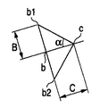
まず、歯筋の傾斜角γが90°である実施例を示す図23A〜23Eを用いて第3実施例を説明する。図23Aはギア部材・ギアベースを車体の軸方向から見た図である。図23Bは図23Aの側面から見た図である。図23Cは図23Aの要部拡大図、図23Dは図23Bの要部拡大図である。また、図23Eは図23CのXXIII E矢視図である。
【0087】
図23Aに示したように、実施例3によるギアベースとギア部材の歯面全体は、噛み合い面に対して角度βで傾斜している。ここで、噛み合い面とは、ギアベースとギア部材が噛み合ってから、その噛み合い率が増加するようにギア部材を移動させる際に、ギア部材の長軸が形成する軌跡に沿う面である。
【0088】
面Pを図23A、図23Bに示すように、噛み合い面に平行で、かつ、歯筋の一部を横切る面で定義する。歯筋の噛合は以下に詳述するように、この面Pに現れる線分上に発生する摩擦力より維持される。
この面Pが歯を横切る際に形成される三角形において、歯の頂点に相当する点をa1、歯筋の底に相当する2点を夫々b1,b2とする。また、線分b1−b2を通過して面Pに直交する面が歯筋の頂点と交わる点をa2とする。さらに、点a2を通過する面Pの法線上における面Pとの交点をbとする。
【0089】
ここで、半頂角αは図23Eに示すように角度b1・c・b2の1/2の角度であり、歯面の傾斜角βは図23Cに見られるように角度b・a1・a2で表される。
また、角度θを線分a1−b1と衝突方向の成す角で定義する。つまり、角度θは、摩擦力が作用する方向と衝突力方向がなす角度ということができる。この角度θは後述するようにギアの抜け難さを定義するパラメータである。
【0090】
点bを通過する線分a1−a2の法線が線分a1−a2と交わる点を点cと定義する。更に、以下の説明のために点a1とbで定義される辺を辺A、点b1と点bで定義される辺を辺B、点bと点cで定義される辺を辺Cと表現する。
図23Dに見られるように、角度αはtanα=B/C、角度βはsinβ=C/Aで表される。したがって、B=C・tanα、A=C/sinβとなる。また、角度θはtanθ=A/B、であるから、θをα,βを用いて表すと、以下の式が得られる。
tanθ=(C/sinβ)/(C・tanα)=1/tanα・sinβ
よって、1/tanθ=tanα・sinβとなり、これを変形して、tan(90°−θ)=tanα・sinβより、θについて、以下の関係式が得られる。
90°−θ=tan−1(tanα・sinβ)
【0091】
ここで、歯が噛み合う方向の両歯面間の摩擦角をμとすると、歯の傾斜角度を表す90°−θが歯面の摩擦角よりも小さければ、衝突力が作用しても、歯面間の摩擦力により歯の噛み合いが緩むことがなく、また噛み合い率が落ちることを防止でき、歯とレバーとが噛み合い状態から離脱することを防止できる。すなわち、上記の条件は以下の式で表される。
μ>90°−θ
θを上記の関係式よりα、βで表現すると以下の式が得られる。
μ>90°−θ=tan−1(tanα・sinβ)
【0092】
次に、歯筋が衝突力の方向となす角度がγである場合を図24を用いて説明する。図24は図23Dに対応する図である。図24における歯筋は、図23Dにおける歯筋から衝突時に歯が噛み合う方向に(90°−γ)度傾斜したので、摩擦力の作用する方向である線分a1−b1が衝突方向と成す角はθ+(90°−γ)度となる。この時、上記と同様にして
90°−{θ+(90°−γ)}=tan−1(tanα・sinβ)−(90°−γ)と
μ>90°−{θ+(90°−γ)より、以下の条件式が導出される。
μ>tan−1(tanα・sinβ)−(90°−γ)(条件式)
上記の条件式を満たすようにα、β、γ、μを設定すれば、歯の噛合が緩むことなく、また、歯とレバーが噛合状態から離脱することを防止できる。
なお、衝突力が図24,25において上から下に作用として説明してきたが、衝突力が下から上に作用する場合(すなわち、ギアがはずれる方向に衝突力が作用した場合)においても上述の条件式が適用できる。
【0093】
*第3実施例の適用例
上述の本発明の第3実施例の具体例を以下に説明する。表1は第3実施例において、α、β、γを歯の噛合が維持される例と、維持されない例を示す。
【表1】
【0094】
第3実施例によれば、第2実施例で説明されたように歯筋方向をγ度傾斜させて車両衝突時の噛合率ηを増加させて外れにくく構成し、更に歯面全体の傾斜角度β度を規定することにより、更に抜け難い構成としたステアリングコラム装置が提供される。
このように、θが摩擦角を越えないように三次元的にある一定の関係式により歯面角度α、β、γ、θを設定することで、歯筋方向の噛み合い長さの減少と、噛み合い率の低下を防止でき、ひいては過大な荷重が作用した際にも噛み合う歯が外れないという効果を奏する。
【0095】
(第4実施例)
図25,26を用いて本発明の第4実施例を説明する。
図25に示すようにギアAとギアBの一組の歯面によってギアの噛合が構成されている場合は、ギアAとギアBとが衝突力方向、あるいは、噛合方向の法線方向に相対変位しやすい。すなわち、ギアの噛合率が落ちて最終的にはギアの噛合が抜けてしまう。これを防ぐために、ギアAとギアBの相対変位を生じさせないために、ステアリングコラム装置の各部材の剛性を高める必要がある。しかし、このような要求に応えるのは不可能に近い。
【0096】
そこで、本発明の実施例4の図26に示すように、二組のギアを所定角度を有して対向させてくさび形を形成するようにギアを配置させると、ギアAとギアBの両面で、衝突力方向と噛合方向の法線方向に作用する力を相殺できる。よって、ギアAとギアBとの衝突力方向と噛合方向の法線方向に沿ったギアA,B間の相対変位を防止することができる。
【0097】
上述の第3、第4実施例に説明されたように、θが摩擦角を越えないように三次元的にある一定の関係式により歯面角度α、β、γ、θを設定することで、歯筋方向の噛み合い長さの減少と、噛み合い率の低下を防止でき、ひいては過大な荷重が作用した際にも噛み合う歯が外れないという効果を奏する。
【0098】
以上、実施の形態を参照して本発明を詳細に説明してきたが、本発明は上記実施の形態に限定して解釈されるべきでなく、その趣旨を損ねない範囲で適宜変更、改良可能であることはもちろんである。例えば、ギアベースとギア部材とは逆の構成・形状であってもよく、組み合わせは任意である。また、上述の第1実施例から第4実施例とを組み合わせてステアリングコラム装置を構成してもよい。
【0099】
本発明を詳細にまた特定の実施態様を参照して説明したが、本発明の精神と範囲を逸脱することなく様々な変更や修正を加えることができることは当業者にとって明らかである。
本出願は、2005年5月6日出願の日本特許出願(特願2005−134974)、2005年5月17日出願の日本特許出願(特願2005−143434)、2006年3月16日出願の日本特許出願(特願2006−72616)、に基づくものであり、その内容はここに参照として取り込まれる。
【産業上の利用可能性】
【0100】
本発明のステアリングコラム装置によれば、前記第1の歯と前記第2の歯とは、それぞれの歯筋に対して法線方向及び接線方向(接線に平行な方向を含む)以外の方向に沿って接近させて噛合させるようになっているので、前記第1の歯と前記第2の歯の噛合不良を抑制できる。従って、多板の摩擦プレートを用いたときのように操作フィーリングが悪くなることが回避され、更に前記第1の歯と前記第2の歯が噛合した後は、大きな保持力を発揮できる。特に、前記第1の歯と前記第2の歯の最初の噛合が生じたときから、両者を歯筋方向に摺動させつつ噛み合い率を高めるようにすると、スムーズな噛合を行える。【Technical field】
[0001]
The present invention relates to a steering column device that supports a steering shaft so as to be adjustable with respect to at least one of a tilt direction and a telescopic direction.
[Background]
[0002]
The steering column device is an important safety and security component of the vehicle, and it is very important how to control the behavior at the time of the collision in order to ensure the safety of the passenger at the time of the collision. Normally, the steering column device itself is provided with an impact energy absorbing mechanism, and also plays an important role as a support member for an air bag accommodated in the steering wheel.
[0003]
On the other hand, in order to optimize the driver's driving posture, a general steering column device can adjust the tilt angle of the steering wheel according to the driver's physique and driving posture, and adjust the axial direction position of the steering wheel It can be done. Therefore, the steering column device needs to have a conflicting function that the position and posture of the column body (that is, the steering wheel) must be easily adjusted, and that a predetermined position and posture must be secured in the event of a collision. Become. In order to make such contradictory functions compatible, the conventional steering column device has been devised in various ways. However, further improvement is demanded due to the increasing demand for user operability.
[0004]
Here,
[Patent Document 1]
JP 10-35511 A
[Patent Document 2]
German Patent No. 10212263
[Patent Document 3]
US Patent Publication No. 2005 / 0016315A1
DISCLOSURE OF THE INVENTION
[Problems to be solved by the invention]
[0005]
However, the mechanism that superimposes the multi-plate friction plates has a complicated structure, and the vibration of rubbing the multi-plate friction plates during the tilt / telescopic adjustment is easily transmitted to the operator, and there is a problem that the operation feeling is poor. . Moreover, since the number of parts increases, there exists a problem that an assembly man-hour increases.
[0006]
On the other hand, in Patent Document 2, during tilt / telescopic adjustment, the gears engaged with each other are disengaged, and after the adjustment, the gears are engaged with each other so that the position of the column body can be reliably held. A column device is disclosed. However, in the case of a mechanism that holds the position of the column main body by meshing the gear as shown in Patent Document 2, when the gear is meshed after adjustment, the gear crests naturally contact each other so that the meshing is inherently poor. May occur. In Patent Document 2, attempts have been made to suppress this, but it is not always sufficient.
[0007]
Further, in
[0008]
Further, in a steering column device of a type that meshes teeth, when force is applied to the steering shaft at the time of collision, in order to increase the holding force that can resist this, it is considered to increase the number of meshed teeth. It is done. However, when the number of meshing teeth is increased, there is a problem that a meshing failure after position adjustment is likely to occur, and an installation space is required correspondingly.
[Means for Solving the Problems]
[0009]
The present invention has been made in view of the problems of the prior art, and an object of the present invention is to provide a steering column apparatus that can increase the holding force and is excellent in operation feeling while being lightweight and compact. And
[0010]
According to a first aspect of the present invention, in the steering column device that supports the steering shaft so that the position of the steering shaft can be adjusted with respect to at least one of the tilt direction and the telescopic direction.
A first tooth fixed to the vehicle body side;
A column body that rotatably supports the steering shaft;
Second teeth that move integrally with the column body;
The first teeth and the second teeth mesh with each other to position the column body with respect to the vehicle body;
The first teeth and the second teeth are separated from each other, and the column body is in a state in which the position of the column body can be adjusted with respect to the vehicle body,
While the engagement between the first teeth and the second teeth is completed immediately before the engagement, the approaching direction of the second teeth with respect to the first teeth makes 0 degrees with respect to each tooth trace direction. The first teeth and the second teeth are brought close to each other so as to be set to be greater than 90 degrees and less than 90 degrees.And
One of the first teeth and the second teeth is provided on a pair of opposed first inclined surfaces,
The other of the first teeth and the second teeth is formed on a pair of second inclined surfaces that respectively face the pair of first inclined surfaces.The
[0012]
First of the present invention2According to the point of view1Steering column device from the viewpoint of
In a state where the first and second teeth are separated from each other, a second inclined surface defined between the center surface of the first inclined surface defined between the pair of first inclined surfaces and the pair of second inclined surfaces. The center plane of the surface is displaced from each other,
Drive means for driving the center surface of the first inclined surface and the center surface of the second inclined surface closer to each other before engaging the first tooth with the second tooth.
[0013]
First of the present invention3According to the point of viewOr 2The steering column device according to the above aspect has an arcuate locus together with the lever by rotationally moving a lever connected to one of the first teeth and the second teeth. The moving one tooth may be engaged with the other tooth of the first tooth and the second tooth.
[0014]
First of the present invention4According to the point of viewOr 2In the steering column device according to the above aspect, at least one of the first teeth and the second teeth may be formed such that a cross-sectional area of the teeth decreases toward the tip.
[0015]
First of the present invention5According to this aspect, the steering column device according to the first aspect further includes
A bracket fixed to the vehicle body,
A lever that is swingably attached to the bracket and that moves with the column body in a tilting manner;
The first tooth is provided on the bracket fixed to the vehicle body side,
The second tooth may be provided on the lever that tilts together with the column body.
[0016]
First of the present invention6According to the above aspect, the steering column device according to the first aspect is
It has a lever swingably supported by a bracket fixed to the vehicle body side,
As the lever rotates, telescopic movement of the column body relative to the lever is allowed,
The first tooth is provided on a lever supported on the vehicle body side,
The second tooth may be provided on the column main body that telescopically moves.
[0017]
First of the present invention7According to the point of view1Steering column device from the viewpoint of
The pair of first inclined surfaces face each other at a predetermined angle to form a wedge shape,
The pair of second inclined surfaces may also face each other at a predetermined angle to form a wedge shape.
[0018]
First of the present invention8According to an aspect of the present invention, there is provided a steering column device according to the first aspect,
The first teeth and the second teeth may have tooth traces inclined in a direction in which a meshing rate increases when a force is applied to the steering shaft.
[0019]
First of the present invention9According to the point of view8Steering column device from the viewpoint of
The friction angle between the first tooth and the second tooth is μ,
A half apex angle of the first tooth and the second tooth is α,
An angle formed by the tooth surface of the first tooth and the tooth surface of the second tooth with respect to the meshing surface is β,
When the angle between the direction of the first tooth and the second tooth trace and the direction of the force is defined as γ,
The tooth surface is arranged so as to satisfy the following conditional expression.
μ> tan-1(tanα ・ sinβ) − (90 ° −γ) (Conditional expression)
Here, the meshing surface is a locus formed by the long axis of one tooth when the first tooth and the second tooth are meshed and then one of the teeth is moved so as to increase the meshing rate. It is a surface along.
[0020]
First of the present invention10In the steering column device that supports the steering shaft so that the position of the steering shaft can be adjusted with respect to at least one of the tilt direction and the telescopic direction.
A first tooth fixed to the vehicle body side;
A column body that rotatably supports the steering shaft;
Second teeth that move integrally with the column body;
The first teeth and the second teeth mesh with each other to position the column body with respect to the vehicle body;
The first teeth and the second teeth are separated from each other, and the column body is in a state in which the position of the column body can be adjusted with respect to the vehicle body,
The first teeth and the second teeth are such that, when a force is applied to the steering shaft, the tooth traces are inclined in a direction in which the engagement rate increases.And
One of the first teeth and the second teeth is provided on a pair of opposed first inclined surfaces,
The other of the first teeth and the second teeth is formed on a pair of second inclined surfaces that respectively face the pair of first inclined surfaces..
[0022]
First of the present invention11According to the point of view10Steering column device from the viewpoint of
The pair of first inclined surfaces face each other at a predetermined angle to form a wedge shape,
The pair of second inclined surfaces may also face each other with a predetermined angle to form a wedge shape.
[0023]
First of the present invention12According to the point of view10Steering column device from the viewpoint of
The friction angle between the first tooth and the second tooth is μ,
A half apex angle of the first tooth and the second tooth is α,
An angle formed by the tooth surface of the first tooth and the tooth surface of the second tooth with respect to the meshing surface is β,
When the angle between the direction of the first tooth and the second tooth trace and the direction of the force is defined as γ,
The tooth surface may be arranged so as to satisfy the following conditional expression.
μ> tan-1(tanα ・ sinβ) − (90 ° −γ) (Conditional expression)
【The invention's effect】
[0024]
When gear-shaped parts having a plurality of straight teeth are meshed, the following two examples are usually considered. As a first example, the teeth are engaged with each other in the normal direction with respect to the tooth traces and then moved in parallel. As a second example, facing teeth move parallel to the tangential direction of the tooth trace and mesh. In either case, the tooth tips of the gears that mesh with each other or the tips of the tooth traces hit each other, and there is a high possibility that poor meshing will occur. Here, the “normal direction of the tooth trace” refers to a normal extending from above the tooth trace with respect to a virtual plane including a plurality of tooth traces in the same gear part.
[0025]
On the other hand, according to the steering column device of the present invention, the first tooth and the second tooth are in the normal direction and the tangential direction (including directions parallel to the tangent line) with respect to the respective tooth traces. Since it is made to approach and mesh | engage along directions other than, the meshing failure of a said 1st tooth | gear and a said 2nd tooth | gear can be suppressed. Therefore, it is avoided that the operation feeling is deteriorated as when a multi-plate friction plate is used, and a large holding force can be exhibited after the first teeth and the second teeth are engaged. In particular, it is preferable to increase the meshing rate while sliding both of the first teeth and the second teeth in the tooth trace direction after the first meshing of the first teeth and the second teeth. In the present specification, the “telescopic direction” refers to the axial direction of the steering shaft, and the “tilt direction” refers to the direction (particularly the vertical direction) intersecting with it.
[0026]
Further, when the first teeth and the second teeth are formed on both surfaces of the tapered surfaces facing each other, a stronger holding force can be exerted by meshing of the teeth on both surfaces.
[0027]
Further, in the disengaged state, the center surface of the tapered surface of the first tooth and the center surface of the tapered surface of the second tooth are misaligned, and at the time of meshing, the center of the tapered surface of the first tooth Smoother meshing can be realized by having driving means for driving the surface and the center surface of the tapered surface of the second tooth closer.
[0028]
By rotating the lever connected to one of the first teeth and the second teeth, the one tooth that moves in an arc with the lever is the first tooth and the second tooth. When the second tooth is engaged with the other tooth, a reliable operation can be realized with a simple configuration.
[0029]
It is preferable that at least one of the first tooth and the second tooth has a smaller cross-sectional area toward the tip, because it can easily mesh with the second tooth.
[0030]
According to the steering column device of the present invention, when the force is applied to the steering shaft at the time of collision, the first teeth and the second teeth are inclined in a direction in which the meshing rate increases. Therefore, the greater the impact force applied to the steering shaft, the higher the meshing rate and the holding force can be improved. Further, since the holding force can be secured even if the number of teeth is reduced, there is an advantage that a good operation feeling can be secured while being lightweight and compact.
[0031]
Further, when one of the first teeth and the second teeth is formed on the tapered surfaces facing each other and the other is formed on the back-to-back tapered surfaces, the engagement rate can be increased at the time of collision.
[0032]
Furthermore, by setting the tooth surface angles α, β, γ, θ according to a certain three-dimensional relational expression so that θ does not exceed the friction angle, the meshing length decreases and the meshing rate decreases. As a result, it is possible to prevent the teeth engaged with each other from being removed even when an excessive load is applied.
[Brief description of the drawings]
[0033]
FIG. 1 is a perspective view of a steering column device according to an embodiment.
FIG. 2 is a perspective view of a steering column device according to a modification.
FIG. 3 is a perspective view of the
FIG. 4 is a cross-sectional view of the
FIGS. 5A to 5E are sectional views of a
6 is a perspective view showing the relationship between the
FIG. 7 is a perspective view showing a modification of the
FIG. 8 is a cross-sectional view showing a modification of the
9 is a cross-sectional view similar to FIG. 6, showing a modification of the
FIG. 10 is a flowchart showing a method for manufacturing the
FIGS. 11A to 11G are views showing the processing states of the
FIGS. 12A to 12E are views showing the processing states of the
FIGS. 13A and 13B are views showing a die for processing the
FIG. 14 is a perspective view of a steering column device according to a modification.
FIG. 15 is a perspective view of a steering column device according to a modification.
FIG. 16 is a perspective view of a column body of a steering column device according to a modification.
17A to 17C are cross-sectional views of a
18 is a perspective view of one of the
FIG. 19A is a diagram showing a
19B is a view on arrow XIX B of FIG. 19A.
FIG. 19C is a view on arrow XIX C of FIG. 19A.
20A is a diagram showing a
20B is a view on arrow XX B in FIG. 20A.
FIG. 20C is a view taken along arrow XX C in FIG. 20A.
FIG. 21 is a conventional steering for explaining a third embodiment;columnIt is a figure which shows an apparatus.
FIG. 22 is a view showing a conventional gear mechanism for explaining a third embodiment.
FIG. 23A is a side view of the gear member when the tooth surface inclination angle is set to β and the tooth muscle inclination angle is set to 0 degree in the third embodiment;
23B is a front view of the gear member as viewed in FIG. 23A from the left direction of FIG. 23A.
FIG. 23C is an enlarged view of a main part of FIG. 23A.
FIG. 23D is an enlarged view of a main part of FIG. 23B.
FIG. 23E is a view on arrow XXIII E in FIG. 23C.
FIG. 24C shows the gear member when the inclination angle of the tooth trace is inclined by γ degrees in FIG. 23C.
FIG. 25 is a comparative view showing a case where the meshing of gears is constituted by a set of tooth surfaces for explaining the fourth embodiment.
FIG. 26 is a perspective view showing a gear member of a fourth embodiment.
BEST MODE FOR CARRYING OUT THE INVENTION
[0034]
Hereinafter, tilt and telescopic steering according to embodiments of the present inventioncolumnThe apparatus will be described with reference to the drawings.
(First embodiment)
[0035]
1 and 2 are perspective views of a steering column device according to a first embodiment of the present invention, in which FIG. 1 shows a locked state and FIG. 2 shows a released state.
[0036]
The cylindrical column
[0037]
A plate-shaped
[0038]
An
[0039]
A cam type
[0040]
When the operating
[0041]
FIG. 3 is a perspective view of the
[0042]
In the present embodiment, the taper angle κ of the tapered surfaces of the
[0043]
Further, the tooth traces of the
[0044]
FIG. 5 is a cross-sectional view of the
[0045]
From this point, when the
[0046]
If the
[0047]
In the case of the first embodiment, the
[0048]
The meshing operation of the
[0049]
FIG. 6 is a perspective view showing the relationship between the
[0050]
At the time of meshing, the
[0051]
In the first embodiment, the inclination angle ν is set to 5 degrees. However, the gear engagement start is not limited to the angle and shape since it is only necessary to start the meshing from one tooth. Such a configuration can be similarly applied to the
[0052]
FIG. 7 is a perspective view showing a modification of the
[0053]
FIG. 8 is a cross-sectional view showing a modification of the
[0054]
FIG. 9 is a cross-sectional view similar to FIG. 6, showing a modification of the
[0055]
FIG. 10 is a flowchart showing a method for manufacturing the
[0056]
In FIG. 13A, the first die D1 has a cylindrical shape, a protrusion D1a continuous in the circumferential direction is formed at the center thereof, and teeth D1b aligned in the circumferential direction are formed on both sides thereof. On the other hand, the second die D2 has a cylindrical shape, and a protrusion D2a continuous in the circumferential direction is formed at the center thereof, but both sides thereof are cylindrical surfaces. As shown in FIG. 13B, a predetermined processing is performed on the plate material B by inserting the plate material B between the dies D1 and D2 rotating in the opposite directions.
[0057]
The manufacturing method of the
[0058]
Further, in step S103, the end side of the plate material B where the
[0059]
On the other hand, two first dies D1 are used to process the
[0060]
Further, in step S103, the
[0061]
In the above example, the gear base or the gear member is formed by sheet metal press, but by compact molding, by injection molding, die casting, thixo molding or the like, by plastic working, or Any molding method such as molding by cutting may be applied. Furthermore, although the
[0062]
FIG. 14 is a perspective view of a steering column device according to a modification. In this modification, the
[0063]
The
[0064]
FIG. 15 is a perspective view of a steering column device according to a modification. In this modification, the
[0065]
FIG. 16 is a perspective view showing a column main body of a steering column device according to a modification. In this modification, the
[0066]
The
[0067]
FIG. 17 is a cross-sectional view of a
[0068]
When the center surface of taper surfaces on both sides of the telescopic gear base 6 (extending perpendicular to the paper surface) is PL6, and the center surfaces of taper surfaces on both sides of the telescopic gear member 8 (extending perpendicular to the paper surface) are PL8. In the detached state shown in FIG. 17A, the center planes PL6 and PL8 are displaced in the axial direction of the
[0069]
Here, as shown in FIG. 17B, when the operating
[0070]
According to the present embodiment, in a state in which both
[0071]
FIG. 18 is a perspective view of one of the
(Second embodiment)
[0072]
Next, a second embodiment of the present invention will be described with reference to FIGS. Tilt and telescopic steering according to the second embodimentcolumnThe apparatus is characterized in that the tooth traces are inclined so that the engagement rate η increases due to the force applied at the time of collision. The same reference numerals are given to members of the second embodiment similar to the above-described first embodiment, and detailed description thereof is omitted.
[0073]
FIG. 19 is a diagram illustrating the
19A and 20A are views of the
[0074]
In the present embodiment, the angle γ of the
[0075]
For example, consider a case where a secondary collision of the vehicle occurs and the driver collides with the steering wheel. In this case, the
[0076]
Since the force component Fx is a force that presses the
[0077]
Further, although the tooth traces of the
(Third embodiment)
[0078]
Similar to the second embodiment described above, if an excessive force is applied to the column during a vehicle collision, the gear may be loosened. If the gear is loosened, the gear meshing rate may be reduced and the gear may be damaged, or the gear meshing itself may deviate. In order to suppress the looseness of the above gear, the steeringcolumnAlthough it is conceivable to use a highly rigid member for the apparatus or a special mechanism for suppressing the loosening of the gear, it is not desirable from the viewpoint of increasing the cost or complicating the structure.
[0079]
Therefore, in order to solve the above problem, if the shape and dimensions of the gear are determined as described in detail below, the problem that the gear loosens due to the frictional force acting on the tooth surface of the gear is solved. Also, according to the third embodiment of the present invention, simple and inexpensive steeringcolumnAn apparatus can be provided.
[0080]
In order to compare with a third embodiment of the present invention, which will be described later, the conventional steeringcolumnThe gear structure disclosed in Japanese Patent Application Laid-Open No. 9-222103 is shown in FIGS.
According to the conventional gear structure shown in FIG. 21, the
[0081]
In order to prevent the opening of the clamp mechanism, the frictional force Fb may be set to be larger than the component force Fa of the collision force. For example, referring to FIG. 22, it is conceivable to set the apex angle α of the gear smaller than the friction angle μ between the tooth surfaces. Here, the component force Fa is expressed as Fa = F using the apex angle α.1On the other hand, the frictional force Fb is expressed as Fb = F using the apex angle α and the friction angle μ.1It is expressed as cos α · tan μ.
When the frictional force Fb is set larger than the component force Fa (Fb> Fa), the following equation is obtained.
F1cos α tan μ> F1sinα
tanμ> tanα
Therefore, a relational expression of μ> α is derived.
[0082]
However, in general, the half apex angle of the gear is set to 25 degrees or 30 degrees. However, if the apex angle of the tooth is set smaller than this angle, the tooth root thickness is reduced and the tooth strength is sufficiently secured. In addition, the processability of the teeth becomes extremely difficult. Therefore, setting the apex angle of the gear smaller than the friction angle is not a practical solution.
[0083]
Therefore, as described in detail below in order to prevent the opening of the clamping mechanism, as a third embodiment of the present invention, the entire tooth surface is inclined by β degrees from the meshing direction of the teeth, and further the tooth trace direction collides. It was devised to incline γ degrees with respect to the direction in which the force acts.
[0084]
Below, the 3rd Example of this invention is described in detail using FIG. 23A-FIG. In the third embodiment of the present invention, the entire tooth surface is inclined by β, and the angle formed by the tooth trace direction and the collision force direction is γ. The other members of the third embodiment similar to those of the first and second embodiments described above are given the same reference numerals, and detailed descriptions thereof are omitted.
[0085]
As shown in FIGS. 23A to 23E, in the following description, the half apex angle of each tooth is α, the inclination angle of the tooth surface with respect to the meshing direction of the tooth is β, and the angle between the tooth trace direction and the collision force direction is γ. Define.
[0086]
First, a third embodiment will be described with reference to FIGS. 23A to 23E showing an embodiment in which the inclination angle γ of the tooth trace is 90 °. FIG. 23A is a view of the gear member / gear base viewed from the axial direction of the vehicle body. FIG. 23B is a view from the side of FIG. 23A. 23C is an enlarged view of a main part of FIG. 23A, and FIG. 23D is an enlarged view of a main part of FIG. 23B. FIG. 23E is a view taken along arrow XXIII E in FIG. 23C.
[0087]
As shown in FIG. 23A, the entire tooth base of the gear base and the gear member according to the third embodiment is inclined at an angle β with respect to the meshing surface. Here, the meshing surface is a surface along a locus formed by the long axis of the gear member when the gear member is moved so that the meshing rate increases after the gear base and the gear member are meshed.
[0088]
As shown in FIGS. 23A and 23B, the surface P is defined by a surface parallel to the meshing surface and crossing a part of the tooth trace. As described in detail below, the meshing of the tooth trace is maintained by the frictional force generated on the line segment appearing on the surface P.
In the triangle formed when the surface P crosses the tooth, a point corresponding to the apex of the tooth is a1, and two points corresponding to the bottom of the tooth trace are b1 and b2, respectively. A point where a surface passing through the line segment b1-b2 and orthogonal to the surface P intersects with the apex of the tooth trace is defined as a2. Further, an intersection point with the surface P on the normal line of the surface P passing through the point a2 is defined as b.
[0089]
Here, as shown in FIG. 23E, the half apex angle α is ½ of the angle b1, c, b2, and the inclination angle β of the tooth surface is the angle b, a1, a2, as shown in FIG. 23C. expressed.
Further, the angle θ is defined as an angle formed by the line segment a1-b1 and the collision direction. That is, the angle θ can be said to be an angle formed by the direction in which the frictional force acts and the collision force direction. This angle θ is a parameter that defines the difficulty of gear removal, as will be described later.
[0090]
A point where the normal of the line segment a1-a2 passing through the point b intersects with the line segment a1-a2 is defined as a point c. Further, for the following explanation, the side defined by the points a1 and b is represented as side A, the side defined by the points b1 and b is represented by side B, and the side defined by the points b and c is represented by side C. To do.
As seen in FIG. 23D, the angle α is represented by tan α = B / C, and the angle β is represented by sin β = C / A. Therefore, B = C · tan α and A = C / sin β. Further, since the angle θ is tan θ = A / B, the following formula is obtained when θ is expressed using α and β.
tan θ = (C / sin β) / (C · tan α) = 1 / tan α · sin β
Therefore, 1 / tan θ = tan α · sin β is obtained, and the following relational expression is obtained for θ from tan (90 ° −θ) = tan α · sin β.
90 ° -θ = tan-1(Tan α ・ sin β)
[0091]
Here, when the friction angle between both tooth surfaces in the direction in which the teeth mesh is μ, if the 90 ° −θ representing the inclination angle of the teeth is smaller than the friction angle of the tooth surfaces, even if the collision force acts, the teeth It is possible to prevent the meshing of the teeth from loosening due to the frictional force between the surfaces, to prevent the meshing rate from falling, and to prevent the teeth and the lever from leaving the meshing state. That is, the above condition is expressed by the following formula.
μ> 90 ° -θ
When θ is expressed by α and β from the above relational expression, the following expression is obtained.
μ> 90 ° −θ = tan-1(Tan α ・ sin β)
[0092]
Next, the case where the angle between the tooth trace and the direction of the collision force is γ will be described with reference to FIG. FIG. 24 is a diagram corresponding to FIG. 23D. The tooth traces in FIG. 24 are inclined (90 ° −γ) degrees in the direction in which the teeth mesh with each other at the time of collision from the tooth traces in FIG. 23D. Is θ + (90 ° −γ) degrees. At this time, as above
90 ° − {θ + (90 ° −γ)} = tan-1(Tan α · sin β) − (90 ° −γ) and
From μ> 90 ° − {θ + (90 ° −γ), the following conditional expression is derived.
μ> tan-1(Tan α · sin β) − (90 ° −γ) (conditional expression)
If α, β, γ, and μ are set so as to satisfy the above conditional expression, the meshing of the teeth can be prevented and the teeth and the lever can be prevented from being separated from the meshing state.
24 and 25, the collision force has been described as acting from top to bottom. However, even when the collision force acts from bottom to top (that is, when the collision force acts in the direction in which the gear is disengaged), Conditional expressions can be applied.
[0093]
* Application example of the third embodiment
A specific example of the third embodiment of the present invention will be described below. Table 1 shows an example in which the meshing of teeth is maintained with respect to α, β, and γ, and an example in which α is not maintained in the third embodiment.
[Table 1]
[0094]
According to the third embodiment, as described in the second embodiment, the tooth trace direction is inclined by γ degrees to increase the meshing rate η at the time of a vehicle collision so that it is difficult to come off. Further, the inclination angle of the entire tooth surface Steering with a configuration that is more difficult to escape by specifying β degreescolumnAn apparatus is provided.
In this way, by setting the tooth surface angles α, β, γ, θ by a certain three-dimensional relational expression so that θ does not exceed the friction angle, a reduction in the meshing length in the tooth trace direction, The reduction of the meshing rate can be prevented, and as a result, there is an effect that the meshing teeth are not detached even when an excessive load is applied.
[0095]
(Fourth embodiment)
A fourth embodiment of the present invention will be described with reference to FIGS.
As shown in FIG. 25, when gear meshing is constituted by a pair of tooth surfaces of gear A and gear B, gear A and gear B are relative to each other in the collision force direction or the normal direction of the meshing direction. Easy to displace. That is, the gear meshing rate drops and eventually the gear meshing is lost. In order to prevent this, the relative displacement between the gear A and the gear B does not occur.columnIt is necessary to increase the rigidity of each member of the apparatus. However, it is almost impossible to meet such demands.
[0096]
Therefore, as shown in FIG. 26 of the fourth embodiment of the present invention, when the gears are arranged so as to form a wedge shape by making two sets of gears face each other with a predetermined angle, both surfaces of the gear A and the gear B are arranged. Thus, the forces acting in the normal direction of the collision force direction and the meshing direction can be offset. Therefore, the relative displacement between the gears A and B along the normal direction of the collision force direction and the meshing direction between the gear A and the gear B can be prevented.
[0097]
As described in the third and fourth embodiments, the tooth surface angles α, β, γ, θ are set by a certain three-dimensional relational expression so that θ does not exceed the friction angle. Thus, it is possible to prevent the meshing length in the tooth trace direction from decreasing and the meshing rate from decreasing, and the meshing teeth do not come off even when an excessive load is applied.
[0098]
As described above, the present invention has been described in detail with reference to the embodiments. However, the present invention should not be construed as being limited to the above-described embodiments, and can be appropriately changed and improved without departing from the spirit thereof. Of course there is. For example, the gear base and the gear member may have opposite configurations and shapes, and the combination is arbitrary. Further, the steering system is combined with the first to fourth embodiments described above.columnAn apparatus may be configured.
[0099]
Although the present invention has been described in detail and with reference to specific embodiments, it will be apparent to those skilled in the art that various changes and modifications can be made without departing from the spirit and scope of the invention.
This application is a Japanese patent application filed on May 6, 2005 (Japanese Patent Application No. 2005-134974), a Japanese patent application filed on May 17, 2005 (Japanese Patent Application No. 2005-143434), and an application filed on March 16, 2006. This is based on a Japanese patent application (Japanese Patent Application No. 2006-72616), the contents of which are incorporated herein by reference.
[Industrial applicability]
[0100]
According to the steering column device of the present invention, the first teeth and the second teeth are in directions other than the normal direction and the tangential direction (including a direction parallel to the tangent line) with respect to the respective tooth traces. Since it is made to approach along and it meshes | engages, the meshing failure of a said 1st tooth | gear and a said 2nd tooth | gear can be suppressed. Therefore, it is avoided that the operation feeling is deteriorated as when a multi-plate friction plate is used, and a large holding force can be exhibited after the first teeth and the second teeth are engaged. In particular, since the first meshing between the first tooth and the second tooth occurs, the meshing rate can be increased by sliding both in the tooth trace direction and increasing the meshing rate.
Claims (12)
車体側に固定された第1の歯と、
ステアリングシャフトを回転自在に支持するコラム本体と、
前記コラム本体と一体的に移動する第2の歯とを有し、
前記第1の歯と前記第2の歯とが、互いに噛合して、前記コラム本体を前記車体に対して位置決めし、
前記第1の歯と前記第2の歯とが、互いに離間して、前記コラム本体を前記車体に対して位置調整可能な状態とし、
前記第1の歯が第2の歯と噛み合う直前から互いの噛合が完了する間、前記第1の歯に対する前記第2の歯の接近方向が、それぞれの歯筋方向に対してなす角度を0度より大きく、90度未満に設定されるように、前記第1の歯と第2の歯は接近されて噛合し、
前記第1の歯及び前記第2の歯の一方は、対向する一対の第1傾斜面に設けられ、
前記第1の歯及び前記第2の歯の他方は、前記一対の第1傾斜面に各々対向する一対の第2傾斜面に形成されている。In the steering column device that supports the steering shaft so that the position of the steering shaft can be adjusted with respect to at least one of the tilt direction and the telescopic direction.
A first tooth fixed to the vehicle body side;
A column body that rotatably supports the steering shaft;
Second teeth that move integrally with the column body;
The first teeth and the second teeth mesh with each other to position the column body with respect to the vehicle body;
The first teeth and the second teeth are separated from each other, and the column body is in a state in which the position of the column body can be adjusted with respect to the vehicle body,
While the engagement between the first teeth and the second teeth is completed immediately before the engagement, the approaching direction of the second teeth with respect to the first teeth makes an angle of 0 with respect to each tooth trace direction. The first teeth and the second teeth are brought into close proximity and meshed so that it is set to be greater than and less than 90 degrees ;
One of the first teeth and the second teeth is provided on a pair of opposed first inclined surfaces,
The other of the first teeth and the second teeth is formed on a pair of second inclined surfaces that respectively face the pair of first inclined surfaces .
前記第1,2の歯が互いに離脱した状態で、前記一対の第1傾斜面間で定義される第1傾斜面の中心面と、前記一対の第2傾斜面間で定義される第2傾斜面の中心面とが互いにずれて配置され、
前記第1の歯を前記第2の歯に噛み合せる前に、前記第1傾斜面の中心面と、前記第2傾斜面の中心面とを近づけるように駆動する駆動手段を有する。In the steering column device according to claim 1 ,
In a state where the first and second teeth are separated from each other, a second inclined surface defined between the center surface of the first inclined surface defined between the pair of first inclined surfaces and the pair of second inclined surfaces. The center plane of the surface is displaced from each other,
Drive means for driving the center surface of the first inclined surface and the center surface of the second inclined surface closer to each other before engaging the first tooth with the second tooth.
前記第1の歯及び前記第2の歯のうちの一方の歯に連結されたレバーを回転移動させることにより、前記レバーと共に円弧状の軌跡を有するように移動する前記一方の歯が、前記第1の歯及び前記第2の歯のうちの他方の歯に係合する。In the steering column device according to claim 1 or 2 ,
By rotating a lever connected to one of the first teeth and the second teeth, the one tooth that moves together with the lever so as to have an arcuate locus is the first tooth. Engage with one of the teeth and the other of the second teeth.
前記第1の歯及び前記第2の歯のうちの少なくとも一方の歯は、先端に向かうにつれて歯の断面積が小さく形成されている。In the steering column device according to claim 1 or 2 ,
At least one of the first tooth and the second tooth has a tooth cross-sectional area that decreases toward the tip.
車体側に固定されるブラケットと、
前記ブラケットに揺動可能に取り付けられて前記コラム本体と共にチルト移動するレバーを有し、
前記第1の歯は前記車体側に固定された前記ブラケットに設けられ、
前記第2の歯は前記コラム本体と共にチルト移動する前記レバーに設けられる。The steering column device according to claim 1, further comprising:
A bracket fixed to the vehicle body,
A lever that is swingably attached to the bracket and that moves with the column body in a tilting manner;
The first tooth is provided on the bracket fixed to the vehicle body side,
The second teeth are provided on the lever that tilts together with the column body.
車体側に固定されるブラケットに揺動可能に支持されたレバーを有し、
前記レバーの回動に伴い、前記コラム本体を前記レバーに対するテレスコ移動が許容され、
前記第1の歯は、前記車体側に支持されたレバーに設けられ、
前記第2の歯は、前記テレスコ移動するコラム本体に設けられる。The steering column device according to claim 1, further comprising a lever swingably supported by a bracket fixed to the vehicle body side,
As the lever rotates, telescopic movement of the column body relative to the lever is allowed,
The first tooth is provided on a lever supported on the vehicle body side,
The second teeth are provided on the column body that moves telescopically.
前記一対の第1傾斜面は所定角度を有して向かい合い、くさび形を形成し、
前記一対の第2傾斜面も所定角度を有して向かい合い、くさび形を形成する。The steering column device according to claim 1 ,
The pair of first inclined surfaces face each other at a predetermined angle to form a wedge shape,
The pair of second inclined surfaces also face each other at a predetermined angle to form a wedge shape.
前記第1の歯と前記第2の歯とは、前記ステアリングシャフトに力が与えられた場合に、噛み合い率が高くなる方向に歯筋が傾斜している。The steering column device according to claim 1,
The first teeth and the second teeth are inclined in a direction in which the meshing rate increases when a force is applied to the steering shaft.
前記第1の歯と前記第2の歯の間の摩擦角をμ、
前記第1の歯と前記第2の歯の半頂角をα、
前記第1の歯の歯面と前記第2の歯の歯面が、噛合面に対して成す角度をβ、
前記第1の歯と前記第2の歯筋の方向が前記力の方向となす角度をγと定義したとき、以下の条件式を満たすように歯面が配置される。
μ>tan−1(tanα・sinβ)−(90°−γ) (条件式)The steering column device according to claim 8 , wherein
The friction angle between the first tooth and the second tooth is μ,
A half apex angle of the first tooth and the second tooth is α,
An angle formed by the tooth surface of the first tooth and the tooth surface of the second tooth with respect to the meshing surface is β,
When the angle between the direction of the first tooth and the second tooth trace and the direction of the force is defined as γ, the tooth surface is arranged so as to satisfy the following conditional expression.
μ> tan −1 (tan α · sin β) − (90 ° −γ) (conditional expression)
車体側に固定された第1の歯と、
ステアリングシャフトを回転自在に支持するコラム本体と、
前記コラム本体と一体的に移動する第2の歯とを有し、
前記第1の歯と前記第2の歯とが、互いに噛合して、前記コラム本体を前記車体に対して位置決めし、
前記第1の歯と前記第2の歯とが、互いに離間して、前記コラム本体を前記車体に対して位置調整可能な状態とし、
前記第1の歯と前記第2の歯とは、前記ステアリングシャフトに力が与えられた場合に、噛み合い率が高くなる方向に歯筋が傾斜しており、
前記第1の歯及び前記第2の歯の一方は、対向する一対の第1傾斜面に設けられ、
前記第1の歯及び前記第2の歯の他方は、前記一対の第1傾斜面に各々対向する一対の第2傾斜面に形成されている。In the steering column device that supports the steering shaft so that the position of the steering shaft can be adjusted with respect to at least one of the tilt direction and the telescopic direction.
A first tooth fixed to the vehicle body side;
A column body that rotatably supports the steering shaft;
Second teeth that move integrally with the column body;
The first teeth and the second teeth mesh with each other to position the column body with respect to the vehicle body;
The first teeth and the second teeth are separated from each other, and the column body is in a state in which the position of the column body can be adjusted with respect to the vehicle body,
The first teeth and the second teeth, when a force is applied to the steering shaft, the tooth traces are inclined in a direction in which the engagement rate increases ,
One of the first teeth and the second teeth is provided on a pair of opposed first inclined surfaces,
The other of the first teeth and the second teeth is formed on a pair of second inclined surfaces that respectively face the pair of first inclined surfaces .
前記一対の第1傾斜面は所定角度を有して向かい合い、くさび形を形成し、
前記一対の第2傾斜面も所定角度を有して向かい合い、くさび形を形成する。The steering column device according to claim 10 , wherein
The pair of first inclined surfaces face each other at a predetermined angle to form a wedge shape,
The pair of second inclined surfaces also face each other at a predetermined angle to form a wedge shape.
前記第1の歯と前記第2の歯の間の摩擦角をμ、
前記第1の歯と前記第2の歯の半頂角をα、
前記第1の歯の歯面と前記第2の歯の歯面が、噛合面に対して成す角度をβ、
前記第1の歯と前記第2の歯筋の方向が前記力の方向となす角度をγと定義したとき、以下の条件式を満たすように歯面が配置される。
μ>tan−1(tanα・sinβ)−(90°−γ) (条件式)The steering column device according to claim 10 , wherein
The friction angle between the first tooth and the second tooth is μ,
A half apex angle of the first tooth and the second tooth is α,
An angle formed by the tooth surface of the first tooth and the tooth surface of the second tooth with respect to the meshing surface is β,
When the angle between the direction of the first tooth and the second tooth trace and the direction of the force is defined as γ, the tooth surface is arranged so as to satisfy the following conditional expression.
μ> tan −1 (tan α · sin β) − (90 ° −γ) (conditional expression)
Priority Applications (1)
| Application Number | Priority Date | Filing Date | Title |
|---|---|---|---|
| JP2007528253A JP5061900B2 (en) | 2005-05-06 | 2006-05-01 | Steering column device |
Applications Claiming Priority (8)
| Application Number | Priority Date | Filing Date | Title |
|---|---|---|---|
| JP2005134974 | 2005-05-06 | ||
| JP2005134974 | 2005-05-06 | ||
| JP2005143434 | 2005-05-17 | ||
| JP2005143434 | 2005-05-17 | ||
| JP2006072616 | 2006-03-16 | ||
| JP2006072616 | 2006-03-16 | ||
| PCT/JP2006/309119 WO2006120968A1 (en) | 2005-05-06 | 2006-05-01 | Steering column device |
| JP2007528253A JP5061900B2 (en) | 2005-05-06 | 2006-05-01 | Steering column device |
Publications (2)
| Publication Number | Publication Date |
|---|---|
| JPWO2006120968A1 JPWO2006120968A1 (en) | 2008-12-18 |
| JP5061900B2 true JP5061900B2 (en) | 2012-10-31 |
Family
ID=37396477
Family Applications (1)
| Application Number | Title | Priority Date | Filing Date |
|---|---|---|---|
| JP2007528253A Active JP5061900B2 (en) | 2005-05-06 | 2006-05-01 | Steering column device |
Country Status (4)
| Country | Link |
|---|---|
| US (1) | US7810409B2 (en) |
| EP (1) | EP1884444B1 (en) |
| JP (1) | JP5061900B2 (en) |
| WO (1) | WO2006120968A1 (en) |
Families Citing this family (15)
| Publication number | Priority date | Publication date | Assignee | Title |
|---|---|---|---|---|
| DE102005036582A1 (en) * | 2005-08-01 | 2007-02-08 | Thyssenkrupp Presta Ag | Adjustable steering column for a motor vehicle |
| JP5131425B2 (en) * | 2005-11-21 | 2013-01-30 | 日本精工株式会社 | Steering column device |
| JP5093454B2 (en) * | 2007-03-22 | 2012-12-12 | 日本精工株式会社 | Steering column device |
| GB0723485D0 (en) * | 2007-11-30 | 2008-01-09 | Trw Das A S | Adjustable steering column assembly |
| FR2932143B1 (en) * | 2008-06-04 | 2011-09-02 | Zf Systemes De Direction Nacam Sas | ENHANCED ADJUSTABLE STEERING COLUMN FOR MOTOR VEHICLES |
| MX2012007072A (en) * | 2009-12-18 | 2012-09-07 | Skyonic Corp | Carbon dioxide sequestration through formation of group-2 carbonates and silicon dioxide. |
| US8359144B2 (en) * | 2010-11-01 | 2013-01-22 | GM Global Technology Operations LLC | Driveline lash management in powertrain systems |
| CN102905951B (en) * | 2011-03-31 | 2015-05-13 | 日本精工株式会社 | Steering column device |
| DE102011054598B3 (en) | 2011-10-19 | 2013-01-17 | Thyssenkrupp Presta Ag | Steering spindle bearing unit for rotatably supporting a steering spindle |
| DE102011056674B3 (en) | 2011-10-19 | 2012-12-06 | Thyssenkrupp Presta Aktiengesellschaft | Steering column for motor car, has clamping bolt penetrating through side walls of bracket part, and penetrating bearing part into bearing part bead and steering shaft bearing unit in steering shaft bearing unit bead |
| DE102011054597A1 (en) * | 2011-10-19 | 2013-04-25 | Thyssenkrupp Presta Aktiengesellschaft | Steering shaft bearing unit |
| DE102011054606B3 (en) | 2011-10-19 | 2013-02-28 | Thyssenkrupp Presta Aktiengesellschaft | Steering spindle bearing unit for rotatably supporting a steering spindle |
| CN104245475B (en) * | 2013-04-24 | 2016-08-31 | 日本精工株式会社 | Transfer |
| JP2015030321A (en) * | 2013-07-31 | 2015-02-16 | 株式会社ジェイテクト | Steering device |
| JP6304542B2 (en) * | 2014-06-20 | 2018-04-04 | 株式会社ジェイテクト | Steering device |
Citations (11)
| Publication number | Priority date | Publication date | Assignee | Title |
|---|---|---|---|---|
| JPS5943169Y2 (en) * | 1980-01-28 | 1984-12-20 | 日野自動車株式会社 | Tail steering device |
| JPH07196044A (en) * | 1993-09-01 | 1995-08-01 | Torrington Co Ltd:The | Adjustable type steering wheel pipe assembly for vehicle |
| JPH07232649A (en) * | 1994-02-25 | 1995-09-05 | Fuji Kiko Co Ltd | Steering device for vehicle |
| JPH0811725A (en) * | 1994-06-30 | 1996-01-16 | Fuji Kiko Co Ltd | Steering column for vehicle |
| JPH0899640A (en) * | 1994-09-30 | 1996-04-16 | Fuji Kiko Co Ltd | Steering column for vehicle |
| JPH08268299A (en) * | 1995-03-31 | 1996-10-15 | Nissan Shatai Co Ltd | Steering column supporting structure of tilt type steering system |
| JP2000272524A (en) * | 1999-03-29 | 2000-10-03 | Nsk Ltd | Tilt type steering apparatus |
| JP2000289628A (en) * | 1999-04-12 | 2000-10-17 | Nsk Ltd | Tilt telescopic steering device |
| JP2000344115A (en) * | 1999-06-04 | 2000-12-12 | Fuji Kiko Co Ltd | Steering column for vehicle |
| JP2003118595A (en) * | 2001-08-06 | 2003-04-23 | Nsk Ltd | Vehicular steering device and its manufacturing method |
| JP2004284404A (en) * | 2003-03-19 | 2004-10-14 | Nsk Ltd | Energy absorption type steering column |
Family Cites Families (17)
| Publication number | Priority date | Publication date | Assignee | Title |
|---|---|---|---|---|
| JPS60144569U (en) * | 1984-03-07 | 1985-09-25 | 日本精工株式会社 | tilt steering device |
| US4941766A (en) * | 1986-12-19 | 1990-07-17 | Teleflex Incorporated | Tilt wheel universal |
| JPH0394373U (en) * | 1990-01-19 | 1991-09-26 | ||
| JPH0616171U (en) * | 1992-08-06 | 1994-03-01 | 日本精工株式会社 | Tilt type steering device |
| JP2601373Y2 (en) * | 1993-05-19 | 1999-11-15 | 光洋精工株式会社 | Tilt steering device |
| JP3186445B2 (en) * | 1994-07-04 | 2001-07-11 | 日本精工株式会社 | Tilt type steering column device |
| JPH09221043A (en) * | 1996-02-16 | 1997-08-26 | Nippon Seiko Kk | Tilt type steering device |
| US6095012A (en) | 1996-04-18 | 2000-08-01 | Etablissement Supervis | Steering column for a motor vehicle |
| US6419269B1 (en) | 1999-09-20 | 2002-07-16 | Delphi Technologies | Locking system for adjustable position steering column |
| US6481310B2 (en) * | 2000-04-24 | 2002-11-19 | Delphi Technologies, Inc. | Fine increment tilt mechanism |
| AU2002360018A1 (en) * | 2001-12-27 | 2003-07-15 | Nsk Ltd. | Vehicle tilt type steering device |
| DE10212263A1 (en) | 2002-03-20 | 2003-10-02 | Daimler Chrysler Ag | Locking device for two steering column components in motor vehicle has teeth on one component formed on intermediate piece mounted adjustable between raised starting position and lowered end position, creating forced guide |
| DE10234514C5 (en) | 2002-07-30 | 2012-06-14 | Zf Lenksysteme Nacam Gmbh | Position adjustment device for motor vehicle steering columns |
| US6851332B2 (en) * | 2002-11-08 | 2005-02-08 | Daimlerchrysler Corporation | Cam lock tilt cartridge |
| JP2004291782A (en) * | 2003-03-26 | 2004-10-21 | Toyota Motor Corp | Friction type tilt lock structure of steering device for vehicle |
| JP4186059B2 (en) * | 2003-06-10 | 2008-11-26 | トヨタ自動車株式会社 | Shock absorbing steering column device |
| DE10333228A1 (en) | 2003-07-21 | 2005-02-24 | Thyssenkrupp Presta Ag | Locking device of an adjustable in at least one adjustment steering column |
-
2006
- 2006-05-01 WO PCT/JP2006/309119 patent/WO2006120968A1/en active Application Filing
- 2006-05-01 JP JP2007528253A patent/JP5061900B2/en active Active
- 2006-05-01 EP EP06745970.1A patent/EP1884444B1/en not_active Expired - Fee Related
- 2006-05-01 US US11/913,760 patent/US7810409B2/en not_active Expired - Fee Related
Patent Citations (11)
| Publication number | Priority date | Publication date | Assignee | Title |
|---|---|---|---|---|
| JPS5943169Y2 (en) * | 1980-01-28 | 1984-12-20 | 日野自動車株式会社 | Tail steering device |
| JPH07196044A (en) * | 1993-09-01 | 1995-08-01 | Torrington Co Ltd:The | Adjustable type steering wheel pipe assembly for vehicle |
| JPH07232649A (en) * | 1994-02-25 | 1995-09-05 | Fuji Kiko Co Ltd | Steering device for vehicle |
| JPH0811725A (en) * | 1994-06-30 | 1996-01-16 | Fuji Kiko Co Ltd | Steering column for vehicle |
| JPH0899640A (en) * | 1994-09-30 | 1996-04-16 | Fuji Kiko Co Ltd | Steering column for vehicle |
| JPH08268299A (en) * | 1995-03-31 | 1996-10-15 | Nissan Shatai Co Ltd | Steering column supporting structure of tilt type steering system |
| JP2000272524A (en) * | 1999-03-29 | 2000-10-03 | Nsk Ltd | Tilt type steering apparatus |
| JP2000289628A (en) * | 1999-04-12 | 2000-10-17 | Nsk Ltd | Tilt telescopic steering device |
| JP2000344115A (en) * | 1999-06-04 | 2000-12-12 | Fuji Kiko Co Ltd | Steering column for vehicle |
| JP2003118595A (en) * | 2001-08-06 | 2003-04-23 | Nsk Ltd | Vehicular steering device and its manufacturing method |
| JP2004284404A (en) * | 2003-03-19 | 2004-10-14 | Nsk Ltd | Energy absorption type steering column |
Also Published As
| Publication number | Publication date |
|---|---|
| JPWO2006120968A1 (en) | 2008-12-18 |
| EP1884444A4 (en) | 2012-06-06 |
| US7810409B2 (en) | 2010-10-12 |
| WO2006120968A1 (en) | 2006-11-16 |
| EP1884444B1 (en) | 2017-03-08 |
| EP1884444A1 (en) | 2008-02-06 |
| US20090044656A1 (en) | 2009-02-19 |
Similar Documents
| Publication | Publication Date | Title |
|---|---|---|
| JP5061900B2 (en) | Steering column device | |
| US9604663B2 (en) | Steering system | |
| JP4622756B2 (en) | Steering wheel position adjusting device and manufacturing method of friction plate unit for the position adjusting device | |
| EP2594454B1 (en) | Steering device | |
| US9840270B2 (en) | Steering system | |
| JP6493211B2 (en) | Position adjustable steering system | |
| CN106335534B (en) | Steering device | |
| JP6351007B2 (en) | Steering device | |
| EP2899096B1 (en) | Tilt-type steering device | |
| JP5093454B2 (en) | Steering column device | |
| JP2009196436A (en) | Tilt-type steering device | |
| JP2007238012A (en) | Steering column device | |
| JP6757493B2 (en) | Steering device | |
| JP5825154B2 (en) | Tilt-type steering device | |
| JP2022101124A (en) | Cam device and steering device | |
| JP2017056820A (en) | Position adjustment device for steering wheel | |
| JP6561678B2 (en) | Steering wheel position adjustment device | |
| JP2021030874A (en) | Cam device and steering device | |
| JP2023141723A (en) | steering device | |
| JP2017039436A (en) | Position adjustment device for steering wheel |
Legal Events
| Date | Code | Title | Description |
|---|---|---|---|
| A621 | Written request for application examination |
Free format text: JAPANESE INTERMEDIATE CODE: A621 Effective date: 20090428 |
|
| A131 | Notification of reasons for refusal |
Free format text: JAPANESE INTERMEDIATE CODE: A131 Effective date: 20111122 |
|
| A521 | Request for written amendment filed |
Free format text: JAPANESE INTERMEDIATE CODE: A523 Effective date: 20120110 |
|
| TRDD | Decision of grant or rejection written | ||
| A01 | Written decision to grant a patent or to grant a registration (utility model) |
Free format text: JAPANESE INTERMEDIATE CODE: A01 Effective date: 20120710 |
|
| A01 | Written decision to grant a patent or to grant a registration (utility model) |
Free format text: JAPANESE INTERMEDIATE CODE: A01 |
|
| A61 | First payment of annual fees (during grant procedure) |
Free format text: JAPANESE INTERMEDIATE CODE: A61 Effective date: 20120723 |
|
| R150 | Certificate of patent or registration of utility model |
Ref document number: 5061900 Country of ref document: JP Free format text: JAPANESE INTERMEDIATE CODE: R150 Free format text: JAPANESE INTERMEDIATE CODE: R150 |
|
| FPAY | Renewal fee payment (event date is renewal date of database) |
Free format text: PAYMENT UNTIL: 20150817 Year of fee payment: 3 |