JP5061616B2 - Control device for automatic transmission - Google Patents
Control device for automatic transmission Download PDFInfo
- Publication number
- JP5061616B2 JP5061616B2 JP2007005257A JP2007005257A JP5061616B2 JP 5061616 B2 JP5061616 B2 JP 5061616B2 JP 2007005257 A JP2007005257 A JP 2007005257A JP 2007005257 A JP2007005257 A JP 2007005257A JP 5061616 B2 JP5061616 B2 JP 5061616B2
- Authority
- JP
- Japan
- Prior art keywords
- value
- acceleration
- speed
- engine
- shift
- Prior art date
- Legal status (The legal status is an assumption and is not a legal conclusion. Google has not performed a legal analysis and makes no representation as to the accuracy of the status listed.)
- Expired - Fee Related
Links
Images

Classifications
-
- F—MECHANICAL ENGINEERING; LIGHTING; HEATING; WEAPONS; BLASTING
- F16—ENGINEERING ELEMENTS AND UNITS; GENERAL MEASURES FOR PRODUCING AND MAINTAINING EFFECTIVE FUNCTIONING OF MACHINES OR INSTALLATIONS; THERMAL INSULATION IN GENERAL
- F16H—GEARING
- F16H61/00—Control functions within control units of change-speed- or reversing-gearings for conveying rotary motion ; Control of exclusively fluid gearing, friction gearing, gearings with endless flexible members or other particular types of gearing
- F16H61/04—Smoothing ratio shift
- F16H61/08—Timing control
-
- F—MECHANICAL ENGINEERING; LIGHTING; HEATING; WEAPONS; BLASTING
- F16—ENGINEERING ELEMENTS AND UNITS; GENERAL MEASURES FOR PRODUCING AND MAINTAINING EFFECTIVE FUNCTIONING OF MACHINES OR INSTALLATIONS; THERMAL INSULATION IN GENERAL
- F16H—GEARING
- F16H2302/00—Determining the way or trajectory to new ratio, e.g. by determining speed, torque or time parameters for shift transition
- F16H2302/06—Determining timing parameters of shifting, e.g. start of shifting
Landscapes
- Engineering & Computer Science (AREA)
- General Engineering & Computer Science (AREA)
- Mechanical Engineering (AREA)
- Control Of Transmission Device (AREA)
Description
本発明は、車両用自動変速機の変速制御装置に係り、特に、牽引時や登坂路走行時等の高負荷時におけるアップ変速時にイナーシャ相開始時点におけるエンジン回転速度が予め設定された目標最大回転速度に可及的に速やかに、かつそれを超えることなく接近するように変速出力時期を制御する技術に関するものである。 The present invention relates to a shift control device for an automatic transmission for a vehicle, and more particularly, a target maximum rotation in which an engine rotation speed at the start of an inertia phase is set in advance at the time of upshifting at a high load such as when towing or traveling on an uphill road. The present invention relates to a technique for controlling a shift output timing so as to approach a speed as quickly as possible and without exceeding the speed.
変速指令に従って自動変速機のパワーオンアップ変速を実行させる車両において、例えば全開アップ変速時のイナーシャ相開始時点におけるエンジン回転速度が予め設定された範囲内となるように変速出力の時期を制御するための車両用自動変速機の変速制御装置が知られている。例えば、特許文献1に記載された装置がそれであり、特許文献1には、スロットル開度、変速機入力トルク、車速のいずれか1つと、イナーシャ相開始時刻との関係を予め記憶し、記憶された関係と原動機回転加速度から、イナーシャ相開始時の原動機回転速度を推定し、その推定した原動機回転速度が所定範囲になるように変速点を補正したことについて開示されている。このような装置では、アクセル開度やスロットル開度が全開(100%)であるときのアップ変速時には、最大出力が得られるように、エンジン回転速度が予め設定されたレッドゾーン域やその上に設定された燃料遮断域内に入らない範囲で高い回転速度となるように設定された変速線(変速パターン)が用いられるとともに、車両の積載量に応じてその変速線が変更され、最適な時期に変速出力が行われるようになっている。
In a vehicle that executes a power-on up shift of an automatic transmission according to a shift command, for example, to control the timing of the shift output so that the engine rotation speed at the start of the inertia phase at the fully open up shift is within a preset range. There is known a shift control apparatus for an automatic transmission for a vehicle. For example, this is the device described in
一方、変速指令にしたがって自動変速機のパワーオンアップ変速を実行させる車両において、例えば全開アップ変速時のイナーシャ相開始時点におけるエンジン回転速度が予め設定された目標エンジン回転速度に超えることなく接近するためには、前記特許文献1のように自動変速機のばらつきに応じて変速点を補正するだけでなく、車両加速度のばらつきに応じて変速点を補正することも必要となる。例えば、特許文献2および3がそれである。特許文献2には、変速時における学習を予め設けられた車両加速度の区分毎に行い、変速の際には、該当する車両加速度の区分における学習結果を選択して変速点の補正を行う技術が開示されている。また、特許文献3には、変速時における学習を単位加速度あたりの学習量として学習を行い、変速の際には、前記単位加速度あたりの学習量を所定の数式により車両加速度に応じた変換を行い、その結果に基づき変速点の補正を行う技術が開示されている。
On the other hand, in a vehicle that executes a power-on up shift of an automatic transmission in accordance with a shift command, for example, the engine speed at the start of the inertia phase at the time of a fully open shift does not exceed a preset target engine speed. Therefore, it is necessary not only to correct the shift point according to the variation of the automatic transmission as in
しかしながら、特許文献1においては、イナーシャ相開始時刻算出にあたって、マップ上に記憶された関係から求められるものであるため、車両の走行状態によっては、イナーシャ相開始時の推定原動機回転速度と実際の原動機回転速度との誤差が生じる場合があった。
However, in
また、特許文献2においては、本来、加速度とは関係のない自動変速機のばらつきに応じた変速点の学習を加速度の区分毎に行うため、全ての加速度の区分についての学習の終了に要する時間が大きくなる。また、かかる学習の終了に要する時間を短くするために、前記加速度の区分を少なくすると、各区分内の補正量は同一であるため、学習の精度が悪くなる。
Further, in
さらに、特許文献3においては、単位加速度あたりの学習量として、目標最大エンジン回転速度と実際のエンジン回転速度との偏差を変速出力時の加速度で除算したものを用いているが、かかる手法によっては、理論的には単位加速度あたりの偏差を算出しているとはいえず、学習の精度は正しいものとならない場合がある。また、かかる精度の悪さを補正するために遅延時間が用いられるが、該遅延時間は事前に適合すべく設定しておく必要があり、不必要な工程を要するものとなっている。 Further, in Patent Document 3, the learning amount per unit acceleration is obtained by dividing the deviation between the target maximum engine speed and the actual engine speed by the acceleration at the time of shifting output. Theoretically, it cannot be said that the deviation per unit acceleration is calculated, and the accuracy of learning may not be correct. In addition, a delay time is used to correct such inaccuracy, but the delay time needs to be set in advance so that an unnecessary process is required.
本発明は以上の事情を背景として為されたもので、その目的とするところは、前記基準エンジン回転加速度関連値に基づいて学習された自動変速機のばらつきに応じた変速点の補正結果に加えて、車両加速度のばらつきに応じた変速点の修正を、実際の加速度に応じてリアルタイムで行うことにより、高精度で学習に要する時間が短く、適合不要な自動変速機の制御装置を提供することにある。 The present invention has been made against the background of the above circumstances, and its object is to add to the correction result of the shift point according to the variation of the automatic transmission learned based on the reference engine rotational acceleration related value. In addition, the shift point correction according to the variation in vehicle acceleration is performed in real time according to the actual acceleration, thereby providing a control device for an automatic transmission that is highly accurate, requires less time for learning, and does not require adaptation. It is in.
かかる目的を達成するために、請求項1にかかる発明の要旨とするところは、パワーオン走行時に車速が予め設定された変速点を通過することによってアップ変速出力をするとともに、該変速出力後においても所定期間上昇するエンジン回転速度の最大値が目標最大エンジン回転速度に接近するように前記変速点を補正する形式の車両用自動変速機の制御装置であって、前記補正された変速点を、前記パワーオン走行時でのアップ変速判断時点の実際のエンジン回転加速度関連値と、該実際のエンジン回転加速度関連値の値を車両の加速度に影響しない基準走行状態における値に置換した基準エンジン回転加速度関連値との比の値と、前記目標最大エンジン回転速度とに基づいてリアルタイムで修正する変速点リアルタイム修正手段を、含むことを特徴とする。
In order to achieve such an object, the gist of the invention according to
このようにすれば、前記変速点リアルタイム修正手段においては、変速出力後においても所定期間上昇するエンジン回転速度の最大値が目標最大エンジン回転速度に接近するように補正された変速点が、前記パワーオン走行時でのアップ変速判断時点の実際のエンジン回転加速度関連値と、該実際のエンジン回転加速度関連値の値を車両の加速度に影響しない基準走行状態における値に置換した基準エンジン回転加速度関連値との比の値と、前記目標最大エンジン回転速度とに基づいてリアルタイムで修正されることから、実際のエンジン回転加速度関連値を考慮したタイミングで変速指示を行うことができ、エンジンの回転加速度関連値が基準エンジン回転加速度関連値と異なる場合、すなわち、車両の加速度に影響を与える牽引(トーイング)時や、登坂路走行時といった走行条件においても、エンジンのエンジン回転速度を目標最大エンジン回転速度に近づけることができる。 In this way, in the shift point real-time correcting means, the shift point corrected so that the maximum value of the engine rotational speed that rises for a predetermined period even after the shift output is output approaches the target maximum engine rotational speed is the power point. Reference engine rotational acceleration related value obtained by replacing the actual engine rotational acceleration related value at the time of on-shift determination at the time of on-travel and the actual engine rotational acceleration related value with the value in the reference traveling state that does not affect the vehicle acceleration. Because it is corrected in real time based on the value of the ratio to the target maximum engine speed, the shift instruction can be given at a timing that takes into account the actual engine rotational acceleration related value, and the engine rotational acceleration related If the value is different from the value related to the reference engine rotational acceleration, that is, traction (toy Grayed) or when, even in the running conditions such as during uphill running, it is possible to make the engine rotational speed of the engine to the target maximum engine rotational speed.
好適には、前記基準走行状態は、予め定められた車両の基準人数乗車状態での平坦路走行である。このようにすれば、前記変速点リアルタイム修正手段においては、前記パワーオン走行時でのアップ変速判断時のエンジン回転加速度関連値を、車両の加速度に影響しない基準走行状態における値に置換した基準エンジン回転加速度関連値を算出し、該基準エンジン回転加速度関連値と前記アップ変速判断時点のエンジン回転加速度関連値との比の値に基づいて前記補正値をさらに修正するので、牽引(トーイング)時や登坂路走行時のように車両の加速度が通常状態と異なる場合においても、加速度の大きさに応じた変速点の修正を行うことができる。 Preferably, the reference running state is a flat road running in a predetermined number of passengers riding in a vehicle. In this way, in the shift point real-time correction means, the reference engine in which the engine rotational acceleration related value at the time of the upshift determination at the time of power-on traveling is replaced with the value in the reference traveling state that does not affect the acceleration of the vehicle. A rotational acceleration related value is calculated, and the correction value is further corrected based on a ratio value between the reference engine rotational acceleration related value and the engine rotational acceleration related value at the time of the upshift determination. Even when the vehicle acceleration is different from the normal state, such as when traveling on an uphill road, the shift point can be corrected according to the magnitude of the acceleration.
また、好適には、前記パワーオン走行は、アクセルペダルがエンジンに対する最大要求状態に操作されている最大加速走行である。このようにすれば、特に変速中の最大エンジン回転速度が目標最大エンジン回転速度に追従することが必要とされるWOT(Wide Open Throttle;全開)変速時において、エンジン回転速度が目標最大エンジン回転速度に精度よく追従することが可能となり、エンジン回転速度が目標最大エンジン回転速度に到達することなくアップシフトが実行される現象や、エンジン回転速度が許容される最大のエンジン回転速度を超過した状態が継続したままアップシフトが行われる現象の発生を抑止することが可能となり、上記減少に伴う使用者の違和感を低減することができる。 Preferably, the power-on running is a maximum acceleration running in which an accelerator pedal is operated to a maximum demand state for the engine. In this way, the engine speed becomes the target maximum engine speed especially during WOT (Wide Open Throttle) shift where the maximum engine speed during the shift needs to follow the target maximum engine speed. It is possible to follow the engine with high accuracy, and there is a phenomenon in which an upshift is executed without the engine speed reaching the target maximum engine speed, or when the engine speed exceeds the maximum allowable engine speed. It is possible to suppress the occurrence of a phenomenon in which an upshift is performed while continuing, and it is possible to reduce the user's uncomfortable feeling associated with the decrease.
好適には、前記パワーオン走行時でのアップ変速出力後のエンジン回転速度の最大値を前記基準走行状態における値に置換した推定最大エンジン回転速度を推定し、該推定最大エンジン回転速度と前記目標最大エンジン回転速度との偏差に基づいて算出した補正値に基づいて前記変速点を補正する変速点補正手段を含み、前記変速点リアルタイム修正手段は、該補正値をリアルタイムで修正するものである。このようにすれば、前記パワーオン走行時でのアップ変速出力後のエンジン回転速度の最大値を車両の加速度に影響しない基準走行状態における値に置換した推定最大エンジン回転速度を推定し、該推定最大エンジン回転速度と前記目標最大エンジン回転速度との偏差に基づいて算出した補正値に基づいて補正された変速点について、前記補正値をリアルタイムで修正するので、自動変速機のばらつきに応じた変速点の補正に加え、車両の加速度のばらつきに応じた変速点の修正をも行うことができる。 Preferably, an estimated maximum engine rotational speed obtained by replacing the maximum value of the engine rotational speed after the upshift output during the power-on traveling with the value in the reference traveling state is estimated, and the estimated maximum engine rotational speed and the target Shift point correction means for correcting the shift point based on a correction value calculated based on a deviation from the maximum engine rotation speed is included, and the shift point real-time correction means corrects the correction value in real time. In this way, the estimated maximum engine rotation speed obtained by replacing the maximum value of the engine rotation speed after the upshift output during the power-on running with the value in the reference running state that does not affect the acceleration of the vehicle is estimated, and the estimation Since the correction value is corrected in real time for the shift point corrected based on the correction value calculated based on the deviation between the maximum engine rotation speed and the target maximum engine rotation speed, the speed change according to the variation of the automatic transmission In addition to the point correction, the shift point can be corrected according to the variation in the acceleration of the vehicle.
また、好適には、前記車両用自動変速機の制御装置は、前記車両の加速度の変動の大きさを検出する加速度変動検出手段をさらに備え、前記変速点補正手段は、前記加速度変動検出手段によって検出された前記車両の加速度の変動の大きさに基づいて前記補正値を調整することを特徴とする。このようにすれば、前記変速点補正手段は前記加速度変動検出手段によって検出された前記車両の加速度の変動の大きさに基づいて前記補正値を調整するので、前記車両の加速度の変動が生じた場合であっても、前記変速点補正手段による変速点の学習や、変速点の補正を中断することなく誤学習の影響を抑制しつつ継続することができる。 Preferably, the control device for the automatic transmission for a vehicle further includes an acceleration fluctuation detecting unit that detects a magnitude of a fluctuation in the acceleration of the vehicle, and the shift point correcting unit is operated by the acceleration fluctuation detecting unit. The correction value is adjusted based on the detected magnitude of the change in the acceleration of the vehicle. In this way, the shift point correction means adjusts the correction value based on the magnitude of the fluctuation of the acceleration of the vehicle detected by the acceleration fluctuation detection means, so that the fluctuation of the acceleration of the vehicle has occurred. Even in this case, the learning of the shift point by the shift point correction means and the correction of the shift point can be continued without interrupting the influence of the erroneous learning.
また、好適には、前記変速点補正手段は、前記加速度変動検出手段によって検出された車両の加速度の変動の大きさが大きいほど、該車両の加速度の変動がない場合に比べて前記補正値を小さく調整するものであることを特徴とする。このようにすれば、前記変速点補正手段による補正値の調整は、前記加速度変動検出手段によって検出された車両の加速度の変動の大きさが大きいほど、車両加速度の変動がない場合に比べて前記補正値が小さくなるように調整するので、悪路を走行する場合のように車両の加速度の変動が生ずる場合において変速点の学習や補正を継続する場合であっても、前記補正値を規制するように調整がされ、その結果誤学習の影響すなわち誤ったタイミングで変速を実行するように変速点を補正することを抑制することができる。 Preferably, the shift point correction means sets the correction value as compared to the case where there is no change in the acceleration of the vehicle as the magnitude of the change in the acceleration of the vehicle detected by the acceleration change detection means increases. It is characterized by a small adjustment. According to this configuration, the adjustment of the correction value by the shift point correction unit is greater than the case where there is no vehicle acceleration variation as the magnitude of the vehicle acceleration variation detected by the acceleration variation detection unit increases. Since the correction value is adjusted to be small, the correction value is regulated even when the learning and correction of the shift point is continued in the case where the acceleration of the vehicle fluctuates as when traveling on a rough road. As a result, it is possible to prevent the shift point from being corrected so as to execute the shift at the wrong timing, that is, at the wrong timing.
また、好適には、前記変速点リアルタイム修正手段は、前記アップ変速判断時点の実際のエンジン回転加速度関連値と前記基準エンジン回転加速度関連値との比の値である加速度補正係数と、前記目標最大エンジン回転速度と前記補正値に基づいて補正された変速点におけるエンジン回転速度である補正後エンジン回転速度または補正前の変速点におけるエンジン回転速度である補正前エンジン回転速度との偏差とからに基づいて、予め記憶された関係から修正後の変速点におけるエンジン回転速度である修正後エンジン回転速度を算出する、修正後エンジン回転速度算出手段を有するものである。このようにすれば、前記修正後エンジン回転速度は、前記加速度補正係数の値と、前記目標最大エンジン回転速度と、前記補正後エンジン回転速度または前記補正前エンジン回転速度との偏差とに基づいて算出される。 Preferably, the shift point real-time correction means includes an acceleration correction coefficient that is a value of a ratio between an actual engine rotational acceleration related value at the time of the upshift determination and the reference engine rotational acceleration related value, and the target maximum Based on the difference between the engine rotational speed and the corrected engine rotational speed that is the engine rotational speed at the shift point corrected based on the correction value or the uncorrected engine rotational speed that is the engine rotational speed at the shift point before correction. Thus, a corrected engine rotation speed calculating means for calculating a corrected engine rotation speed that is an engine rotation speed at the corrected shift point from a previously stored relationship is provided. In this case, the corrected engine speed is based on the value of the acceleration correction coefficient, the target maximum engine speed, and the deviation between the corrected engine speed or the uncorrected engine speed. Calculated.
また、好適には、前記修正後エンジン回転速度算出手段に予め記憶された関係とは、前記加速度補正係数の値に、前記目標最大エンジン回転速度と前記補正後エンジン回転速度または前記補正前エンジン回転速度との偏差を乗算し、該乗算の積を、前記目標最大エンジン回転速度から減算することにより、前記修正後エンジン回転速度を算出する数式である。このようにすれば、前記修正後エンジン回転速度は、前記加速度補正係数の値と、前記目標最大エンジン回転速度と、前記補正後エンジン回転速度または前記補正前エンジン回転速度との偏差とに基づいて、逐次関係式から算出されることから、その都度正確に値を算出することができる。 Preferably, the relationship stored in advance in the corrected engine rotational speed calculation means is that the value of the acceleration correction coefficient includes the target maximum engine rotational speed and the corrected engine rotational speed or the pre-corrected engine rotational speed. It is a mathematical formula for calculating the corrected engine speed by multiplying the deviation from the speed and subtracting the product of the multiplication from the target maximum engine speed. In this case, the corrected engine speed is based on the value of the acceleration correction coefficient, the target maximum engine speed, and the deviation between the corrected engine speed or the uncorrected engine speed. Since it is calculated from the sequential relational expression, the value can be calculated accurately each time.
また、好適には、前記修正後エンジン回転速度算出手段に予め記憶された関係とは、前記加速度補正係数の値と、前記目標最大エンジン回転速度と前記補正後エンジン回転速度または前記補正前エンジン回転速度との偏差とに基づいて、前記修正後エンジン回転速度を算出することのできるテーブルである。このようにすれば、前記修正後エンジン回転速度は、前記加速度補正係数の値と、前記目標最大エンジン回転速度と前記補正後エンジン回転速度または前記補正前エンジン回転速度との偏差とに基づいてテーブルを参照することによって得られることから、その都度計算する必要がなくなり、計算に要する時間が不要となる。 Preferably, the relationship stored in advance in the corrected engine rotation speed calculation means includes the value of the acceleration correction coefficient, the target maximum engine rotation speed, the corrected engine rotation speed, or the pre-correction engine rotation. It is a table which can calculate the engine speed after correction based on the deviation from the speed. In this case, the corrected engine rotation speed is a table based on the value of the acceleration correction coefficient and the deviation between the target maximum engine rotation speed and the corrected engine rotation speed or the uncorrected engine rotation speed. Therefore, it is not necessary to calculate each time, and time required for the calculation is not required.
また、好適には、前記修正後エンジン回転速度算出手段は、該修正後エンジン回転速度算出手段により算出される前記修正後エンジン回転速度を、設定された上限値および下限値の間に制限する修正値制限手段を含む。このようにすれば、前記修正後エンジン回転速度算出手段により算出された修正後エンジン回転速度は、修正値制限手段によって前記上限値および下限値の間に制限されるので、変速点が大きく修正することがなく、誤修正による変速を防止できる。 Preferably, the corrected engine rotation speed calculation means limits the corrected engine rotation speed calculated by the corrected engine rotation speed calculation means between a set upper limit value and lower limit value. Includes value limiting means. In this way, the corrected engine rotation speed calculated by the corrected engine rotation speed calculation means is limited between the upper limit value and the lower limit value by the correction value limiting means, so that the shift point is greatly corrected. There is no such a problem, and shifting due to erroneous correction can be prevented.
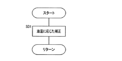
また、好適には、前記修正後エンジン回転速度算出手段は、前記自動変速機の作動油温度に基づいて前記修正後エンジン回転速度を決定するものである。このようにすれば、油温毎に異なる作動油粘度に基づく、変速時間のばらつきを抑止することができる。 Preferably, the corrected engine rotation speed calculation means determines the corrected engine rotation speed based on a hydraulic oil temperature of the automatic transmission. In this way, it is possible to suppress the variation in the shift time based on the hydraulic oil viscosity that varies depending on the oil temperature.
さらに、好適には、前記変速点リアルタイム修正手段は、予め設定された変速点修正禁止条件に該当する場合には変速点の修正を行わないものである。このようにすれば、変速点修正禁止条件に該当する場合には変速点の修正が行われることがない。 Further, it is preferable that the shift point real-time correcting means does not correct the shift point when a preset shift point correction prohibition condition is satisfied. In this way, when the shift point correction prohibition condition is satisfied, the shift point is not corrected.
以下、本発明の実施例につき、図面を参照しつつ詳細に説明する。 Hereinafter, embodiments of the present invention will be described in detail with reference to the drawings.
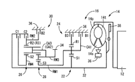
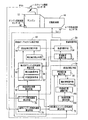
図1は、本発明の一実施例である変速制御装置が適用される車両の駆動力伝達装置10を説明する図である。この車両用動力伝達装置10は横置き型自動変速機16を有するものであって、FF(フロントエンジン・フロントドライブ)型車両に好適に採用されるものであり、走行用の駆動力源としてエンジン12を備えている。内燃機関にて構成されるエンジン12の出力は、トルクコンバータ14、自動変速機16、図示しない差動歯車装置、一対の車軸などを介して左右の駆動輪へ伝達されるようになっている。
FIG. 1 is a diagram illustrating a driving force transmission device 10 for a vehicle to which a shift control device according to an embodiment of the present invention is applied. The vehicle power transmission device 10 has a horizontal
上記トルクコンバータ14は、エンジン12のクランク軸に連結されたポンプ翼車14p、自動変速機16の入力軸32に連結されたタービン翼車14t、および一方向クラッチを介して変速機ケース36に連結された固定翼車14sを備えており、流体を介して動力伝達を行うようになっている。また、それ等のポンプ翼車14pおよびタービン翼車14tの間にはロックアップクラッチ38が設けられており、図示しない油圧制御回路の切換弁によって係合側油室および解放側油室に対する油圧供給が切り換えられることにより、係合状態、スリップ状態、或いは解放状態されるようになっており、完全係合状態とされることによってポンプ翼車14pおよびタービン翼車14tが一体回転させられるようになっている。
The
上記自動変速機16は、シングルピニオン型の第1遊星歯車装置22を主体として構成されている第1変速部24と、シングルピニオン型の第2遊星歯車装置26およびダブルピニオン型の第3遊星歯車装置28を主体として構成されている第2変速部30とを同軸線上に有し、入力軸32の回転を変速して出力歯車34から出力する。入力軸32は入力部材に相当するもので、エンジン等の走行用駆動源によって回転駆動されるトルクコンバータのタービン軸などであり、出力歯車34は出力部材に相当するものであり、カウンタ軸を介して或いは直接的に差動歯車装置と噛み合い、左右の駆動輪を回転駆動する。なお、この車両用自動変速機16は中心線に対して略対称的に構成されており、図1では中心線の下半分が省略されている。
The
上記第1変速部24を構成している第1遊星歯車装置22は、サンギヤS1、キャリアCA1、およびリングギヤR1の3つの回転要素を備えており、サンギヤS1が入力軸32に連結されて回転駆動されるとともにリングギヤR1が第3ブレーキB3を介して回転不能に変速機ケース(ハウジング)36に固定されることにより、キャリヤCA1が中間出力部材として入力軸32に対して減速回転させられて出力する。また、第2変速部30を構成している第2遊星歯車装置26および第3遊星歯車装置28は、一部が互いに連結されることによって4つの回転要素RM1〜RM4が構成されており、具体的には、第3遊星歯車装置28のサンギヤS3によって第1回転要素RM1が構成され、第2遊星歯車装置26のリングギヤR2および第3遊星歯車装置28のリングギヤR3が互いに連結されて第2回転要素RM2が構成され、第2遊星歯車装置26のキャリアCA2および第3遊星歯車装置28のキャリアCA3が互いに連結されて第3回転要素RM3が構成され、第2遊星歯車装置26のサンギヤS2によって第4回転要素RM4が構成されている。上記第2遊星歯車装置26および第3遊星歯車装置28は、キャリアCA2およびCA3が共通の部材にて構成されているとともに、リングギヤR2およびR3が共通の部材にて構成されており、且つ第2遊星歯車装置26のピニオンギヤが第3遊星歯車装置28の第2ピニオンギヤを兼ねているラビニヨ型の遊星歯車列とされている。
The first
上記第1回転要素RM1(サンギヤS3)は第1ブレーキB1によって選択的にケース36に連結されて回転停止させられ、第2回転要素RM2(リングギヤR2、R3)は第2ブレーキB2によって選択的にケース36に連結されて回転停止させられ、第4回転要素RM4(サンギヤS2)は第1クラッチC1を介して選択的に前記入力軸32に連結され、第2回転要素RM2(リングギヤR2、R3)は第2クラッチC2を介して選択的に入力軸32に連結され、第1回転要素RM1(サンギヤS3)は中間出力部材である第1遊星歯車装置22のキャリアCA1に一体的に連結され、第3回転要素RM3(キャリアCA2、CA3)は前記出力歯車34に一体的に連結されて回転を出力するようになっている。第1ブレーキB1〜第3ブレーキB3、第1クラッチC1、第2クラッチC2は、何れも油圧シリンダによって摩擦係合させられる多板式の油圧式摩擦係合装置である。
The first rotating element RM1 (sun gear S3) is selectively connected to the
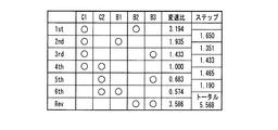
図2の作動表は、上記各変速段とクラッチC1、C2、ブレーキB1〜B3の作動状態との関係をまとめたもので、「○」は係合、「◎」はエンジンブレーキ時のみ係合を表している。各変速段の変速比は、第1遊星歯車装置22、第2遊星歯車装置26、および第3遊星歯車装置28の各ギヤ比ρ1、ρ2、ρ3によって適宜定められ、例えばρ1≒0.45、ρ2≒0.38、ρ3≒0.41とすれば、図2に示す変速比が得られ、ギヤ比ステップ(各変速段間の変速比の比)の値が略適切であるとともにトータルの変速比幅(=3.62/0.59)も6.1程度と大きく、後進変速段「Rev」の変速比も適当で、全体として適切な変速比特性が得られる。このように、本実施例の車両用自動変速機16においては、3組の遊星歯車装置22、26、28と2つのクラッチC1、C2および3つのブレーキB1〜B3を用いて前進6段の多段変速が達成されるため、3つのクラッチおよび2つのブレーキを用いる場合に比較して、クラッチが少なくなった分だけ重量やコスト、軸長が低減される。特に、第2変速部30を構成しているシングルピニオン型の第2遊星歯車装置26およびダブルピニオン型の第3遊星歯車装置28はラビニヨ型の遊星歯車列とされているため、部品点数や軸長が一層低減される。
The operation table of FIG. 2 summarizes the relationship between the above-mentioned shift speeds and the operation states of the clutches C1, C2 and the brakes B1 to B3, where “◯” indicates engagement and “◎” indicates engagement only during engine braking. Represents. The gear ratio of each gear stage is appropriately determined by the gear ratios ρ1, ρ2, and ρ3 of the first
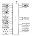
図3は、上記自動変速機16の変速を制御するための自動変速制御装置として機能する電子制御装置40の入出力を示す図である。図3において、イグニションスイッチからのスイッチオン信号、エンジン回転センサからのエンジン回転速度NEを示す信号、エンジン水温センサからのエンジン水温Twを示す信号、エンジン吸気温度センサからのエンジン吸気温度Taを示す信号、スロットル開度センサからのスロットル開度θthを示す信号、アクセル開度センサからのアクセル開度θaccを示す信号、ブレーキスイッチからのブレーキ操作を示す信号、車速センサからの車速Vを示す信号、シフトレバー位置センサからのシフトレバーの前後位置を示す信号、シフトレバー位置センサからのシフトレバーの左右位置を示す信号、タービン回転センサからのタービン翼車14tの回転速度Ntを示す信号、自動変速機16の出力歯車(出力軸)の回転速度Noutを示す信号、自動変速機16の油温Toilを示す信号、変速パターン切換スイッチの操作位置を示す信号、ABS用電子制御装置からの信号、VSC/TRCの用電子制御装置からの信号、A/C用電子制御装置からの信号などが電子制御装置40に入力される。
FIG. 3 is a diagram showing the input / output of the
上記電子制御装置40は、たとえばCPU、ROM、RAM、インターフェースなどを含む所謂マイクロコンピュータであって、予めROMに記憶されたプログラムに従って入力信号を処理し、スタータへの駆動信号、燃料噴射弁への燃料噴射信号、自動変速機16の変速制御用オンオフ弁のソレノイドへの信号、自動変速機16の油圧制御用リニヤソレノイド弁のソレノイドへの信号、シフトポジション表示器への表示信号、ABS用電子制御装置への信号、VSC/TRC用電子制御装置への信号、A/C用電子制御装置への信号などをそれぞれ出力する。
The
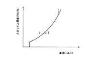
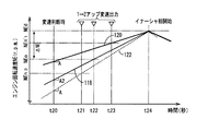
上記電子制御装置40は、たとえば、たとえば図4に一部を示す予め記憶された変速線図から実際の車速Vとアクセル開度θaccまたはスロットル開度θthとに基づいて変速判断し、判断された変速を実行させるための変速制御用オンオフ弁を駆動するための変速出力を行う。たとえば図4の1→2変速線の最大アクセル開度θaccmax側は、平坦値走行においてアクセル開度θaccまたはスロットル開度θthが100%またはその付近である全開スロットル時のアップ変速である全開アップ変速に際しては、車両の最大駆動力(出力)が得られるように設定されている。また、電子制御装置40は、たとえば登坂路走行、降坂走行、牽引走行などの走行抵抗が大きく変化した走行状態における全開アップ変速に際しても、車両の最大駆動力(出力)を得るため、エンジン回転速度NEが予め設定されたレッドゾーン域またはその上に設定された燃料遮断域内に入らない範囲で高い回転速度となるように、最適な時期に変速出力を行うか、或いは予め設定された変速線(変速パターン)を変更し、以後の全開アップ変速において最適な時期に変速出力が行われるようする。すなわち、実行された変速の結果に基づいて、最適な変速出力の時期を学習制御する。
The
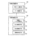
図5は、上記電子制御装置40の制御機能の要部を説明する機能ブロック線図である。図5において、電子制御装置40は、その機能面から、変速制御手段50、変速点リアルタイム修正手段60のほか、変速点補正手段70などに分けられる。変速制御手段50は、変速線図を予め記憶する変速線図記憶手段52と、その変速線図記憶手段52に記憶された変速線図から車両走行状態たとえば実際の車速Vとアクセル開度θaccまたはスロットル開度θthとに基づいて変速判断する変速判断手段54とを備え、その判断された変速を実行させるための変速制御用オンオフ弁を駆動するための変速出力を行う。また、前記変速線図記憶手段52は、後述する変速点補正手段70の出力に応じ、予め記憶する変速線図を適宜補正し得るものであり、前記変速判断手段54は、後述する変速点修正実行手段94により修正された変速点を考慮した変速出力を行い得るものである。
FIG. 5 is a functional block diagram illustrating the main part of the control function of the
変速点補正手段70は、基準エンジン回転加速度算出手段74、エンジン回転加速度算出手段76、推定最大エンジン回転速度算出手段72、加速度変動検出手段102、学習補正値調整手段100、補正値制限手段82、学習補正値算出手段80などを備え、これらの手段により、実際の走行における変速により学習を行い、その結果に応じて前記変速線図記憶手段52に記憶された変速線図を補正する。すなわち、学習制御手段70は、パワーオン走行時でのアップ変速出力後のエンジン回転速度の最大値を、車両の加速度に影響しない基準走行状態における値に置換した推定最大エンジン回転速度を推定し、該推定最大エンジン回転速度と前記目標最大エンジン回転速度との偏差に基づいて前記学習補正値を算出する。
The shift
基準エンジン回転加速度算出手段74は、予め実験的に求められ且つ記憶された関係から、車両の走行状態たとえば車速V、スロットル開度θth、自動変速機16の入力トルクTinの少なくとも1つに基づいて、基準走行状態におけるアップ変速判断時点のエンジン回転加速度である、基準エンジン回転加速度A2(rad/sec2 )の値が算出される。ここで、基準エンジン回転加速度とは、車両の加速度に影響を及ぼさない基準走行状態、たとえば、所定重量の運転手のみが乗車した状態などの予め定められた車両の基準人数乗車状態であって0%の勾配の路面を車両が走行している状態におけるエンジン12の回転加速度であって、本実施例においては、上記アップ変速判断時点の走行状態から算出される基準走行状態におけるエンジン回転加速度A2である。
The reference engine rotational acceleration calculation means 74 is based on at least one of the vehicle running state, for example, the vehicle speed V, the throttle opening θth, and the input torque Tin of the
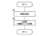
エンジン回転加速度算出手段76は、アップ変速判断時点における、エンジン12の回転加速度A(rad/sec2 )を算出する。本実施例においては、エンジン回転加速度Aの値はエンジン12に設けられたエンジン回転速度センサ46によって検出されたエンジン回転速度NEの微小単位時間あたりの変化量dNE/dtを逐次算出することによって得られる。なお、通常、エンジン回転速度NEは変動(ノイズ)が大きいので、この際、図示しない平滑化フィルタなどにより、その移動平均などのフィルタ処理がされた後のエンジン回転速度NEが用いられる。
The engine rotational acceleration calculating means 76 calculates the rotational acceleration A (rad / sec 2 ) of the
推定最大エンジン回転速度算出手段72は、前記基準エンジン回転加速度算出手段74によって算出された基準エンジン回転加速度A2における推定最大エンジン回転速度NEcを算出する。具体的には、推定最大エンジン回転速度算出手段72は、前記基準エンジン回転加速度算出手段74によって算出された基準エンジン回転加速度A2および、前記エンジン回転加速度算出手段76によって算出されたアップ変速出力時点のエンジン回転加速度A、エンジン回転速度センサ46により検出されたアップ変速出力時点におけるエンジン12の回転速度NE1、および前記アップ変速実行中のイナーシャ相開始時点におけるエンジン12の回転速度NE2から、次の式(1)により求められる。
NEc=NE1+(NE2−NE1)×A2/A ・・・(1)
The estimated maximum engine rotation speed calculation means 72 calculates the estimated maximum engine rotation speed NEc at the reference engine rotation acceleration A2 calculated by the reference engine rotation acceleration calculation means 74. Specifically, the estimated maximum engine rotation speed calculation means 72 includes the reference engine rotation acceleration A2 calculated by the reference engine rotation acceleration calculation means 74 and the upshift output time point calculated by the engine rotation acceleration calculation means 76. From the engine rotational acceleration A , the rotational speed NE1 of the
NEc = NE1 + (NE2-NE1) × A2 / A (1)
補正値制限手段82は、後述する学習補正値算出手段80の実行中に適宜実行されるものであって、学習補正値算出手段80において用いられる1回あたりの変速点学習値ΔG、および/または、学習後の全体学習量G(N)の値が、予め定められた範囲を超えていないかが判定され、前記範囲を超えている場合には、それらの値を前記範囲を満たすような制限を加える。例えば、前記ΔGについて考えると、後述する学習補正値算出手段80において算出される1回あたりの変速点学習値ΔGは、算出された後、実際の学習に用いられる前に本補正値制限手段82に渡される。そして、ΔGが、予め定められた2つの定数ΔGmin、ΔGmaxによって、ΔGmin≦ΔG≦ΔGmaxのように定められた前記範囲を超えているか否かを判定し、ΔGが前記範囲の上限ΔGmaxを上回っている場合にはΔG=ΔGmaxとし、ΔGが前記範囲の下限ΔGminを下回っている場合にはΔG=ΔGminとする、いわゆるガード処理を行う。一方、ΔGが前記範囲を満たす場合には、特別な処理を行わない。以上の処理が行われたΔGが学習補正値算出手段80に戻され、実際の学習が行われることとなる。また、学習後の全体学習量G(N)の場合は、後述する学習補正値算出手段80によって算出された全体学習量G(N)算出された後、変速点の補正に用いられる前に本補正値制限手段82に渡される。そして、G(N)が、予め定められた2つの定数Gmin、Gmaxによって、Gmin≦G(N)≦Gmaxのように定められた前記範囲を超えているか否かを判定し、G(N)が前記範囲の上限Gmaxを上回っている場合にはG(N)=Gmaxとし、G(N)が前記範囲の下限Gminを下回っている場合にはG(N)=Gminとする、ガード処理を行う。一方、G(N)が前記範囲を満たす場合には、特別な処理を行わない。以上の処理が行われたG(N)が学習値補正手段80に戻され、その後変速点の補正が行われる。
The correction
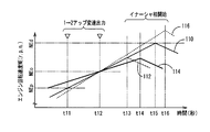
学習補正値算出手段80は、1回の変速が行われる毎に、前記推定最大エンジン回転速度算出手段72により算出された推定最大エンジン回転速度NEcと、目標最大エンジン回転速度NEdとの偏差ΔNE1を算出し、その偏差ΔNE1の大きさに応じた学習を行い、前記変速線図記憶手段52に記憶された変速点を補正する。ここで、目標最大エンジン回転速度NEdは、変速に伴うイナーシャ相の開始時点前後において、エンジン12の回転速度がその値を超えることがなく、かつできる限りその値に近づくように、予め設定された回転速度であり、たとえば、エンジン12の耐久性が損なわれないように設定されている燃料遮断回転速度NEfcutよりも低い側、好適にはそれよりも低く設定されているエンジン12のレッドゾーンの下限値NEredよりも所定値だけ低い側においてそれに近い値となるように設定されている。
The learning correction value calculating means 80 obtains a deviation ΔNE1 between the estimated maximum engine speed NEc calculated by the estimated maximum engine speed calculating means 72 and the target maximum engine speed NEd every time one shift is performed. The shift point stored in the shift diagram storage means 52 is corrected by calculating and learning according to the magnitude of the deviation ΔNE1. Here, the target maximum engine rotational speed NEd is set in advance so that the rotational speed of the
具体的にはまず、前記算出された偏差ΔNE1に基づき、1回あたりの変速点学習値ΔG(=K×ΔNE1、但しKは学習の重みを決定する学習補正係数(「学習ゲイン」ともいう。)であって、予め与えられる。)を決定する。そして、このようにして算出され、必要に応じて前記補正値制限手段82によってガード処理のされたΔGを前回の変速時までの全体学習量G(N−1)に加える事により、今回の変速における学習を加えた全体学習量G(N)(=G(N−1)+ΔG)とする。そして、算出された全体学習量G(N)に対し、必要に応じて前記補正値制限手段82によってガード処理がされる。 Specifically, first, based on the calculated deviation ΔNE1, one shift point learning value ΔG (= K × ΔNE1, where K is also referred to as a learning correction coefficient (“learning gain”) that determines a learning weight. ) And given in advance). The current shift is calculated by adding ΔG calculated in this way and guarded by the correction value limiting means 82 as necessary to the total learning amount G (N−1) up to the previous shift. The total learning amount G (N) (= G (N−1) + ΔG) obtained by adding learning in FIG. Then, a guard process is performed on the calculated total learning amount G (N) by the correction value limiting means 82 as necessary.
また、学習補正値算出手段80は、算出され、必要に応じて前記補正値制限手段82によってガード処理がされた全体学習量G(N)に基づいて、変速線図記憶手段52に記憶された変速線図の補正を行う。すなわち、前記学習された全体学習量G(N)により、たとえば図4の変速線を実線から破線へ修正してアップ変速点たとえば1→2アップ変速点を学習によって補正し、これにより判断される全開アップ変速において登坂路走行、降坂走行、牽引走行などの走行抵抗が大きく変化した走行状態に拘わらず最大出力が得られるようにする。 The learning correction value calculation means 80 is stored in the shift diagram storage means 52 based on the total learning amount G (N) calculated and guarded by the correction value restriction means 82 as necessary. The shift map is corrected. That is, based on the learned total learning amount G (N), for example, the shift line in FIG. In the fully open upshift, the maximum output is obtained regardless of the traveling state in which the traveling resistance such as the uphill traveling, the downhill traveling, and the towing traveling is greatly changed.
このとき、変速点の補正は、前記推定最大エンジン回転速度NEcと前記目標最大エンジン回転速度NEdとの偏差ΔNE1が大きくなるほど、高車速側へ大きくずれるようにされる。すなわち、図4における補正は、ΔNE1が負の値となった場合であって、元の変速点から低車速側へ補正された場合を示している。また、学習に際し、学習補正値算出手段80に与えられるのはΔNE1、すなわちエンジン回転速度の偏差である一方、学習補正値算出手段80が実際に学習を行う値である1回あたりの学習量ΔG、および学習補正値算出手段80によって算出され、変速点の補正に用いられる値である全体学習量G(N)は図4に示されるように車速であるから、これらの次元は異なるものであるが、前記学習補正係数Kによって学習の重みの決定がされるのと同時に、あるいは特に示されない一般的な方法によって別途、変換されればよい。 At this time, the shift point is corrected so as to be shifted to the higher vehicle speed side as the deviation ΔNE1 between the estimated maximum engine speed NEc and the target maximum engine speed NEd increases. That is, the correction in FIG. 4 shows a case where ΔNE1 becomes a negative value and is corrected from the original shift point to the low vehicle speed side. In learning, ΔNE1 that is given to the learning correction value calculation means 80, that is, a deviation of the engine rotation speed, while the learning correction value calculation means 80 actually learns a learning amount ΔG per time. , And learning correction value calculation means 80, and the total learning amount G (N), which is a value used to correct the shift point, is the vehicle speed as shown in FIG. 4, so these dimensions are different. However, at the same time as the learning weight is determined by the learning correction coefficient K, it may be converted separately by a general method not specifically shown.
加速度変動検出手段102は、車両の加速度a(m/sec2 )に変動が生じた場合にこれを検出する。また、学習補正値調整手段100は、前記加速度変動検出手段102において車両加速度aの変動が検出された場合において、学習補正値算出手段80に対し学習補正値算出手段80が算出する全体学習量G(N)の値が検出した車両加速度aの変動da/dtの大きさに応じて調整されるようにする。例えば前記車両加速度aの変動da/dtの値が大きくなるほど、前記学習補正係数Kや、前記ガード処理の際に用いられるガード値ΔGmax、ΔGminの大きさを小さくすることによって、前記車両加速度aの変動da/dtが大きい場合の学習結果の全体の学習結果に与える影響を小さくするとともに、かかる車両加速度aの変動da/dtが大きい場合であっても学習を中断することがない。なお、これらの詳細な作動については後述する。
The acceleration fluctuation detecting means 102 detects when a fluctuation occurs in the vehicle acceleration a (m / sec 2 ). Further, the learning correction
変速点リアルタイム修正手段60は、前記基準エンジン回転加速度算出手段74、前記エンジン回転加速度算出手段76、加速度補正係数算出手段90、修正後エンジン回転速度算出手段92、修正値制限手段96、変速点修正実行手段94、修正実行禁止手段98等を備え、これらの手段により、変速点補正手段70により補正された変速点を、車両の加速度のばらつきに応じてリアルタイムで修正する。すなわち、変速点リアルタイム修正手段60は、パワーオン走行時でのアップ変速判断時点の実際のエンジン回転加速度と、その実際のエンジン回転加速度の値を車両の加速度に影響しない基準走行状態における値に置換した基準エンジン回転加速度との比の値と、前記目標エンジン回転速度とに基づいて前記変更された変速点をリアルタイムで修正する。なお、本実施例においてはエンジン回転加速度関連値としてはエンジン回転加速度が用いられる。
The shift point real-
加速度補正係数算出手段90においては、前記エンジン回転加速度算出手段76において算出されたエンジン回転加速度Aの値と、前記基準エンジン回転加速度算出手段74によって算出された前記基準エンジン回転加速度A2の値の比である加速度補正係数γが算出される。 In the acceleration correction coefficient calculating means 90, the ratio between the value of the engine rotational acceleration A calculated by the engine rotational acceleration calculating means 76 and the value of the reference engine rotational acceleration A2 calculated by the reference engine rotational acceleration calculating means 74. An acceleration correction coefficient γ is calculated.
修正後エンジン回転速度算出手段92は、前記加速度補正係数算出手段90において算出された加速度補正係数γ及び、目標最大エンジン回転速度NEdと、前記変速点補正手段70において算出された補正後の変速点におけるエンジン回転速度である補正後エンジン回転速度NEoとの偏差ΔNE2(=NEd−NEo)に基づいて、予め記憶された関係式を用いて、修正後の変速点におけるエンジン回転速度である修正後エンジン回転速度NEnを算出する。ここで、目標最大エンジン回転速度NEdは、変速に伴うイナーシャ相の開始時点前後において、エンジン12の回転速度がその値を超えることがなく、かつできる限りその値に近づくように、予め設定された回転速度であり、たとえば、エンジン12の耐久性が損なわれないように設定されている燃料遮断回転速度NEfcutよりも低い側、好適にはそれよりも低く設定されているエンジン12のレッドゾーンの下限値NEredよりも所定値だけ低い側においてそれに近い値となるように設定されている。
The corrected engine rotation speed calculation means 92 includes the acceleration correction coefficient γ calculated by the acceleration correction coefficient calculation means 90, the target maximum engine rotation speed NEd, and the corrected shift point calculated by the shift point correction means 70. Based on the deviation ΔNE2 (= NEd−NEo) from the corrected engine rotation speed NEo, which is the engine rotation speed at, the corrected engine, which is the engine rotation speed at the corrected shift point, using a relational expression stored in advance. The rotational speed NEn is calculated. Here, the target maximum engine rotational speed NEd is set in advance so that the rotational speed of the
ここで、前記修正後エンジン回転速度算出手段92に予め記憶された関係式とは、例えば、前記加速度補正係数γに、前記目標最大エンジン回転速度NEdと、前記補正後エンジン回転速度NEoに基づいて補正された変速点におけるエンジン回転速度NEoとの偏差ΔNE2を乗算し、該乗算の積を、前記目標最大エンジン回転速度NEdから減算するもの、すなわち、次式(2)
NEn=NEd−(NEd−NEo)×A/A2 ・・・(2)
である。
Here, the relational expression stored in advance in the corrected engine rotational speed calculation means 92 is, for example, based on the acceleration correction coefficient γ, the target maximum engine rotational speed NEd, and the corrected engine rotational speed NEo. Multiplying the deviation ΔNE2 from the engine speed NEo at the corrected shift point and subtracting the product of the multiplication from the target maximum engine speed NEd, that is, the following equation ( 2 )
NEn = NEd− (NEd−NEo) × A / A2 ( 2 )
It is.
修正値制限手段96は、修正後エンジン回転速度算出手段92の実行に合わせて実行されるものであって、修正後エンジン回転速度算出手段92によって算出された修正後エンジン回転速度NEnの値が、予め定められた範囲を超えていないかが判定され、前記範囲を超えている場合には、それらの値が前記範囲を満たすような制限を加える。具体的には例えば、修正後エンジン回転速度算出手段92が修正後エンジン回転速度NEnの値を算出すると、そのNEnの値が修正値制限手段96に渡される。そして、修正値制限手段96は、前記NEnの値について、予め定められた2つの定数NEnmin、およびNEnmaxによってNEnmin≦NEn≦NEnmaxのように定められた前記範囲を超えているか否かを判定し、前記NEnが前記範囲の上限NEnmaxを上回っている場合には前記修正後エンジン回転速度NEnの値を新たに前記範囲の上限NEmaxとし(NEn=NEnmax)、前記NEnが前記範囲の下限NEnminを下回っている場合には前記修正後エンジン回転速度NEnの値を新たに前記範囲の下限NEminとする(NEn=NEnmin)、いわゆるガード処理を行う。一方、NEnが前記範囲を満たす場合には、特別な処理を行わない。以上の処理が行われたNEnが、以降、修正後エンジン回転速度NEnとして用いられる。
The corrected
AT油温反映手段97は、修正後エンジン回転速度算出手段92の実行に合わせて実行されるものであって、修正後エンジン回転速度算出手段92によって算出された修正後エンジン回転速度NEnの値に対し、前記変速判断時点における自動変速機16の作動油の温度Toilによって変化する作動油の粘度等の影響を反映させる。具体的には、修正後エンジン回転速度NEnの値に、自動変速機16の作動油の温度Toil毎に予め定められた係数μを乗ずる。そして、この結果得られた数値NEn’(=NEn×μ)を、新たな修正後エンジン回転速度とする。尚、前記予め定められた係数μとは、例えば、自動変速機16の変速出力時からイナーシャ相開始時までに要する時間とその際の自動変速機16の作動油の油温Toilとの関係から実験的に得られた値である。
The AT oil temperature reflecting means 97 is executed in accordance with the execution of the corrected engine rotational speed calculating means 92, and is set to the value of the corrected engine rotational speed NEn calculated by the corrected engine rotational speed calculating means 92. On the other hand, the influence of the viscosity etc. of the hydraulic fluid which changes with the hydraulic oil temperature Toil of the
変速点修正実行手段94は、修正後エンジン回転速度算出手段92によって算出された修正後エンジン回転速度NEn’の値において変速出力が実行されるよう、前記変速判断手段54に変速点を修正させる。すなわち、エンジンの回転速度が修正後エンジン回転速度NEn’に達した時点において変速出力がなされるようにされる。 The shift point correction execution means 94 causes the shift determination means 54 to correct the shift point so that the shift output is executed at the value of the corrected engine rotation speed NEn ′ calculated by the corrected engine rotation speed calculation means 92. That is, a shift output is made when the engine speed reaches the corrected engine speed NEn '.
修正実行禁止手段98は、予め設定された変速点修正禁止条件に該当する場合には、前記変速点修正実行手段94による変速点の修正を禁止する。ここで、前記変速点修正禁止条件とは、例えば、アップ変速判断時が直前に行われたダウン変速から予め定められた一定期間tdが経過していないことや、例えば自動変速機16の出力軸回転数Noutの微小単位時間あたりの変動量dNout/dtが予め定められた値よりも大きいことにより車両が悪路を走行していると判定されること、などの条件のいずれかあるいは複数によって構成される。これは、例えば、変速点の修正に係るアップ変速が、エンジン回転数の変化が大きいダウン変速の直後に行われる場合であることがこれに該当する。すなわち、キックダウンのようなアクセル全開によるダウン変速が行われた場合、エンジン回転速度の変化が大きいため、それに続いて行われるアップ変速において変速点の修正を行おうとすると、変速点を低車速(低エンジン回転速度)側に大幅に修正してしまい、その結果、アップ変速がダウンシフトの直後に行われ、いわゆるビジーシフトが生ずるといった、意図しない誤反映となるためである。このように、変速点修正禁止条件に該当する場合には、修正実行禁止手段98は、前記変速点修正実行手段94が変速点を修正するのを禁止する。
The correction
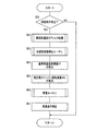
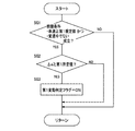
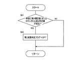
図6乃至図9及び図11乃至図20は、前記電子制御装置40の制御作動の要部すなわち変速点の修正制御作動の一例を説明するフローチャートである。図6において、ステップ(以下「ステップ」を省略する。)SA1では、本制御の実行の前提となる前提条件が成立したか否かが判断される。この実行条件とは、例えば、スロットル開度θthが所定値(たとえば100%またはその近傍の値)以上であることや、自動変速機16の作動油の油温Toilが所定値以上であること、トーイングモード等の所定の走行モードが適用されていること、などの条件のいずれかあるいは複数によって構成される。そして、SA1の判断が肯定された場合、すなわち、前記実行条件が満たされる場合には、続くSA2が実行され、また、SA1の判断が否定された場合には、本制御は実行されることがなく、本フローチャートは終了させられる。
FIGS. 6 to 9 and FIGS. 11 to 20 are flowcharts for explaining an example of the control operation of the
修正実行禁止手段98に対応するSA2においては、本制御による変速点の修正を禁止する変速点修正禁止条件に該当しないか否かが判断される。この変速点修正禁止条件は、例えば、ダウンシフト後、予め定められた一定期間tdが経過していないことや、例えば自動変速機16の出力軸回転数Noutの微小単位時間あたりの変動量dNout/dtが予め定められた値よりも大きいことにより車両が悪路を走行していると判定されること、などの条件のいずれかあるいは複数によって構成される。そして、SA2の判断が肯定された場合、すなわち、前記変速点修正禁止条件に該当しない場合には、続くSA3以降の本発明の変速点の修正制御が実行される一方、SA2の判断が否定された場合には、本制御は実行されることがなく、本フローチャートは終了させられる。
In SA2 corresponding to the correction execution prohibition means 98, it is determined whether or not the shift point correction prohibition condition for prohibiting the correction of the shift point by this control is not satisfied. This shift point correction prohibition condition is, for example, that a predetermined period td has not elapsed after downshifting, or, for example, the fluctuation amount dNout / min of the output shaft rotation speed Nout of the
エンジン回転加速度算出手段76および基準エンジン回転加速度算出手段74に対応するSA3においては、エンジン回転加速度Aおよび、基準エンジン回転加速度A2が算出される。すなわち、SA3では、まず、アップ変速判断時点においてエンジン回転速度センサ46により測定されるエンジン回転速度NEの微小単位時間あたりの変化量dNE/dtとしてエンジン回転加速度Aが算出され、また、アップ変速判断時点における車両の走行状態、たとえば車速V、スロットル開度θth、自動変速機16の入力トルクTinの少なくとも1つに基づいて、予め実験的に求められ、かつ記憶された関係から、基準エンジン回転加速度A2が算出される。
In SA3 corresponding to the engine rotation acceleration calculation means 76 and the reference engine rotation acceleration calculation means 74, the engine rotation acceleration A and the reference engine rotation acceleration A2 are calculated. That is, in SA3, first, the engine rotational acceleration A is calculated as the amount of change dNE / dt per minute unit time of the engine rotational speed NE measured by the engine rotational speed sensor 46 at the time of upshift determination. Based on at least one of the running state of the vehicle at the time, for example, the vehicle speed V, the throttle opening θth, and the input torque Tin of the
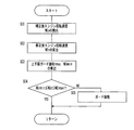
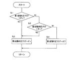
加速度補正係数算出手段90に対応するSA4においては、図7に示す加速度補正係数算出ルーチンが実行され、加速度補正係数γが算出される。図7に示す加速度補正係数算出ルーチンは、まずSB1において、その実行の前提条件を満たすかが判断される。この前提条件とは、たとえば、図示しない加速度補正選択スイッチが運転者により操作され、オンとされていること等である。そして、本判断が肯定された場合はSB3以降が実行され、一方否定された場合はSB2が実行される。 In SA4 corresponding to the acceleration correction coefficient calculation means 90, the acceleration correction coefficient calculation routine shown in FIG. 7 is executed to calculate the acceleration correction coefficient γ. In the acceleration correction coefficient calculation routine shown in FIG. 7, it is first determined in SB1 whether the preconditions for execution thereof are satisfied. The precondition is, for example, that an acceleration correction selection switch (not shown) is operated by a driver and turned on. If this determination is affirmed, SB3 and subsequent steps are executed, while if negative, SB2 is executed.
SB2においては、加速度補正が行われないようにすべく、加速度補正係数γの値がγ=1とされる。すなわち、γ=1とすると、本ルーチンの終了後図6に戻ってSA4以降が実行されるものの、変速点の修正は行われない結果となる。一方、SB3においては、先に実行されたSA3において算出されたアップ変速判断時のエンジン回転加速度Aおよび基準エンジン回転加速度A2の値から、加速度補正係数γが、γ=A/A2のように算出される。また、SB3に続いて実行されるSB4においては、SB3において算出された加速度補正係数γが、予め設定された範囲γmin≦γ≦γmaxを満たすか否かが判断される。そして、当該判断が否定された場合、すなわちγが前記範囲を満たさない場合には、SB5が実行され、γが前記範囲の上限γmaxを上回る場合にはγの値が新たにγmaxとされ、一方、γが前記範囲の下限γminを下回る場合には、γの値が新たにγminとされることとなる。一方、SB4の判断が肯定された場合にはSB3において算出された加速度補正係数γがそのまま用いられる。以上のようにして、加速度補正係数γが算出されると、本ルーチンは終了する。 In SB2, the value of the acceleration correction coefficient γ is set to γ = 1 so that the acceleration correction is not performed. That is, if γ = 1, the routine returns to FIG. 6 after the end of this routine, and after SA4 is executed, the shift point is not corrected. On the other hand, in SB3, the acceleration correction coefficient γ is calculated as γ = A / A2 from the values of the engine rotation acceleration A and the reference engine rotation acceleration A2 at the time of the upshift determination calculated in SA3 executed earlier. Is done. Further, in SB4 executed subsequent to SB3, it is determined whether or not the acceleration correction coefficient γ calculated in SB3 satisfies a preset range γmin ≦ γ ≦ γmax. When the determination is negative, that is, when γ does not satisfy the range, SB5 is executed, and when γ exceeds the upper limit γmax of the range, the value of γ is newly set as γmax, , Γ falls below the lower limit γmin of the range, the value of γ is newly set to γmin. On the other hand, when the determination at SB4 is affirmed, the acceleration correction coefficient γ calculated at SB3 is used as it is. When the acceleration correction coefficient γ is calculated as described above, this routine ends.
図6に戻って、修正後エンジン回転速度算出手段92および修正値制限手段96に対応するSA5においては、図8に示す修正後エンジン回転速度算出ルーチンが実行される。図8の修正後エンジン回転速度算出ルーチンは、まず、SC1において、前記変速点補正手段70において算出された学習後の変速点におけるエンジン回転速度NEoが読み出される。ここで、学習後の変速点とは、変速点補正手段70によって学習された、自動変速機16のばらつきに応じた学習補正後の変速点であり、その値は、例えば、変速点補正手段70によって変更され変速線図記憶手段52に記憶された変速線図から読み出されることができる。
Returning to FIG. 6, in SA5 corresponding to the corrected engine rotation speed calculation means 92 and the correction value restriction means 96, the corrected engine rotation speed calculation routine shown in FIG. 8 is executed. In the modified engine rotation speed calculation routine of FIG. 8, first, in SC1, the engine rotation speed NEo at the learned shift point calculated by the shift point correction means 70 is read. Here, the shift point after learning is the shift point after learning correction according to the variation of the
続くSC2においては、SA4において算出された加速度補正係数γ、SC1において読み出されたNEo、および、予め設定された目標最大エンジン回転速度NEdと、予め記憶された関係式、例えば前記式(2)とから、修正後エンジン回転速度NEnが算出される。 In the subsequent SC2, the acceleration correction coefficient γ calculated in SA4, the NEo read in SC1, and the preset target maximum engine speed NEd, and a previously stored relational expression, for example, the expression ( 2 ) above. From the above, the corrected engine speed NEn is calculated.
続くSC3〜SC5は修正値制限手段96に対応するものである。まず、SC3においては、修正値が満たすべき範囲を設定する上限値NEnmaxおよび下限値NEnminが設定される。たとえば、上限値NEnmaxは、事前に設定された所定値α1と、SC1において読み出された、前記変速点補正手段70において算出された学習後の変速点におけるエンジン回転速度NEoとの和(NEo+α1)と、目標最大エンジン回転速度NEdのうちいずれか小さい値(min(NEo+α1,NEd))が用いられ、下限値NEnminは、前記変速点補正手段70において算出された学習後の変速点におけるエンジン回転速度NEoから、事前に設定された所定値α2を減じた値が用いられ得る。
Subsequent SC3 to SC5 correspond to the correction
SC4においては、SC2において算出された修正後エンジン回転速度NEnの値が、SC3において設定されたNEnmaxおよびNEnminによって構成される範囲、すなわち、NEnmin≦NEn≦NEnmaxを満たすか否かが判断される。そして、本判断が否定される場合にはSC5が実行され、一方本判断が肯定される場合には、SC2において算出されたNEnがそのまま修正後エンジン回転速度として用いられる。 In SC4, it is determined whether or not the value of the corrected engine speed NEn calculated in SC2 satisfies the range constituted by NEnmax and NEmin set in SC3, that is, NEmin ≦ NEn ≦ NEnmax. If this determination is negative, SC5 is executed. On the other hand, if this determination is affirmative, NEn calculated in SC2 is used as it is as the corrected engine speed.
SC5においては、SC2において算出された修正後エンジン回転速度NEnの値が、SC3において設定されたNEnmaxを上回っている場合には、NEnの値が新たにNEnmaxとされ(NEn=NEnmax)、一方、NEnの値がNEnminを下回っている場合には、NEnの値が新たにNEnminとされる(NEn=NEnmin)、いわゆるガード処理が行われる。以上により、NEnの値が定められると、本ルーチンは終了する。 In SC5, when the value of the corrected engine speed NEn calculated in SC2 exceeds the Nenmax set in SC3, the value of NEn is newly set to NEnmax (NEn = NEnmax), When the value of NEn is lower than NEnmin, a so-called guard process is performed in which the value of NEn is newly set to NEnmin (NEn = NEnmin). As described above, when the value of NEn is determined, this routine ends.
図6に戻って、AT油温反映手段97に対応するSA6においては、図9に示す自動変速機作動油温反映ルーチンが実行される。図9の自動変速機作動油温反映ルーチンにおいては、SD1において、SA5で算出された修正後エンジン回転速度NEnの値が、アップ変速判断時の自動変速機16の作動油の油温Toilの値に応じて補正される。この補正により、油温反映後の修正後エンジン回転速度NEn’は、例えば、予め実験的に求められ、記憶された自動変速機16の作動油温Toilと補正係数μの関係を用い、SA5で算出された修正後エンジン回転速度NEnの値に前記補正係数μを乗ずることによって、すなわち、NEn’=NEn×μ のように算出される。
Returning to FIG. 6, in SA6 corresponding to the AT oil temperature reflecting means 97, the automatic transmission operating oil temperature reflecting routine shown in FIG. 9 is executed. In the automatic transmission hydraulic oil temperature reflection routine of FIG. 9, in SD1, the value of the corrected engine rotational speed NEn calculated in SA5 is the value of the hydraulic oil temperature Toil of the
図6に戻って、変速点修正実行手段94に相当するSA7においては、アクセル開度が全開若しくは略全開であって、エンジン12の回転速度が、SA6において算出された自動変速機16の作動油の油温Toilが反映された修正後エンジン回転速度NEn’となった時点において変速判断手段54による変速出力が実行されるように、変速点の修正がされる。尚、変速点はたとえば、図4に示すような、車速V(km/h)とアクセル開度θacc(%)を軸とする平面で定義される座標上に示されるものであるから、修正後エンジン回転速度NEn’(rpm)は、ギヤ比等を考慮して適宜その単位が換算され、例えば、図4における破線で表されるように、変速線上にエンジン回転数の修正が反映されることとなる。
Returning to FIG. 6, in SA7 corresponding to the shift point correction execution means 94, the accelerator opening is fully open or substantially fully open, and the rotational speed of the
図10は、前記学習補正値調整手段100および加速度変動検出手段102の詳細な制御機能の要部を説明する機能ブロック線図である。図10に示すように、学習補正値調整手段100は、学習ゲイン調整手段140、ガード値調整手段142などからなる。また、加速度変動検出手段102は、加速度フィルタ処理手段144、第1変動検出手段146、第2変動検出手段148、変動検出判定手段150などからなる。
FIG. 10 is a functional block diagram for explaining a main part of detailed control functions of the learning correction value adjusting means 100 and the acceleration
学習ゲイン調整手段140は、前記加速度変動検出手段102が車両加速度aの変動を検出した場合において、学習補正値算出手段80において用いられる学習ゲインKの値をエンジン回転加速度の変動を検出しない場合に比べて小さい値K’とする。ここで、K’は例えばK’=K×αのように定義され、αは低減の度合いを決定する係数であり、例えば0.5のように予め定義される。 The learning gain adjusting means 140 is the case where the value of the learning gain K used in the learning correction value calculating means 80 is not detected as a fluctuation in engine rotational acceleration when the acceleration fluctuation detecting means 102 detects a fluctuation in the vehicle acceleration a. A smaller value K ′ is set. Here, K ′ is defined as K ′ = K × α, for example, and α is a coefficient that determines the degree of reduction, and is defined in advance as 0.5, for example.
ガード値調整手段142は、前記加速度変動検出手段102が車両加速度aの変動を検出した場合において、補正値制限手段82によって1回あたりの変速点学習値ΔGをガード処理する際に用いられる範囲の上限と下限を決定する値であるガード値ΔGmaxおよびΔGminの値を、車両加速度aの変動を検出しない場合に比べて小さい値ΔGmax’およびΔGmin’とする。ここで、ΔGmax’=ΔGmax×β1、ΔGmin’=ΔGmin×β2であって、β1およびβ2は低減の度合いを決定する係数であり、例えばβ1=β2=0.5のように予め定義される。
The guard value adjusting means 142 is a range used when the shift value learning value ΔG per time is guard-processed by the correction
加速度フィルタ処理手段144は、車両加速度aの値に対しフィルタ処理を実行し、フィルタ処理後の車両加速度asを得る。具体的には前記フィルタ処理は、例えば高速フーリエ変換(FFT)などであり、車両が振動する特定の周波数が予測されるなどにより限定される場合には、前記特定の周波数を除去することにより処理後の車両加速度asを用いることで車両加速度aの変動を低減することができる。なお、前記車両が振動する特定の周波数が予測できる場合とは、例えば車両が波状路を走行する場合に例えば10Hz等の共振振動が発生することが予測できる場合等である。 The acceleration filter processing means 144 performs a filter process on the value of the vehicle acceleration a to obtain a vehicle acceleration as after the filter process. Specifically, the filtering process is, for example, fast Fourier transform (FFT) or the like, and when the specific frequency at which the vehicle vibrates is predicted, the processing is performed by removing the specific frequency. By using the subsequent vehicle acceleration as, the fluctuation of the vehicle acceleration a can be reduced. The case where the specific frequency at which the vehicle vibrates can be predicted is a case where, for example, it can be predicted that resonance vibration of 10 Hz or the like will occur when the vehicle travels on a wavy road.
第1変動検出手段146は、例えば(1)車速Vが第1規定値以上であること、(2)変速中でないこと、および、(3)実際の車両加速度aと前記フィルタ処理後の車両加速度asの偏差Δa(=|a−as|)が第1所定値以上であることのすべてを満たすことからなる第1変動検出条件を満たし、かつ、一旦前記第1変動検出条件を満たした後に、(4)車速Vが第2規定値以下であること、あるいは、(5)前記偏差Δaが第2所定値以下であることの第1変動検出解除条件を満たさないこと、の何れもを満たすか否かを判定することにより、車両加速度aに第1の変動が生じているかを検出する。ここで、前記第1変動検出条件である(1)〜(3)の条件は、車両加速度aに比較的大きな変動が生じていることを検出するための条件であり、前記(1)の条件は、車両の発進に伴う加速時には偏差Δaが大きくなるためこれを除外するために設けられるものであって、前記第1規定値はかかる目的を満たすように予め実験的にあるいはシミュレーションにより算出される。また、前記(2)の条件は、変速中は偏差Δaが大きくなるためこれを除外するために設けられるものである。さらに、前記(3)の条件における前記第1所定値は、偏差Δaがその値を上回った場合に車両加速度aの変動があったと判定するために予め実験的にあるいはシミュレーションによって決定される値であり、例えば前記加速度フィルタ処理手段144による処理の内容を考慮して決定される。前記第1変動検出解除条件である(4)〜(5)の条件は、一旦前記第1変動検出条件を満たした場合であってもその後変動の影響がなくなったことを判定するための条件であって、前記(4)の条件における第2規定値および前記(5)の条件における第2所定値の値は、例えば第1変動検出手段146としての判断が頻繁に反転することのないよう、例えばそれぞれ第1規定値および第1所定値の値との間に一定のヒステリシスが設けられるように決定される。そして、第1変動検出手段146は、前記第1変動検出条件が満たされる場合には第1変動判定フラグをオンとして、比較的大きな変動が生じたと判定する。また、前記第1変動検出解除条件が満たされた場合には一旦オンとされた前記第1変動判定フラグをオフとして、変動が生じていないと判定する。
For example, (1) the vehicle speed V is equal to or higher than the first specified value, (2) the gear is not being shifted, and (3) the actual vehicle acceleration a and the filtered vehicle acceleration. After satisfying the first variation detection condition consisting of satisfying all that the deviation Δa (= | a−as |) of the as is greater than or equal to the first predetermined value, and once satisfying the first variation detection condition, (4) Whether the vehicle speed V is less than or equal to the second specified value, or (5) the first fluctuation detection cancellation condition that the deviation Δa is less than or equal to the second predetermined value is satisfied. By determining whether or not, it is detected whether or not the first fluctuation occurs in the vehicle acceleration a. Here, the conditions (1) to (3), which are the first fluctuation detection conditions, are conditions for detecting that a relatively large fluctuation occurs in the vehicle acceleration a, and the condition (1). Is provided to exclude the deviation Δa during acceleration accompanying the start of the vehicle, so that the first specified value is calculated in advance experimentally or by simulation so as to satisfy this purpose. . The condition (2) is provided to exclude the deviation Δa because the deviation Δa becomes large during the shift. Further, the first predetermined value in the condition (3) is a value determined in advance experimentally or by simulation in order to determine that the vehicle acceleration a has changed when the deviation Δa exceeds the value. For example, it is determined in consideration of the contents of the processing by the acceleration filter processing means 144. The conditions (4) to (5), which are the first fluctuation detection canceling conditions, are conditions for determining that the influence of fluctuations is eliminated even if the first fluctuation detection conditions are once satisfied. Thus, the second prescribed value in the condition (4) and the value of the second predetermined value in the condition (5) are set so that, for example, the determination as the first fluctuation detecting means 146 is not frequently reversed. For example, it is determined so that a certain hysteresis is provided between the first specified value and the first predetermined value. Then, the first
第2変動検出手段148は、例えば(1)車速Vが第3規定値以上であること、(2)変速中でないこと、および、(3)後述する変動判定カウンタCの値が第3所定値以上であることの全てを満たすことからなる第2変動検出条件を満たし、かつ、一旦前記第2変動検出条件を満たした後に、(4)車速Vが第4規定値以下であること、あるいは、(5)前記変動判定カウンタCの値が第4所定値以下であることの第2変動検出解除条件を満たさないこと、の何れもを満たすか否かを判定することにより、車両加速度aに第2の変動が生じているかを検出する。ここで、前記第2変動検出条件である(1)〜(3)の条件は、車両加速度aに比較的小〜中規模の変動が生じていることを検出するための条件であり、前記(1)の条件は、車両の発進に伴う加速時には(3)の条件である前記変動判定カウンタCの値が大きくなるためこれを除外するために設けられるものであって、前記第3規定値はかかる目的を満たすように予め実験的にあるいはシミュレーションにより算出される。また、前記(2)の条件は、変速中は前記変動判定カウンタCの値が大きくなるためこれを除外するために設けられるものである。さらに、前記(3)の条件における前記第3所定値は、前記変動判定カウンタCの値がその値を上回った場合に車両加速度aの変動があったと判定するために予め実験的にあるいはシミュレーションによって決定される。前記第2変動検出解除条件である(4)〜(5)の条件は、一旦前記第2変動検出条件を満たした場合であってもその後変動の影響がなくなったことを判定するための条件であって、前記(4)の条件における第4規定値および前記(5)の条件における第4所定値の値は、例えば第2変動検出手段148としての判断が頻繁に反転することのないよう、例えばそれぞれ第3規定値および第3所定値の値との間に一定のヒステリシスが設けられるように決定される。そして、第2変動検出手段148は、前記第2変動検出条件が満たされる場合には第2変動判定フラグをオンとして、比較的大きな変動が生じたと判定する。また、前記第2変動検出解除条件が満たされた場合には一旦オンとされた前記第2変動判定フラグをオフとして、変動が生じていないと判定する。
The second fluctuation detecting means 148 is, for example, (1) that the vehicle speed V is equal to or higher than a third specified value, (2) that the speed is not being changed, and (3) a value of a fluctuation determination counter C described later is a third predetermined value (4) the vehicle speed V is equal to or lower than a fourth specified value after satisfying the second variation detection condition consisting of satisfying all of the above and once satisfying the second variation detection condition; (5) By determining whether or not the second variation detection cancellation condition that the value of the variation determination counter C is equal to or less than a fourth predetermined value is satisfied, the vehicle acceleration a is It is detected whether the fluctuation of 2 has occurred. Here, the conditions (1) to (3), which are the second fluctuation detection conditions, are conditions for detecting that a relatively small to medium-scale fluctuation occurs in the vehicle acceleration a. The condition 1) is provided to exclude the variation determination counter C, which is the condition (3), during acceleration accompanying the start of the vehicle, so that the third specified value is excluded. It is calculated in advance experimentally or by simulation so as to satisfy this purpose. The condition (2) is provided to exclude the fluctuation determination counter C because the value of the fluctuation determination counter C increases during the shift. Further, the third predetermined value in the condition (3) is determined in advance experimentally or by simulation in order to determine that there is a change in the vehicle acceleration a when the value of the fluctuation determination counter C exceeds the value. It is determined. The conditions (4) to (5), which are the second fluctuation detection cancellation conditions, are conditions for determining that the influence of fluctuations has been eliminated even if the second fluctuation detection conditions are once satisfied. The value of the fourth specified value in the condition (4) and the value of the fourth predetermined value in the condition (5) are, for example, so that the determination as the second fluctuation detecting means 148 is not frequently reversed. For example, it is determined so that a certain hysteresis is provided between the third specified value and the third predetermined value. Then, the second
前記変動判定カウンタCは、例えば最初C=0とされたカウンタに対し、以下の規則に基づいて所定期間処理を反復することによってその値が得られる。すなわち、(1)走行中の自動変速機16の変速段が規定の変速段よりも高速側の変速段であり変速終了直後である場合にはリセット(C=0)とし、(2)車速Vが第5規定値以上であり、変速中でなく、偏差Δaが第5所定値以上であることの全てを満たす場合には1を加え、(3)車速Vが前記第5規定値以上であり、変速中でなく、偏差Δaが前記第5所定値未満であることの全てを満たす場合には1を減じ、(4)それ以外の場合には以前の値のままとする、という規則である。ここで、前記(1)の規則は、予め変速のタイミングの学習対象とされている規定の変速段よりも高速段の変速段であることをカウンタCの前提とすること、および、変速によって変速段が変更された場合にはカウンタCをリセットすることを規定している。また、前記(2)および(3)の規則における第5規定値は、前記第1規定値同様、車両の発進に伴う加速時には偏差Δaが大きくなるためこれを除外するために設けられるものであって、前記第5規定値もかかる目的を満たすように予め実験的にあるいはシミュレーションにより算出される。また、変速中は偏差Δaが大きくなるため変速中でないことも前記(2)および(3)の規則に含まれる。さらに、前記第5所定値は、偏差Δaがその値を上回った場合に車両加速度aの変動が生じていると判定するために予め実験的にあるいはシミュレーションによって決定される値であり、例えば前記加速度フィルタ処理手段144による処理の内容を考慮して決定される。すなわち、前記(1)の規則がカウンタCの処理のリセットを行う一方、(2)乃至(4)の規則によって、カウンタCの処理を行う前記所定期間の間に、変動を生じた回数と生じなかった回数を計測している。なお、変動判定カウンタCの値は、その値が負の値とならないように、また、その値が大きくなりすぎることにより前記第2変動検出解除条件を満たすことが遅れることのないように、例えば1回の処理が行なわれる毎にガード処理が行なわれ、予め定められた範囲の値となるようにされる。
For example, the value of the variation determination counter C is obtained by repeating the process for a predetermined period based on the following rule with respect to the counter initially set to C = 0. That is, (1) reset (C = 0) when the shift stage of the
変動検出判定手段150は、前記第1変動検出手段146および前記第2変動検出手段148がそれぞれ車両加速度aの第1の変動および第2の変動を検出したか否か、すなわち前記第1変動判定フラグおよび第2変動判定フラグの内容に基づいて、変動を検出したか否かの判定を第3変動判定フラグにより行う。具体的には、例えば変動検出判定手段150は、前記第1変動検出手段146および第2変動検出手段148の少なくとも一方が変動を検出したこと、すなわち第1変動判定フラグおよび第2変動判定フラグの何れか一方でもオンになっていることからなる変動判定条件が満たし、かつ、また、前記第1変動検出手段146および第2変動検出手段148の何れもが変動を検出しない場合、すなわち第1変動判定フラグおよび第2変動判定フラグの何れもがオフになっていることからなる変動判定解除条件を満たさないこと、の何れもを満たす場合に、第3変動判定フラグをオンとして、車両加速度aの変動を検出したと判定する。また、前記変動判定解除条件が満たされた場合には一旦オンとされた前記第3変動判定フラグをオフとして、変動が生じていないと判定する。
The fluctuation detection determination means 150 determines whether the first fluctuation detection means 146 and the second fluctuation detection means 148 detect the first fluctuation and the second fluctuation of the vehicle acceleration a, that is, the first fluctuation determination. Based on the contents of the flag and the second variation determination flag, it is determined by the third variation determination flag whether or not a variation is detected. Specifically, for example, the fluctuation
図11は、変速点補正手段70の作動の一例を説明するフローチャートであり、例えば前記図8のSC1において用いられる変速点の補正のための補正値の一例である補正後の変速点に対応するエンジン回転速度NEoの算出に用いられる。 FIG. 11 is a flowchart for explaining an example of the operation of the shift point correction means 70, and corresponds to a corrected shift point that is an example of a correction value for correcting the shift point used in SC1 of FIG. It is used for calculating the engine speed NEo.
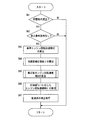
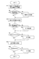
図11において、SE1では、本ルーチンの実行の前提となる実行条件が成立したか否かが判断される。この実行条件とは、たとえば、スロットル開度θthが全開(たとえば100%またはその近傍の値)であり、油温Toilが所定値以上の自動変速機暖機状態であり、エンジン水温Twが所定値以上のエンジン暖機状態であり、エンジン回転速度センサなどが正常であり、全開アップ変速に関与する油圧式摩擦係合装置が正常であることである。上記SE1の判断が否定される場合はその状況において変速が実行されても、その際の変速点の学習については実行されず、本フローチャートは終了する。正常な状態における変速ではなく、誤学習となるためである。一方、SE1の判断が肯定される場合は、続くSE2以降が実行される。 In FIG. 11, in SE1, it is determined whether or not an execution condition that is a precondition for executing this routine is satisfied. The execution condition is, for example, an automatic transmission warm-up state in which the throttle opening θth is fully open (for example, 100% or a value close thereto), the oil temperature Toil is a predetermined value or more, and the engine water temperature Tw is a predetermined value. The engine warm-up state is as described above, the engine speed sensor and the like are normal, and the hydraulic friction engagement device involved in the full-open upshift is normal. If the determination of SE1 is negative, even if a shift is executed in that situation, the learning of the shift point at that time is not executed, and this flowchart ends. This is because it is not a shift in a normal state but erroneous learning. On the other hand, when the determination of SE1 is affirmed, subsequent SE2 and subsequent steps are executed.
続くSE2およびSE3は、車両加速度変動検出手段102に対応する。このうち、加速度フィルタ処理手段140に対応するSE2においては、図12に示す車両加速度フィルタ処理ルーチンが実行される。図12の車両加速度フィルタ処理ルーチンにおいては、SF1において、まず車両加速度aが算出される。具体的には、駆動輪に設けられた回転速度センサやトルクコンバータのタービン14tの回転速度センサによって計測された値から車速Vを算出し、算出された車速Vの微小単位時間あたりの変化量dV/dt(=(V(t+Δt)−V(t))/Δt)を算出することなどによって算出される。
The subsequent SE2 and SE3 correspond to the vehicle acceleration
続いてSF2においては、SF1において算出された車両加速度aを例えば高速フーリエ変換することなどによって、フィルタ処理を行い、特定の周波数成分を除去するなどした処理後の車両加速度asが算出される。 Subsequently, in SF2, the vehicle acceleration “as” after processing such as filtering processing is performed by, for example, performing fast Fourier transform on the vehicle acceleration “a” calculated in SF1 and the specific frequency component is removed is calculated.
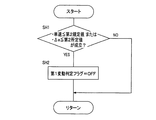
図11に戻って、第1変動検出手段146、第2変動検出手段148および変動検出判定手段150に対応するSE3においては、図13乃至図19に示す各ルーチンが実行される。図13および図14のルーチンは第1変動検出手段146に対応するものであって、図13が前記第1変動検出条件を満たすか否かの判定に用いられる一方、図14は例えば図13のルーチンの実行後に実行され、前記第1変動検出解除条件を満たすか否かの判定に用いられる。 Returning to FIG. 11, in SE3 corresponding to the first fluctuation detecting means 146, the second fluctuation detecting means 148, and the fluctuation detection determining means 150, the routines shown in FIGS. 13 to 19 are executed. The routines of FIGS. 13 and 14 correspond to the first fluctuation detection means 146, and FIG. 13 is used to determine whether or not the first fluctuation detection condition is satisfied. On the other hand, FIG. It is executed after execution of the routine, and is used to determine whether or not the first fluctuation detection cancellation condition is satisfied.
図13のSG1においては、前提条件として、車速Vが前記第1規定値以上であること、かつ、変速中でないことが満たされるか否かが判断される。そして、本判断が肯定される場合には続くSG2が実行される。一方、本判断が否定される場合には、前提条件を満たさないとして、第1変動判定フラグがオンにされることなく、本ルーチンは終了される。 In SG1 of FIG. 13, it is determined as a precondition whether the vehicle speed V is equal to or higher than the first specified value and that the gear is not being shifted is satisfied. If this determination is affirmative, the subsequent SG2 is executed. On the other hand, if this determination is negative, the routine is terminated without turning on the first fluctuation determination flag because the precondition is not satisfied.
SG2においては、実際の車両加速度aと前記フィルタ処理後の車両加速度asの偏差Δa(=|a−as|)が前記第1所定値以上であるか否かが判断される。そして、本判断が肯定された場合には、前記第1変動検出条件を満たしたとして、SG3において第1変動判定フラグがオンとされ、本ルーチンが終了される。一方、本判断が否定された場合には、第1変動判定フラグがオンにされることなく本ルーチンが終了される。 In SG2, it is determined whether or not a deviation Δa (= | a−as |) between the actual vehicle acceleration a and the filtered vehicle acceleration as is equal to or greater than the first predetermined value. If this determination is affirmative, it is determined that the first variation detection condition is satisfied, the first variation determination flag is turned on in SG3, and this routine is terminated. On the other hand, if this determination is negative, the present routine is terminated without turning on the first variation determination flag.
図14のSH1においては、車速Vが前記第2規定値以下であること、あるいは、前記偏差Δaが第2所定値以下であることの第1変動検出解除条件を満たすか否かが判断される。そして、本ステップの判断が肯定される場合には、続くSH2において前記第1変動判定フラグがオフとされる。一方、本ステップの判断が否定される場合には、第1変動判定フラグの内容が変更されることなく、本ルーチンは終了される。 In SH1 of FIG. 14, it is determined whether or not the vehicle speed V is less than or equal to the second specified value, or whether or not the first fluctuation detection cancellation condition is satisfied that the deviation Δa is less than or equal to a second predetermined value. . If the determination in this step is affirmative, the first fluctuation determination flag is turned off in the subsequent SH2. On the other hand, if the determination in this step is negative, the routine ends without changing the content of the first fluctuation determination flag.
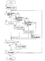
図15乃至17は、前記第2変動検出手段148に対応するものである。このうち、図15は、前記変動判定カウンタの処理に用いられるものである。図15のSI1においては、本ルーチンの実行にあたり、変動判定カウンタCの値がリセットすなわち零とされる。
FIGS. 15 to 17 correspond to the second
続くSI2においては、自動変速機16の変速段が規定の変速段よりも高速側の変速段であり、かつ、変速終了直後であるか否かを判断し、その判断が肯定される場合には、続くSI3において変速後の変速段について新たにカウントを開始すべく変動判定カウンタCをリセット(C=0)する。一方、SI2の判断が否定される場合には、それまでの変動判定カウンタCの値を保持したまま、続くSI4以降が実行される。なお、前記規定の変速段とは、前記第2変動検出手段148で検出の対象とする小〜中規模の変動が生じ得る走行状態となる変速段においてSI2の判断が肯定される様に予め実験的にあるいはシミュレーション等により、例えば第4速段とそれよりも高速側の変速段での走行を対象として変動判定カウンタの処理を行なう場合には前記規定の変速段が第3速段のように決定される。
In the subsequent SI2, it is determined whether or not the shift stage of the
SI4においては、車速Vが前記第5規定値以上であり、変速中でなく、偏差Δaが前記第5所定値以上であることの全てを満たすか否かが判断される。そして、SI4の判断が肯定される場合には、続くSI5において変動判定カウンタCの値に1が加えられる。一方、本ステップの判断が否定される場合には、それまでの変動判定カウンタCの値を保持したまま続くSI6以降が実行される。 In SI4, it is determined whether or not the vehicle speed V is equal to or higher than the fifth specified value, the shift is not being performed, and the deviation Δa is all equal to or higher than the fifth predetermined value. When the determination of SI4 is affirmed, 1 is added to the value of the fluctuation determination counter C in the subsequent SI5. On the other hand, if the determination in this step is negative, SI6 and subsequent steps are executed while maintaining the value of the fluctuation determination counter C so far.
SI6においては、車速Vが前記第5規定値以上であり、変速中でなく、偏差Δaが前記第5所定値未満であることの全てを満たすか否かが判断される。そして、SI6の判断が肯定される場合には、続くSI7において変動判定カウンタCの値から1を減じられる。一方、本ステップの判断が否定される場合には、SI8においてそれまでの変動判定カウンタCの値を保持したまま、続くSI9以降が実行される。 In SI6, it is determined whether or not the vehicle speed V is greater than or equal to the fifth specified value, the shift is not being performed, and the deviation Δa is less than the fifth predetermined value. When the determination of SI6 is affirmed, 1 is subtracted from the value of the fluctuation determination counter C in the subsequent SI7. On the other hand, if the determination in this step is negative, the subsequent SI9 and subsequent steps are executed while the value of the variation determination counter C is maintained in SI8.
SI9においては、SI1乃至SI8が実行された結果、得られた変動判定カウンタCの値がCmin≦C≦Cmaxを満たすか否かが判断される。そして本判断が肯定される場合には、得られた変動判定カウンタCの値を結果として、SI11が実行される。一方、SI9の判断が否定される場合には、続くSI10において、変動判定カウンタCの値がC>Cmaxの場合にはC=Cmax、C<Cminの場合にはC=Cminとする、いわゆるガード処理が実行される。このガード処理のうち、その下限については、いわゆる下限側のガード値Cminが例えばCmin=0とされ、変動判定カウンタCが負の値をとることがないようにされる。また、上限については、後述する第2変動検出手段148によって第2変動検出解除条件を満たすかが判断される際(具体的には後述する図17のフローチャートにおけるSK1がこれに該当する)において、変動判定カウンタCの値が大きくなりすぎてしまい、第2変動検出解除条件が満たされるのに時間を要するという問題を回避するために行なわれる。したがって、上限側のガード値Cmaxは、第2変動検出条件が満たされ学習補正値調整手段100による学習補正値の調整が開始されてから、第2変動検出解除条件が満たされ学習補正値調整手段100による学習補正値の調整から終了するまでの間の設計上最大の時間などに基づいて決定される。具体的には、例えば、第2変動検出条件が満たされ学習補正値調整手段100による学習補正値の調整が開始されてから、第2変動検出解除条件が満たされ学習補正値調整手段100による学習補正値の調整から終了するまでの時間を最大2000msとなるように設計する場合であって、本図15のルーチンが10msの周期で実行される場合には、例えばCmax=200のように決定される。
In SI9, it is determined whether or not the value of the fluctuation determination counter C obtained as a result of executing SI1 to SI8 satisfies Cmin ≦ C ≦ Cmax. If this determination is affirmative, SI11 is executed with the value of the obtained fluctuation determination counter C as a result. On the other hand, if the determination of SI9 is negative, in the subsequent SI10, if the value of the fluctuation determination counter C is C> Cmax, C = Cmax, and if C <Cmin, C = Cmin, so-called guard. Processing is executed. Among the guard processes, for the lower limit, the so-called lower limit guard value Cmin is set to Cmin = 0, for example, so that the fluctuation determination counter C does not take a negative value. As for the upper limit, when it is determined by the second fluctuation detecting means 148 described later whether the second fluctuation detection cancellation condition is satisfied (specifically, SK1 in the flowchart of FIG. 17 described later corresponds to this), This is performed to avoid the problem that the value of the fluctuation determination counter C becomes too large and it takes time to satisfy the second fluctuation detection cancellation condition. Therefore, the upper limit guard value Cmax is satisfied after the second variation detection condition is satisfied and the learning correction
SI11においては、本ルーチンの実行が開始から所定時間だけ行われたか否かが判断される。本判断が肯定される場合、すなわち、本ルーチンが前記所定時間だけ実行された場合には、本ルーチンを終了する。一方、本ステップの判断が否定される場合、すなわち、本ルーチンの実行が前記所定時間に満たない場合には、前記所定時間が経過するまで、すなわち本ステップの判断が肯定されるまでの間SI2乃至SI10が反復されるべく、SI2に戻る。なお、前記所定時間とは、第2変動検出手段148が加速度の変動を検出するために十分な時間として予め実験的にあるいはシミュレーションにより算出される。 In SI11, it is determined whether or not this routine has been executed for a predetermined time from the start. If this determination is affirmative, that is, if this routine is executed for the predetermined time, this routine is terminated. On the other hand, if the determination in this step is negative, that is, if the execution of this routine is less than the predetermined time, SI2 is continued until the predetermined time elapses, that is, until the determination in this step is affirmed. Return to SI2 so that SI10 is repeated. The predetermined time is calculated in advance experimentally or by simulation as a sufficient time for the second fluctuation detecting means 148 to detect a fluctuation in acceleration.
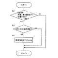
図16及び図17は、第2変動検出手段148に対応するものであって、図16が前記第2変動検出条件を満たすか否かの判定に用いられる一方、図17は例えば図16のルーチンの実行後に実行され、前記第2変動検出解除条件を満たすか否かの判定に用いられる。 FIGS. 16 and 17 correspond to the second variation detecting means 148, and FIG. 16 is used to determine whether or not the second variation detection condition is satisfied. On the other hand, FIG. And is used to determine whether or not the second variation detection cancellation condition is satisfied.
図16のSJ1においては、前提条件として、車速Vが前記第3規定値以上であること、かつ、変速中でないことが満たされるか否かが判断される。そして、本判断が肯定される場合には続くSJ2が実行される。一方、本判断が否定される場合には、前提条件を満たさないとして、第2変動判定フラグがオンにされることなく、本ルーチンは終了される。 In SJ1 of FIG. 16, it is determined as a precondition whether the vehicle speed V is equal to or higher than the third specified value and that the vehicle is not shifting. If this determination is affirmed, the subsequent SJ2 is executed. On the other hand, if this determination is negative, it is determined that the precondition is not satisfied, and this routine is terminated without turning on the second variation determination flag.
SJ2においては、図15のルーチンによって算出された変動判定カウンタCの値が前記第3所定値以上であるか否かが判断される。そして、本判断が肯定された場合には、前記第2変動検出条件を満たしたとしてSJ3において第2変動判定フラグがオンとされ、本ルーチンが終了される。一方、本判断が否定された場合には、第2変動判定フラグがオンにされることなく本ルーチンが終了される。 In SJ2, it is determined whether or not the value of the fluctuation determination counter C calculated by the routine of FIG. 15 is greater than or equal to the third predetermined value. If this determination is affirmative, the second fluctuation determination flag is turned on in SJ3 because the second fluctuation detection condition is satisfied, and this routine is terminated. On the other hand, if the determination is negative, the routine ends without turning on the second variation determination flag.
図17のSK1においては、車速Vが前記第4規定値以下であること、あるいは、前記変動判定カウンタCの値が前記第4所定値以下であることの第2変動検出解除条件を満たすか否かが判断される。そして、本ステップの判断が肯定される場合には、続くSK2において前記第2変動判定フラグがオフとされる。一方、本ステップの判断が否定される場合には、第2変動判定フラグの内容が変更されることなく、本ルーチンは終了される。 In SK1 of FIG. 17, whether or not the second fluctuation detection cancellation condition that the vehicle speed V is less than or equal to the fourth specified value or that the value of the fluctuation determination counter C is less than or equal to the fourth predetermined value is satisfied. Is judged. If the determination in this step is affirmative, the second fluctuation determination flag is turned off in the subsequent SK2. On the other hand, if the determination at this step is negative, the routine ends without changing the content of the second variation determination flag.
図18及び図19は、変動検出判定手段150に対応するものであって、図18が前記変動判定条件を満たすか否かの判定に用いられる一方、図17は例えば図16のルーチンの実行後に実行され、前記変動判定解除条件を満たすか否かの判定に用いられる。 18 and FIG. 19 correspond to the fluctuation detection determination means 150, and FIG. 18 is used to determine whether or not the fluctuation determination condition is satisfied, while FIG. 17 shows, for example, after the execution of the routine of FIG. It is executed and used to determine whether or not the variation determination cancellation condition is satisfied.
図18のSL1においては、図13および図14のルーチンによって決定された第1変動判定フラグの内容がオンであるか否かが判断される。そして、本判断が肯定される場合、すなわち第1変動判定フラグがオンである場合にはSL3が実行される。一方、本SL1の判断が否定される場合、すなわち第2変動判定フラグがオフである場合には、続くSL2が実行される。 In SL1 of FIG. 18, it is determined whether or not the content of the first variation determination flag determined by the routines of FIGS. 13 and 14 is on. When this determination is affirmative, that is, when the first variation determination flag is on, SL3 is executed. On the other hand, when the determination of this SL1 is negative, that is, when the second variation determination flag is OFF, the subsequent SL2 is executed.
SL2においては、図16及び図17のルーチンによって決定された第2変動判定フラグの内容がオンであるか否かが判断される。そして、本判断が肯定される場合、すなわち、第2変動判定フラグがオンである場合にはSL3が実行される。一方、本SL2の判断が否定される場合、すなわち第2変動判定フラグがオフである場合には、SL4が実行される。 In SL2, it is determined whether or not the content of the second variation determination flag determined by the routines of FIGS. 16 and 17 is ON. If this determination is affirmative, that is, if the second variation determination flag is on, SL3 is executed. On the other hand, when the determination of this SL2 is negative, that is, when the second variation determination flag is off, SL4 is executed.
SL3においては、第3変動判定フラグがオンとされる。一方SL4においては第3変動判定フラグがオフとされる。すなわち、図18のルーチンにおいては、前記第1変動判定フラグと第2変動判定フラグの少なくとも一方がオンであれば第3変動判定フラグをオンとする一方、第1変動判定フラグと第2変動判定フラグがともにオフである場合には第3変動判定フラグをオフとする作動を行っている。 In SL3, the third variation determination flag is turned on. On the other hand, in SL4, the third variation determination flag is turned off. That is, in the routine of FIG. 18, if at least one of the first variation determination flag and the second variation determination flag is on, the third variation determination flag is turned on, while the first variation determination flag and the second variation determination are performed. When both of the flags are off, the third fluctuation determination flag is turned off.
一方図19のSM1においては、第1変動判定フラグがオフであるか否かが判断される。そして本判断が肯定される場合、すなわち第1変動判定フラグがオフである場合には続くSM2が実行される。一方本SM1の判断が否定される場合、すなわち第1変動判定フラグがオンである場合には、以前の第3変動判定フラグの値を保持したまま本ルーチンを終了する。 On the other hand, in SM1 of FIG. 19, it is determined whether or not the first variation determination flag is OFF. If this determination is affirmative, that is, if the first variation determination flag is OFF, the subsequent SM2 is executed. On the other hand, if the determination of this SM1 is negative, that is, if the first variation determination flag is on, this routine is terminated while retaining the previous value of the third variation determination flag.
SM2においては、第2変動判定フラグがオフであるか否かが判断される。そして本判断が肯定される場合、すなわち第2変動判定フラグがオフである場合には続くSM3が実行される。一方本SM2の判断が否定される場合、すなわち第2変動判定フラグがオンである場合には、以前の第3変動判定フラグの値を保持したまま本ルーチンを終了する。 In SM2, it is determined whether or not the second variation determination flag is off. If this determination is affirmative, that is, if the second variation determination flag is OFF, the subsequent SM3 is executed. On the other hand, if the determination of this SM2 is negative, that is, if the second variation determination flag is on, this routine is terminated while the previous value of the third variation determination flag is retained.
SM3においては、第3変動判定フラグの値がオフとされる。すなわち、本図19のルーチンにおいては、第1変動判定フラグ、第2変動判定フラグが共にオフである時のみ第3変動判定フラグの値をオフとする一方、第1変動判定フラグおよび第2変動判定フラグの少なくとも何れか一方がオンである場合には従前の値を保持する作動を行っている。そして、前記第3変動判定フラグの値を決定することにより、図13乃至図19の一連のルーチンの実行が完了する。 In SM3, the value of the third variation determination flag is turned off. That is, in the routine of FIG. 19, the value of the third variation determination flag is turned off only when both the first variation determination flag and the second variation determination flag are off, while the first variation determination flag and the second variation determination flag. When at least one of the determination flags is on, an operation for holding the previous value is performed. Then, by determining the value of the third variation determination flag, execution of a series of routines of FIGS. 13 to 19 is completed.
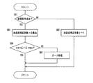
図11に戻って、前記基準エンジン回転加速度算出手段74に対応するSE4においては、基準エンジン回転加速度A2が算出される。すなわち、SE4では、変速出力時点における車両の走行状態、たとえば車速V、スロットル開度θth、自動変速機16の入力トルクTinの少なくとも1つに基づいて、予め実験的に求められ、かつ記憶された関係から、基準エンジン回転加速度A2が算出される。
Returning to FIG. 11, in SE4 corresponding to the reference engine rotational acceleration calculating means 74, the reference engine rotational acceleration A2 is calculated. That is, in SE4, it is experimentally obtained and stored in advance based on at least one of the vehicle running state at the time of shifting output, for example, vehicle speed V, throttle opening θth, and input torque Tin of
推定最大エンジン回転速度算出手段72に対応するSE5においては、推定最大エンジン回転速度NEcの値が推定される。すなわち、SE5においては、SE4において算出された基準エンジン回転加速度A2、エンジン回転速度センサ46により検出された変速出力時点におけるエンジン12の回転速度NE1、イナーシャ相開始時点におけるエンジン12の回転速度NE2、および検出されたエンジン回転速度NEからエンジン回転加速度算出手段76により逐次算出されるエンジン回転加速度のうち変速出力時点のエンジン回転加速度A1を、前述の式(1)に適用することにより推定最大エンジン回転速度NEcの値が推定される。なお、上述の通り、通常、エンジン回転速度NEは変動(ノイズ)が大きいので、その移動平均などの平滑化フィルタ処理後のエンジン回転速度NEが用いられる。
In SE5 corresponding to the estimated maximum engine speed calculating means 72, the value of the estimated maximum engine speed NEc is estimated. That is, in SE5, the reference engine rotational acceleration A2 calculated in SE4, the rotational speed NE1 of the
続くSE6は、学習補正値算出手段80に対応する。SE6においては、図20に示す学習ルーチンが実行される。図20において、SN1では、SE5で推定された推定最大エンジン回転速度NEcと、予め設定された目標最大エンジン回転速度NEdとの偏差ΔNE1が算出される。 The subsequent SE 6 corresponds to the learning correction value calculation means 80. In SE6, the learning routine shown in FIG. 20 is executed. In SN1, in SN1, a deviation ΔNE1 between the estimated maximum engine speed NEc estimated in SE5 and a preset target maximum engine speed NEd is calculated.
SN2乃至SN3は、学習ゲイン調整手段140に対応する。まず、SN2においては、第1乃至第3変動判定フラグの少なくともいずれか1つがオンであるか否かを判断することにより、車両加速度変動検出手段102によって車両加速度aの変動が検出されたか否かを判断する。そして、本判断が肯定、すなわち第1乃至第3変動判定フラグの少なくともいずれか1つがオンである場合には、続くSN3において、学習補正値算出手段80において用いられる学習ゲインKの値が、エンジン回転加速度の変動を検出しない場合に比べて小さい値K’とされる。一方、SN2の判断が否定される場合、すなわち第1乃至第3変動判定フラグの全てがオフである場合には、SN3が実行されることなく、SN4が実行される。 SN2 to SN3 correspond to the learning gain adjusting means 140. First, in SN2, whether or not a change in the vehicle acceleration a is detected by the vehicle acceleration change detection means 102 by determining whether or not at least one of the first to third change determination flags is on. Judging. If the present determination is affirmative, that is, if at least one of the first to third variation determination flags is on, the value of the learning gain K used in the learning correction value calculation means 80 in the subsequent SN3 is the engine. The value K ′ is smaller than that in the case where no change in rotational acceleration is detected. On the other hand, when the determination of SN2 is negative, that is, when all of the first to third variation determination flags are off, SN4 is executed without executing SN3.
続いて、SN4では、SN1で算出された偏差ΔNE1に基づき、1回あたりの変速点学習量ΔGが決定される。ここでΔGは、ΔG=K×ΔNE1なる関係によって求められる。但しKは学習の重みを決定する学習補正係数(学習ゲイン)であって、予め与えられている。なお、前記SN3が実行された場合には、学習ゲインKに替えてSN3において算出されたK’が用いられる。 Subsequently, at SN4, the shift point learning amount ΔG per time is determined based on the deviation ΔNE1 calculated at SN1. Here, ΔG is obtained by the relationship ΔG = K × ΔNE1. Here, K is a learning correction coefficient (learning gain) for determining the learning weight and is given in advance. When SN3 is executed, K ′ calculated at SN3 is used instead of the learning gain K.
SN5乃至SN6はガード値調整手段142に対応する。まず、SN5においては、SN2と同様に第1乃至第3変動判定フラグの少なくともいずれか1つがオンであるか否かを判断することにより、車両加速度変動検出手段102によって車両加速度aの変動が検出されたか否かを判断する。そして、本判断が肯定、すなわち第1乃至第3変動判定フラグの少なくともいずれか1つがオンである場合には、続くSN6において、補正値制限手段82において用いられるいわゆるガード値ΔGmaxおよびΔGminの値が、それぞれエンジン回転加速度の変動を検出しない場合に比べて小さい値ΔGmax’およびΔGmin’とされる。一方、SN5の判断が否定される場合、すなわち第1乃至第3変動判定フラグの全てがオフである場合には、SN6が実行されることなく、SN6が実行される。
SN5 to SN6 correspond to the guard
続くSN7及びSN8は、補正値制限手段82に対応する。まず、SN7においては、SN4で決定された1回あたりの学習量ΔGが予め定められた範囲(ΔGmin≦ΔG≦ΔGmax)を超えていないか否かが判定され、前記範囲を超えている場合には、ΔGの値を制限すべく、SN8が実行される。一方、SN7の判定が肯定される場合は決定されたΔGをそのまま学習に用いるものとして、ΔG’=ΔGとして、SN10に移る。SN8においては、ΔGが前記範囲の上限ΔGmaxを上回っている場合にはΔG=ΔGmaxとし、ΔGが前記範囲の下限ΔGminを下回っている場合にはΔG=ΔGminとする、ガード処理を行う。なお、前記SN6が実行された場合には、ガード値ΔGmax,ΔGminに替えてSN6において算出されたΔGmax’およびΔGmin’がそれぞれ用いられる。
The subsequent SN 7 and SN 8 correspond to the correction
SN9では、このようにして算出されたΔG’を前回の変速時までの全体学習量G(N−1)に加える事により、今回の変速における学習を加えた全体学習量G(N)とする。すなわち、今回の学習後の全体学習量G(N)は、G(N)=G(N−1)+ΔG’で表される。 At SN9, ΔG ′ calculated in this way is added to the total learning amount G (N−1) until the previous shift, thereby obtaining the total learning amount G (N) obtained by learning in the current shift. . That is, the total learning amount G (N) after the current learning is represented by G (N) = G (N−1) + ΔG ′.
続くSN10及びSN11は、補正値制限手段82に対応する。すなわち、SN10では、算出された全体学習量G(N)について、予め定められた範囲(Gmin≦G(N)≦Gmax)を超えていないかを判定し、SN10の判断が否定された場合、すなわち前記範囲を超えている場合には、SN11へ進む一方、SN10の判断が肯定された場合には、SN10において算出された全体学習量G(N)を学習結果として、本ルーチンは終了する。SN11においては、G(N)が前記範囲の上限Gmaxを上回っている場合にはG(N)=Gmaxとし、G(N)が前記範囲の下限Gminを下回っている場合にはG(N)=Gminとする、ガード処理を行い、それぞれの処理後のG(N)を学習結果として、本ルーチンは終了する。
The subsequent SN 10 and SN 11 correspond to the correction
図11に戻って、変速点補正手段84に対応するSE7においては、SE6(図11)の学習ルーチンの終了に伴って得られた学習後の全体学習量G(N)にもとづいて、変速線図記憶手段52に記憶された変速線図が補正され、本フローチャートは終了する。 Returning to FIG. 11, in SE7 corresponding to the shift point correcting means 84, the shift line is based on the learned total learning amount G (N) obtained along with the end of the learning routine in SE6 (FIG. 11). The shift map stored in the figure storage means 52 is corrected, and this flowchart ends.
図21および図22は、第1速段から第2速段への(1→2)全開アップ変速時のエンジン回転速度NEの時間変化を表す図であって、図21は、本発明の実施例の適用がない場合、図22は本発明の実施例が適用された場合をそれぞれ表している。 FIG. 21 and FIG. 22 are diagrams showing the time change of the engine rotation speed NE at the time of (1 → 2) fully open upshift from the first speed to the second speed, and FIG. 21 shows the implementation of the present invention. When the example is not applied, FIG. 22 shows the case where the embodiment of the present invention is applied.
まず、図21について説明する。従来、変速点補正手段70による自動変速機のばらつきに応じた変速点の学習補正が行われない場合、変速点におけるエンジン回転速度がNEpであるように設定されている。そして、図21における実線110の勾配が表すエンジン回転加速度で走行していた車両は、時刻t11において、エンジン回転速度NEが前記NEpを超え、アップ変速出力が開始される。すると、時刻t13において、イナーシャ相が開始され、エンジン回転速度は下降する(破線112)。このとき、エンジン回転速度NEは目標最大エンジン回転速度NEdに達することがなく、十分にエンジンの性能を使い切っていない。このような変速が変速点補正手段70によって学習され、変速点は、エンジン回転速度NEがNEoとなるように補正される。その結果、前記実線110の勾配が表すエンジン回転加速度で走行していた車両は、時刻t12において、エンジン回転速度NEが前記NEoを超え、アップ変速出力が開始されることとなる。そして、時刻t15において、イナーシャ相が開始され、そのときのエンジン回転速度NEのピークは目標最大エンジン回転速度NEdに接近し、エンジンの回転速度域を十分に使い切ることができる。
First, FIG. 21 will be described. Conventionally, when the learning correction of the shift point according to the variation of the automatic transmission by the shift point correction means 70 is not performed, the engine speed at the shift point is set to NEp. Then, the vehicle running at the engine rotational acceleration represented by the gradient of the
しかしながら、かかる変速点補正手段70による変速点の補正は、自動変速機のばらつきに応じたものであって、車両の加速度に応じたものではないことから、学習時の加速度とは異なる加速度において前記全開アップ変速が行われる場合、たとえば、図21において点線116の勾配で示されるような高加速度による走行時には、イナーシャ相開始時までのエンジン回転速度NEの変化において、そのエンジン回転速度NEが目標最大エンジン回転速度NEdを超えてしまうことがあり、逆に、図21において太線114の勾配で示されるような低下速度による走行時には、エンジン回転速度NEが目標最大エンジン回転速度NEdに達することがないままイナーシャ相が開始されてしまうことがある。
However, since the shift point correction by the shift
一方、本発明の実施例が適用された図22によると、アップ変速判断時t20においてエンジン回転加速度Aおよび基準エンジン回転加速度A2が算出され、また、それらの比である加速度補正係数γが算出され、算出された加速度補正係数γに基づいて、変速点補正手段70によて学習補正され、変速線図記憶手段52に記憶された補正後の変速点が修正される結果、変速実行時の加速度がばらつく場合であっても、変速出力後イナーシャ相開始までのエンジン回転速度NEの変化が、目標最大エンジン回転速度NEdに接近するようにされる。
On the other hand, according to FIG. 22 to which the embodiment of the present invention is applied, the engine rotational acceleration A and the reference engine rotational acceleration A2 are calculated at the upshift determination time t20, and the acceleration correction coefficient γ, which is the ratio between them, is calculated. Based on the calculated acceleration correction coefficient γ, learning correction is performed by the shift
すなわち、図22において、実線118で表された、加速度補正係数γ=1、すなわちアップ変速判断時t20におけるエンジン回転加速度A2が基準エンジン回転加速度Aと等しい場合においては、変速点は変速点補正手段70によって学習補正されたエンジン回転速度がNEoに対応する変速点から修正がされない。したがって、時刻t22においてエンジン回転速度NEがNEoを超え、変速出力が開始され、また、その後時刻t24においてイナーシャ相が開始されるまでに、エンジン回転速度NEは、目標最大エンジン回転速度NEdに接近する。
That is, in FIG. 22, when the acceleration correction coefficient γ = 1 represented by the
また、点線122で表された、加速度補正係数γ>1、すなわち、アップ変速判断時t20におけるエンジン回転加速度A2が基準エンジン回転加速度Aよりも大きい高加速度時においては、変速点は変速点補正手段70によって学習補正されたエンジン回転速度がNEoに対応する変速点から、エンジン回転速度がNEn’2に対応する変速点に修正がされる。その結果、時刻t21において、エンジン回転速度NEがNEn’2を超えて変速出力が開始され、また、その後時刻t24においてイナーシャ相が開始されるまでにエンジン回転速度NEが目標最大エンジン回転速度NEdに接近する。一方、太線120で示された、加速度補正係数γ<1、すなわち、アップ変速判断時t20におけるエンジン回転加速度A2が基準エンジン加速度Aよりも小さい低加速度時においては、変速点は変速点補正手段70によって学習補正されたエンジン回転速度がNEoに対応する変速点から、エンジン回転速度がNEn’1に対応する変速点に修正がされる。その結果、時刻t23においてエンジン回転速度NEがNEn’1を超えて変速出力が開始され、また、その後時刻t24においてイナーシャ相が開始されるまでにエンジン回転速度NEが目標最大エンジン回転速度NEdに接近する。
Further, when the acceleration correction coefficient γ> 1 represented by the dotted
尚、図22において、アップ変速判断時t20は、変速点の修正によって、変速出力開始時が基準加速度A2における走行時(t22)よりも早まる可能性を考慮して設定される。たとえば、車両が基準加速度A2で走行する場合における変速時t22から、変速点の修正によって最大で例えばt21まで変速時が早まる可能性がある場合には、少なくとも、時刻t21から、さらに変速判断やそれに伴う計測や計算の処理に要する時間だけ早まった時刻と設定されれば良い。このとき、変速点の修正にあたり、修正する変速点に対応するエンジン回転速度はガード処理がなされ、その下限NEnminが設けられていることから、そのエンジン回転速度と、想定し得る車両の加速度に応じて変速出力開始時が最も早まる場合の時刻を算出し得る。 In FIG. 22, the upshift determination time t20 is set in consideration of the possibility that the shift output start time may be earlier than the travel time (t22) at the reference acceleration A2 due to the shift point correction. For example, if there is a possibility that the shift time may be accelerated up to t21, for example, at the maximum from the shift time t22 when the vehicle travels at the reference acceleration A2 by correction of the shift point, at least from time t21, the shift determination and further It is only necessary to set a time that is earlier by the time required for the associated measurement and calculation processing. At this time, when the shift point is corrected, the engine speed corresponding to the shift point to be corrected is guarded, and the lower limit NEMmin is provided, so that it depends on the engine rotation speed and the assumed acceleration of the vehicle. Thus, the time when the shift output start time is the earliest can be calculated.
以上の実施例によれば、変速点リアルタイム修正手段60においては、変速点補正手段70によって変速出力後においても所定期間上昇するエンジン回転速度NEの最大値が目標最大エンジン回転速度NEdに接近するように変更された変速点が、エンジン回転加速度算出手段(76・SA3)によって算出されたパワーオン走行時でのアップ変速判断時点の実際のエンジン回転加速度の値Aと、基準エンジン回転加速度算出手段(74・SA3)によって算出された、実際のエンジン回転加速度の値を車両の加速度に影響しない基準走行状態における値に置換した基準エンジン回転加速度A2との比の値である、加速度補正係数算出手段(90・SA4)によって算出された加速度補正係数γと、目標最大エンジン回転速度NEdとに基づいて修正後エンジン回転速度算出手段(92・SA5)によって修正後の変速点に対応するエンジン回転速度が算出され、変速点修正実行手段(94・SA7)によってリアルタイムで変速点が修正されることから、実際のエンジン回転加速度を考慮したタイミングで変速指示を行うことができ、原動機の回転加速度Aが基準回転加速度A2と異なる場合、すなわち、車両の加速度に影響を与える牽引(トーイング)時や、登坂路走行時といった走行条件においても、エンジン回転速度NEを目標最大エンジン回転速度NEdに近づけることができる。
According to the above embodiment, in the shift point real-
また、上述の実施例によれば、変速点リアルタイム修正手段60においては、基準エンジン回転加速度算出手段(74・SA3)によって、パワーオン走行時でのアップ変速判断時のエンジン回転加速度の値Aを、車両の加速度に影響しない基準走行状態における値に置換した基準エンジン回転加速度A2を算出するため、基準エンジン回転加速度A2とアップ変速判断時のエンジン回転加速度との比の値に基づいて補正値をさらに修正するので、牽引(トーイング)時や登坂路走行時のように車両の加速度が通常状態と異なる場合においても、加速度の大きさに応じた変速点の修正を行うことができる。
Further, according to the above-described embodiment, the shift point real-
また、上述の実施例によれば、特に変速中の最大エンジン回転速度NEが目標最大エンジン回転速度に追従することが必要とされるWOT(Wide Open Throttle;全開)変速時において、エンジン回転速度NEが目標最大エンジン回転速度NEdに精度よく追従することが可能となり、エンジン回転速度NEが目標最大エンジン回転速度NEdに到達することなくアップシフトが実行される現象や、エンジン回転速度NEが許容される最大のエンジン回転速度を超過した状態が継続したままアップシフトが行われる現象の発生を抑止することが可能となり、上記減少に伴う使用者の違和感を低減することができる。 In addition, according to the above-described embodiment, the engine speed NE is changed particularly at the time of WOT (Wide Open Throttle) shift in which the maximum engine speed NE during the shift needs to follow the target maximum engine speed. Can accurately follow the target maximum engine speed NEd, and an upshift is performed without the engine speed NE reaching the target maximum engine speed NEd, and the engine speed NE is allowed. It is possible to suppress the occurrence of a phenomenon in which an upshift is performed while the state where the maximum engine speed is exceeded continues, and it is possible to reduce the user's uncomfortable feeling due to the above reduction.
また、上述の実施例によれば、変速点補正手段(70・SC1)は、パワーオン走行時でのアップ変速出力後のエンジン回転速度NEの最大値を車両の加速度に影響しない基準走行状態における値に置換した推定最大エンジン回転速度を推定し、該推定最大エンジン回転速度と目標最大エンジン回転速度NEdとの偏差に基づいて算出した補正値に基づいて補正された変速点について、変速点リアルタイム修正手段60が補正値をリアルタイムで修正するので、自動変速機のばらつきに応じた変速点の補正に加え、車両の加速度Aのばらつきに応じた変速点の修正をも行うことができる。
Further, according to the above-described embodiment, the shift point correcting means (70 · SC1) is in the reference running state in which the maximum value of the engine rotational speed NE after the upshift output during the power-on running does not affect the vehicle acceleration. The estimated maximum engine speed replaced with the value is estimated, and the shift point corrected based on the correction value calculated based on the deviation between the estimated maximum engine speed and the target maximum engine speed NEd is corrected in real time. Since the
また、上述の実施例によれば、変速点補正手段(70・SC1)は車両加速度変動検出手段(102・SE3)によって検出された車両の加速度aの変動の大きさに基づいて補正値を調整するので、車両の加速度aの変動が生じた場合であっても、前記変速点補正手段による変速点の学習や、変速点の補正を中断することなく誤学習の影響を抑制しつつ継続することができる。 Further, according to the above-described embodiment, the shift point correcting means (70 · SC1) adjusts the correction value based on the magnitude of the fluctuation of the vehicle acceleration a detected by the vehicle acceleration fluctuation detecting means (102 · SE3). Therefore, even when the fluctuation of the acceleration a of the vehicle occurs, the shift point correction means by the shift point correction means and the correction of the shift point are not interrupted and are continued while suppressing the influence of erroneous learning. Can do.
また、上述の実施例によれば、変速点補正手段(70・SC1)による補正値の調整は、加速度変動検出手段(102・SE3)によって検出された車両の加速度aの変動の大きさが大きいほど、車両加速度の変動がない場合に比べて前記補正値が小さくなるように調整するので(SN2〜3、SN5〜6)、悪路を走行する場合のように車両の加速度の変動が生じた場合において変速点の学習や補正を継続する場合であっても、前記補正値を規制するように調整がされ、その結果誤学習の影響すなわち誤ったタイミングで変速を実行するように変速点を補正することを抑制することができる。 Further, according to the above-described embodiment, the adjustment of the correction value by the shift point correction means (70 · SC1) has a large magnitude of the fluctuation of the vehicle acceleration a detected by the acceleration fluctuation detection means (102 · SE3). Since the correction value is adjusted to be smaller than the case where there is no change in the vehicle acceleration (SN2-3, SN5-6), the change in the acceleration of the vehicle occurs as when driving on a rough road. Even when learning and correction of the shift point is continued in this case, the correction value is adjusted so that the correction value is regulated. As a result, the shift point is corrected so that the shift is executed at the wrong timing, that is, at the wrong timing. Can be suppressed.
また、上述の実施例によれば、修正後の変速点におけるエンジン回転速度である修正後エンジン回転速度NEnは、修正後エンジン回転速度算出手段(92・SA5)によって、アップ変速判断時点の実際のエンジン回転加速度と基準エンジン回転加速度との比の値である加速度補正係数γと、目標最大エンジン回転速度NEdと補正値に基づいて補正された変速点におけるエンジン回転速度である補正後エンジン回転速度NEoとの偏差ΔNE2とからに基づいて、予め記憶された関係から算出されうる。 Further, according to the above-described embodiment, the corrected engine rotation speed NEn, which is the engine rotation speed at the corrected shift point, is calculated by the corrected engine rotation speed calculation means (92 · SA5) at the actual time of the upshift determination time. The corrected engine rotational speed NEo, which is the engine rotational speed at the shift point corrected based on the acceleration correction coefficient γ, which is the value of the ratio between the engine rotational acceleration and the reference engine rotational acceleration, the target maximum engine rotational speed NEd, and the correction value. Can be calculated from a previously stored relationship based on the deviation ΔNE2.
また、上述の実施例によれば、修正後エンジン回転速度算出手段(92・SA5)には,加速度補正係数の値γと、目標最大エンジン回転速度NEdと、補正後エンジン回転速度NEoとの偏差ΔNE2とに基づいて、修正後エンジン回転速度NEnを算出する数式が予め記憶されており、修正後エンジン回転速度NEnは、逐次関係式から算出されることから、その都度正確に値を算出することができる。 Further, according to the above-described embodiment, the corrected engine rotational speed calculation means (92 · SA5) includes a deviation between the acceleration correction coefficient value γ, the target maximum engine rotational speed NEd, and the corrected engine rotational speed NEo. Based on ΔNE2, a mathematical formula for calculating the corrected engine rotational speed NEn is stored in advance, and the corrected engine rotational speed NEn is calculated from the sequential relational expression, so that the value is accurately calculated each time. Can do.
また、上述の実施例によれば、修正後エンジン回転速度算出手段92によって算出された修正後エンジン回転速度NEnは、修正後エンジン回転速度算出手段92に含まれる修正値制限手段(96・SC3〜SC5)により、設定された上限値および下限値の間に制限されるので、変速点が大きく修正することがなく、誤判断による変速を防止できる。 Further, according to the above-described embodiment, the corrected engine rotational speed NEn calculated by the corrected engine rotational speed calculating means 92 is the corrected value limiting means (96 · SC3-3) included in the corrected engine rotational speed calculating means 92. Since the limit is set between the upper limit value and the lower limit value set by SC5), the shift point is not greatly corrected, and a shift due to an erroneous determination can be prevented.
また、上述の実施例によれば、修正後エンジン回転速度算出手段(92・SA6)は、自動変速機の作動油温度Toilに基づいて修正後エンジン回転速度NEnを決定するものであるので、油温Toil毎に異なる作動油粘度に基づく、変速時間のばらつきを抑止することができる。 Further, according to the above-described embodiment, the corrected engine rotational speed calculating means (92 · SA6) determines the corrected engine rotational speed NEn based on the hydraulic oil temperature Toil of the automatic transmission. Variations in shift time based on hydraulic oil viscosity that differs for each temperature Toil can be suppressed.
また、上述の実施例によれば、予め設定された変速点修正禁止条件に該当する場合には修正実行禁止手段(98・SA2)によって、変速点リアルタイム修正手段60による変速点の修正が禁止されるため、変速点修正禁止条件に該当する場合には変速点の修正が行われることがない。 Further, according to the above-described embodiment, the correction of the shift point by the shift point real-time correction means 60 is prohibited by the correction execution prohibition means (98 / SA2) when the preset shift point correction prohibition condition is met. Therefore, when the shift point correction prohibition condition is satisfied, the shift point is not corrected.
以上、本発明の実施例を図面に基づいて詳細に説明したが、本発明はその他の態様においても適用される。 As mentioned above, although the Example of this invention was described in detail based on drawing, this invention is applied also in another aspect.
たとえば、上述の実施例においては、基準走行状態とは、予め定められた車両の基準人数乗車状態での平坦路走行であるとされたが、これに限られず、例えば、所定の積載量での走行状態など車両の加速度に影響のない走行状態であれば、これ以外の走行状態であってもよい。 For example, in the above-described embodiment, the reference running state is assumed to be a flat road running in a predetermined number of passengers in a predetermined number of vehicles, but is not limited to this. Any other driving state may be used as long as the driving state does not affect the acceleration of the vehicle.
また、上述の実施例においては、変速がスロットル開度θthが全開もしくは略全開時に行われる場合に適用されたが、これに限られず、スロットル開度θthの全開状態よりも低い開度での変速状態であっても適用可能である。 In the above embodiment, the shift is applied when the throttle opening θth is fully opened or substantially fully opened. However, the present invention is not limited to this. Applicable even in the state.
また、上述の実施例においては、変速点リアルタイム修正手段60が修正するのは、変速点補正手段70によって学習補正された、学習後の変速点であったが、これに限られず、例えば、学習のされていない、予め変速線図記憶手段52に記憶された変速点であってもよい。すなわち、この場合は変速点補正手段70は必ずしも必要ではなく、SC1において読み出される変速点は、例えば、予め変速線図記憶手段52において記憶されているものでよい。
In the above-described embodiment, the shift point real-
また、上述の実施例においては、修正後エンジン回転速度算出手段92は、加速度補正係数γの値と、目標最大エンジン回転速度NEdと補正後エンジン回転速度NEoとの偏差ΔNE2の値とを予め記憶された数式に適用することにより修正後エンジン回転速度NEnを算出したが、これに限られず、例えば、加速度補正係数γの値と、目標最大エンジン回転速度NEdと補正後エンジン回転速度NEoとの偏差ΔNE2の値とに基づいて修正後エンジン回転速度NEnを算出し得るテーブル等によってもよい。本実施例によれば、修正後エンジン回転速度NEnは、加速度補正係数γの値と、目標最大エンジン回転速度NEdと補正後エンジン回転速度NEoとの偏差ΔNE2とに基づいてテーブルを参照することによって得られることから、その都度計算する必要がなくなり、計算に要する時間が不要となる。
In the above-described embodiment, the corrected engine rotational
また、上述の実施例においては、偏差ΔNE2は、目標最大エンジン回転速度NEdと補正された変速点における補正後エンジン回転速度NEoとの偏差とされたが、これに限られず、例えば目標最大エンジン回転速度NEdと補正前の変速点におけるエンジン回転速度である補正前エンジン回転速度との偏差とされてもよい。 Further, in the above-described embodiment, the deviation ΔNE2 is the deviation between the target maximum engine speed NEd and the corrected engine speed NEo at the corrected shift point, but is not limited to this. For example, the target maximum engine speed It may be a deviation between the speed NEd and the engine rotational speed before correction that is the engine rotational speed at the shift point before correction.
また、上述の実施例においては、修正後エンジン回転速度算出手段92は修正値制限手段96を含み、修正後エンジン回転速度算出手段92によって算出された修正後エンジン回転速度NEnは、修正値制限手段96によりガード処理がされたが、これに限られず、ガード処理以外の方法で修正後エンジン回転速度NEnの値が制限されても良いし、あるいは修正後エンジン回転速度NEnの値が特に制限されることなく、修正後エンジン回転速度算出手段92によって算出された値がそのまま変速点修正実行手段94に用いられてもよい。特に、修正後エンジン回転速度NEnの値が特に制限されることがない場合には、修正値制限手段96(SC3〜SC5)は必要とされない。また、同様に、加速度補正係数算出手段90においても、加速度補正係数γがガード処理されていたが(SB4〜SB5)、これについても、他の方法により加速度補正係数γの値が制限されても良いし、あるいは制限されないようにしてもよい。 In the above-described embodiment, the corrected engine rotation speed calculation means 92 includes the correction value restriction means 96, and the corrected engine rotation speed NEn calculated by the corrected engine rotation speed calculation means 92 is the correction value restriction means. Although the guard process is performed in accordance with 96, the value of the corrected engine speed NEn may be limited by a method other than the guard process, or the value of the corrected engine speed NEn may be particularly limited. Instead, the value calculated by the corrected engine rotation speed calculation means 92 may be used as it is for the shift point correction execution means 94. In particular, the corrected value limiting means 96 (SC3 to SC5) is not required when the value of the corrected engine speed NEn is not particularly limited. Similarly, in the acceleration correction coefficient calculation means 90, the acceleration correction coefficient γ is guard-processed (SB4 to SB5). Even in this case, even if the value of the acceleration correction coefficient γ is limited by other methods. It may be good or unrestricted.
また、上述の実施例においては、修正後エンジン回転速度算出手段92は、AT油温反映手段97を含み、修正後エンジン回転速度算出手段92によって算出された修正後エンジン回転速度NEnは、AT油温反映手段97によって変速判断時点の自動変速機16の作動油の油温Toilに応じた補正係数μを乗じた値NEn’とされ、自動変速機16の作動油の油温を考慮したNEn’を用いて変速点修正実行手段94が変速点の修正を行うこととしていたが、必ずしもこれに限られず、修正後エンジン回転速度算出手段92によって算出された修正後エンジン回転速度NEnの値をそのまま用いて変速点修正実行手段94が変速点の修正を行ってもよい。この場合、AT油温反映手段97(SA6)は必要とされない。
In the above-described embodiment, the corrected engine rotation speed calculation means 92 includes the AT oil temperature reflection means 97, and the corrected engine rotation speed NEn calculated by the corrected engine rotation speed calculation means 92 is the AT oil temperature. The temperature reflecting means 97 multiplies the correction coefficient μ corresponding to the oil temperature Toil of the hydraulic oil of the
また、上述の実施例においては、修正実行禁止手段98(SA2)は、変速点修正禁止条件に該当する場合には変速点の修正を行わないこととしたが、必ずしも本手段は変速点リアルタイム修正手段60に不可欠なものではなく、これを欠いた構成とすることも可能である。
In the above-described embodiment, the correction execution prohibition means 98 (SA2) does not correct the shift point when the shift point correction prohibition condition is met. It is not indispensable for the
また、上述の実施例においては、エンジン回転加速度関連値として、エンジン12の回転加速度Aが用いられたが、これに限られず、例えば、トルクコンバータ14のタービン翼車14tの回転加速度dNt/dtが用いられてもよいし、自動変速機16の出力軸回転加速度dNout/dtが用いられてもよく、図示しないプロペラシャフトの回転加速度が用いられてもよく、また、車両の加速度a(=dV/dt)が用いられてもよい。すなわち、エンジン回転加速度Aと1対1に対応する事によって定量的に同一視できる変数であればよく、車両に設けられたセンサから直接計測可能、あるいは計測可能な値から算出可能なエンジン回転加速度関連値であればよい。同様に、上述の実施例において用いられたエンジン12の回転速度NEは、これに代えて、例えばトルクコンバータ14のタービン翼車14tの回転速度Ntが用いられてもよいし、自動変速機16の出力軸回転速度Noutが用いられてもよく、図示しないプロペラシャフトの回転速度が用いられてもよく、また、車速Vが用いられてもよい。すなわち、エンジン回転速度NEと1対1に対応する事によって定量的に同一視できる変数であればよく、車両に設けられたセンサから直接計測可能、あるいは計測可能な値から算出可能なエンジン回転速度関連値であればよい。
In the above-described embodiment, the rotational acceleration A of the
また、本発明は、スロットル弁のないディーゼルエンジンや、筒内噴射エンジンにも適用される。このような場合には、スロットル開度θthに替えて、アクセル開度θaccや燃料噴射量、吸入空気量などが用いられ得る。 The present invention is also applied to a diesel engine without a throttle valve and a cylinder injection engine. In such a case, instead of the throttle opening θth, an accelerator opening θacc, a fuel injection amount, an intake air amount, or the like can be used.
また、上述の実施例において、修正値制限手段96が修正後エンジン回転速度NEnのガード処理を行うにあたり、NEnが満たすべき範囲を決定する上限値及び下限値として、上限値NEnmaxは、事前に設定された所定値α1と、SC1において読み出された、前記変速点補正手段70において算出された学習後の変速点におけるエンジン回転速度NEoとの和(NEo+α1)と、目標最大エンジン回転速度NEdのうちいずれか小さい値(min(NEo+α1,NEd))が用いられ、下限値NEnminは、前記変速点補正手段70において算出された学習後の変速点におけるエンジン回転速度NEoから、事前に設定された所定値α2を減じた値が用いられた。また、加速度補正係数算出手段90は、加速度補正係数γを算出する際のガード処理を行うにあたり、γが満たすべき範囲を決定する上限値及び下限値は予め与えられた定数に基づいて決定されたが、これに限られず、例えば、前記上限値及び下限値を動的に変更するものであってもよい。
Further, in the above-described embodiment, the upper limit value NEnmax is set in advance as an upper limit value and a lower limit value for determining a range to be satisfied by the NEn when the correction
また、上述の実施例においては、自動変速機16の作動油温Toilは、アップ変速判断時点または略同時に測定されたものが用いられたが、これに限られず、例えば、アップ変速判断時点までの所定時間におけるToilの最高値や最低値、あるいは平均値が用いられても良い。
In the above-described embodiment, the hydraulic oil temperature Toil of the
また、上述の実施例においては、第1速段から第2速段へのアップ変速が例示されたが、これを自動変速機16の有する各変速段の、全ての隣接する変速段間の変速毎に学習し、変速点の補正がされることもでき、また、特定の変速段間の変速についてのみ学習し、変速点の補正がされるものであっても良い。
In the above-described embodiment, the upshift from the first speed to the second speed is exemplified, but this is the speed change between all adjacent speeds of each speed stage of the
また、上述の実施例においては、加速度フィルタ処理手段144においてはフィルタ処理として高速フーリエ変換が用いられたがこれに限られず、たとえば、ローパスフィルターなどの特定の周波数成分を除去するものであっても良いし、次式で与えられるいわゆるなまし処理を行って変換後の車両加速度asとしてもよい。
as(t)=as(t−Δt)+(a(t)−as(t−Δt))/K
ここで、Δtは例えば本式が反復して実行される場合の反復時間であって、例えば数ms乃至数十msに設定される微小時間である。また、Kはいわゆるなまし係数と呼ばれるものでって、前記なまし処理の度合いを決定する数である。
In the above embodiment, the acceleration filter processing means 144 uses the fast Fourier transform as the filter processing. However, the present invention is not limited to this. For example, a specific frequency component such as a low-pass filter may be removed. The vehicle acceleration as after conversion may be performed by performing so-called smoothing processing given by the following equation.
as (t) = as (t−Δt) + (a (t) −as (t−Δt)) / K
Here, Δt is, for example, a repetition time when this expression is repeatedly executed, and is a minute time set to, for example, several ms to several tens of ms. K is a so-called smoothing coefficient and is a number that determines the degree of the smoothing process.
また、上述の実施例においては、第2変動検出手段148における変動判定カウンタCの処理は、予め決定された所定時間だけ反復して実行されるものとされたが(図15、SI9)、これに限られず、例えば所定回数反復して実行するようにしてもよいし、変速が発生しない限り、すなわち同一の変速段で走行し続ける限り反復を継続する様にしてもよい。また、逆に少なくとも所定時間だけ反復された後の変動判定カウンタCの値のみを用いるようにしてもよい。。 In the above-described embodiment, the process of the fluctuation determination counter C in the second fluctuation detecting means 148 is repeatedly executed for a predetermined time (FIG. 15, SI9). For example, it may be repeatedly executed for a predetermined number of times, or may be repeated as long as no shift occurs, that is, as long as the vehicle continues to travel at the same shift speed. Conversely, only the value of the fluctuation determination counter C after being repeated for at least a predetermined time may be used. .
また、上述の実施例においては、学習ゲイン調整手段142においては、ゲインKの低減の度合いを決定する係数αは予め定義されていたが、これに限られず、例えば、車両加速度aの変動の度合いに応じて決定されてもよい。また、ゲインKの調整は、前記係数αを乗ずることにより、K’=K×α のようにされたが、これに限られず、例えば、変動レベルすなわち車両加速度aの偏差Δaの大きさに応じて、K’=K/Δaのように算出されてもよい。
In the above-described embodiment, the learning
また、上述の実施例においては、ガード値調整手段144において、ガード値の厳格化の度合いを決定する係数β1、β2は予め定義されていたが、これに限られず、例えば車両加速度aの変動の度合いに応じて決定されてもよい。また、ガード値の調整は、前記係数β1およびβ2をそれぞれΔGmax、ΔGminに乗ずることにより、ΔGmax’=ΔGmax×β1、ΔGmin’=ΔGmin×β2のようにされたが、これに限られず、例えば、ΔGmax、ΔGminの何れか一方を保持したまま他方を調整してもよいし、あるいは、変動レベルすなわち車両加速度aの偏差Δaの大きさに応じて、ΔGmax’=ΔGmax/Δa、ΔGmin’=ΔGmin/Δaのように算出されてもよい。
Further, in the above-described embodiment, the coefficients β1 and β2 for determining the degree of strictness of the guard value are defined in advance in the guard
また、上述の実施例においては、第1乃至第5所定値および第1乃至第5規定値は予め実験によりあるいはシミュレーションにより決定されるものとされたが、これに限られず、例えば第1、第2および第5所定値については、変速段、車速、スロットル開度、AT油温の少なくとも1つに基づくテーブルやマップとして準備しておき、適宜該テーブルやマップから読み出した値を用いるようにすることもできる。 In the above-described embodiment, the first to fifth predetermined values and the first to fifth specified values are determined in advance by experiments or simulations. However, the present invention is not limited to this. Regarding the second and fifth predetermined values, a table or map based on at least one of the gear position, vehicle speed, throttle opening, and AT oil temperature is prepared, and values read from the table or map are used as appropriate. You can also.
また、上述の実施例においては、加速度変動検出手段102は、第1変動判定フラグ乃至第3変動判定フラグによって車両加速度の変動の有無を判定したが、これに限られず、例えば、車両の加速度の偏差Δa(=a−as)の値が、定数E、基準エンジン回転加速度A2、目標最大エンジン回転速度NEdと補正後エンジン回転速度NEoとの偏差ΔNE2(=NEd−NEo)によって次式で表される関係を満たすか否かによって車両加速度の変動の有無を判定してもよい。
Δa=ρ×(E×A2)/ΔNE2
ここで、定数Eは加速度補正誤差、すなわち変速点の補正値における誤差の許容限界値であり、例えば、変速線図においてアップ変速線とダウン変速線の間に設けられるヒステリシスの値や、目標最大エンジン回転速度とフューエルカットエンジン回転速度との間に設けられる差の値等を考慮して決定される。また、ρは車両の加速度とエンジン回転加速度との変換のために用いられる定数であり、駆動輪の径などに基づいて決定される。なお、加速度変動検出手段102においては車両加速度の変動が検出されたが、これに限られず、例えばエンジン回転加速度、トルクコンバータのタービン14tの回転加速度などこれと1対1の関係もしくはそれに準ずる関係にある値が用いられてもよい。
In the above-described embodiment, the acceleration
Δa = ρ × (E × A2) / ΔNE2
Here, the constant E is an acceleration correction error, that is, an allowable limit value of an error in the correction value of the shift point. For example, the value of hysteresis provided between the up shift line and the down shift line in the shift diagram, It is determined in consideration of the value of the difference provided between the engine speed and the fuel cut engine speed. Further, ρ is a constant used for conversion between vehicle acceleration and engine rotational acceleration, and is determined based on the diameter of the drive wheels. The acceleration fluctuation detecting means 102 detects the fluctuation of the vehicle acceleration. However, the invention is not limited to this. For example, the engine fluctuation acceleration, the rotation acceleration of the
尚、上述の実施例において変速点補正手段70は変速点リアルタイム修正手段60および変速制御手段50との組み合わせにおいて用いられたが、これに限られず、変速点の補正のための補正値の学習のために単独で用いられてもよい。すなわち、変速点補正手段70が単独で用いられても一定の効果を生ずる。 In the above-described embodiment, the shift point correction means 70 is used in combination with the shift point real-time correction means 60 and the shift control means 50. However, the present invention is not limited to this, and learning of correction values for shifting point correction is not limited thereto. Therefore, it may be used alone. That is, even if the shift point correction means 70 is used alone, a certain effect is produced.
12:エンジン
16:自動変速機
70:変速点補正手段
82:補正値制限手段
90:加速度補正係数算出手段
92:修正後エンジン回転速度算出手段
96:修正値制限手段
97:AT油温反映手段
98:修正実行禁止手段
102:加速度変動検出手段
12: Engine 16: Automatic transmission 70: Shift point correction means 82: Correction value restriction means 90: Acceleration correction coefficient calculation means 92: Corrected engine rotation speed calculation means 96: Correction value restriction means 97: AT oil temperature reflection means 98 : Correction execution prohibiting means 102: Acceleration fluctuation detecting means
Claims (12)
前記補正された変速点を、前記パワーオン走行時でのアップ変速判断時点の実際のエンジン回転加速度関連値と、該実際のエンジン回転加速度関連値の値を車両の加速度に影響しない基準走行状態における値に置換した基準エンジン回転加速度関連値との比の値と、前記目標最大エンジン回転速度とに基づいてリアルタイムで修正する変速点リアルタイム修正手段を、含むことを特徴とする車両用自動変速機の制御装置。
When the vehicle speed is turned on, the vehicle speed passes through a preset shift point to output an upshift, and the maximum value of the engine speed that rises for a predetermined period after the shift is output approaches the target maximum engine speed. A control device for an automatic transmission for a vehicle that corrects the shift point.
The shift point which is pre-Symbol correction, the actual engine rotational acceleration related value, the reference running state does not affect the value of the engine rotational acceleration related value of said actual acceleration of the vehicle up-shift determination time at the time of the power-on drive An automatic transmission for a vehicle comprising shift point real-time correcting means for correcting in real time based on a value of a ratio with a reference engine rotational acceleration related value replaced with a value in the above and a target maximum engine rotational speed Control device.
前記変速点リアルタイム修正手段は、該補正値をリアルタイムで修正するものである請求項1乃至3のいずれかの車両用自動変速機の制御装置。 Estimating an estimated maximum engine speed by replacing the maximum value of the engine speed after the upshift output during power-on running with the value in the reference running state, and estimating the estimated maximum engine speed and the target maximum engine speed Shift point correction means for correcting the shift point based on a correction value calculated based on the deviation from
4. The vehicle automatic transmission control device according to claim 1, wherein the shift point real-time correcting means corrects the correction value in real time.
前記変速点補正手段は、前記加速度変動検出手段によって検出された前記車両の加速度の変動の大きさに基づいて前記補正値を調整すること、を特徴とする請求項4に記載の車両用自動変速機の制御装置。 Acceleration fluctuation detecting means for detecting the magnitude of fluctuation of the acceleration of the vehicle,
5. The automatic shift for vehicles according to claim 4, wherein the shift point correction means adjusts the correction value based on the magnitude of fluctuation of the acceleration of the vehicle detected by the acceleration fluctuation detection means. Machine control device.
Priority Applications (3)
| Application Number | Priority Date | Filing Date | Title |
|---|---|---|---|
| JP2007005257A JP5061616B2 (en) | 2006-10-05 | 2007-01-13 | Control device for automatic transmission |
| US12/444,416 US8265840B2 (en) | 2006-10-05 | 2007-10-04 | Control device for automatic transmission |
| PCT/JP2007/069505 WO2008044609A1 (en) | 2006-10-05 | 2007-10-04 | Control device for automatic transmission |
Applications Claiming Priority (3)
| Application Number | Priority Date | Filing Date | Title |
|---|---|---|---|
| JP2006274406 | 2006-10-05 | ||
| JP2006274406 | 2006-10-05 | ||
| JP2007005257A JP5061616B2 (en) | 2006-10-05 | 2007-01-13 | Control device for automatic transmission |
Publications (2)
| Publication Number | Publication Date |
|---|---|
| JP2008111541A JP2008111541A (en) | 2008-05-15 |
| JP5061616B2 true JP5061616B2 (en) | 2012-10-31 |
Family
ID=39282811
Family Applications (1)
| Application Number | Title | Priority Date | Filing Date |
|---|---|---|---|
| JP2007005257A Expired - Fee Related JP5061616B2 (en) | 2006-10-05 | 2007-01-13 | Control device for automatic transmission |
Country Status (3)
| Country | Link |
|---|---|
| US (1) | US8265840B2 (en) |
| JP (1) | JP5061616B2 (en) |
| WO (1) | WO2008044609A1 (en) |
Cited By (1)
| Publication number | Priority date | Publication date | Assignee | Title |
|---|---|---|---|---|
| KR20200052064A (en) * | 2018-11-06 | 2020-05-14 | 현대오트론 주식회사 | Shifting Time and Damper clutch Control Method For Full Throttle State, And Automatic Transmission For Vehicle |
Families Citing this family (20)
| Publication number | Priority date | Publication date | Assignee | Title |
|---|---|---|---|---|
| JP4542592B2 (en) * | 2008-03-12 | 2010-09-15 | ジヤトコ株式会社 | Control device for automatic transmission |
| JP5595424B2 (en) * | 2009-02-06 | 2014-09-24 | ベロン・エンジニアリング・インコーポレイテッド | High performance electric wheel for electric bicycle |
| US9274134B2 (en) | 2009-02-06 | 2016-03-01 | Belon Engineering, Inc. | Coupler for smart electrical wheel for electrical bikes |
| JP5352287B2 (en) * | 2009-03-06 | 2013-11-27 | 株式会社小松製作所 | Bulldozer automatic transmission |
| SE534113C2 (en) * | 2009-09-14 | 2011-05-03 | Scania Cv Ab | System for controlling a gearbox |
| SE534110C2 (en) * | 2009-09-14 | 2011-05-03 | Scania Cv Ab | Method for determining points of change |
| SE534961C2 (en) * | 2009-09-14 | 2012-02-28 | Scania Cv Ab | Switching point control system |
| SE534828C2 (en) * | 2009-09-14 | 2012-01-10 | Scania Cv Ab | Method for determining points of change |
| CN102686915B (en) * | 2009-09-14 | 2015-03-25 | 斯堪尼亚商用车有限公司 | Method and system for control of a gearbox and locomotive with said system |
| JP5031052B2 (en) * | 2010-03-16 | 2012-09-19 | ジヤトコ株式会社 | Control device for automatic transmission |
| US9127603B2 (en) * | 2011-09-22 | 2015-09-08 | Ronald W. Knoebel | Deceleration fuel cutoff control systems and methods |
| JP5762551B2 (en) * | 2011-10-07 | 2015-08-12 | ヤマハ発動機株式会社 | Vehicle control device, vehicle and prime mover |
| JP5975115B2 (en) * | 2012-12-25 | 2016-08-23 | 日産自動車株式会社 | Control device for hybrid vehicle |
| KR101593830B1 (en) * | 2014-10-14 | 2016-02-15 | 현대오트론 주식회사 | Method and apparatus for estimating engine power |
| KR20170068288A (en) | 2015-12-09 | 2017-06-19 | 현대자동차주식회사 | Shift control method for vehicle |
| DE102017209653A1 (en) * | 2017-06-08 | 2018-12-13 | Zf Friedrichshafen Ag | Method and control device for operating a motor vehicle |
| DE102017128113B4 (en) * | 2017-11-28 | 2023-12-28 | Gkn Automotive Ltd. | Method for controlling a drive system for at least one axle of a motor vehicle |
| JP7234792B2 (en) | 2019-05-16 | 2023-03-08 | 株式会社アイシン | Transmission control device for automatic transmission |
| JP7293857B2 (en) | 2019-05-16 | 2023-06-20 | 株式会社アイシン | Transmission control device for automatic transmission |
| CN113650615B (en) * | 2021-08-25 | 2023-02-28 | 中汽创智科技有限公司 | Gear shifting control method and device and storage medium |
Family Cites Families (8)
| Publication number | Priority date | Publication date | Assignee | Title |
|---|---|---|---|---|
| JPH0341259A (en) | 1989-07-10 | 1991-02-21 | Toyota Motor Corp | Power ability control device for vehicle provided with automatic transmission |
| JP2857455B2 (en) * | 1990-03-08 | 1999-02-17 | マツダ株式会社 | Control device for automatic transmission |
| JP4059531B2 (en) | 1993-08-18 | 2008-03-12 | エア・ウォーター・ケミカル株式会社 | Process for producing alkoxynaphthalenecarboxylic acid |
| JP2003028284A (en) | 2001-07-17 | 2003-01-29 | Aisin Aw Co Ltd | Speed change controller for automatic transmission |
| JP3876838B2 (en) * | 2003-01-17 | 2007-02-07 | トヨタ自動車株式会社 | High-acceleration speed change control device for vehicle |
| JP2004316845A (en) * | 2003-04-18 | 2004-11-11 | Toyota Motor Corp | Shift control device for vehicular automatic transmission |
| US7107135B2 (en) * | 2003-10-31 | 2006-09-12 | Ford Global Technologies, Llc | Auxiliary gearset shift progression command generator for a swap-shift automatic transmission |
| JP2005257063A (en) * | 2004-02-10 | 2005-09-22 | Toyota Motor Corp | Control device for vehicle with continuously variable transmission |
-
2007
- 2007-01-13 JP JP2007005257A patent/JP5061616B2/en not_active Expired - Fee Related
- 2007-10-04 WO PCT/JP2007/069505 patent/WO2008044609A1/en active Search and Examination
- 2007-10-04 US US12/444,416 patent/US8265840B2/en not_active Expired - Fee Related
Cited By (2)
| Publication number | Priority date | Publication date | Assignee | Title |
|---|---|---|---|---|
| KR20200052064A (en) * | 2018-11-06 | 2020-05-14 | 현대오트론 주식회사 | Shifting Time and Damper clutch Control Method For Full Throttle State, And Automatic Transmission For Vehicle |
| KR102163788B1 (en) * | 2018-11-06 | 2020-10-08 | 현대오트론 주식회사 | Shifting Time and Damper clutch Control Method For Full Throttle State, And Automatic Transmission For Vehicle |
Also Published As
| Publication number | Publication date |
|---|---|
| US8265840B2 (en) | 2012-09-11 |
| JP2008111541A (en) | 2008-05-15 |
| US20090271081A1 (en) | 2009-10-29 |
| WO2008044609A1 (en) | 2008-04-17 |
Similar Documents
| Publication | Publication Date | Title |
|---|---|---|
| JP5061616B2 (en) | Control device for automatic transmission | |
| JP4240089B2 (en) | Control device for automatic transmission | |
| JP4635530B2 (en) | Control device for vehicle drive device | |
| JP2009220678A (en) | Engine speed display device | |
| KR20090130821A (en) | Control device of torque converter | |
| JP4386095B2 (en) | Control device for continuously variable transmission, control method, program for causing computer to execute the method, and recording medium recording the program | |
| JP5233274B2 (en) | Vehicle and control method thereof | |
| JP2006348985A (en) | Shift control device of automatic transmission for vehicle | |
| JPH0988651A (en) | Engine braking force control device | |
| JP7189745B2 (en) | gear control device | |
| JP2008045637A (en) | Controller for vehicular automatic transmission | |
| JP2011190864A (en) | Control device of automatic transmission | |
| JP3861841B2 (en) | Shift control device for automatic transmission for vehicle | |
| JP2014214865A (en) | Shift control device of vehicle | |
| JP5673004B2 (en) | Control device for vehicle drive device | |
| JP2009275777A (en) | Control device of continuously variable transmission and control method of continuously variable transmission | |
| JP2008133868A (en) | Speed change controller of automatic transmission for vehicle | |
| JP6003599B2 (en) | Vehicle shift control device | |
| JP3627448B2 (en) | Vehicle road gradient judgment device | |
| JP7224737B2 (en) | Automatic transmission lockup control device | |
| JP5040823B2 (en) | Lock-up clutch control device | |
| JP4075671B2 (en) | Vehicle control device | |
| JP4001003B2 (en) | Vehicle control device | |
| JP2008298025A (en) | Driving force control device for vehicle | |
| WO2006059418A1 (en) | Driving force controller of vehicle, and vehicle |
Legal Events
| Date | Code | Title | Description |
|---|---|---|---|
| A621 | Written request for application examination |
Free format text: JAPANESE INTERMEDIATE CODE: A621 Effective date: 20090519 |
|
| A131 | Notification of reasons for refusal |
Free format text: JAPANESE INTERMEDIATE CODE: A131 Effective date: 20120117 |
|
| A521 | Written amendment |
Free format text: JAPANESE INTERMEDIATE CODE: A523 Effective date: 20120316 |
|
| TRDD | Decision of grant or rejection written | ||
| A01 | Written decision to grant a patent or to grant a registration (utility model) |
Free format text: JAPANESE INTERMEDIATE CODE: A01 Effective date: 20120710 |
|
| A01 | Written decision to grant a patent or to grant a registration (utility model) |
Free format text: JAPANESE INTERMEDIATE CODE: A01 |
|
| A61 | First payment of annual fees (during grant procedure) |
Free format text: JAPANESE INTERMEDIATE CODE: A61 Effective date: 20120723 |
|
| R151 | Written notification of patent or utility model registration |
Ref document number: 5061616 Country of ref document: JP Free format text: JAPANESE INTERMEDIATE CODE: R151 |
|
| FPAY | Renewal fee payment (event date is renewal date of database) |
Free format text: PAYMENT UNTIL: 20150817 Year of fee payment: 3 |
|
| LAPS | Cancellation because of no payment of annual fees |