JP5058506B2 - Image forming apparatus - Google Patents

Image forming apparatus Download PDF

Info

Publication number
JP5058506B2
JP5058506B2 JP2006098770A JP2006098770A JP5058506B2 JP 5058506 B2 JP5058506 B2 JP 5058506B2 JP 2006098770 A JP2006098770 A JP 2006098770A JP 2006098770 A JP2006098770 A JP 2006098770A JP 5058506 B2 JP5058506 B2 JP 5058506B2
Authority
JP
Japan
Prior art keywords
image
image forming
transfer material
intermediate transfer
forming apparatus
Prior art date
Legal status (The legal status is an assumption and is not a legal conclusion. Google has not performed a legal analysis and makes no representation as to the accuracy of the status listed.)
Expired - Fee Related
Application number
JP2006098770A
Other languages
Japanese (ja)
Other versions
JP2007272021A5 (en
JP2007272021A (en
Inventor
秀彦 木下
純 山口
敦司 中川
正明 森谷
学 水野
Current Assignee (The listed assignees may be inaccurate. Google has not performed a legal analysis and makes no representation or warranty as to the accuracy of the list.)
Canon Inc
Original Assignee
Canon Inc
Priority date (The priority date is an assumption and is not a legal conclusion. Google has not performed a legal analysis and makes no representation as to the accuracy of the date listed.)
Filing date
Publication date
Application filed by Canon Inc filed Critical Canon Inc
Priority to JP2006098770A priority Critical patent/JP5058506B2/en
Priority to EP07006273A priority patent/EP1840665A2/en
Priority to US11/692,994 priority patent/US7796928B2/en
Priority to CNB2007100914648A priority patent/CN100549863C/en
Priority to KR1020070031860A priority patent/KR100955177B1/en
Publication of JP2007272021A publication Critical patent/JP2007272021A/en
Publication of JP2007272021A5 publication Critical patent/JP2007272021A5/ja
Application granted granted Critical
Publication of JP5058506B2 publication Critical patent/JP5058506B2/en
Expired - Fee Related legal-status Critical Current
Anticipated expiration legal-status Critical

Links

Images

Classifications

    • GPHYSICS
    • G03PHOTOGRAPHY; CINEMATOGRAPHY; ANALOGOUS TECHNIQUES USING WAVES OTHER THAN OPTICAL WAVES; ELECTROGRAPHY; HOLOGRAPHY
    • G03GELECTROGRAPHY; ELECTROPHOTOGRAPHY; MAGNETOGRAPHY
    • G03G15/00Apparatus for electrographic processes using a charge pattern
    • G03G15/14Apparatus for electrographic processes using a charge pattern for transferring a pattern to a second base
    • GPHYSICS
    • G03PHOTOGRAPHY; CINEMATOGRAPHY; ANALOGOUS TECHNIQUES USING WAVES OTHER THAN OPTICAL WAVES; ELECTROGRAPHY; HOLOGRAPHY
    • G03GELECTROGRAPHY; ELECTROPHOTOGRAPHY; MAGNETOGRAPHY
    • G03G15/00Apparatus for electrographic processes using a charge pattern
    • G03G15/01Apparatus for electrographic processes using a charge pattern for producing multicoloured copies
    • G03G15/0105Details of unit
    • G03G15/0131Details of unit for transferring a pattern to a second base
    • GPHYSICS
    • G03PHOTOGRAPHY; CINEMATOGRAPHY; ANALOGOUS TECHNIQUES USING WAVES OTHER THAN OPTICAL WAVES; ELECTROGRAPHY; HOLOGRAPHY
    • G03GELECTROGRAPHY; ELECTROPHOTOGRAPHY; MAGNETOGRAPHY
    • G03G15/00Apparatus for electrographic processes using a charge pattern
    • G03G15/14Apparatus for electrographic processes using a charge pattern for transferring a pattern to a second base
    • G03G15/16Apparatus for electrographic processes using a charge pattern for transferring a pattern to a second base of a toner pattern, e.g. a powder pattern, e.g. magnetic transfer
    • G03G15/1605Apparatus for electrographic processes using a charge pattern for transferring a pattern to a second base of a toner pattern, e.g. a powder pattern, e.g. magnetic transfer using at least one intermediate support
    • G03G15/161Apparatus for electrographic processes using a charge pattern for transferring a pattern to a second base of a toner pattern, e.g. a powder pattern, e.g. magnetic transfer using at least one intermediate support with means for handling the intermediate support, e.g. heating, cleaning, coating with a transfer agent
    • GPHYSICS
    • G06COMPUTING; CALCULATING OR COUNTING
    • G06FELECTRIC DIGITAL DATA PROCESSING
    • G06F3/00Input arrangements for transferring data to be processed into a form capable of being handled by the computer; Output arrangements for transferring data from processing unit to output unit, e.g. interface arrangements
    • G06F3/12Digital output to print unit, e.g. line printer, chain printer
    • GPHYSICS
    • G03PHOTOGRAPHY; CINEMATOGRAPHY; ANALOGOUS TECHNIQUES USING WAVES OTHER THAN OPTICAL WAVES; ELECTROGRAPHY; HOLOGRAPHY
    • G03GELECTROGRAPHY; ELECTROPHOTOGRAPHY; MAGNETOGRAPHY
    • G03G2215/00Apparatus for electrophotographic processes
    • G03G2215/00135Handling of parts of the apparatus
    • G03G2215/00139Belt
    • G03G2215/00143Meandering prevention
    • G03G2215/00156Meandering prevention by controlling drive mechanism
    • GPHYSICS
    • G03PHOTOGRAPHY; CINEMATOGRAPHY; ANALOGOUS TECHNIQUES USING WAVES OTHER THAN OPTICAL WAVES; ELECTROGRAPHY; HOLOGRAPHY
    • G03GELECTROGRAPHY; ELECTROPHOTOGRAPHY; MAGNETOGRAPHY
    • G03G2215/00Apparatus for electrophotographic processes
    • G03G2215/00135Handling of parts of the apparatus
    • G03G2215/00139Belt
    • G03G2215/00143Meandering prevention
    • G03G2215/0016Meandering prevention by mark detection, e.g. optical
    • GPHYSICS
    • G03PHOTOGRAPHY; CINEMATOGRAPHY; ANALOGOUS TECHNIQUES USING WAVES OTHER THAN OPTICAL WAVES; ELECTROGRAPHY; HOLOGRAPHY
    • G03GELECTROGRAPHY; ELECTROPHOTOGRAPHY; MAGNETOGRAPHY
    • G03G2215/00Apparatus for electrophotographic processes
    • G03G2215/01Apparatus for electrophotographic processes for producing multicoloured copies
    • G03G2215/0103Plural electrographic recording members
    • G03G2215/0119Linear arrangement adjacent plural transfer points
    • G03G2215/0122Linear arrangement adjacent plural transfer points primary transfer to an intermediate transfer belt
    • G03G2215/0125Linear arrangement adjacent plural transfer points primary transfer to an intermediate transfer belt the linear arrangement being horizontal or slanted
    • G03G2215/0129Linear arrangement adjacent plural transfer points primary transfer to an intermediate transfer belt the linear arrangement being horizontal or slanted horizontal medium transport path at the secondary transfer
    • GPHYSICS
    • G03PHOTOGRAPHY; CINEMATOGRAPHY; ANALOGOUS TECHNIQUES USING WAVES OTHER THAN OPTICAL WAVES; ELECTROGRAPHY; HOLOGRAPHY
    • G03GELECTROGRAPHY; ELECTROPHOTOGRAPHY; MAGNETOGRAPHY
    • G03G2215/00Apparatus for electrophotographic processes
    • G03G2215/01Apparatus for electrophotographic processes for producing multicoloured copies
    • G03G2215/0103Plural electrographic recording members
    • G03G2215/0119Linear arrangement adjacent plural transfer points
    • G03G2215/0138Linear arrangement adjacent plural transfer points primary transfer to a recording medium carried by a transport belt
    • G03G2215/0141Linear arrangement adjacent plural transfer points primary transfer to a recording medium carried by a transport belt the linear arrangement being horizontal
    • GPHYSICS
    • G03PHOTOGRAPHY; CINEMATOGRAPHY; ANALOGOUS TECHNIQUES USING WAVES OTHER THAN OPTICAL WAVES; ELECTROGRAPHY; HOLOGRAPHY
    • G03GELECTROGRAPHY; ELECTROPHOTOGRAPHY; MAGNETOGRAPHY
    • G03G2215/00Apparatus for electrophotographic processes
    • G03G2215/01Apparatus for electrophotographic processes for producing multicoloured copies
    • G03G2215/0151Apparatus for electrophotographic processes for producing multicoloured copies characterised by the technical problem
    • G03G2215/0158Colour registration

Description

本発明は、カラー複写機やカラーレーザープリンタ等の画像形成装置に関する。   The present invention relates to an image forming apparatus such as a color copying machine or a color laser printer.

従来のタンデムタイプの画像形成装置の一例を図24に示す。   An example of a conventional tandem type image forming apparatus is shown in FIG.

従来の画像形成装置としての画像形成装置1001は、図24に示すように、転写材Pを担持搬送する転写材担持体である転写ベルト1005を備えている。画像形成装置1001には、転写ベルト1005の転写材担持面に沿ってイエローY、マゼンタM、シアンC、ブラックBk用のプロセスカートリッジ(以下単に、カートリッジという)1014,1015,1016,1017がタンデム状に配置されている。各カートリッジ1014〜1017の上方には、夫々に対応して光学ユニット1018,1019,1020,1021が設けられている。各カートリッジ1014〜1017の下方には、転写ベルト1005を介してこれらの像担持体である感光ドラム1006,1007,1008,1009に夫々対応する転写ローラ1010,1011,1012,1013が配置されている。   As shown in FIG. 24, an image forming apparatus 1001 as a conventional image forming apparatus includes a transfer belt 1005 that is a transfer material carrier that carries and conveys a transfer material P. In the image forming apparatus 1001, process cartridges (hereinafter simply referred to as cartridges) 1014, 1015, 1016, and 1017 for yellow Y, magenta M, cyan C, and black Bk are tandem along the transfer material carrying surface of the transfer belt 1005. Is arranged. Optical units 1018, 1019, 1020, and 1021 are provided above the cartridges 1014 to 1017, respectively. Below each of the cartridges 1014 to 1017, transfer rollers 1010, 1011, 1012, and 1013 corresponding to the photosensitive drums 1006, 1007, 1008, and 1009, which are the image carriers, are disposed via the transfer belt 1005. .

上記構成において、用紙カセット1002からピックアップローラ1003及び給紙・搬送ローラ1029によって転写ベルト1005に給紙された転写材P上に、公知の電子写真プロセスを経て得られたイエロー、マゼンタ、シアン、ブラックのトナー画像が重ねて転写される。そして、転写材Pに転写されたトナー画像は定着ユニット1022によって定着されて、排紙センサ1024及び紙パス1023を介して機外に排紙される。   In the above configuration, yellow, magenta, cyan, and black obtained through a known electrophotographic process on the transfer material P fed from the paper cassette 1002 to the transfer belt 1005 by the pickup roller 1003 and the feed / conveyance roller 1029. The toner images are transferred in a superimposed manner. Then, the toner image transferred to the transfer material P is fixed by the fixing unit 1022 and discharged outside the apparatus via the paper discharge sensor 1024 and the paper path 1023.

また、転写材Pの裏面にもトナー画像を形成する際には、転写材Pが定着ユニット1022を通過した後、もう一方の紙パス1025を介して再度転写ベルト1005に転写材Pが搬送され、上記と同様の工程をによって裏面にも画像が形成される。   When a toner image is also formed on the back surface of the transfer material P, the transfer material P is conveyed again to the transfer belt 1005 via the other paper path 1025 after passing through the fixing unit 1022. An image is also formed on the back surface by the same process as described above.

なお、転写ベルト1005は、転写ベルト駆動ローラ1004によって回転駆動される。   Note that the transfer belt 1005 is rotationally driven by a transfer belt driving roller 1004.

画像形成装置1001において、各色の光学ユニット1018〜1021は、各感光ドラム1006〜1009の表面をレーザビームL1,L2,L3,L4によって露光走査してこれらの表面に潜像を形成する。画像形成装置1001におけるこれら一連の画像形成動作において、搬送される転写材P上の予め決まった位置から画像が転写されるように、レーザビームL1,L2,L3,L4は同期をとって走査制御されている。   In the image forming apparatus 1001, the optical units 1018 to 1021 of the respective colors expose and scan the surfaces of the photosensitive drums 1006 to 1009 with laser beams L1, L2, L3, and L4 to form latent images on these surfaces. In these series of image forming operations in the image forming apparatus 1001, the laser beams L1, L2, L3, and L4 are synchronized and scanned so that the image is transferred from a predetermined position on the transfer material P to be conveyed. Has been.

また、画像形成装置1001は、給紙・搬送ローラ1029を駆動する給紙・搬送モータ、転写ベルト駆動ローラ1004を駆動する転写ベルト駆動モータ、各色感光ドラム1006〜1009を駆動する感光ドラム駆動モータ、及び定着ユニット1022の定着ローラ1022aを駆動する定着駆動モータ等を備えている(いずれも図示せず)。そして良好な画像を得るために、これらのモータは一定の回転数に制御されている。   The image forming apparatus 1001 also includes a paper feed / conveyance motor that drives the paper feed / conveyance roller 1029, a transfer belt drive motor that drives the transfer belt drive roller 1004, a photosensitive drum drive motor that drives the photosensitive drums 1006 to 1009. And a fixing drive motor for driving the fixing roller 1022a of the fixing unit 1022 (not shown). In order to obtain a good image, these motors are controlled at a constant rotational speed.

しかしながら、従来の画像形成装置は、定着ユニットに内蔵されたヒータの温度制御や各駆動モータの発熱によって画像形成装置内部の温度上昇し、この温度上昇に伴って転写ベルト駆動ローラが熱膨張を起こし、転写ベルトの速度が上昇する場合がある。この場合、各色のトナー画像を転写材の特定位置に重ねて転写する際に、所謂色ずれが発生してしまい、画質が著しく劣化するという問題があった。つまり、感光ドラムや転写ベルト駆動ローラは一定速度で回転制御されているため、熱膨張によって転写ベルト駆動ローラの径が大きくなると転写ベルト駆動ローラの周速が速まってしまうために転写ベルトの速度が上昇し、色ずれが発生してしまう。   However, in the conventional image forming apparatus, the temperature inside the image forming apparatus rises due to the temperature control of the heater built in the fixing unit and the heat generated by each drive motor, and the transfer belt drive roller causes thermal expansion as the temperature rises. The transfer belt speed may increase. In this case, when a toner image of each color is transferred while being superimposed on a specific position of the transfer material, there is a problem that so-called color misregistration occurs and the image quality is remarkably deteriorated. In other words, since the photosensitive drum and the transfer belt drive roller are controlled to rotate at a constant speed, if the diameter of the transfer belt drive roller is increased due to thermal expansion, the peripheral speed of the transfer belt drive roller is increased. Rises and color misregistration occurs.

このような問題を解決するための一手段として、転写ベルトに色ずれ検出用パターンを形成し、これをセンサによって読み込み、各色の相対的な色ずれ量を検出して、その結果に基づき各色のレーザビームによる画像書き出し位置を補正する、つまりレジスト補正を実施する方法がある。しかしながらこの場合は下記のような問題がある。
(1)レジスト補正直後の各色の画像書き出し位置は一致させることができるが、装置内部の温度はさらに上昇するため、例えば連続印字の場合には、徐々に転写ベルトの周速が速まって、複数枚の印字後には色ずれ量が大きくなってしまう。
(2)この問題を解消するためには、例えば、一定枚数の印字ごとにレジスト補正を実行する案もあるが、レジスト補正を頻繁に実行すれば画像形成装置のスループットが低下してしまう。加えて、レジスト補正ではレジスト補正用パターンを転写ベルトに形成するため、トナーの消費量が増え、ユーザにとっては経済性が低下するという問題がある。
As one means for solving such a problem, a color misregistration detection pattern is formed on the transfer belt, and this is read by a sensor to detect the relative color misregistration amount of each color. There is a method of correcting the image writing position by the laser beam, that is, performing resist correction. However, this case has the following problems.
(1) Although the image writing position of each color immediately after registration correction can be matched, the temperature inside the apparatus further rises. For example, in the case of continuous printing, the peripheral speed of the transfer belt gradually increases, The amount of color misregistration increases after printing multiple sheets.
(2) In order to solve this problem, for example, there is a proposal to perform registration correction for every fixed number of prints. However, if registration correction is frequently performed, the throughput of the image forming apparatus is reduced. In addition, since the resist correction pattern is formed on the transfer belt in the resist correction, there is a problem that the amount of toner consumption is increased and the economy is reduced for the user.

これに対して、色ずれ補正の別の手段として、転写ベルト上に予めレジスト基準マークを設けておいてこの基準マークをCCDセンサによって検知し、その結果に基づいて画像書き込み位置を補正するものがある(例えば特許文献1参照)。
特開2000−071522号公報
On the other hand, as another means of color misregistration correction, a registration reference mark is previously provided on the transfer belt, the reference mark is detected by a CCD sensor, and the image writing position is corrected based on the result. Yes (see, for example, Patent Document 1).
JP 2000-071522 A

しかしながら、上記色ずれ補正手段においては、予め転写ベルト上に基準マークを設ける必要があり、転写ベルトの製造コストが上昇し、基準マークのスペース確保のために装置幅が大きくなるといった問題がある。   However, in the color misregistration correction means, it is necessary to provide a reference mark on the transfer belt in advance, which increases the manufacturing cost of the transfer belt and increases the width of the apparatus for securing the space for the reference mark.

このような問題は、中間転写体を備えた画像形成装置に同様に発生する。   Such a problem similarly occurs in an image forming apparatus provided with an intermediate transfer member.

さらに、従来の画像形成装置は、転写材の給紙・搬送用として給紙・搬送ローラを備えている。装置内部の温度上昇に伴い転写ベルトの速度が上昇すると、給紙・搬送ローラによる転写材搬送力と転写ベルトによる転写材搬送力との差が大きくなり、色ずれや画像ぶれが発生する。つまり、給紙・搬送ローラによる転写材搬送力の方が、転写ベルトによる転写材搬送力よりも大きくなり、転写材を搬送方向に対し押し込む傾向が強くなる。この場合、特に厚紙等の比較的腰がある転写材では転写材の後端部分において画像ぶれが発生する。   Further, the conventional image forming apparatus includes a sheet feeding / conveying roller for feeding / conveying the transfer material. When the speed of the transfer belt increases as the temperature inside the apparatus increases, the difference between the transfer material conveyance force by the paper feed / conveyance roller and the transfer material conveyance force by the transfer belt increases, and color misregistration and image blurring occur. That is, the transfer material conveyance force by the paper feed / conveyance roller is larger than the transfer material conveyance force by the transfer belt, and the tendency to push the transfer material into the conveyance direction becomes strong. In this case, image blurring occurs at the rear end portion of the transfer material, particularly when the transfer material is relatively stiff, such as thick paper.

一方、給紙・搬送ローラによる転写材搬送力よりも、転写ベルトによる転写材搬送力が大きい場合、転写材の先端部分において画像ぶれあるいは色ずれが発生するといった問題がある。   On the other hand, when the transfer material conveyance force by the transfer belt is larger than the transfer material conveyance force by the paper feed / conveyance roller, there is a problem that image blurring or color misregistration occurs at the front end portion of the transfer material.

本発明の目的は、装置のコストアップや大型化を回避しつつ、装置内の温度上昇に伴う色ずれや画像ぶれを低減させて高品質画像を形成することができる画像形成装置を提供することにある。   SUMMARY OF THE INVENTION An object of the present invention is to provide an image forming apparatus capable of forming a high quality image by reducing color shift and image blur accompanying temperature rise in the apparatus while avoiding cost increase and enlargement of the apparatus. It is in.

上記目的を達成するために、請求項1記載の画像形成装置は、像担持体と、前記像担持体上に形成された画像が一次転写される中間転写体と、前記中間転写体の表面画像を読み取る表面読み取り手段と、前記表面読み取り手段により読み取られた表面画像に基づいて、前記中間転写体の移動方向の速度及び前記移動方向に直交する幅方向の移動量を演算する演算手段と、前記演算手段の演算結果に基づいて、前記中間転写体の前記移動方向及び前記幅方向の移動を制御する制御手段と、を有し、前記表面読み取り手段により読み取られる画像領域は、前記中間転写体の前記移動方向の画素数よりも前記幅方向の画素数の方が多いことを特徴とする。
請求項14記載の画像形成装置は、転写材を搬送するための転写材担持体と、前記転写材及び前記転写材担持体の一方の表面画像を読み取る表面読み取り手段と、前記表面読み取り手段により読み取られた表面画像に基づいて、前記転写材及び前記転写材担持体の一方の移動方向の速度及び前記移動方向に直交する幅方向の移動量を演算する演算手段と、前記演算手段の演算結果に基づいて、前記転写材及び前記転写材担持体の一方の前記移動方向及び前記幅方向の移動を制御する制御手段と、を有し、前記表面読み取り手段により読み取られる画像領域は、前記転写材担持体の前記移動方向の画素数よりも前記幅方向の画素数の方が多いことを特徴とする。
In order to achieve the above object, an image forming apparatus according to claim 1 includes an image carrier, an intermediate transfer member on which an image formed on the image carrier is primarily transferred, and a surface image of the intermediate transfer member. A surface reading means for reading the image, a calculation means for calculating the speed in the moving direction of the intermediate transfer member and the amount of movement in the width direction perpendicular to the moving direction based on the surface image read by the surface reading means, Control means for controlling the movement of the intermediate transfer member in the movement direction and the width direction based on the calculation result of the calculation means, and the image area read by the surface reading means is an image area of the intermediate transfer member. The number of pixels in the width direction is larger than the number of pixels in the moving direction .
15. The image forming apparatus according to claim 14, wherein a transfer material carrier for transporting the transfer material, a surface reading unit for reading one surface image of the transfer material and the transfer material carrier, and a reading by the surface reading unit. On the basis of the obtained surface image, a calculation means for calculating the speed in one movement direction of the transfer material and the transfer material carrier and the movement amount in the width direction orthogonal to the movement direction, and the calculation result of the calculation means Based on the movement direction and the width direction of one of the transfer material and the transfer material carrier, and the image area read by the surface reading means is the transfer material carrier The number of pixels in the width direction is larger than the number of pixels in the moving direction of the body.

本発明に係る画像形成装置よれば、装置のコストアップや大型化を回避しつつ、装置内の温度上昇に伴う色ずれや画像ぶれを低減させることができる。従って、高品質画像を形成することができる。   According to the image forming apparatus of the present invention, it is possible to reduce color shift and image blur due to a temperature rise in the apparatus while avoiding an increase in cost and size of the apparatus. Therefore, a high quality image can be formed.

以下、本発明の実施の形態について図面を参照して説明する。   Hereinafter, embodiments of the present invention will be described with reference to the drawings.

まず、本発明の第1の実施の形態に係る画像形成装置ついて説明する。   First, the image forming apparatus according to the first embodiment of the present invention will be described.

図1は、本発明の第1の実施の形態に係る画像形成装置の要部断面図である。図1に示すように、本実施の形態に係る画像形成装置1は複数の画像形成部を並設して成るカラー画像形成装置である。   FIG. 1 is a cross-sectional view of a main part of the image forming apparatus according to the first embodiment of the present invention. As shown in FIG. 1, an image forming apparatus 1 according to the present embodiment is a color image forming apparatus having a plurality of image forming units arranged in parallel.

画像形成装置1は、電子写真方式を採用しており、光学系1Rと、画像出力部1Pとを備え、光学系1Rにおいて原稿の画像を読み取り、画像出力部1Pにおいて光学系1Rで読み取った画像情報に基づいて画像を転写材Pに形成する。画像出力部1Pは、大別して画像形成部10、給送ユニット20、中間転写ユニット30、定着ユニット40、及び制御基板70を有する制御装置から構成されている。画像形成部10には、4つのステーションa,b,c,dが並設されており、各構成は同一である。   The image forming apparatus 1 employs an electrophotographic system, includes an optical system 1R and an image output unit 1P, reads an image of a document with the optical system 1R, and reads an image with the optical system 1R in the image output unit 1P. An image is formed on the transfer material P based on the information. The image output unit 1P is roughly composed of a control device having an image forming unit 10, a feeding unit 20, an intermediate transfer unit 30, a fixing unit 40, and a control board 70. In the image forming unit 10, four stations a, b, c, and d are arranged in parallel, and each configuration is the same.

ここで、個々のユニットについて詳しく説明する。画像形成部10においては、図示矢印方向に回転駆動される像担持体としての感光体ドラム11a,11b,11c,11dがその中心で軸支されている。また、画像形成部10には、感光体ドラム11a〜11dの外周面に対向してその回転方向に一次帯電器12(12a,12b,12c,12d)、光学系13(13a,13b,13c,13d)、現像装置14(14a,14b,14c,14d)が夫々配置されている。   Here, each unit will be described in detail. In the image forming unit 10, photosensitive drums 11a, 11b, 11c, and 11d as image carriers that are rotationally driven in the direction of the arrow shown in the figure are pivotally supported at the center thereof. Further, the image forming unit 10 has a primary charger 12 (12a, 12b, 12c, 12d) and an optical system 13 (13a, 13b, 13c, 13d) facing the outer peripheral surfaces of the photosensitive drums 11a to 11d in the rotation direction. 13d) and developing devices 14 (14a, 14b, 14c, 14d) are respectively arranged.

また、画像形成部10は、後述するように、各色の感光ドラム11a,11b,11c,11dを夫々回転駆動するYドラム駆動モータ52、Mドラム駆動モータ53、Cドラム駆動モータ54、及びBkドラム駆動モータ55を備える。また画像形成部10は、後述するように、感光ドラム11a,11b,11c,11dに光線を走査するためのYスキャナモータユニット63、Mスキャナモータユニット64、Cスキャナモータユニット65、及びBkスキャナモータユニット66を備える。   Further, as will be described later, the image forming unit 10 includes a Y drum driving motor 52, an M drum driving motor 53, a C drum driving motor 54, and a Bk drum that rotate and drive the photosensitive drums 11a, 11b, 11c, and 11d of the respective colors. A drive motor 55 is provided. Further, as will be described later, the image forming unit 10 includes a Y scanner motor unit 63, an M scanner motor unit 64, a C scanner motor unit 65, and a Bk scanner motor for scanning the photosensitive drums 11a, 11b, 11c, and 11d with light rays. A unit 66 is provided.

画像形成部10においては、一次帯電器12a〜12dが夫々感光体ドラム11a〜11dの表面に均一な帯電量の電荷を与える。次いで、光学系13a〜13dが記録画像信号に応じて変調した例えばレーザビーム等の光線をスキャナモータユニット63,64,65,66によって感光体ドラム11a〜11d上に露光させて、各感光体ドラム11a〜11d上に静電潜像を形成する。そして、イエロー、マゼンタ、シアン、ブラックの4色の現像剤(トナー)を夫々収納した現像装置14a〜14dによって各静電潜像をトナー画像として顕像化する。尚、顕像化されたトナー画像をベルト体としての中間転写ベルト31に転写する各一次転写領域Ta,Tb,Tc,Tdの下流側では、記録材Pに転写されないで感光体ドラム11a〜11d上に残されたトナーがクリーニング装置15(15a,15b,15c,15d)によって掻き落とされる。これにより感光体ドラム11a〜11dの表面が清掃される。以上に示したプロセスを経て各トナーによる画像形成が順次行われる。   In the image forming unit 10, the primary chargers 12a to 12d give a uniform charge amount to the surfaces of the photosensitive drums 11a to 11d, respectively. Next, the photosensitive drums 11a to 11d are exposed on the photosensitive drums 11a to 11d by the scanner motor units 63, 64, 65, and 66, for example, light beams such as laser beams modulated by the optical systems 13a to 13d according to the recording image signal. Electrostatic latent images are formed on 11a to 11d. Then, each electrostatic latent image is visualized as a toner image by developing devices 14a to 14d each containing developer (toner) of four colors of yellow, magenta, cyan, and black. The photosensitive drums 11a to 11d are not transferred to the recording material P on the downstream side of the primary transfer areas Ta, Tb, Tc, and Td where the visualized toner image is transferred to the intermediate transfer belt 31 as a belt body. The toner remaining on the top is scraped off by the cleaning device 15 (15a, 15b, 15c, 15d). As a result, the surfaces of the photosensitive drums 11a to 11d are cleaned. Through the above-described process, image formation with each toner is sequentially performed.

給送ユニット20は、図1に示すように、記録材Pを収納するためのカセット21(21a,21b)、手差しトレイ27、及びカセット21a,21b内又は手差しトレイ27から記録材Pを1枚ずつ送り出すためのピックアップローラ22a,22b,26を備える。また、給紙ユニット20は、画像形成部10での画像形成タイミングに合わせて記録材Pを二次転写領域Teへ送り出すためのレジストローラ25a,25bと、各ピックアップローラ22a,22b,26から送り出された記録材Pをレジストローラ25a,25bまで搬送するための給送ローラ対23及び給送ガイド24とを備える。   As shown in FIG. 1, the feeding unit 20 includes a cassette 21 (21a, 21b) for storing the recording material P, a manual feed tray 27, and one sheet of recording material P in the cassette 21a, 21b or from the manual feed tray 27. Pickup rollers 22a, 22b, and 26 are provided for sending out each one. Further, the paper feeding unit 20 is fed from registration rollers 25a and 25b for feeding the recording material P to the secondary transfer region Te and the respective pickup rollers 22a, 22b and 26 in accordance with the image forming timing in the image forming unit 10. A feeding roller pair 23 and a feeding guide 24 for conveying the recording material P to the registration rollers 25a and 25b are provided.

また、給紙ユニット20は、後述するように、ピックアップローラ22a,22b,26、給送ローラ対23、及びレジストローラ25a,25bを夫々回転駆動する給紙モータを備える給紙モータユニット62を備える。   Further, as will be described later, the paper feed unit 20 includes a paper feed motor unit 62 that includes pickup rollers 22a, 22b, and 26, a pair of feed rollers 23, and a paper feed motor that rotationally drives the registration rollers 25a and 25b. .

中間転写ユニット30は中間転写体としての中間転写ベルト31を備える。中間転写ベルト31は、これに駆動力を伝達する転写ベルト駆動ローラ(下流ローラ)32と、不図示のばね(弾性部材)の付勢力によって中間転写ベルト31に適度な張力を与えるテンションローラ(上流ローラ)33と、中間転写ベルト31を挟んで二次転写領域Teに対向する二次転写内ローラ34と、外ローラ80に張架されている。外ローラ80は、転写材Pの搬送方向(矢印B方向)の二次転写領域Teと一次転写領域Tdの間であって中間転写ベルト31の外側に設けられている。尚、中間転写ベルト31の材質としては例えばPET(ポリエチレンテレフタレート)やPVdF(ポリフッ化ビニリデン)等が選定される。   The intermediate transfer unit 30 includes an intermediate transfer belt 31 as an intermediate transfer member. The intermediate transfer belt 31 includes a transfer belt driving roller (downstream roller) 32 that transmits a driving force to the intermediate transfer belt 31 and a tension roller (upstream) that applies an appropriate tension to the intermediate transfer belt 31 by a biasing force of a spring (elastic member) (not shown). A roller) 33, a secondary transfer inner roller 34 facing the secondary transfer region Te across the intermediate transfer belt 31, and an outer roller 80. The outer roller 80 is provided on the outer side of the intermediate transfer belt 31 between the secondary transfer region Te and the primary transfer region Td in the transfer direction of the transfer material P (arrow B direction). As the material of the intermediate transfer belt 31, for example, PET (polyethylene terephthalate), PVdF (polyvinylidene fluoride), or the like is selected.

図1に示すように、中間転写ベルト31の上面には、転写ベルト駆動ローラ32とテンションローラ33の間において一次転写平面Aが形成される。転写ベルト駆動ローラ32は金属ローラの表面に数mm厚のゴム(ウレタン又はクロロプレン)がコーティングされており、中間転写ベルト31との間のスリップが防止されている。   As shown in FIG. 1, a primary transfer plane A is formed on the upper surface of the intermediate transfer belt 31 between the transfer belt driving roller 32 and the tension roller 33. The transfer belt drive roller 32 is coated with rubber (urethane or chloroprene) having a thickness of several millimeters on the surface of a metal roller, so that slip between the transfer belt drive roller 32 and the intermediate transfer belt 31 is prevented.

感光体ドラム11a〜11dと中間転写ベルト31が夫々対向する一次転写領域Ta〜Tdには、中間転写ベルト31を介して感光体ドラム11a〜11dに夫々対向する一次転写手段としての一次転写装置35a〜35dが配置されている。また、中間転写ベルト31を介して二次転写内ローラ34に対向して二次転写装置36が配置されて二次転写領域Teが形成されている。   In primary transfer regions Ta to Td where the photosensitive drums 11 a to 11 d and the intermediate transfer belt 31 face each other, a primary transfer device 35 a as a primary transfer unit that faces the photosensitive drums 11 a to 11 d via the intermediate transfer belt 31. ~ 35d are arranged. Further, a secondary transfer device 36 is disposed so as to face the secondary transfer inner roller 34 via the intermediate transfer belt 31 to form a secondary transfer region Te.

中間転写ベルト31上の二次転写領域Teの下流側には中間転写ベルト31の画像形成面をクリーニングするためのクリーニング装置50が配置されている。クリーニング装置50は、クリーナブレード51と廃トナーを収納する廃トナーボックス52とから構成されている。尚、クリーナブレード51の材質としてはポリウレタンゴム等が用いられる。   A cleaning device 50 for cleaning the image forming surface of the intermediate transfer belt 31 is disposed on the downstream side of the secondary transfer region Te on the intermediate transfer belt 31. The cleaning device 50 includes a cleaner blade 51 and a waste toner box 52 that stores waste toner. As the material of the cleaner blade 51, polyurethane rubber or the like is used.

また、中間転写ユニット30は、後述するように、転写ベルト駆動ローラ32を回転駆動する転写担持体駆動モータである転写ベルト駆動モータ56と、一次転写装置35a〜35d及び二次転写装置36に高電圧を印加する高圧ユニット59とを備える。   Further, as will be described later, the intermediate transfer unit 30 is connected to a transfer belt drive motor 56 that is a transfer carrier drive motor that rotationally drives the transfer belt drive roller 32, and to the primary transfer devices 35a to 35d and the secondary transfer device 36. And a high voltage unit 59 for applying a voltage.

定着ユニット40は、図1に示すように、内部にハロゲンヒータ等の熱源を備えた定着ローラ41a、この定着ローラ41aに加圧される加圧ローラ41b、定着ローラ41aと加圧ローラ41bのニップ部へ記録材Pを導くためのガイド43、及び定着ローラ41a,加圧ローラ41bから排出される記録材Pを更に装置外部に導き出すための内排出ローラ44,外排出ローラ45等から構成されている。尚、加圧ローラ41は熱源を備えるものであってもよい。また、定着ユニット40は、後述するように、定着ローラ41aを回転駆動する定着ローラ駆動モータ57を備える。   As shown in FIG. 1, the fixing unit 40 includes a fixing roller 41a having a heat source such as a halogen heater, a pressure roller 41b pressed against the fixing roller 41a, and a nip between the fixing roller 41a and the pressure roller 41b. A guide 43 for guiding the recording material P to the image forming section, and an inner discharge roller 44 and an outer discharge roller 45 for guiding the recording material P discharged from the fixing roller 41a and the pressure roller 41b to the outside of the apparatus. Yes. The pressure roller 41 may include a heat source. Further, as will be described later, the fixing unit 40 includes a fixing roller driving motor 57 that rotationally drives the fixing roller 41a.

前記制御装置は、上記各ユニット内の機構の動作を制御するための制御基板やモータドライブ基板等から構成されている。   The control device includes a control board and a motor drive board for controlling the operation of the mechanism in each unit.

また、画像形成装置1は、中間転写ユニット30に、後述する外ローラ80のアライメント調整機構と、転写ベルト駆動ローラ32の回転速度を制御して中間転写ベルト31の走行速度を制御するための中間転写ベルト31の表面読み取り手段としての画像センサユニット60とを備える。画像センサユニット60は、図1に示すように、感光ドラム11a及び中間転写ベルト31の近傍に配設されている。画像センサユニット60は、中間転写ベルト31の表面に光を照射して、その反射光を集光し結像させて、中間転写ベルト31上の特定エリアの表面状態を示す表面画像を出力するものである。   Further, the image forming apparatus 1 controls the intermediate transfer unit 30 to control the running speed of the intermediate transfer belt 31 by controlling the rotation speed of the alignment adjustment mechanism of the outer roller 80 described later and the transfer belt driving roller 32. And an image sensor unit 60 as a surface reading unit of the transfer belt 31. As shown in FIG. 1, the image sensor unit 60 is disposed in the vicinity of the photosensitive drum 11 a and the intermediate transfer belt 31. The image sensor unit 60 irradiates the surface of the intermediate transfer belt 31 with light, collects the reflected light to form an image, and outputs a surface image indicating the surface state of a specific area on the intermediate transfer belt 31. It is.

次いで、上述の構成を有する画像形成装置1の基本的動作について説明する。   Next, the basic operation of the image forming apparatus 1 having the above configuration will be described.

ユーザの所定の操作に応じて画像形成動作開始信号が発せられると、まず、例えばピックアップローラ22aによってカセット21aから記録材Pが1枚ずつ送り出される。そして、給送ローラ対23によって記録材Pが給送ガイド24の間を案内されてレジストローラ25a,25bまで搬送される。このとき、レジストローラ25a,25bは停止しており、記録材Pの先端はニップ部に突き当たる。その後、画像形成部10が画像の形成を開始するタイミングに合わせてレジストローラ25a,25bは回転を開始する。このレジストローラ25a,25bの回転開始タイミングは、記録材Pと画像形成部10において中間転写ベルト31上に一次転写されたトナー画像とが二次転写領域Teに同時に搬送されるように設定されている。   When an image forming operation start signal is issued in accordance with a user's predetermined operation, first, for example, the recording material P is sent out one by one from the cassette 21a by the pickup roller 22a. The recording material P is guided between the feeding guides 24 by the feeding roller pair 23 and conveyed to the registration rollers 25a and 25b. At this time, the registration rollers 25a and 25b are stopped, and the leading edge of the recording material P comes into contact with the nip portion. Thereafter, the registration rollers 25a and 25b start rotating in accordance with the timing at which the image forming unit 10 starts image formation. The rotation start timings of the registration rollers 25a and 25b are set so that the recording material P and the toner image primarily transferred onto the intermediate transfer belt 31 in the image forming unit 10 are simultaneously conveyed to the secondary transfer region Te. Yes.

一方、画像形成部10では、画像形成動作開始信号が発せられると、前述したプロセスを経て中間転写ベルト31の回転方向において一番上流にある感光体ドラム11d上に形成されたトナー画像が、高電圧が印加された一次転写装置35dによって、一次転写領域Tdにおいて中間転写ベルト31に一次転写される。そして、中間転写ベルト31上に一次転写されたトナー画像は次の一次転写領域Tcまで搬送され、このトナー画像上に感光ドラム11c上に形成されたトナー画像が一次転写装置35cによって転写される。一次転写領域Tcにおいては、一次転写領域Tdにおいてトナー画像が転写されてからこのトナー画像が一次転写領域Tcに搬送されるまでの時間だけ遅延してトナー画像の転写が行われている。これにより、先に転写されたトナー画像の上にレジストを合わせて次のトナー画像が転写されることになる。以降、一次転写領域Tb,Taにおいても一次転写領域Td,Tcと同様の工程が繰り返され、結局4色のトナー画像が中間転写ベルト31上に一次転写される。   On the other hand, in the image forming unit 10, when an image forming operation start signal is issued, the toner image formed on the photosensitive drum 11 d that is the most upstream in the rotation direction of the intermediate transfer belt 31 through the above-described process is high. The primary transfer device 35d to which voltage is applied performs primary transfer onto the intermediate transfer belt 31 in the primary transfer region Td. The toner image primarily transferred onto the intermediate transfer belt 31 is conveyed to the next primary transfer region Tc, and the toner image formed on the photosensitive drum 11c is transferred onto the toner image by the primary transfer device 35c. In the primary transfer region Tc, the toner image is transferred with a delay by a time from when the toner image is transferred in the primary transfer region Td to when the toner image is conveyed to the primary transfer region Tc. As a result, the next toner image is transferred by aligning the resist on the previously transferred toner image. Thereafter, the same processes as in the primary transfer areas Td and Tc are repeated in the primary transfer areas Tb and Ta, and the four color toner images are finally transferred onto the intermediate transfer belt 31.

そして、記録材Pが二次転写領域Teに進入して中間転写ベルト31に接触すると、該記録材Pの通過タイミングに合わせて二次転写装置36に高電圧を印加する。これにより、前述したプロセスによって中間転写ベルト31上に形成された4色のトナー画像が記録材Pの表面に転写される。トナー画像が転写された記録材Pは、搬送ガイド43によって定着ユニット40の定着ローラ41aと加圧ローラ41bのニップ部まで正確に案内される。そして、定着ユニット40のローラ対41a,41bの熱及びニップの圧力によって、トナー画像が記録材Pの表面に定着され、トナー画像が定着された記録材Pは内排出ローラ44と外排出ローラ45によって搬送されて機外に排出される。   When the recording material P enters the secondary transfer region Te and contacts the intermediate transfer belt 31, a high voltage is applied to the secondary transfer device 36 in accordance with the passing timing of the recording material P. As a result, the four color toner images formed on the intermediate transfer belt 31 by the above-described process are transferred onto the surface of the recording material P. The recording material P onto which the toner image has been transferred is accurately guided by the conveyance guide 43 to the nip portion between the fixing roller 41a of the fixing unit 40 and the pressure roller 41b. The toner image is fixed on the surface of the recording material P by the heat of the roller pair 41a and 41b of the fixing unit 40 and the pressure of the nip, and the recording material P on which the toner image is fixed is the inner discharge roller 44 and the outer discharge roller 45. And is discharged out of the machine.

また、画像形成装置1は、中間転写ユニット30の外ローラ80のアライメント調整動作を行うことができる。具体的には、外ローラ80は、図1において奥側端部が図示しない軸受に軸支されていて、前側端部が後述する図2のアライメント調整機構よって図1の矢印Cの方向に移動可能に構成されている。即ち、外ローラ80はアライメント調整機構によってアライメントが調整可能に構成されており、アライメント調整機構を起動することにより外ローラ80のアライメント調整動作が行われる。   Further, the image forming apparatus 1 can perform the alignment adjustment operation of the outer roller 80 of the intermediate transfer unit 30. Specifically, the outer roller 80 is supported at its rear end by a bearing (not shown) in FIG. 1, and the front end is moved in the direction of arrow C in FIG. 1 by the alignment adjusting mechanism shown in FIG. It is configured to be possible. That is, the outer roller 80 is configured such that the alignment can be adjusted by the alignment adjusting mechanism, and the alignment adjusting operation of the outer roller 80 is performed by starting the alignment adjusting mechanism.

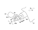
図2は、外ローラ80のアライメント調整機構の概略構成を示す斜視図である。   FIG. 2 is a perspective view showing a schematic configuration of the alignment adjustment mechanism of the outer roller 80.

アライメント調整機構は、図2に示すように、外ローラ80と、ステアリングモータ81と、軸受82と、長軸受83とから構成されている。   As shown in FIG. 2, the alignment adjustment mechanism includes an outer roller 80, a steering motor 81, a bearing 82, and a long bearing 83.

外ローラ80の前側の軸端部80aは、図示しない側板に固定された長軸受83に回転可能に軸支されている。長軸受83には、矢印R1,R2方向(図1において矢印C方向)に移動可能に且つ回転可能に軸端部80aを支持する長穴83aが形成されている。また、軸端部80aには、長軸受83より前側に、軸受82が嵌合されている。ステアリングモータ81は上記図示しない側板に固定されている。ステアリングモータ81の先端部には、リードが設けられた出力軸81aが取り付けられており、出力軸81aの先端部が軸受82に当接している。軸受82の反対側には、図示しないバネ部材が設けてあり、軸受82を矢印R1方向に付勢して出力軸81aに押し付けている。   A shaft end portion 80a on the front side of the outer roller 80 is rotatably supported by a long bearing 83 fixed to a side plate (not shown). The long bearing 83 is formed with a long hole 83a that supports the shaft end 80a so as to be movable and rotatable in the directions of arrows R1 and R2 (in the direction of arrow C in FIG. 1). In addition, a bearing 82 is fitted to the shaft end 80 a in front of the long bearing 83. The steering motor 81 is fixed to the side plate (not shown). An output shaft 81 a provided with a lead is attached to the distal end portion of the steering motor 81, and the distal end portion of the output shaft 81 a is in contact with the bearing 82. A spring member (not shown) is provided on the opposite side of the bearing 82, and the bearing 82 is urged in the direction of the arrow R1 and pressed against the output shaft 81a.

上記アライメント調整機構において、ステアリングモータ81を所定のステップ数だけ矢印M1方向に回転すると、出力軸81aが所定量だけ矢印L1方向に移動して、軸受82が所定量だけ矢印L1方向に移動する。一方、ステアリングモータ81が所定のステップ数だけ矢印M2方向に回転すると、出力軸81aが所定量だけ矢印L2方向に移動して、軸受82が所定量だけ矢印L2方向に移動する。このように、ステアリングモータ81を回転させることにより、外ローラ80の前側の軸端部80aを矢印R1あるいはR2方向へ動かすことができる。このため、外ローラ80のアライメントを調整することが可能となる。   In the alignment adjustment mechanism, when the steering motor 81 is rotated in the arrow M1 direction by a predetermined number of steps, the output shaft 81a is moved in the arrow L1 direction by a predetermined amount, and the bearing 82 is moved in the arrow L1 direction by a predetermined amount. On the other hand, when the steering motor 81 rotates in the arrow M2 direction by a predetermined number of steps, the output shaft 81a moves in the arrow L2 direction by a predetermined amount, and the bearing 82 moves in the arrow L2 direction by a predetermined amount. Thus, by rotating the steering motor 81, the shaft end 80a on the front side of the outer roller 80 can be moved in the direction of the arrow R1 or R2. For this reason, the alignment of the outer roller 80 can be adjusted.

上記アライメント調整機構によって外ローラ80のアライメントを調整することにより、中間転写ベルト31の寄り方向を制御することができる。外ローラ80の前側の軸端部80aを矢印R1の方向に動かすと、中間転写ベルト31には矢印S2の方向に寄り力が生じる。一方、外ローラ80の前側の軸端部80aを矢印R2の方向に動かすと、中間転写ベルト31には矢印S1の方向に寄り力が生じる。この特性を利用して外ローラ80のアライメントを調整することにより、装置本体の歪み等によって中間転写ベルト31に発生する寄り力を相殺する方向の寄り力を積極的に生じさせ、結果的に中間転写ベルト31が所定位置から外れることなく走行させることが可能となる。   By adjusting the alignment of the outer roller 80 by the alignment adjusting mechanism, the shifting direction of the intermediate transfer belt 31 can be controlled. When the shaft end 80a on the front side of the outer roller 80 is moved in the direction of the arrow R1, a biasing force is generated on the intermediate transfer belt 31 in the direction of the arrow S2. On the other hand, when the shaft end 80a on the front side of the outer roller 80 is moved in the direction of the arrow R2, a biasing force is generated in the intermediate transfer belt 31 in the direction of the arrow S1. By adjusting the alignment of the outer roller 80 using this characteristic, a shifting force in a direction that cancels the shifting force generated in the intermediate transfer belt 31 due to distortion of the apparatus main body or the like is positively generated, and as a result, an intermediate force is generated. The transfer belt 31 can run without being deviated from a predetermined position.

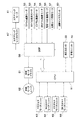
次いで、画像形成装置1の電気的構成について説明する。図3は、画像形成装置1の内部の電気的構成を示す回路ブロック図である。   Next, the electrical configuration of the image forming apparatus 1 will be described. FIG. 3 is a circuit block diagram showing an internal electrical configuration of the image forming apparatus 1.

図3に示すように、画像形成装置1は、DSP(デジタルシグナルプロセッサ)50と、CPU51と、給紙モータユニット62を制御する給紙モータドライバ61と、ステアリングモータ81を制御するステアリングモータドライバ67とを備える。   As shown in FIG. 3, the image forming apparatus 1 includes a DSP (digital signal processor) 50, a CPU 51, a paper feed motor driver 61 that controls the paper feed motor unit 62, and a steering motor driver 67 that controls the steering motor 81. With.

DSP50には、各色の感光ドラム11a,11b,11c,11dを夫々回転駆動するドラム駆動モータ52,53,54,55、転写ベルト駆動ローラ32を回転駆動する転写ベルト駆動モータ56、定着ローラ41aを回転駆動する定着ローラ駆動モータ57、画像センサユニット60、給紙モータドライバ61、及びステアリングモータドライバ67が接続されている。CPU51には、各感光ドラム11a,11b,11c,11dに光線を夫々走査する各色スキャナモータユニット63,64,65,66、定着ユニット40、及び一次転写装置35a,35b,35c,35d及び二次転写装置36に高電圧を印加する高圧ユニット59が接続されている。   The DSP 50 includes drum driving motors 52, 53, 54, and 55 for rotating the photosensitive drums 11a, 11b, 11c, and 11d of the respective colors, a transfer belt driving motor 56 for rotating the transfer belt driving roller 32, and a fixing roller 41a. A fixing roller driving motor 57 that rotationally drives, an image sensor unit 60, a paper feed motor driver 61, and a steering motor driver 67 are connected. The CPU 51 includes color scanner motor units 63, 64, 65, and 66 that scan the light beams on the photosensitive drums 11a, 11b, 11c, and 11d, a fixing unit 40, primary transfer devices 35a, 35b, 35c, and 35d, and secondary colors. A high voltage unit 59 for applying a high voltage is connected to the transfer device 36.

ドラム駆動モータ52〜56、転写ベルト駆動モータ56、定着ローラ駆動モータ57、画像センサユニット60、給紙モータドライバ61、及びステアリングモータドラバ67はDSP50によって制御され、スキャナモータユニット63〜66、高圧ユニット59、及び定着ユニット40はCPU51によって制御される。   The drum drive motors 52 to 56, the transfer belt drive motor 56, the fixing roller drive motor 57, the image sensor unit 60, the paper feed motor driver 61, and the steering motor driver 67 are controlled by the DSP 50, and the scanner motor units 63 to 66, the high voltage unit. 59 and the fixing unit 40 are controlled by the CPU 51.

次いで、図4を用いてDSP50によって制御される各ドラム駆動モータ52〜55及び転写ベルト駆動モータ56の概略構成について説明する。各ドラム駆動モータ52〜55及び転写ベルト駆動モータ56は図4に示す三相DCモータ404を内蔵するDCモータユニット401によって構成されている。   Next, the schematic configuration of each of the drum drive motors 52 to 55 and the transfer belt drive motor 56 controlled by the DSP 50 will be described with reference to FIG. Each of the drum driving motors 52 to 55 and the transfer belt driving motor 56 is constituted by a DC motor unit 401 incorporating a three-phase DC motor 404 shown in FIG.

図4に示すように、DCモータユニット401は、三相DCモータ404の他に、制御IC402、及びドライバ403を備えている。制御IC402は、プリドライバ405、及び論理回路406を有している。また、DCモータユニット401は、制御IC402に接続され、且つ三相DCモータ404に近接して配置された3つのホールセンサ407,408,409と、速度検知用MRセンサ410とを備えている。   As shown in FIG. 4, the DC motor unit 401 includes a control IC 402 and a driver 403 in addition to the three-phase DC motor 404. The control IC 402 includes a pre-driver 405 and a logic circuit 406. The DC motor unit 401 includes three Hall sensors 407, 408, and 409 connected to the control IC 402 and arranged close to the three-phase DC motor 404, and a speed detection MR sensor 410.

DSP50は、速度検知用MRセンサ410からの速度検知信号413によってモータ回転速度を演算し、三相DCモータ404が目標速度(回転数)となるようPWM信号412を制御する。制御IC402はホールセンサ407〜409の検知信号に応じて各コイルに流れる電流方向が所望の方向になるように各コイルに供給する電流の切り換えを行っている。制御IC402から出力される電流はPWM信号412に基づいてドライバ403において増幅され、増幅された電流が三相DCモータ404の各コイルへ供給される。尚、図4において、411はDCモータ404の起動コマンドとしてのモータ起動信号である。   The DSP 50 calculates the motor rotation speed based on the speed detection signal 413 from the speed detection MR sensor 410 and controls the PWM signal 412 so that the three-phase DC motor 404 becomes the target speed (rotation speed). The control IC 402 switches the current supplied to each coil so that the direction of the current flowing through each coil becomes a desired direction according to the detection signals of the hall sensors 407 to 409. The current output from the control IC 402 is amplified by the driver 403 based on the PWM signal 412, and the amplified current is supplied to each coil of the three-phase DC motor 404. In FIG. 4, reference numeral 411 denotes a motor start signal as a start command for the DC motor 404.

次いで、図5を用いて画像センサユニット60の構成について説明する。図5は、画像センサユニット60の概略構成を示す図である。   Next, the configuration of the image sensor unit 60 will be described with reference to FIG. FIG. 5 is a diagram illustrating a schematic configuration of the image sensor unit 60.

画像センサユニット60は、図1,5に示すように、中間転写ユニット10において中間転写ベルト31に対向するように配置されており、照明部材であるLED601、画像作成部材であるCMOSセンサ602、レンズ603、及び結像レンズ604を備えている。LED601を光源とする光はレンズ603を介して、中間転写ベルト31の表面あるいは転写材Pの表面に対し斜めに照射される。そして、中間転写ベルト31又は転写材Pに照射された光の反射光は結像レンズ604を介して集光されてCMOSセンサ602に結像される。このようにして、画像センサユニット60は、中間転写ベルト31の表面状態あるいは転写材Pの表面画像を読み取って、対応する画像データを作成することができる。また、本実施の形態においては、照明部材にLEDを用いているが照明部材はLED限られるものではなく、例えばレーザ等の光源であってもよい。   As shown in FIGS. 1 and 5, the image sensor unit 60 is disposed so as to face the intermediate transfer belt 31 in the intermediate transfer unit 10. The image sensor unit 60 is an LED 601 that is an illumination member, a CMOS sensor 602 that is an image creation member, a lens. 603 and the imaging lens 604 are provided. Light using the LED 601 as a light source is irradiated obliquely to the surface of the intermediate transfer belt 31 or the surface of the transfer material P via the lens 603. Then, the reflected light of the light irradiated on the intermediate transfer belt 31 or the transfer material P is condensed via the imaging lens 604 and imaged on the CMOS sensor 602. In this way, the image sensor unit 60 can read the surface state of the intermediate transfer belt 31 or the surface image of the transfer material P and create corresponding image data. Moreover, in this Embodiment, although LED is used for the illumination member, an illumination member is not restricted to LED, For example, light sources, such as a laser, may be sufficient.

次いで、画像センサユニット60の作成する表面画像について図6を参照して説明する。図6は画像センサユニット60が作成する中間転写ベルト31の表面画像の一例を示す図である。図6に示すように、画像センサユニット60によれば、中間転写ベルト31の表面状態を示す表面画像は、結像レンズ604によって拡大された拡大画像71として得ることができる。図6において、72は拡大画像71の一部をCMOSセンサ602によって階調検出したイメージを表した画像である。   Next, a surface image created by the image sensor unit 60 will be described with reference to FIG. FIG. 6 is a diagram illustrating an example of a surface image of the intermediate transfer belt 31 created by the image sensor unit 60. As shown in FIG. 6, according to the image sensor unit 60, a surface image indicating the surface state of the intermediate transfer belt 31 can be obtained as an enlarged image 71 enlarged by the imaging lens 604. In FIG. 6, reference numeral 72 denotes an image representing an image obtained by performing gradation detection on a part of the enlarged image 71 by the CMOS sensor 602.

中間転写ベルト31の表面は、キズや汚れ等によって凹凸が存在する。この凹凸には光を斜めから照射することによって影が発生するため、中間転写ベルト31の表面に光を斜めから照射することにより表面のパターンを容易に検出できる。   The surface of the intermediate transfer belt 31 is uneven due to scratches or dirt. Since shadows are generated on the irregularities by irradiating light obliquely, the surface pattern can be easily detected by irradiating the surface of the intermediate transfer belt 31 obliquely.

また、中間転写ベルト31の表面層において、画像形成のための転写制御に影響を与えない範囲に予め凹凸をつけることにより、CMOSセンサ602が読み取る中間転写ベルト31の表面パターンをより特徴づけることができる。   Further, the surface layer of the intermediate transfer belt 31 read by the CMOS sensor 602 can be further characterized by providing irregularities in advance in the surface layer of the intermediate transfer belt 31 so as not to affect the transfer control for image formation. it can.

さらに、中間転写ベルト31の表面層に透明な材質が用いられている場合は、中間層に凹凸あるいは任意のパターンを予め形成しておくことにより、転写に影響を与えず特徴づけられた表面パターンをCMOSセンサ602が検出することができる。   Further, when a transparent material is used for the surface layer of the intermediate transfer belt 31, a surface pattern characterized without affecting transfer by forming irregularities or arbitrary patterns in the intermediate layer in advance. Can be detected by the CMOS sensor 602.

図6の画像72は、1ピクセルが8ビット幅の分解能を有するの24×16ピクセルのCMOSセンサ602を用いて中間転写ベルト31の表面状態を読み込んだ場合に作成される表面画像の例を示している。尚、画像センサユニット60の画像作成部材としてはCMOSセンサ602の代わりにCCDセンサを用いることもできる。   An image 72 in FIG. 6 shows an example of a surface image created when the surface state of the intermediate transfer belt 31 is read using a 24 × 16 pixel CMOS sensor 602 in which one pixel has a resolution of 8 bits. ing. Note that a CCD sensor can be used instead of the CMOS sensor 602 as an image creating member of the image sensor unit 60.

次いで、図7を用いて画像センサユニット60の回路構成について説明する。図7は、画像センサユニット60の概略構成を示す回路図である。   Next, the circuit configuration of the image sensor unit 60 will be described with reference to FIG. FIG. 7 is a circuit diagram showing a schematic configuration of the image sensor unit 60.

図7に示すように、画像センサユニット回路60は、24×16ピクセルのCMOSセンサ602、コントロール回路611、A/Dコンバータ(A/D変換回路)612、フィルタ回路613、出力回路614、及びPLL回路615を含んでいる。   As shown in FIG. 7, the image sensor unit circuit 60 includes a 24 × 16 pixel CMOS sensor 602, a control circuit 611, an A / D converter (A / D conversion circuit) 612, a filter circuit 613, an output circuit 614, and a PLL. Circuit 615 is included.

図7の回路構成を有する画像センサユニット60の回路動作について図8を用いて説明する。図8は、画像センサユニット60の回路動作を説明するための図である。   The circuit operation of the image sensor unit 60 having the circuit configuration of FIG. 7 will be described with reference to FIG. FIG. 8 is a diagram for explaining the circuit operation of the image sensor unit 60.

DSP50は、/CS信号S1、CLOCK信号S2、及びDATA信号S3をシリアル通信によってコントロール回路(Control Logic)611に送信し、コントロール回路611におけるフィルタ回路613のフィルタ定数等の制御パラメータを設定する。   The DSP 50 transmits the / CS signal S1, the CLOCK signal S2, and the DATA signal S3 to the control circuit (Control Logic) 611 by serial communication, and sets control parameters such as a filter constant of the filter circuit 613 in the control circuit 611.

DSP50は、図8に示すように、Lowレベルの/CS信号S1を送信することにより、動作モードを制御パラメータ転送モードに切り替えて、DATA信号S3として8ビットのコマンド信号を送信する。コントロール回路611はこのコマンド信号に応じてフィルタ回路613を制御して、CMOSセンサ602の出力のゲインを決定する。   As shown in FIG. 8, the DSP 50 switches the operation mode to the control parameter transfer mode by transmitting a Low level / CS signal S1, and transmits an 8-bit command signal as the DATA signal S3. The control circuit 611 controls the filter circuit 613 according to this command signal, and determines the gain of the output of the CMOS sensor 602.

このCMOSセンサ602の出力のゲイン設定の目的は、例えば中間転写ベルト31の表面は材質によって反射率が異なるため、ゲインを調整して画像センサユニット60が常に最適な表面画像を作成できるようにするためである。   The purpose of setting the output gain of the CMOS sensor 602 is that, for example, the surface of the intermediate transfer belt 31 has a different reflectance depending on the material. Therefore, the gain is adjusted so that the image sensor unit 60 can always create an optimum surface image. Because.

DSP50は、CMOSセンサ602が読み込んだ中間転写ベルト31の表面状態に対するゲインを、後述する画像比較処理が精度よく実現できるようなレベルに調整するコマンド信号を出力する。例えば、読み込んだ表面状態を示す画像においてある程度のコントラストが形成されるまでCMOSセンサ602の出力のゲインを調整する。   The DSP 50 outputs a command signal for adjusting the gain with respect to the surface state of the intermediate transfer belt 31 read by the CMOS sensor 602 to a level at which an image comparison process described later can be realized with high accuracy. For example, the gain of the output of the CMOS sensor 602 is adjusted until a certain level of contrast is formed in the read image showing the surface state.

次いで、DSP50は、図8に示すように、Highレベルの/CS信号S1を出力して、動作モードをCMOSセンサ612から画像データを転送する画像データ転送モードに切り替える。出力回路(Output Logic)614はCLOCK信号S2をトリガにして、CMOSセンサ602の出力がA/Dコンバータ612及びフィルタ回路613を通過して変換されたディジタル画像情報をピクセル順にDSP50へ送信する。このとき、送信用同期クロックTXCS4が、CLOCK信号S2に基づいてPLL回路615によって生成される。上述の動作によって、画像センサユニット60が24×16ピクセルデータ(PIXEL0,1,…,8)を順次作成し、DSP50が24×16ピクセルデータ(PIXEL0、1、…)を順次受信する。   Next, as shown in FIG. 8, the DSP 50 outputs a high-level / CS signal S <b> 1 and switches the operation mode to an image data transfer mode in which image data is transferred from the CMOS sensor 612. The output circuit (Output Logic) 614 uses the CLOCK signal S2 as a trigger, and transmits the digital image information obtained by converting the output of the CMOS sensor 602 through the A / D converter 612 and the filter circuit 613 to the DSP 50 in pixel order. At this time, the transmission synchronization clock TXCS4 is generated by the PLL circuit 615 based on the CLOCK signal S2. Through the above-described operation, the image sensor unit 60 sequentially creates 24 × 16 pixel data (PIXEL0, 1,..., 8), and the DSP 50 sequentially receives 24 × 16 pixel data (PIXEL0, 1,...).

次いで、DSP50の概略構成について図9を参照して説明する。図9は、DSP50の概略構成を示すブロック図である。   Next, a schematic configuration of the DSP 50 will be described with reference to FIG. FIG. 9 is a block diagram showing a schematic configuration of the DSP 50.

図9に示すように、DSP50は、サンプリング制御部501と、画像バッファ502と、画像メモリ503と、画像比較処理部504と、速度演算処理部505と、モータ速度制御部506と、I/O制御部507と、照明制御部508とを備える。   As shown in FIG. 9, the DSP 50 includes a sampling control unit 501, an image buffer 502, an image memory 503, an image comparison processing unit 504, a speed calculation processing unit 505, a motor speed control unit 506, and an I / O. A control unit 507 and an illumination control unit 508 are provided.

DSP50において、サンプリング制御部501は、サンプリング手段として機能し、CMOSセンサ602から読み込んだ中間転写ベルト31の表面状態を示す表面画像を所定のサンプリング周期でサンプリングする。画像バッファ502及び画像メモリ503は記憶手段である。画像比較処理部504は、後述するモータ速度制御処理及び寄り制御処理において画像比較処理を行う。速度演算処理部505は、後述するように、モータ速度制御処理及び寄り制御処理において各種演算処理を行う。また、速度演算処理部505は、検出データからノイズ等を除去するためのフィルタ処理を実行するフィルタ処理部505aを備える。   In the DSP 50, the sampling control unit 501 functions as a sampling unit and samples a surface image indicating the surface state of the intermediate transfer belt 31 read from the CMOS sensor 602 at a predetermined sampling period. The image buffer 502 and the image memory 503 are storage means. The image comparison processing unit 504 performs image comparison processing in motor speed control processing and shift control processing described later. As will be described later, the speed calculation processing unit 505 performs various calculation processes in the motor speed control process and the shift control process. Further, the speed calculation processing unit 505 includes a filter processing unit 505a that executes a filter process for removing noise and the like from the detection data.

モータ速度制御部506は、後述するようにモータ速度制御処理において、中間転写ベルト31の走行速度が所定の目標走行速度となるように転写ベルト駆動モータ56を制御する。また、モータ速度制御部506は、後述するように寄り制御処理において、中間転写ベルト31の寄り量が所定の範囲内となるようにアライメント調整機構のステアリングモータ81を駆動制御する。   The motor speed control unit 506 controls the transfer belt drive motor 56 so that the traveling speed of the intermediate transfer belt 31 becomes a predetermined target traveling speed in the motor speed control process as described later. Further, the motor speed control unit 506 drives and controls the steering motor 81 of the alignment adjustment mechanism so that the shift amount of the intermediate transfer belt 31 is within a predetermined range in the shift control process as described later.

I/O制御部507は、画像センサユニット60との間で図8に示す信号等のデータの送受信を行うための入出力部である。照明制御部(ロジック)508は、画像センサユニット60のLED601の照明光量を制御する照明光量制御手段である。   The I / O control unit 507 is an input / output unit for transmitting and receiving data such as signals shown in FIG. 8 to and from the image sensor unit 60. The illumination control unit (logic) 508 is illumination light quantity control means for controlling the illumination light quantity of the LED 601 of the image sensor unit 60.

DSP50において、サンプリング制御部501、画像メモリ503、速度演算処理部505、フィルタ演算部505aを、モータ速度制御部506、及び照明制御部508は、プログラマブルに制御可能に構成されている。   In the DSP 50, a sampling control unit 501, an image memory 503, a speed calculation processing unit 505, a filter calculation unit 505a, a motor speed control unit 506, and an illumination control unit 508 are configured to be programmable.

以下、DSP50の動作について説明する。   Hereinafter, the operation of the DSP 50 will be described.

DSP50は、後述するモータ速度制御処理及び寄り制御処理を行う。モータ速度制御処理においては、所定のサンプリング周期毎にサンプリングした中間転写ベルト31の表面画像に対して画像比較処理を行って相対移動量を演算し、この演算結果に基づいて中間転写ベルト31の走行速度が一定の目標走行速度となるように転写ベルト駆動モータ56の回転速度を制御する。また、寄り制御処理においては、演算した相対移動量に基づいて中間転写ベルト31の寄り量が所定の範囲内となるように図2のアライメント調整機構のステアリングモータ81を起動制御して外ローラ80のアライメントを調整する。尚、相対移動量とは、サンプリング周期間の移動量をいう。また、目標走行速度とは、画像形成装置1において予め設定されている中間転写ベルト31の走行速度であり、例えば、中間転写ベルト31のイニシャル走行速度である。上記寄り量の所定の範囲は、画像形成に問題が生じない範囲の中間転写ベルト31の寄り量であり、例えば予め実験により設定されている。   The DSP 50 performs a motor speed control process and a shift control process, which will be described later. In the motor speed control process, an image comparison process is performed on the surface image of the intermediate transfer belt 31 sampled at a predetermined sampling period to calculate a relative movement amount, and the intermediate transfer belt 31 travels based on the calculation result. The rotational speed of the transfer belt drive motor 56 is controlled so that the speed becomes a constant target traveling speed. Further, in the shift control process, the outer roller 80 is controlled by starting the steering motor 81 of the alignment adjustment mechanism in FIG. 2 so that the shift amount of the intermediate transfer belt 31 falls within a predetermined range based on the calculated relative movement amount. Adjust the alignment. The relative movement amount refers to the movement amount during the sampling period. The target travel speed is a travel speed of the intermediate transfer belt 31 set in advance in the image forming apparatus 1, for example, an initial travel speed of the intermediate transfer belt 31. The predetermined range of the shift amount is a shift amount of the intermediate transfer belt 31 in a range that does not cause a problem in image formation, and is set in advance by experiments, for example.

まず、中間転写ベルト31の相対移動量の演算方法について図10〜13を用いて説明する。   First, a method for calculating the relative movement amount of the intermediate transfer belt 31 will be described with reference to FIGS.

本実施の形態においては、図10に示すように、CMOSセンサ602によって中間転写ベルト31の表面状態を読み込んで24×16ピクセルの表面画像72を検出する。そして、図10に示すように、検出された表面画像72から所定の領域、例えば8×8ピクセル領域の表面画像73を上記サンプリング周期毎にサンプリング制御部501によってサンプリングする。次いで、サンプリングした表面画像73を中間転写ベルト31の転写材Pの搬送方向であるx方向、及びこの搬送方向に直交する方向(以下、寄り方向ともいう)であるy方向に1ピクセルずつずらしたズラシ表面画像を作成する。そして、次の周期でサンプリング制御部501によってサンプリングされたCMOSセンサ602からの表面画像(表面画像73参照)と上記作成したズラシ表面画像とを比較する画像比較処理を実行して相対移動量を演算する。具体的には、以下に示すように中間転写ベルト31の相対移動量の演算を行う。   In the present embodiment, as shown in FIG. 10, the surface state of the intermediate transfer belt 31 is read by the CMOS sensor 602 and a surface image 72 of 24 × 16 pixels is detected. Then, as shown in FIG. 10, a sampling region is sampled by the sampling control unit 501 for each sampling period from a detected surface image 72 in a predetermined region, for example, a surface image 73 of an 8 × 8 pixel region. Next, the sampled surface image 73 is shifted by one pixel in the x direction, which is the conveyance direction of the transfer material P, of the intermediate transfer belt 31 and in the y direction, which is a direction orthogonal to the conveyance direction (hereinafter also referred to as a shift direction). Create a slip surface image. Then, the relative movement amount is calculated by executing image comparison processing for comparing the surface image (see the surface image 73) from the CMOS sensor 602 sampled by the sampling control unit 501 in the next cycle with the generated displacement surface image. To do. Specifically, the relative movement amount of the intermediate transfer belt 31 is calculated as described below.

図11(A)に示すように、CMOSセンサ602によって中間転写ベルト31の表面状態を読み込み、読み込んだ表面状態を示す24×16ピクセルの表面画像(例えば、表面画像72)を作成する。そして、図10で説明したように、作成された表面画像72から8×8ピクセル領域の表面画像(表面画像73)をサンプリング制御部501が所定のサンプリング周期でサンプリングして画像バッファ502に取り込むと共に、リファレンス画像として画像メモリ503へ格納する。このとき、サンプリング制御部501は、図10で上述したように、検出表面画像72において上記サンプリングしたリファレンス画像(表面画像73)を中間転写ベルト31の搬送方向であるx方向に1ピクセルずつずらしたズラシ表面画像(表面画像101〜108)を作成して画像メモリ504に格納する(図11(B)〜(I)参照)。つまり、ズラシ表面画像101〜108は、リファレンス画像73に対応する中間転写ベルト31の表面上の位置から中間転写ベルト31の搬送方向に1ピクセルずつずらした位置の表面状態を示す画像となる。例えば、ズラシ表面画像101は、搬送方向に1ピクセルずらした位置の表面状態を示す画像であり、ズラシ表面画像108は、搬送方向に8ピクセルずらした位置の表面状態を示す画像である。   As shown in FIG. 11A, the surface state of the intermediate transfer belt 31 is read by the CMOS sensor 602, and a 24 × 16 pixel surface image (for example, the surface image 72) indicating the read surface state is created. Then, as described with reference to FIG. 10, the sampling control unit 501 samples the surface image (surface image 73) of the 8 × 8 pixel region from the created surface image 72 at a predetermined sampling period and imports it into the image buffer 502. Then, it is stored in the image memory 503 as a reference image. At this time, as described above with reference to FIG. 10, the sampling control unit 501 shifts the sampled reference image (surface image 73) in the detected surface image 72 pixel by pixel in the x direction that is the conveyance direction of the intermediate transfer belt 31. Gap surface images (surface images 101 to 108) are created and stored in the image memory 504 (see FIGS. 11B to 11). That is, the slip surface images 101 to 108 are images indicating the surface state at positions shifted by one pixel from the position on the surface of the intermediate transfer belt 31 corresponding to the reference image 73 in the conveyance direction of the intermediate transfer belt 31. For example, the displacement surface image 101 is an image showing the surface state at a position shifted by 1 pixel in the conveyance direction, and the displacement surface image 108 is an image showing the surface state at a position shifted by 8 pixels in the conveyance direction.

また、サンプリグ制御部501は、図12(A)〜(I),13(A)〜(I)に示すように、リファレンス画像73をx方向と搬送方向(x方向)に直交するy方向の両方向に夫々1ピクセルずつずらしたズラシ表面画像111〜118,121〜128を作成して画像メモリ504に格納する。つまり、ズラシ表面画像111〜118は、リファレンス画像73に対応する中間転写ベルト31の表面上の位置からx方向及び+y方向(手前側)に夫々1ピクセルずつずらした位置の表面状態を示す画像となる。また、ズラシ表面画像121〜128は、リファレンス画像73に対応する中間転写ベルト31の表面上の位置からx方向及び−y方向(奥側)に夫々1ピクセルずつずらした位置の表面状態を示す画像となる。例えば、ズラシ表面画像111は、搬送方向に1ピクセル、寄り方向手前側に1ピクセルずらした位置の表面状態を示す画像であり、ズラシ表面画像118は、搬送方向に8ピクセル、寄り方向手前側に8ピクセルずらした位置の表面状態を示す画像である。また、ズラシ表面画像121は、搬送方向に1ピクセル、寄り方向奥側に1ピクセルずらした位置の表面状態を示す画像であり、ズラシ表面画像128は、搬送方向に8ピクセル、寄り方向奥側に8ピクセルずらした位置の表面状態を示す画像である。   Also, the sampling controller 501 converts the reference image 73 in the y direction orthogonal to the x direction and the transport direction (x direction), as shown in FIGS. 12 (A) to (I) and 13 (A) to (I). Gap surface images 111 to 118 and 121 to 128 shifted by one pixel in both directions are created and stored in the image memory 504. That is, the slip surface images 111 to 118 are images indicating the surface state at positions shifted by one pixel in the x direction and the + y direction (front side) from the position on the surface of the intermediate transfer belt 31 corresponding to the reference image 73. Become. Further, the slip surface images 121 to 128 are images showing surface states at positions shifted by one pixel in the x direction and the −y direction (back side) from the position on the surface of the intermediate transfer belt 31 corresponding to the reference image 73. It becomes. For example, the slip surface image 111 is an image showing a surface state at a position shifted by 1 pixel in the transport direction and 1 pixel in the front side of the shift direction, and the shift surface image 118 is 8 pixels in the transport direction and on the front side of the shift direction. It is an image which shows the surface state of the position shifted 8 pixels. The displacement surface image 121 is an image showing the surface state at a position shifted by 1 pixel in the transport direction and 1 pixel in the back direction, and the slip surface image 128 is 8 pixels in the transport direction and on the back side in the shift direction. It is an image which shows the surface state of the position shifted 8 pixels.

上述のズラシ表面画像の作成は、中間転写ベルト31の搬送方向と寄りの方向の2方向に対して1ピクセルずつずらした画像を作成することで、搬送方向と寄り方向の2方向の相対移動量を検知することを可能にするためである。尚、中間転写ベルト31は、画像形成装置1の手前側に寄る場合と奥側に寄る場合があるため、手前側方向の+y方向と奥側方向の−y方向の各方向に対するズラシ表面画像を作成する。即ち、図12(B)〜(I)に示すように、x方向と+y方向に夫々1ピクセルずつずらしたズラシ表面画像111〜118と、図13(B)〜(I)に示すように、x方向と−y方向に夫々1ピクセルずつずらしたズラシ表面画像121〜128とを作成する。   The above-described slip surface image is created by creating an image that is shifted by one pixel with respect to the two directions of the intermediate transfer belt 31 in the transport direction and the shift direction, and thereby the relative movement amount in the two directions of the transport direction and the shift direction. This is to make it possible to detect this. Since the intermediate transfer belt 31 may approach the front side or the back side of the image forming apparatus 1, the intermediate transfer belt 31 may display a slip surface image in each of the + y direction in the front direction and the −y direction in the back direction. create. That is, as shown in FIGS. 12B to 12I, the shift surface images 111 to 118 shifted by one pixel in the x direction and the + y direction, respectively, and as shown in FIGS. 13B to 13I, Gap surface images 121 to 128 are created by shifting one pixel each in the x and −y directions.

そして、画像比較処理部504において画像比較処理を実行する。具体的には、サンプリング制御部501によって新たにサンプリングされたCMOSセンサ602からの表面画像と、画像メモリ503に格納されたリファレンス画像(表面画像73)及びズラシ表面画像(表面画像101〜108,111〜118,121〜128)を比較して、新たにサンプリングされた表面画像に一致する画像を検索する。画像比較処理においては、完全に一致しなくても一致する割合が所定のパーセンテージ以上であったときに、一致すると判断してもよい。そして、一致した画像がリファレンス画像73から何ピクセルずらした画像であるかを導く。このため、作成したズラシ表面画像は、リファレンス画像からx方向及びy方向に何ピクセルずらしたかを示す情報(以下、ピクセルずらし数という)と共に画像メモリ503に格納する。   Then, the image comparison processing unit 504 executes image comparison processing. Specifically, the surface image from the CMOS sensor 602 newly sampled by the sampling controller 501, the reference image (surface image 73) and the surface image (surface images 101 to 108, 111) stored in the image memory 503. ˜118, 121-128) to find an image that matches the newly sampled surface image. In the image comparison process, it may be determined that there is a match when the matching ratio is not less than a predetermined percentage even if it does not match completely. Then, the number of pixels shifted from the reference image 73 by the matched image is derived. Therefore, the created displacement surface image is stored in the image memory 503 together with information indicating how many pixels are shifted in the x and y directions from the reference image (hereinafter referred to as the pixel shift number).

次いで、速度演算処理部506において画像比較処理結果に基づく演算処理を行う。演算処理においては、例えば、サンプリング画像が、リファレンス画像に対してx方向に5ピクセル移動した画像(図11(F)参照)と一致する場合は、1ピクセルの大きさが10μmならば、中間転写ベルト31が50μm移動したことが算出される。また、サンプリング周期が1kHzであるとすると、前回のサンプリング時の中間転写ベルト31の走行速度に対して0.05mm×1kHz=50mm/secの相対速度が求められる。   Next, the speed calculation processing unit 506 performs calculation processing based on the image comparison processing result. In the arithmetic processing, for example, when the sampling image matches an image (see FIG. 11F) moved by 5 pixels in the x direction with respect to the reference image, if the size of one pixel is 10 μm, intermediate transfer is performed. It is calculated that the belt 31 has moved by 50 μm. If the sampling period is 1 kHz, a relative speed of 0.05 mm × 1 kHz = 50 mm / sec is obtained with respect to the traveling speed of the intermediate transfer belt 31 at the previous sampling.

また、y方向に対しても同様に、サンプリング画像がリファレンス画像に対して搬送方向と直交方向である+y方向に5ピクセル移動した画像(図12(F)参照)と一致する場合は、1ピクセルの大きさが10μmならば、中間転写ベルト31は手前側に50μm移動したことが算出される。また、サンプリング画像が−y方向に5ピクセル移動した画像と一致する場合は、中間転写ベルト31は奥側に50μm移動したことが算出される。この移動量から寄り量の算出が可能となる。   Similarly, in the y direction, if the sampling image coincides with an image (see FIG. 12F) moved by 5 pixels in the + y direction, which is orthogonal to the transport direction, with respect to the reference image, 1 pixel. Is 10 μm, it is calculated that the intermediate transfer belt 31 has moved 50 μm to the near side. If the sampled image matches the image moved by 5 pixels in the −y direction, it is calculated that the intermediate transfer belt 31 has moved 50 μm to the back side. The shift amount can be calculated from the movement amount.

つまり、本実施の形態においては、DSP50において、CMOSセンサ602から読み込んだ中間転写ベルト31の表面画像をサンプリング制御部501が一定のサンプリング周期でサンプリングする。次いで、サンプリングした表面画像を内部バッファ502へ取り込むと共に、リファレンス画像として画像メモリ503へ格納する。そして、サンプリングした表面画像と、予め1つ前のサンプリング周期でサンプリングしたリファレンス画像及びこのリファレンス画像に基づいて作成したズラシ表面画像とを画像メモリ503から読み出し、画像比較処理部504において画像比較処理によって順次比較演算する。次いで、速度演算処理部505において、画像比較処理の結果から、中間転写ベルト31の搬送方向及び寄り方向の画像ずれ量を検出し、1つ前のサンプリング画像が、次にサンプリングしたときに搬送方向及び寄り方向に対して何画素分シフトしたかを導いて相対移動量を算出する。そして、この結果及びサンプリング周期から中間転写ベルト31の相対速度を算出すると共に、寄り方向に対しての寄り量の算出を行う。   That is, in the present embodiment, in the DSP 50, the sampling control unit 501 samples the surface image of the intermediate transfer belt 31 read from the CMOS sensor 602 at a constant sampling cycle. Next, the sampled surface image is taken into the internal buffer 502 and stored as a reference image in the image memory 503. Then, the sampled surface image, the reference image sampled in advance in the previous sampling period, and the displacement surface image created based on this reference image are read from the image memory 503, and the image comparison processing unit 504 performs image comparison processing. Sequential comparison operation. Next, the speed calculation processing unit 505 detects the image shift amount in the transport direction and the shift direction of the intermediate transfer belt 31 from the result of the image comparison process, and the transport direction when the previous sampled image is sampled next time. The relative movement amount is calculated by deriving how many pixels are shifted with respect to the shift direction. Then, the relative speed of the intermediate transfer belt 31 is calculated from the result and the sampling period, and the shift amount with respect to the shift direction is calculated.

そして、上記算出結果から、後述するように、モータ速度制御処理においては、モータ速度制御部506においてモータの制御速度を求め、サーボ制御を行う。さらに、寄り制御処理においては、中間転写ベルト31の寄り量に対応したステップ数の駆動パルスをモータ速度制御部506から送出してステアリングモータ81を回転させることにより、中間転写ベルト31の寄り方向の位置を所定の範囲内に制御する。   From the above calculation results, as will be described later, in the motor speed control process, the motor speed control unit 506 calculates the motor control speed and performs servo control. Further, in the shift control process, a drive pulse having the number of steps corresponding to the shift amount of the intermediate transfer belt 31 is sent from the motor speed control unit 506 and the steering motor 81 is rotated, thereby moving the intermediate transfer belt 31 in the shift direction. The position is controlled within a predetermined range.

なお、前記演算処理によって導いた中間転写ベルト31の相対速度及び寄り量は、検出ノイズや演算誤差を含むため、フィルタ処理部505aによってフィルタ処理を施し、モータのサーボ制御に適した制御速度及びステッピングモータ制御に適した駆動パルスの導出を可能にしている。例えば、検出ノイズによって中間転写ベルト31の相対速度が急激に変化する値となると、サーボモータの制御速度が急激に変化して、かえって画像を劣化させてしまう。さらに寄り制御においては、寄り量が急激に変化する値となると、ステッピングモータの駆動パルス数が急激に変化して、モータが脱調する可能性がある。   Since the relative speed and shift amount of the intermediate transfer belt 31 derived by the calculation process include detection noise and calculation error, the filter process is performed by the filter processing unit 505a, and the control speed and stepping suitable for the servo control of the motor are performed. This makes it possible to derive drive pulses suitable for motor control. For example, if the relative speed of the intermediate transfer belt 31 changes suddenly due to detection noise, the control speed of the servo motor changes suddenly, degrading the image. Further, in the shift control, when the shift amount becomes a value that changes abruptly, the number of drive pulses of the stepping motor may change abruptly and the motor may step out.

これを防ぐために、フィルタ処理部505aにおいて前記検出した相対速度に対してフィルタ処理を施した後に、モータ速度制御部506においてサーボモータの制御速度を算出している。また、寄り制御に関しても同様にフィルタ処理部505aにおいてフィルタ処理を施した後に、モータ速度制御部506において寄り量に応じたステップ数の駆動パルス信号を送出することにより最適なステッピングモータ制御を可能にしている。   In order to prevent this, the motor speed control unit 506 calculates the control speed of the servo motor after the filter processing unit 505a performs the filter process on the detected relative speed. Similarly, with respect to the shift control, after the filter processing unit 505a performs the filter process, the motor speed control unit 506 transmits the drive pulse signal having the number of steps corresponding to the shift amount, thereby enabling optimal stepping motor control. ing.

次いで、図14を用いてDSP50による中間転写ベルト31のモータ速度制御処理について説明する。図14は、DSP50が実行するモータ速度制御処理のフローチャートである。本モータ速度制御処理においては速度検出処理、及びモータサーボ制御処理が実行される。   Next, the motor speed control process of the intermediate transfer belt 31 by the DSP 50 will be described with reference to FIG. FIG. 14 is a flowchart of a motor speed control process executed by the DSP 50. In this motor speed control process, a speed detection process and a motor servo control process are executed.

モータ速度制御処理を開始すると、まず、DSP50がLED601を点灯させて中間転写ベルト31の表面にLED光を照射させる(ステップS131)。次いで、図15で後述する速度検出処理を行う(ステップS132)。速度制御処理を実行後、LED601を消灯させ(ステップS133)、転写ベルト駆動モータ56の目標速度を設定する(ステップS134)。ステップS134においては、速度検出制御処理において算出した中間転写ベルト31の平均相対速度に応じて中間転写ベルト31の走行速度が目標走行速度となり一定の速度となるように転写ベルト駆動モータ56の目標速度を設定する。ステップS134における転写ベルト駆動モータ56の目標速度の設定は速度演算処理部505で行う。そして、図16で後述する転写ベルト駆動モータ56のサーボ制御処理を実行して(ステップS135)、本処理を終了する。   When the motor speed control process is started, first, the DSP 50 turns on the LED 601 to irradiate the surface of the intermediate transfer belt 31 with LED light (step S131). Next, speed detection processing described later with reference to FIG. 15 is performed (step S132). After executing the speed control process, the LED 601 is turned off (step S133), and the target speed of the transfer belt drive motor 56 is set (step S134). In step S134, the target speed of the transfer belt drive motor 56 is set so that the traveling speed of the intermediate transfer belt 31 becomes the target traveling speed and becomes a constant speed according to the average relative speed of the intermediate transfer belt 31 calculated in the speed detection control process. Set. The setting of the target speed of the transfer belt drive motor 56 in step S134 is performed by the speed calculation processing unit 505. Then, a servo control process for the transfer belt drive motor 56, which will be described later with reference to FIG. 16, is executed (step S135), and this process ends.

次いで、図14のモータ速度制御処理のステップS132において実行する転写ベルト駆動モータ56の速度を検出する速度検出処理について説明する。図15は、モータ速度制御処理のステップS132において実行される速度検出処理のフローチャートである。   Next, the speed detection process for detecting the speed of the transfer belt drive motor 56 executed in step S132 of the motor speed control process of FIG. 14 will be described. FIG. 15 is a flowchart of the speed detection process executed in step S132 of the motor speed control process.

まず、クロック信号S2に基づいてサンプリング周期(例えば、1ms)を決定するための割り込み信号を監視し(ステップS141)、割り込み信号を受信しない場合は本処理を終了する。一方、割り込み信号を受信した場合は、割り込み信号の受信時にCMOSセンサ602によって中間転写ベルト31の表面状態を読み込んで表面画像(例えば図10の画像72)を作成する(ステップS142)。次いで、ステップS142において作成した表面画像(画像データ)をA/Dコンバータ612によってA/D変換し、CMOSセンサ602が検出した表面状態から最適な表面画像を作成することができるようにフィルタ回路613のゲインを調整する(ステップS143)。次いで、フィルタ回路613において、A/D変換された表面画像に対してフィルタ処理を行う(ステップS144)。このフィルタ処理によって、例えば、CMOSセンサ602の検出した8ビット256階調データを16階調データへ落とし、検出データからノイズ等による成分を除去する。そして、サンプリング制御部501によって、フィルタ処理された表面画像をサンプリングする。   First, an interrupt signal for determining a sampling period (for example, 1 ms) is monitored based on the clock signal S2 (step S141). If no interrupt signal is received, this process is terminated. On the other hand, when an interrupt signal is received, the surface state of the intermediate transfer belt 31 is read by the CMOS sensor 602 when the interrupt signal is received to create a surface image (for example, the image 72 in FIG. 10) (step S142). Next, the surface image (image data) created in step S142 is A / D converted by the A / D converter 612, and the filter circuit 613 can create an optimum surface image from the surface state detected by the CMOS sensor 602. Is adjusted (step S143). Next, the filter circuit 613 performs filter processing on the A / D converted surface image (step S144). By this filtering process, for example, 8-bit 256 gradation data detected by the CMOS sensor 602 is reduced to 16 gradation data, and a component due to noise or the like is removed from the detection data. Then, the filtered surface image is sampled by the sampling control unit 501.

次いで、サンプリング制御部501によってサンプリングされたサンプリング画像(図10の画像73参照)を前回の処理において予め画像メモリ503に記憶されている比較画像と比較する画像比較処理を実行し、サンプリング画像に一致する比較画像があるか否かを判別する(ステップS145)。この比較画像は、上述のリファレンス画像73と、ズラシ表面画像101〜108,111〜118,121〜128に相当する(図11(A)〜(I)、図12(A)〜(I)、図13(A)〜(I)参照)。サンプリング画像に一致する比較画像がない場合は、ステップS150の処理に移行する。一方、サンプリング画像に一致する比較画像がある場合は、一致する比較画像のx方向のピクセルずらし数を画像メモリ503から検出する(ステップS146)。そして、演算処理を実行し、上記所定のサンプリング周期とステップS146において検出したピクセルずらし数に基づいて中間転写ベルト31の相対速度を算出する(ステップS147)。   Next, an image comparison process is performed in which the sampled image sampled by the sampling control unit 501 (see the image 73 in FIG. 10) is compared with a comparative image stored in the image memory 503 in the previous process, and matches the sampled image. It is determined whether or not there is a comparison image to be performed (step S145). This comparison image corresponds to the reference image 73 described above and the slip surface images 101 to 108, 111 to 118, and 121 to 128 (FIGS. 11A to 11) and FIGS. 12A to 12I. (See FIGS. 13A to 13I). If there is no comparison image that matches the sampled image, the process proceeds to step S150. On the other hand, if there is a comparison image that matches the sampling image, the number of pixel shifts in the x direction of the matching comparison image is detected from the image memory 503 (step S146). Then, arithmetic processing is executed, and the relative speed of the intermediate transfer belt 31 is calculated based on the predetermined sampling period and the number of pixel shifts detected in step S146 (step S147).

次いで、予め設定された所定の期間にステップS147において算出された中間転写ベルト31の相対速度の算出結果の平均処理を行って、中間転写ベルト31の平均相対速度を算出し(ステップS148)、算出した平均相対速度を画像メモリ153に記憶する(ステップS149)。   Next, an average process of the calculation result of the relative speed of the intermediate transfer belt 31 calculated in step S147 is performed during a predetermined period set in advance to calculate the average relative speed of the intermediate transfer belt 31 (step S148). The average relative speed is stored in the image memory 153 (step S149).

次いで、今回の速度検出処理において作成されたサンプリング画像から、次回の速度検出処理のステップS145において使用する比較画像を作成し(ステップS150)、作成した比較画像を画像メモリ153に記憶して(ステップS151)、一連の速度検出処理を終了する。   Next, a comparison image used in step S145 of the next speed detection process is created from the sampling image created in the current speed detection process (step S150), and the created comparison image is stored in the image memory 153 (step S150). S151), a series of speed detection processing ends.

次いで、図14のモータ速度制御処理のステップS135において実行されるモータサーボ制御処理について説明する。図15は、図14のモータ速度制御処理のステップS135において実行されるモータサーボ制御処理のフローチャートである。本処理は、図15の速度検出処理において算出された中間転写ベルト31の平均相対速度に基づいて転写ベルト駆動モータ56の速度を一定の目標速度にサーボ制御する処理である。   Next, the motor servo control process executed in step S135 of the motor speed control process of FIG. 14 will be described. FIG. 15 is a flowchart of the motor servo control process executed in step S135 of the motor speed control process of FIG. This process is a process of servo-controlling the speed of the transfer belt drive motor 56 to a constant target speed based on the average relative speed of the intermediate transfer belt 31 calculated in the speed detection process of FIG.

本処理は、DSP50が転写ベルト駆動モータ56に対して起動コマンド411(図3参照)を送出した後に実行される。まず、転写ベルト駆動モータ56が目標速度に達していない状態であることを示すNOT−READY状態を示すフラグをセットし(ステップS161)、速度パルスを監視する(ステップS162)。ステップS162における速度パルスの監視は、図4に示した速度信号413のエッジ検出することによって行われる。   This process is executed after the DSP 50 sends a start command 411 (see FIG. 3) to the transfer belt drive motor 56. First, a flag indicating the NOT-READY state indicating that the transfer belt drive motor 56 has not reached the target speed is set (step S161), and the speed pulse is monitored (step S162). The speed pulse is monitored in step S162 by detecting the edge of the speed signal 413 shown in FIG.

次いで、転写ベルト駆動モータ56の回転速度を演算する(ステップS163)。この演算は速度演算処理部505において実行され、例えば、モータ1回転に30パルスの速度信号613が出力され、速度信号613のパルス幅がtsecの場合、転写ベルト駆動モータ56の回転速度ωは、ω=2π/30/t(rad/sec)となる。   Next, the rotational speed of the transfer belt drive motor 56 is calculated (step S163). This calculation is executed in the speed calculation processing unit 505. For example, when a speed signal 613 of 30 pulses is output for one rotation of the motor, and the pulse width of the speed signal 613 is tsec, the rotation speed ω of the transfer belt drive motor 56 is ω = 2π / 30 / t (rad / sec).

次いで、ステップS163において算出した転写ベルト駆動モータ56の回転速度ωが図14のモータ速度制御処理のステップS134において設定した目標速度の50%以上であるか否かを判別する(ステップS164)。   Next, it is determined whether or not the rotation speed ω of the transfer belt drive motor 56 calculated in step S163 is 50% or more of the target speed set in step S134 of the motor speed control process of FIG. 14 (step S164).

回転速度ωが目標速度の50%未満である場合は、PWMのオンデユーティを80%にセットして(ステップS165)、設定したオンデューティのPWMパルスを転写ベルト駆動モータ56に出力し(ステップS171)、本処理を終了する。   If the rotational speed ω is less than 50% of the target speed, the PWM on-duty is set to 80% (step S165), and the set on-duty PWM pulse is output to the transfer belt drive motor 56 (step S171). ), This process is terminated.

一方、回転速度ωが目標速度の50%以上である場合は、さらに回転速度ωが目標速度の±5%以内であるか否かを判別する(ステップS166)。回転速度ωが目標速度の±5%以内である場合は、転写ベルト駆動モータ56が目標回転数に到達したことを示すREADYフラグを設定し(ステップS167)、ステップS168の処理に移行する。一方、回転速度ωが目標速度の±5%以内でない場合は、直接ステップS168の処理に移行する。   On the other hand, if the rotational speed ω is 50% or more of the target speed, it is further determined whether or not the rotational speed ω is within ± 5% of the target speed (step S166). If the rotational speed ω is within ± 5% of the target speed, a READY flag indicating that the transfer belt drive motor 56 has reached the target rotational speed is set (step S167), and the process proceeds to step S168. On the other hand, if the rotational speed ω is not within ± 5% of the target speed, the process directly proceeds to step S168.

ステップS168においては、転写ベルト駆動モータ56の目標速度と実際の回転速度ωとの差を算出する。次いで、算出した目標速度差に対してPI演算(制御)を実行し(ステップS169)、その結果から目標速度差が0とするPWMパルス幅を求めて(S170)、算出したパルス幅のPWMパルスを転写ベルト駆動モータ56に出力し(S171)、本処理を終了する。   In step S168, the difference between the target speed of the transfer belt drive motor 56 and the actual rotational speed ω is calculated. Next, PI calculation (control) is performed on the calculated target speed difference (step S169), and a PWM pulse width for which the target speed difference is 0 is obtained from the result (S170), and a PWM pulse with the calculated pulse width is obtained. Is output to the transfer belt drive motor 56 (S171), and this process ends.

上述の一連のモータ速度制御処理によって、図4に示したDCモータユニット601において、出力されたPWMパルスに応じて転写ベルト駆動モータ56(三相DCモータ604)に供給される電力が制御される。これにより、転写ベルト駆動モータ56はその回転速度が目標速度に追従するようにサーボ制御が行われる。   In the DC motor unit 601 shown in FIG. 4, the electric power supplied to the transfer belt drive motor 56 (three-phase DC motor 604) is controlled in accordance with the output PWM pulse by the series of motor speed control processes described above. . Thus, the transfer belt drive motor 56 is servo-controlled so that its rotational speed follows the target speed.

次いで、図17を用いてDSP50において実行される中間転写ベルト31の寄り制御処理について説明する。図17は、DSP50において実行される中間転写ベルト31の寄り制御処理のフローチャートである。   Next, the shift control process of the intermediate transfer belt 31 executed in the DSP 50 will be described with reference to FIG. FIG. 17 is a flowchart of the deviation control process of the intermediate transfer belt 31 executed in the DSP 50.

寄り制御処理を開始すると、まず、DSP50がLED601を点灯させて中間転写ベルト31の表面にLED光を照射させ(ステップS181)、次いで、図19で後述する寄り量検出処理を実行する(ステップS182)。   When the shift control process is started, the DSP 50 first turns on the LED 601 to irradiate the surface of the intermediate transfer belt 31 with LED light (step S181), and then executes the shift amount detection process described later with reference to FIG. 19 (step S182). ).

寄り量検出処理が終了すると、次いで、LED601を消灯させ(ステップS183)、ステアリングモータ81の駆動パルス数を設定する(ステップS184)。具体的には、ステップS184の寄り量検出処理において算出した中間転写ベルト31の寄り量が上記所定の範囲内となるようにステアリングモータ81の駆動パルス数を設定する。そして、ステップS184において設定した駆動パルスをステアリングモータドライバ67に出力してステアリングモータ81の駆動制御を行う(ステップS185)。これにより、アライメント調整機構によって中間転写ベルト31の寄り量が上記所定の範囲内になる。   When the shift amount detection process ends, the LED 601 is then turned off (step S183), and the number of drive pulses of the steering motor 81 is set (step S184). Specifically, the number of driving pulses of the steering motor 81 is set so that the shift amount of the intermediate transfer belt 31 calculated in the shift amount detection process in step S184 is within the predetermined range. Then, the drive pulse set in step S184 is output to the steering motor driver 67 to perform drive control of the steering motor 81 (step S185). Thereby, the shift amount of the intermediate transfer belt 31 is within the predetermined range by the alignment adjusting mechanism.

次いで、図17の寄り制御処理のステップS182において実行される寄り量検出処理について説明する。図18は、図17の寄り制御処理のステップS182において実行される寄り量検出処理のフローチャートである。   Next, the shift amount detection process executed in step S182 of the shift control process in FIG. 17 will be described. FIG. 18 is a flowchart of the shift amount detection process executed in step S182 of the shift control process of FIG.

寄り量検出処理においては、まず、クロック信号S2に基づいて予め設定された所定のサンプリング周期(例えば、1ms)を決定する割り込み信号を監視し(ステップS191)、割り込み信号を受信しない場合は本処理を終了する。一方、割り込み信号を受信した場合は、CMOSセンサ602によって中間転写ベルト31の表面状態を読み込んで表面画像(例えば、図10の表面画像72)を作成する(ステップS192)。次いで、ステップS192において作成した表面画像(画像データ)をA/Dコンバータ612によってA/D変換し、CMOSセンサ602が検出した表面状態から最適な表面画像を作成することができるようにフィルタ回路613のゲインを調整する(ステップS193)。そして、フィルタ回路613においてA/D変換された表面画像に対してフィルタ処理を行う(ステップS194)。このフィルタ処理によって、例えば、CMOSセンサ602の検出した8ビット256階調データを16階調データへ落とし、検出データからノイズなどによる成分を除去する。そして、サンプリング制御部501において、フィルタ処理された表面画像をサンプリングする。   In the shift amount detection process, first, an interrupt signal for determining a predetermined sampling period (for example, 1 ms) set in advance based on the clock signal S2 is monitored (step S191), and this process is performed when no interrupt signal is received. Exit. On the other hand, when an interrupt signal is received, the surface state of the intermediate transfer belt 31 is read by the CMOS sensor 602 and a surface image (for example, the surface image 72 in FIG. 10) is created (step S192). Next, the surface image (image data) created in step S192 is A / D converted by the A / D converter 612, and the filter circuit 613 can create an optimum surface image from the surface state detected by the CMOS sensor 602. Is adjusted (step S193). Then, the filter process is performed on the surface image A / D converted in the filter circuit 613 (step S194). By this filtering process, for example, 8-bit 256 gradation data detected by the CMOS sensor 602 is reduced to 16 gradation data, and a component due to noise or the like is removed from the detection data. Then, the sampling control unit 501 samples the filtered surface image.

次いで、サンプリング制御部501によってサンプリングされたサンプリング画像(図10の表面画像73)を前回の処理において予め画像メモリ503に記憶されている比較画像と比較する画像比較処理を実行し、サンプリング画像に一致する比較画像があるか否かを判別する(ステップS195)。この比較画像は、上述のリファレンス画像73、ズラシ表面画像101〜108、ズラシ表面画像111〜118、及び表面画像121〜128に相当する(図11(A)〜(I)、図12(A)〜(I),13(A)〜(I)参照)。サンプリング画像に一致する比較画像がない場合は、ステップS200の処理に移行する。一方、サンプリング画像に一致する比較画像がある場合は、一致する比較画像のx方向及びy方向のピクセルずらし数を検出する(ステップS196)。次いで、演算処理を実行し、上記所定のサンプリング周期とステップS196において検出したピクセルずらし数に基づいて中間転写ベルト31の寄り量(移動量)を算出する(ステップS197)。   Next, an image comparison process is performed in which the sampled image (surface image 73 in FIG. 10) sampled by the sampling control unit 501 is compared with a comparative image stored in advance in the image memory 503 in the previous process, and matches the sampled image. It is determined whether or not there is a comparison image to be performed (step S195). This comparative image corresponds to the above-described reference image 73, the slip surface images 101 to 108, the slip surface images 111 to 118, and the surface images 121 to 128 (FIGS. 11A to 11 and FIG. 12A). To (I), 13 (A) to (I)). If there is no comparison image that matches the sampled image, the process proceeds to step S200. On the other hand, if there is a comparison image that matches the sampled image, the number of pixel shifts in the x and y directions of the matching comparison image is detected (step S196). Next, arithmetic processing is executed, and a shift amount (movement amount) of the intermediate transfer belt 31 is calculated based on the predetermined sampling period and the number of pixel shifts detected in step S196 (step S197).

次いで、予め設定された所定の期間にステップS197において算出された中間転写ベルト31の寄り量の算出結果の平均処理を行って、中間転写ベルト31の平均寄り量を算出する(ステップS198)。そして、算出した平均寄り量を画像メモリ153に記憶する(ステップS199)。   Next, the average shift amount of the intermediate transfer belt 31 is calculated by averaging the calculation results of the shift amount of the intermediate transfer belt 31 calculated in step S197 during a predetermined period set in advance (step S198). Then, the calculated average shift amount is stored in the image memory 153 (step S199).

次いで、今回の寄り量検出処理において作成されたサンプリング画像から、次回の寄り量検出処理のステップS195において使用する比較画像を作成し(ステップS200)、作成した比較画像を画像メモリ503に記憶して(ステップS201)、一連の寄り量検出処理を終了する。   Next, a comparison image used in step S195 of the next deviation amount detection process is created from the sampling image created in the current deviation amount detection process (step S200), and the created comparison image is stored in the image memory 503. (Step S201), a series of shift amount detection processing ends.

上述のように、本発明の第1の実施の形態に係る画像形成装置1は、CMOSセンサ602を用いて中間転写ベルト31の表面状態を所定のサンプリング周期で検出して表面状態を示すサンプリング画像を作成する。そして、DSP50が、サンプリング画像に基づいて予め作成した中間転写ベルト31の表面画像(リファレンス画像及びズラシ表面画像)とサンプリング画像とを比較し、この比較結果から、中間転写ベルト31の相対速度、及び寄り量を算出する。そして、算出した相体速度が0となるよう、つまり転写ベルト駆動モータ56の回転速度が目標速度となるように中間転写ベルト駆動モータ56の回転制御を行ってサーボ制御を行う。また、算出した中間転写ベルト31の寄り量が所定の範囲内になるようにステアリングモータ81を駆動制御して中間転写ベルト31の寄り方向の位置調整を行う。これにより、装置内の温度上昇によって転写ベルト駆動ローラ32が膨張しても上記サーボ制御によって転写ベルト駆動モータ56の回転速度が目標速度に制御される。このため、中間転写ベルト31の走行速度が一定の速度(目標走行速度)に制御され、装置内の温度上昇に伴う色ずれや画像ぶれを低減させ、高品質画像を得ることができる。加えて、寄り制御を行うので、色ずれや画像ぶれをさらに低減させて、より高品質な画像を得ることができる。   As described above, the image forming apparatus 1 according to the first embodiment of the present invention uses the CMOS sensor 602 to detect the surface state of the intermediate transfer belt 31 at a predetermined sampling period and to indicate the surface state. Create Then, the DSP 50 compares the surface image (reference image and displacement surface image) of the intermediate transfer belt 31 created in advance based on the sampling image with the sampling image, and from this comparison result, the relative speed of the intermediate transfer belt 31 and Calculate the shift amount. Then, the servo control is performed by controlling the rotation of the intermediate transfer belt drive motor 56 so that the calculated phase speed becomes 0, that is, the rotation speed of the transfer belt drive motor 56 becomes the target speed. Further, the steering motor 81 is driven and controlled so that the calculated shift amount of the intermediate transfer belt 31 falls within a predetermined range, thereby adjusting the position of the intermediate transfer belt 31 in the shift direction. Thus, even if the transfer belt drive roller 32 expands due to a temperature rise in the apparatus, the rotation speed of the transfer belt drive motor 56 is controlled to the target speed by the servo control. For this reason, the running speed of the intermediate transfer belt 31 is controlled to a constant speed (target running speed), color shift and image blur due to temperature rise in the apparatus can be reduced, and a high quality image can be obtained. In addition, since shift control is performed, color shift and image blur can be further reduced, and a higher quality image can be obtained.

尚、本実施の形態においては、CMOSセンサ602の配置位置を感光ドラム11aの近傍にしたが、CMOSセンサ602の配置位置はこれに限るものではなく、中間転写ベルト31の表面画像を得られる場所であればどこでも配置できることは言うまでもない。また、本実施の形態においては、中間転写ベルト31の駆動をDCモータで行っていたが、中間転写ベルト31の駆動装置はDCモータに限られるものではなく、例えばステッピングモータ等であってもよい。   In the present embodiment, the CMOS sensor 602 is disposed in the vicinity of the photosensitive drum 11a. However, the CMOS sensor 602 is not limited to this position, and the surface image of the intermediate transfer belt 31 can be obtained. Needless to say, it can be placed anywhere. In the present embodiment, the intermediate transfer belt 31 is driven by the DC motor. However, the driving device for the intermediate transfer belt 31 is not limited to the DC motor, and may be a stepping motor, for example. .

また、本実施の形態においては、CMOSセンサ602を24×16ピクセルのCMOSセンサとしたが、CMOSセンサ602の構成はこれに限るものではない。また、DSP50はズラシ表面画像として各方向に1〜8ピクセルずらしたズラシ表面画像101〜108,111〜118,121〜128を作成するものとしたが、各方向にずらすピクセル数はこれに限るものではない。   In this embodiment, the CMOS sensor 602 is a 24 × 16 pixel CMOS sensor, but the configuration of the CMOS sensor 602 is not limited to this. Further, the DSP 50 creates the shift surface images 101 to 108, 111 to 118, and 121 to 128 shifted by 1 to 8 pixels in each direction as the shift surface image, but the number of pixels to be shifted in each direction is limited to this. is not.

尚、上記モータ速度制御処理においては、転写ベルト駆動モータ56の目標速度及び回転速度を速度検出処理において算出した平均相対速度に基づいて算出するものとしたが、転写ベルト駆動モータ56の目標速度及び回転速度は、速度検出処理において算出する相対速度に基づいて算出してもよい。同様に、寄り制御処理においても、ステアリングモータ81へ出力するPWMパルス信号は、寄り検出処理において算出する寄り量に基づいて算出してもよい。これにより、速度検出処理及び寄り検出処理における簡単にすることができる。   In the motor speed control process, the target speed and rotation speed of the transfer belt drive motor 56 are calculated based on the average relative speed calculated in the speed detection process. The rotation speed may be calculated based on the relative speed calculated in the speed detection process. Similarly, in the shift control process, the PWM pulse signal output to the steering motor 81 may be calculated based on the shift amount calculated in the shift detection process. This can simplify the speed detection process and the shift detection process.

次いで、本発明の第2の実施の形態に係る画像形成装置ついて説明する。本実施の形態に係る画像形成装置は、中間転写体を備えない画像形成装置である。以下、上記第1の実施の形態に係る画像形成装置1と同じ構成要素には同一の符号を付してその説明を省略し、異なる部分のみ説明する。   Next, an image forming apparatus according to a second embodiment of the present invention will be described. The image forming apparatus according to the present embodiment is an image forming apparatus that does not include an intermediate transfer member. Hereinafter, the same components as those of the image forming apparatus 1 according to the first embodiment are denoted by the same reference numerals, description thereof is omitted, and only different portions will be described.

図19は、本実施の形態に係る画像形成装置200の概略構成を示す要部断面図である。画像形成装置200は、転写材Pを担持搬送する転写材担持体である転写ベルト205を備えており、その転写材担持面に沿ってイエローY、マゼンタM、シアンC、ブラックBk用のプロセスカートリッジ(以下単に、カートリッジという)214,215,216,217がタンデム状に配置されている。その上方には各カートリッジ214〜217に対応してスキャナユニット218,219,220,221が設けられている。さらに、各カートリッジ214〜217の感光ドラム206,207,208,209に対応して、転写ベルト205を挟んで転写ローラ210,211,212,213が配置されている。各カートリッジ214〜217は、感光ドラム206〜209の周りに帯電ローラ214a,215a,216a,217a、現像器214b,215b,216b,217b、及びクリーナ214c,215c,216c,217cを備えている。   FIG. 19 is a cross-sectional view of a main part showing a schematic configuration of the image forming apparatus 200 according to the present embodiment. The image forming apparatus 200 includes a transfer belt 205 that is a transfer material carrier that carries and conveys the transfer material P, and process cartridges for yellow Y, magenta M, cyan C, and black Bk along the transfer material carrying surface. 214, 215, 216, and 217 (hereinafter simply referred to as cartridges) are arranged in tandem. Above this, scanner units 218, 219, 220, and 221 are provided corresponding to the cartridges 214 to 217, respectively. Further, transfer rollers 210, 211, 212, and 213 are arranged corresponding to the photosensitive drums 206, 207, 208, and 209 of the cartridges 214 to 217 with the transfer belt 205 interposed therebetween. Each of the cartridges 214 to 217 includes charging rollers 214a, 215a, 216a, and 217a, developing devices 214b, 215b, 216b, and 217b, and cleaners 214c, 215c, 216c, and 217c around the photosensitive drums 206 to 209.

転写ベルト205は転写ベルト駆動ローラ227と従動ローラ228に巻回されており、転写ベルト駆動ローラ227の回転に伴って図中矢印方向に移動する。   The transfer belt 205 is wound around a transfer belt drive roller 227 and a driven roller 228, and moves in the direction of the arrow in the drawing as the transfer belt drive roller 227 rotates.

上記構成において、用紙カセット202からピックアップローラ203及び給紙搬送ローラ229によって転写ベルト205に給紙された転写材P上に、公知の電子写真プロセスを経て得られたイエロー、マゼンタ、シアン、ブラックのトナー画像を重ねて転写し、定着ユニット222によってトナー画像を定着させ、排紙センサ224及び紙パス223を介して機外に排紙される。尚、定着ユニット222はヒータを内蔵した定着ローラ222aと加圧ローラ222bとから概略構成されている。   In the above-described configuration, yellow, magenta, cyan, and black of yellow, magenta, cyan, and black obtained through a known electrophotographic process on the transfer material P that is fed from the paper cassette 202 to the transfer belt 205 by the pickup roller 203 and the paper feed roller 229. The toner images are superimposed and transferred, the toner images are fixed by the fixing unit 222, and are discharged out of the apparatus via the paper discharge sensor 224 and the paper path 223. The fixing unit 222 is generally composed of a fixing roller 222a having a built-in heater and a pressure roller 222b.

また、転写材Pの裏面にもトナー画像を形成する際には、定着ユニット222を出た後、もう一方の紙パス225を介して再度転写ベルト205に搬送され、同様の工程を経て裏面にもトナー画像が形成される。   Further, when a toner image is formed on the back surface of the transfer material P, after exiting the fixing unit 222, the toner image is conveyed again to the transfer belt 205 via the other paper path 225, and the back surface is subjected to the same process. A toner image is also formed.

画像形成装置200は、最下流側のブラック用カートリッジ217及び転写ベルト205の近傍に、転写ベルト205に対向配置された表面読み取り手段としての画像センサユニット60を備えている。画像センサユニット60は、転写ベルト205あるいは転写材Pの表面に光を照射させて、その反射光を集光し結像させて、転写ベルト205上あるいは転写材P上のある特定エリアの表面状態を示す表面画像を検出するものである。尚、図18に示すように、画像センサユニット60を転写材搬送方向に対し下流方向、つまり定着ユニット222側に配置するのは、転写ベルト駆動ローラ227が最も熱による影響を受けやすいためである。つまり、装置内において転写ベルト駆動ローラ227が最も熱によるローラ径の膨張が著しいので、これに伴う転写ベルト205の周速の変化をいち早く検出するためである。   The image forming apparatus 200 includes an image sensor unit 60 serving as a surface reading unit disposed opposite to the transfer belt 205 in the vicinity of the black cartridge 217 and the transfer belt 205 on the most downstream side. The image sensor unit 60 irradiates the surface of the transfer belt 205 or the transfer material P with light, collects the reflected light and forms an image, and the surface state of a specific area on the transfer belt 205 or the transfer material P. The surface image which shows is detected. As shown in FIG. 18, the image sensor unit 60 is disposed in the downstream direction with respect to the transfer material conveyance direction, that is, on the fixing unit 222 side, because the transfer belt driving roller 227 is most susceptible to heat. . In other words, since the roller diameter of the transfer belt driving roller 227 is most greatly expanded by heat in the apparatus, the change in the peripheral speed of the transfer belt 205 accompanying this is detected quickly.

上述の構成を有する中間転写体を備えていない画像形成装置200において、第1の実施の形態で説明したように、モータ速度制御処理(図14〜16)及び寄り制御処理(図17,18)が実行される。つまり、CMOSセンサ602を備え、転写ベルト205に対向配置された画像センサユニット60によって、転写ベルト205上の表面画像を作成する。そして、DSP50において、作成した表面画像から転写ベルト205の搬送方向の相対速度及び搬送方向と直交する寄り方向の移動量を求める。そして、求めた転写ベルト205の搬送方向の相対速度に応じて転写ベルト駆動モータのサーボ制御を行うことで、転写ベルト205の走行速度を常に一定の目標走行速度に制御する。また、求めた転写ベルト205の寄り方向の移動量に応じてアライメント調整機構のステアリングモータを制御して転写ベルト205の寄り量を所定の範囲内とする寄り制御を行う。このように、本実施の形態に係る中間転写体を備えない画像形成装置200においても、装置内の温度上昇に伴う色ずれや画像ぶれを低減させ、高品質画像を得ることができる。   In the image forming apparatus 200 that does not include the intermediate transfer member having the above-described configuration, as described in the first embodiment, the motor speed control process (FIGS. 14 to 16) and the shift control process (FIGS. 17 and 18). Is executed. That is, a surface image on the transfer belt 205 is created by the image sensor unit 60 that includes the CMOS sensor 602 and is disposed opposite to the transfer belt 205. Then, the DSP 50 determines the relative speed in the transport direction of the transfer belt 205 and the amount of movement in the direction perpendicular to the transport direction from the created surface image. Then, by performing servo control of the transfer belt drive motor in accordance with the obtained relative speed of the transfer belt 205 in the conveyance direction, the running speed of the transfer belt 205 is always controlled to a constant target running speed. Further, the shift control is performed so that the shift amount of the transfer belt 205 falls within a predetermined range by controlling the steering motor of the alignment adjustment mechanism in accordance with the obtained shift amount of the transfer belt 205 in the shift direction. As described above, even in the image forming apparatus 200 that does not include the intermediate transfer member according to the present embodiment, it is possible to reduce color shift and image blur due to temperature rise in the apparatus and obtain a high-quality image.

尚、モータ速度制御処理及び寄り制御処理は、上記第1の実施の形態と同様であるので詳しい説明は省略する。   Since the motor speed control process and the shift control process are the same as those in the first embodiment, detailed description thereof is omitted.

次いで、本発明の第3の実施の形態に係る画像形成装置について説明する。   Next, an image forming apparatus according to a third embodiment of the present invention will be described.

本発明の第3の実施の係る画像形成装置は、上記第1の実施の形態に係る画像形成装置に対して、モータ速度制御処理及び寄り制御処理が異なるものである。具体的には、中間転写ベルトの相対速度の算出法及び寄り量の算出法が、上述した第1の実施の形態における画像のパターンマッチング法よるものではなく、重心計算法に基づく点が異なる。以下、上記第1の実施の形態に対して同一の構成要素には同一の符号を付して説明を省略し、異なる部分のみ説明する。   The image forming apparatus according to the third embodiment of the present invention is different from the image forming apparatus according to the first embodiment in motor speed control processing and shift control processing. Specifically, the method for calculating the relative speed of the intermediate transfer belt and the method for calculating the shift amount are not based on the image pattern matching method in the first embodiment described above, but differ based on the center of gravity calculation method. Hereinafter, the same components as those in the first embodiment are denoted by the same reference numerals, and the description thereof is omitted. Only different portions will be described.

図20(A),(B)は、CMOSセンサ602で読み込んだ中間転写ベルト31の表面画像を2値化処理した後の表面画像161,162を夫々示す図であり、図21(A),(B)は、図20(A),(B)の2値化画像に基づいて重心計算した結果を示す表163,164を示す図である。   20A and 20B are diagrams respectively showing surface images 161 and 162 obtained by binarizing the surface image of the intermediate transfer belt 31 read by the CMOS sensor 602. FIGS. (B) is a table showing tables 163 and 164 showing the result of the center of gravity calculation based on the binarized images of FIGS. 20 (A) and 20 (B).

本実施の形態においては、DSP50の画像比較処理部504がCMOSセンサ602で読み込んだ中間転写ベルト31の表面画像72の一部の領域である表面画像73(図10参照)を所定の閾値に基づいて2値化する。そして、この2値化画像に基づいて、x方向及びy方向の重心の計算を行う。以下、x方向及びy方向の重心の計算方法について具体的に説明する。   In the present embodiment, a surface image 73 (see FIG. 10) that is a partial region of the surface image 72 of the intermediate transfer belt 31 read by the image sensor 504 of the DSP 50 by the CMOS sensor 602 is based on a predetermined threshold. To binarize. Based on the binarized image, the center of gravity in the x direction and the y direction is calculated. Hereinafter, the calculation method of the center of gravity in the x direction and the y direction will be specifically described.

例えば、2値化表面画像161(図20(A))に対して、x方向、y方向夫々に表163中(図21(A))にあるような係数を持たせる。本実施の形態においては、図21(A)に示すように、8×8ピクセルの画像の各行に対して上から順に係数7,6,・・・,0,1を割り当てる。同様に、画像の各列に対して左から順に係数7,6,・・・,1,0を割り当てる。次いで、2値化表面画像161の2値化データを表163の各行、列に示す。つまり、2値化表面画像161において上記閾値より濃い画素に対応する表163の欄に1の2値化データを、上記閾値より淡い画素に対応する表163の欄に0の2値化データを示す。   For example, the binarized surface image 161 (FIG. 20A) is given a coefficient as shown in Table 163 (FIG. 21A) in each of the x and y directions. In this embodiment, as shown in FIG. 21A, coefficients 7, 6,..., 0, 1 are assigned to each row of an 8 × 8 pixel image in order from the top. Similarly, coefficients 7, 6,..., 1, 0 are assigned to each column of the image in order from the left. Next, the binarized data of the binarized surface image 161 is shown in each row and column of Table 163. That is, in the binarized surface image 161, binary data of 1 is stored in the column of the table 163 corresponding to pixels darker than the threshold, and binary data of 0 is stored in the column of the table 163 corresponding to pixels lighter than the threshold. Show.

そして、各行及び列において濃い画素がいくつ存在するかを求める。即ち、各行及び列に示した2値化データの和を算出する。図21(A)の表613において、例えば、係数7の列では存在数が1、係数6の列では存在数2、係数3の行では存在数1、係数4の行では存在数4となっている。次いで、この存在数に基づいて、すべての行及び列に関して部分和を求める。部分和の計算としては、例えば、係数7の列では,存在数が1なので7×1=7、係数6の列では6×2=12、係数3の行では3×1=3、係数4の行では4×4=16というように計算する。   Then, how many dark pixels exist in each row and column is obtained. That is, the sum of the binarized data shown in each row and column is calculated. In FIG. 21A, for example, the number of existence is 1 in the column of coefficient 7, the number of existence is 2 in the column of coefficient 6, the number of existence is 1 in the row of coefficient 3, and the number of existence is 4 in the row of coefficient 4. ing. Then, based on the existence number, partial sums are obtained for all the rows and columns. As the calculation of the partial sum, for example, in the column of coefficient 7, the number of existence is 1, 7 × 1 = 7, 6 × 2 = 12 in the column of coefficient 6, 3 × 1 = 3 in the row of coefficient 3, and coefficient 4 In this row, 4 × 4 = 16 is calculated.

次いで、各行及び各列で計算した部分和の合計を夫々算出する。表163においては、行の部分和が70、列の部分和は59と算出される。そして、この部分和を存在数で除算したものが重心となる。表163においては、x方向の重心が70÷14=5、y方向の重心が59÷14=4.21と算出される。   Next, the sum of the partial sums calculated for each row and each column is calculated. In Table 163, the partial sum of rows is calculated as 70, and the partial sum of columns is calculated as 59. The center of gravity is obtained by dividing the partial sum by the number of existence. In Table 163, the center of gravity in the x direction is calculated as 70 ÷ 14 = 5, and the center of gravity in the y direction is calculated as 59 ÷ 14 = 4.21.

そして、次のサンプリング周期で中間転写ベルト31の表面画像をCMOS602でサンプリングして表面画像を作成し、上記と同様に2値化の処理を実施して2値化表面画像162(図20(B))を作成する。そして、同様にして重心の計算を行う。この場合は、表164(図21(B))に示すように、次にサンプリングした表面画像162の重心は、x方向の重心が2、y方向が重心が2.21と算出される。   Then, the surface image of the intermediate transfer belt 31 is sampled by the CMOS 602 at the next sampling period to create a surface image, and binarization processing is performed in the same manner as described above to perform the binarized surface image 162 (FIG. 20B )). The center of gravity is calculated in the same manner. In this case, as shown in Table 164 (FIG. 21B), the center of the next sampled surface image 162 is calculated as 2 in the x direction and 2.21 in the y direction.

そして、表163と表164を比較することにより、つまり、算出したx方向及びy方向の重心値を比較することにより、中間転写ベルト31のサンプリング周期間のx方向及びy方向の相対移動量が算出される。表163,164からは、x方向に3画素分、y方向に2画素分移動したと算出される。   Then, by comparing Table 163 with Table 164, that is, by comparing the calculated centroid values in the x and y directions, the relative movement amounts in the x and y directions during the sampling period of the intermediate transfer belt 31 can be obtained. Calculated. From Tables 163 and 164, it is calculated that the pixel has moved by 3 pixels in the x direction and 2 pixels in the y direction.

上述のように算出された相対移動量から相対移動距離を算出することができる。つまり、サンプリング画像が1つ前のサンプリング画像に対して搬送方向であるx方向に3ピクセル移動した画像であるとすれば、1ピクセルの大きさが10μmならば、30μm移動したことが求められる。このとき、サンプリング周期が1kHzとすると、0.03mm×1kHz=30mm/secの相対速度が求められる。   The relative movement distance can be calculated from the relative movement amount calculated as described above. In other words, if the sampling image is an image moved by 3 pixels in the x direction, which is the transport direction, with respect to the previous sampling image, if the size of one pixel is 10 μm, it is required that the sampling image has moved by 30 μm. At this time, if the sampling period is 1 kHz, a relative speed of 0.03 mm × 1 kHz = 30 mm / sec is obtained.

また、y方向に対しても同様に、サンプリング画像が1つ前のサンプリング画像に対して搬送方向と直交方向である−y方向に2ピクセル移動した画像であるとすれば、1ピクセルの大きさが10μmならば、中間転写ベルト31は寄り方向奥側に20μm移動したことになり、寄り量の算出が可能となる。   Similarly, in the y direction, if the sampled image is an image obtained by moving two pixels in the −y direction, which is orthogonal to the transport direction, with respect to the previous sampled image, the size of one pixel is obtained. Is 10 μm, it means that the intermediate transfer belt 31 has moved 20 μm toward the back in the shift direction, and the shift amount can be calculated.

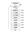
次いで、本実施の形態に係る画像形成装置において実行される重心計算法を用いたモータ速度制御処理について説明する。図22は、モータ速度制御処理のフローチャートである。   Next, motor speed control processing using the center of gravity calculation method executed in the image forming apparatus according to the present embodiment will be described. FIG. 22 is a flowchart of the motor speed control process.

モータ速度制御処理を開始すると、まず、DSP50がLED601を点灯させて中間転写ベルト31の表面にLED光を照射させ(ステップS211)。次いで、図23で後述する速度検出処理を行う(ステップS212)。速度制御処理を実行後、LED601を消灯させ(ステップS213)、転写ベルト駆動モータ56の目標速度を設定する(ステップS214)。ステップS214においては、速度検出制御処理において算出された中間転写ベルト31の平均相対速度に応じて中間転写ベルト31の走行速度が目標走行速度となり一定の速度となるように転写ベルト駆動モータ56の目標速度を設定する。そして、転写ベルト駆動モータ56のサーボ制御処理を行う(ステップS215)。ステップS215において行うモータサーボ制御は、上記第1の実施の形態のモータサーボ制御処理(図16)と同様であるので説明は省略する。   When the motor speed control process is started, first, the DSP 50 turns on the LED 601 to irradiate the surface of the intermediate transfer belt 31 with LED light (step S211). Next, speed detection processing described later with reference to FIG. 23 is performed (step S212). After executing the speed control process, the LED 601 is turned off (step S213), and the target speed of the transfer belt drive motor 56 is set (step S214). In step S214, the target of the transfer belt drive motor 56 is set so that the traveling speed of the intermediate transfer belt 31 becomes the target traveling speed and becomes constant according to the average relative speed of the intermediate transfer belt 31 calculated in the speed detection control process. Set the speed. Then, servo control processing of the transfer belt drive motor 56 is performed (step S215). The motor servo control performed in step S215 is the same as the motor servo control process (FIG. 16) of the first embodiment, and a description thereof will be omitted.

次いで、図22のモータ速度制御処理のステップS212において実行する転写ベルト駆動モータ56の速度を検出する速度検出処理について説明する。図23は、図22のモータ速度制御処理のステップS202において実行される速度検出処理のフローチャートである。   Next, the speed detection process for detecting the speed of the transfer belt drive motor 56 executed in step S212 of the motor speed control process of FIG. 22 will be described. FIG. 23 is a flowchart of the speed detection process executed in step S202 of the motor speed control process of FIG.

まず、クロック信号S2に基づいてサンプリング周期(例えば、1ms)を決定するための割り込み信号を監視し(ステップS221)、割り込み信号を受信しない場合は本処理を終了する。一方、割り込み信号を受信した場合は、CMOSセンサ602によって中間転写ベルト31の表面状態を読み込んで表面画像(例えば図10の画像72)を作成する(ステップS222)。次いで、ステップS212において作成した表面画像をA/Dコンバータ612によってA/D変換し、CMOSセンサ602が検出した表面状態から最適な表面画像を作成できるようにフィルタ回路613のゲインを調整する(ステップS223)。次いで、フィルタ回路613において表面画像に対してフィルタ処理を行う(ステップS224)。このフィルタ処理によって、例えば、8ビット256階調データを16階調へ落とし、検出データからノイズ等による成分を除去する。そして、サンプリング制御部501によって、フィルタ処理された表面画像をサンプリングする。   First, an interrupt signal for determining a sampling period (for example, 1 ms) is monitored based on the clock signal S2 (step S221), and if no interrupt signal is received, this process ends. On the other hand, when an interrupt signal is received, the surface state of the intermediate transfer belt 31 is read by the CMOS sensor 602 to create a surface image (for example, the image 72 in FIG. 10) (step S222). Next, the surface image created in step S212 is A / D converted by the A / D converter 612, and the gain of the filter circuit 613 is adjusted so that an optimum surface image can be created from the surface state detected by the CMOS sensor 602 (step S212). S223). Next, the filter circuit 613 performs filter processing on the surface image (step S224). By this filter processing, for example, 8-bit 256 gradation data is reduced to 16 gradations, and components due to noise or the like are removed from the detection data. Then, the filtered surface image is sampled by the sampling control unit 501.

次いで、サンプリング制御部501によってサンプリングされたサンプリング画像(表面画像73)に対して上述のように2値化処理を行って2値化画像(図20,21参照)を作成する(ステップS225)。そして、上述した重心計算法により、作成した2値化画像の重心を算出する(ステップS226)(図22参照)。このとき、算出した2値化画像の重心値を画像メモリ153に格納する。次いで、前回の処理において算出された重心値と今回の処理において算出した重心値の差と、サンプリング時間から相対速度を導く(ステップS227)。次いで、予め設定された所定の期間にステップS227において算出された中間転写ベルト31の相対速度の算出結果の平均処理を行って、中間転写ベルト31の平均相対速度を算出する(ステップS228)。そして、算出した平均相対速度を画像メモリ153に記憶し(ステップS229)、一連の相対速度検出制御を終了する。   Next, binarization processing is performed on the sampling image (surface image 73) sampled by the sampling control unit 501 as described above to create a binarized image (see FIGS. 20 and 21) (step S225). Then, the center of gravity of the created binarized image is calculated by the above-described center of gravity calculation method (step S226) (see FIG. 22). At this time, the calculated centroid value of the binarized image is stored in the image memory 153. Next, a relative speed is derived from the difference between the centroid value calculated in the previous process and the centroid value calculated in the current process, and the sampling time (step S227). Next, an average process of the calculation result of the relative speed of the intermediate transfer belt 31 calculated in step S227 is performed during a predetermined period set in advance to calculate the average relative speed of the intermediate transfer belt 31 (step S228). Then, the calculated average relative speed is stored in the image memory 153 (step S229), and a series of relative speed detection control ends.

尚、寄り制御処理についても、上記モータ速度制御処理と同様に、第1の実施の形態における寄り制御処理に対してパターンマッチングではなく2値化データに基づく重心計算法によって中間転写ベルト31の寄り量を算出し、ステアリングモータ制御処理を実行する。このため、詳細な説明は省略する。   As for the shift control process, as in the motor speed control process, the shift of the intermediate transfer belt 31 is performed by a center of gravity calculation method based on binarized data instead of pattern matching as compared with the shift control process in the first embodiment. The amount is calculated and a steering motor control process is executed. For this reason, detailed description is omitted.

以上、説明したように本発明の第3の実施の形態に係る画像形成装置は、CMOSセンサ602を用いて中間転写ベルト31の表面状態を所定のサンプリング周期で検出して表面画像を作成する。そして、DSP50が、サンプリングした表面画像の重心を算出し、この重心値と、前回サンプリングされた表面画像の重心値とから、中間転写ベルト31の相対速度、及び寄り量を算出する。そして、算出した相体速度が0となるよう、つまり転写ベルト駆動モータ56の回転速度が目標速度になるように転写ベルト駆動モータ56の回転制御を行ってサーボ制御を行う。また、算出した中間転写ベルト31の寄り量が所定の範囲内になるようにステアリングモータ81を駆動制御して中間転写ベルト31の寄り方向の位置調整を行う。これにより、装置内の温度上昇によって転写ベルト駆動ローラ32が膨張しても上記サーボ制御によって転写ベルト駆動ローラ56の回転速度が目標速度に制御される。このため、中間転写ベルト31の走行速度が一定の速度(目標走行速度)に制御され、装置内の温度上昇に伴う色ずれや画像ぶれを低減させ、高品質画像を得ることができる。加えて、寄り制御を行うので、色ずれや画像ぶれをさらに低減させて、より高品質な画像を得ることができる。   As described above, the image forming apparatus according to the third embodiment of the present invention uses the CMOS sensor 602 to detect the surface state of the intermediate transfer belt 31 at a predetermined sampling period and create a surface image. Then, the DSP 50 calculates the center of gravity of the sampled surface image, and calculates the relative speed and shift amount of the intermediate transfer belt 31 from this center of gravity value and the center of gravity value of the surface image sampled last time. Then, the servo control is performed by controlling the rotation of the transfer belt drive motor 56 so that the calculated phase speed becomes 0, that is, the rotation speed of the transfer belt drive motor 56 becomes the target speed. Further, the steering motor 81 is driven and controlled so that the calculated shift amount of the intermediate transfer belt 31 falls within a predetermined range, thereby adjusting the position of the intermediate transfer belt 31 in the shift direction. Thus, even if the transfer belt drive roller 32 expands due to a temperature rise in the apparatus, the rotation speed of the transfer belt drive roller 56 is controlled to the target speed by the servo control. For this reason, the running speed of the intermediate transfer belt 31 is controlled to a constant speed (target running speed), color shift and image blur due to temperature rise in the apparatus can be reduced, and a high quality image can be obtained. In addition, since shift control is performed, color shift and image blur can be further reduced, and a higher quality image can be obtained.

尚、上記第3の実施の形態における重心算出法に基づくモータ速度制御処理及び寄り制御処理は、上記第2の実施の形態に係る中間転写体を備えない画像形成装置に対しても適用することができる。   Note that the motor speed control process and the shift control process based on the center-of-gravity calculation method in the third embodiment are also applied to an image forming apparatus that does not include the intermediate transfer member according to the second embodiment. Can do.

また、本発明の目的は、前述した各実施の形態の機能を実現するソフトウェアのプログラムコードを記憶した記憶媒体を、システム或いは装置に供給し、そのシステム或いは装置のコンピュータ(またはCPUやMPU等)が記憶媒体に格納されたプログラムコードを読み出し実行することによっても達成される。   Another object of the present invention is to supply a storage medium storing software program codes for realizing the functions of the above-described embodiments to a system or apparatus, and the computer of the system or apparatus (or CPU, MPU, or the like). Is also achieved by reading and executing the program code stored in the storage medium.

この場合、記憶媒体から読み出されたプログラムコード自体が前述した各実施の形態の機能を実現することになり、そのプログラムコード及び該プログラムコードを記憶した記憶媒体は本発明を構成することになる。   In this case, the program code itself read from the storage medium realizes the functions of the above-described embodiments, and the program code and the storage medium storing the program code constitute the present invention. .

また、プログラムコードを供給するための記憶媒体としては、例えば、フロッピー(登録商標)ディスク、ハードディスク、光磁気ディスク、CD−ROM、CD−R、CD−RW、DVD−ROM、DVD−RAM、DVD−RW、DVD+RW等の光ディスク、磁気テープ、不揮発性のメモリカード、ROM等を用いることができる。または、プログラムコードをネットワークを介してダウンロードしてもよい。   Examples of the storage medium for supplying the program code include a floppy (registered trademark) disk, a hard disk, a magneto-optical disk, a CD-ROM, a CD-R, a CD-RW, a DVD-ROM, a DVD-RAM, and a DVD. An optical disc such as RW or DVD + RW, a magnetic tape, a nonvolatile memory card, a ROM, or the like can be used. Alternatively, the program code may be downloaded via a network.

また、コンピュータが読み出したプログラムコードを実行することにより、前述した各実施の形態の機能が実現されるだけではなく、そのプログラムコードの指示に基づき、コンピュータ上で稼動しているOS(オペレーティングシステム)等が実際の処理の一部または全部を行い、その処理によって前述した各実施の形態の機能が実現される場合も含まれる。   Further, by executing the program code read by the computer, not only the functions of the above-described embodiments are realized, but also an OS (Operating System) running on the computer based on the instruction of the program code Includes a case where the functions of the above-described embodiments are realized by performing part or all of the actual processing.

さらに、記憶媒体から読み出されたプログラムコードが、コンピュータに挿入された機能拡張ボードやコンピュータに接続された機能拡張ユニットに備わるメモリに書き込まれた後、そのプログラムコードの指示に基づき、その拡張機能を拡張ボードや拡張ユニットに備わるCPU等が実際の処理の一部または全部を行い、その処理によって前述した各実施の形態の機能が実現される場合も含まれる。   Furthermore, after the program code read from the storage medium is written to a memory provided in a function expansion board inserted into the computer or a function expansion unit connected to the computer, the expanded function is based on the instruction of the program code. This includes a case where a CPU or the like provided on the expansion board or the expansion unit performs part or all of the actual processing and the functions of the above-described embodiments are realized by the processing.

本発明の第1の実施の形態に係る画像形成装置の要部断面図である。1 is a cross-sectional view of a main part of an image forming apparatus according to a first embodiment of the present invention. 図1の画像形成装置における外ローラのアライメント調整機構の概略構成を示す斜視図である。FIG. 2 is a perspective view illustrating a schematic configuration of an outer roller alignment adjusting mechanism in the image forming apparatus of FIG. 1. 図1の画像形成装置の内部の電気的構成を示す回路ブロック図である。FIG. 2 is a circuit block diagram showing an internal electrical configuration of the image forming apparatus in FIG. 1. 図1の画像形成装置におけるDCモータユニットの構成を示すブロック図である。FIG. 2 is a block diagram illustrating a configuration of a DC motor unit in the image forming apparatus of FIG. 1. 図1の画像形成装置における画像センサユニットの概略構成を示す図である。FIG. 2 is a diagram illustrating a schematic configuration of an image sensor unit in the image forming apparatus of FIG. 1. 図5の画像センサユニットが作成する中間転写ベルトの表面画像の一例を示す図である。FIG. 6 is a diagram illustrating an example of a surface image of an intermediate transfer belt created by the image sensor unit of FIG. 5. 図5の画像センサユニットの概略構成を示す回路図である。FIG. 6 is a circuit diagram illustrating a schematic configuration of the image sensor unit of FIG. 5. 図5の画像センサユニットの回路動作を説明する図である。It is a figure explaining the circuit operation | movement of the image sensor unit of FIG. 図1の画像形成装置におけるDSPの概略構成を示すブロック図である。FIG. 2 is a block diagram illustrating a schematic configuration of a DSP in the image forming apparatus of FIG. 1. 図7の画像センサユニットによる中間転写ベルトの表面画像の検出方法を説明する図である。It is a figure explaining the detection method of the surface image of an intermediate transfer belt by the image sensor unit of FIG. 図5の画像センサユニットが作成する中間転写ベルトの表面画像、及び図9のDSPが作成するズラシ表面画像の一例を示す図である。FIG. 10 is a diagram illustrating an example of a surface image of an intermediate transfer belt created by the image sensor unit of FIG. 5 and a slip surface image created by the DSP of FIG. 9. 図5の画像センサユニットが作成する中間転写ベルトの表面画像、及び図9のDSPが作成するズラシ表面画像の一例を示す図である。FIG. 10 is a diagram illustrating an example of a surface image of an intermediate transfer belt created by the image sensor unit of FIG. 5 and a slip surface image created by the DSP of FIG. 9. 図5の画像センサユニットが作成する中間転写ベルトの表面画像、及び図9のDSPが作成するズラシ表面画像の一例を示す図である。FIG. 10 is a diagram illustrating an example of a surface image of an intermediate transfer belt created by the image sensor unit of FIG. 5 and a slip surface image created by the DSP of FIG. 9. 図9のDSPが実行するモータ速度制御処理のフローチャートである。10 is a flowchart of a motor speed control process executed by the DSP of FIG. 図14のモータ速度制御処理において実行される速度検出処理のフローチャートである。It is a flowchart of the speed detection process performed in the motor speed control process of FIG. 図14のモータ速度制御処理において実行されるモータサーボ制御処理のフローチャートである。It is a flowchart of the motor servo control process performed in the motor speed control process of FIG. 図9のDSPにおいて実行される中間転写ベルトの寄り制御処理のフローチャートである。10 is a flowchart of an intermediate transfer belt shift control process executed in the DSP of FIG. 9. 図17の寄り制御処理において実行される寄り量検出処理のフローチャートである。18 is a flowchart of a shift amount detection process executed in the shift control process of FIG. 本発明の第2の実施の形態に係る画像形成装置の概略構成を示す要部断面図である。It is principal part sectional drawing which shows schematic structure of the image forming apparatus which concerns on the 2nd Embodiment of this invention. 図5におけるCMOSセンサで読み込んだ中間転写ベルトの表面画像を2値化処理した後の表面画像を示す図である。FIG. 6 is a diagram showing a surface image after binarizing the surface image of the intermediate transfer belt read by the CMOS sensor in FIG. 5. 図20の2値化画像に基づいて重心計算した結果を示す表を示す図である。It is a figure which shows the table | surface which shows the result of having performed the gravity center calculation based on the binarized image of FIG. 図9のDSPにおいて実行されるモータ速度制御処理のフローチャートである。10 is a flowchart of a motor speed control process executed in the DSP of FIG. 図22のモータ速度制御処理において実行される速度検出処理のフローチャートである。It is a flowchart of the speed detection process performed in the motor speed control process of FIG. 従来のタンデムタイプの画像形成装置の一例を示す図である。It is a figure which shows an example of the conventional tandem type image forming apparatus.

符号の説明Explanation of symbols

1,200 画像形成装置
31 中間転写ベルト
32,227 転写ベルト駆動ロータ
50 DSP
51 CPU
56 転写ベルト駆動モータ
60 画像センサユニット
80 外ローラ
81 ステアリングモータ
205 転写ベルト
1,200 Image forming apparatus 31 Intermediate transfer belt 32, 227 Transfer belt drive rotor 50 DSP
51 CPU
56 Transfer belt drive motor 60 Image sensor unit 80 Outer roller 81 Steering motor 205 Transfer belt

Claims (26)

像担持体と、
前記像担持体上に形成された画像が一次転写される中間転写体と、
前記中間転写体の表面画像を読み取る表面読み取り手段と、
前記表面読み取り手段により読み取られた表面画像に基づいて、前記中間転写体の移動方向の速度及び前記移動方向に直交する幅方向の移動量を演算する演算手段と、
前記演算手段の演算結果に基づいて、前記中間転写体の前記移動方向及び前記幅方向の移動を制御する制御手段と、を有し、
前記表面読み取り手段により読み取られる画像領域は、前記中間転写体の前記移動方向の画素数よりも前記幅方向の画素数の方が多いことを特徴とする画像形成装置。
An image carrier;
An intermediate transfer member on which an image formed on the image carrier is primarily transferred;
Surface reading means for reading a surface image of the intermediate transfer member;
Based on the surface image read by the surface reading means, calculating means for calculating the speed in the moving direction of the intermediate transfer member and the moving amount in the width direction orthogonal to the moving direction;
Control means for controlling the movement of the intermediate transfer member in the movement direction and the width direction based on the calculation result of the calculation means ;
The image forming apparatus according to claim 1, wherein the number of pixels in the width direction is larger than the number of pixels in the moving direction of the intermediate transfer body in the image area read by the surface reading unit .
前記中間転写体を駆動する中間転写体駆動モータをさらに備え、
前記制御手段は、前記演算手段により演算された前記中間転写体の移動方向の速度に応じて前記中間転写体駆動モータを制御することを特徴とする請求項1記載の画像形成装置。
An intermediate transfer member drive motor for driving the intermediate transfer member;
The image forming apparatus according to claim 1, wherein the control unit controls the intermediate transfer member driving motor according to a speed in a moving direction of the intermediate transfer member calculated by the calculating unit.
前記中間転写体の前記幅方向の移動を制御するための寄り駆動モータをさらに備え、
前記制御手段は、前記演算手段により演算された前記中間転写体の前記幅方向の移動量に応じて前記寄り駆動モータを制御することを特徴とする請求項1又は2記載の画像形成装置。
A displacement drive motor for controlling the movement of the intermediate transfer member in the width direction;
The image forming apparatus according to claim 1, wherein the control unit controls the shift driving motor in accordance with a movement amount of the intermediate transfer member in the width direction calculated by the calculation unit.
前記表面読み取り手段は、前記中間転写体の表面画像データを作成する画像作成部材と、前記中間転写体に光を照射する照明部材と、前記照明部材により照射され前記中間転写体から反射された光を前記画像作成部材へ結像させる結像レンズとを備えることを特徴とする請求項1乃至3のいずれか1項に記載の画像形成装置。   The surface reading means includes an image creating member that creates surface image data of the intermediate transfer member, an illumination member that irradiates light to the intermediate transfer member, and light that is irradiated by the illumination member and reflected from the intermediate transfer member. An image forming apparatus according to claim 1, further comprising: an imaging lens that forms an image on the image forming member. 前記表面読み取り手段が読み取った前記中間転写体の表面画像を一定周期でサンプリングするサンプリング手段と、前記サンプリング手段にサンプリングされた画像を少なくとも1画像分記憶する画像記憶手段とを備え、
前記演算手段は、前記サンプリング手段によりサンプリングされた画像及び前記画像記憶手段に記憶された画像に基づいて前記中間転写体の移動方向の速度及び前記幅方向の移
動量を演算することを特徴とする請求項1乃至4のいずれか1項に記載の画像形成装置。
Sampling means for sampling the surface image of the intermediate transfer body read by the surface reading means at a constant period, and image storage means for storing at least one image sampled by the sampling means,
The computing means computes the speed in the moving direction and the moving amount in the width direction of the intermediate transfer member based on the image sampled by the sampling means and the image stored in the image storage means. The image forming apparatus according to claim 1.
前記演算手段は、前記サンプリングされた画像及び前回の前記サンプリングされた画像に対して相対比較演算を行うことによって前記中間転写体の移動方向の相対速度を算出することを特徴とする請求項5記載の画像形成装置。   6. The calculation unit according to claim 5, wherein the calculation unit calculates a relative speed in the moving direction of the intermediate transfer member by performing a relative comparison calculation on the sampled image and the previous sampled image. Image forming apparatus. 前記制御手段は、前記演算手段によって算出された前記相対速度に基づいて前記中間転写体の移動速度が一定速度となるように制御することを特徴とする請求項6記載の画像形成装置。   The image forming apparatus according to claim 6, wherein the control unit controls the moving speed of the intermediate transfer member to be a constant speed based on the relative speed calculated by the calculating unit. 前記演算手段は、前記サンプリング手段によりサンプリングされた前記中間転写体の表面画像の重心を前記サンプリング毎に算出し、前記算出された表面画像の重心の遷移データの相対比較演算を行うことによって前記中間転写体の移動方向の速度及び前記幅方向の移動量を算出することを特徴とする請求項5記載の画像形成装置。   The computing means calculates the center of gravity of the surface image of the intermediate transfer member sampled by the sampling means for each sampling, and performs a relative comparison operation of the calculated transition data of the center of gravity of the surface image. 6. The image forming apparatus according to claim 5, wherein a speed in the moving direction of the transfer body and a moving amount in the width direction are calculated. 前記制御手段は、前記演算手段により演算された前記移動量に基づいて前記中間転写体の寄りが一定範囲となるように前記寄り駆動モータを制御することを特徴とする請求項3記載の画像形成装置。   4. The image forming apparatus according to claim 3, wherein the control unit controls the shift driving motor so that the shift of the intermediate transfer member is within a certain range based on the movement amount calculated by the calculation unit. apparatus. 前記演算手段は、前記表面読み取り手段によって形成された前記中間転写体の表面画像をフィルタ処理するフィルタ演算部を備えることを特徴とする請求項1乃至9のいずれか1項に記載の画像形成装置。   The image forming apparatus according to claim 1, wherein the calculation unit includes a filter calculation unit configured to filter a surface image of the intermediate transfer body formed by the surface reading unit. . 前記演算手段は、前記フィルタ演算部のフィルタ定数を可変制御するフィルタ定数制御部を備えることを特徴とする請求項10記載の画像形成装置。   The image forming apparatus according to claim 10, wherein the calculation unit includes a filter constant control unit that variably controls a filter constant of the filter calculation unit. 前記照明部材は、照射光の光量を可変制御する照明光量制御手段を備えることを特徴とする請求項4記載の画像形成装置。   The image forming apparatus according to claim 4, wherein the illumination member includes illumination light amount control means for variably controlling the amount of irradiation light. 前記表面読み取り手段は、前記画像作成部材としての複数の画素を備えたCCDセンサ及びCMOSセンサの一方と、前記CCDセンサ及び前記CMOSセンサの一方からのアナログ信号をデジタル信号へ変換するA/D変換部とを備えることを特徴とする請求項4記載の画像形成装置。   The surface reading means includes one of a CCD sensor and a CMOS sensor having a plurality of pixels as the image forming member, and an A / D conversion for converting an analog signal from one of the CCD sensor and the CMOS sensor into a digital signal. The image forming apparatus according to claim 4, further comprising: an image forming unit. 転写材を搬送するための転写材担持体と、
前記転写材及び前記転写材担持体の一方の表面画像を読み取る表面読み取り手段と、
前記表面読み取り手段により読み取られた表面画像に基づいて、前記転写材及び前記転写材担持体の一方の移動方向の速度及び前記移動方向に直交する幅方向の移動量を演算する演算手段と、
前記演算手段の演算結果に基づいて、前記転写材及び前記転写材担持体の一方の前記移動方向及び前記幅方向の移動を制御する制御手段と、を有し、
前記表面読み取り手段により読み取られる画像領域は、前記転写材担持体の前記移動方向の画素数よりも前記幅方向の画素数の方が多いことを特徴とする画像形成装置。
A transfer material carrier for conveying the transfer material;
Surface reading means for reading one surface image of the transfer material and the transfer material carrier;
Based on the surface image read by the surface reading means, calculation means for calculating the speed in one movement direction of the transfer material and the transfer material carrier and the movement amount in the width direction orthogonal to the movement direction;
Control means for controlling movement of one of the transfer material and the transfer material carrier in the movement direction and the width direction based on the calculation result of the calculation means ;
The image forming apparatus according to claim 1, wherein the number of pixels in the width direction is larger than the number of pixels in the moving direction of the transfer material carrier in the image area read by the surface reading unit .
前記転写材担持体を駆動する転写材担持体駆動モータをさらに備え、
前記制御手段は、前記演算手段により演算された前記転写材及び前記転写材担持体の一方の移動方向の速度に応じて前記転写材担持体駆動モータの回転速度を制御することを特徴とする請求項14記載の画像形成装置。
A transfer material carrier driving motor for driving the transfer material carrier;
The control means controls a rotation speed of the transfer material carrier driving motor in accordance with a speed in one moving direction of the transfer material and the transfer material carrier calculated by the calculating means. Item 15. The image forming apparatus according to Item 14.
前記転写材担持体の前記移動方向に直交する幅方向の移動を制御するための寄り駆動モータをさらに備え、
前記制御手段は、前記演算手段により演算された前記転写材及び前記転写材担持体の一方の移動方向に直行する幅方向の移動量に応じて前記寄り駆動モータを制御することを特徴とする請求項14又は15記載の画像形成装置。
A shift drive motor for controlling the movement of the transfer material carrier in the width direction perpendicular to the movement direction;
The control means controls the shift drive motor according to a movement amount in a width direction orthogonal to one movement direction of the transfer material and the transfer material carrier calculated by the calculation means. Item 14. The image forming apparatus according to Item 14 or 15.
前記表面読み取り手段は、前記転写材及び前記転写材担持体の一方の表面画像データを作成する画像作成部材と、前記転写材及び前記転写材担持体の一方の表面に光を照射する照明部材と、前記照明部材により照射され前記転写材及び前記転写材担持体の一方から反射された光を前記画像作成部材へ結像させる結像レンズとを備えることを特徴とする請求項14乃至16のいずれか1項に記載の画像形成装置。   The surface reading means includes an image creating member that creates one surface image data of the transfer material and the transfer material carrier, and an illumination member that irradiates light to one surface of the transfer material and the transfer material carrier; An imaging lens that forms an image on the image forming member with light irradiated from the illumination member and reflected from one of the transfer material and the transfer material carrier. The image forming apparatus according to claim 1. 前記表面読み取り手段が読み取った前記転写材及び前記転写材担持体の一方の表面画像を一定周期でサンプリングするサンプリング手段と、前記サンプリング手段にサンプリングした画像を少なくとも1画像分記憶する画像記憶手段とを備え、
前記演算手段は、前記サンプリング手段によりサンプリングされた画像及び前記画像記憶手段に記憶された画像に基づいて前記転写材及び前記転写材担持体の一方の移動方向の速度及び前記移動方向に直行する幅方向の移動量を演算することを特徴とする請求項14乃至17のいずれか1項に記載の画像形成装置。
Sampling means for sampling one surface image of the transfer material and the transfer material carrier read by the surface reading means, and an image storage means for storing at least one sampled image in the sampling means. Prepared,
The calculating means is configured to determine a speed in one moving direction of the transfer material and the transfer material carrier and a width orthogonal to the moving direction based on the image sampled by the sampling means and the image stored in the image storage means. The image forming apparatus according to claim 14, wherein a movement amount in the direction is calculated.
前記演算手段は、前記サンプリングされた画像及び前回の前記サンプリングされた画像に対して相対比較演算を行うことによって前記転写材及び前記転写材担持体の一方の移動方向の相対速度を算出することを特徴とする請求項18記載の画像形成装置。   The arithmetic means calculates a relative speed in one moving direction of the transfer material and the transfer material carrier by performing a relative comparison operation on the sampled image and the previous sampled image. The image forming apparatus according to claim 18. 前記制御手段は、前記演算手段によって算出された前記相対速度に基づいて前記転写材及び前記転写材担持体の一方の移動速度が一定速度となるように制御することを特徴とする請求項19記載の画像形成装置。   The control means controls the movement speed of one of the transfer material and the transfer material carrier to be a constant speed based on the relative speed calculated by the calculation means. Image forming apparatus. 前記演算手段は、前記サンプリング手段によりサンプリングされた前記転写材及び前記転写材担持体の一方の表面画像の重心を前記サンプリング毎に演算し、前記演算された表面画像の重心の遷移データの相対比較演算を行うことによって前記転写材及び前記転写材担持体の一方の移動方向の速度及び前記幅方向の移動量を算出することを特徴とする請求項18記載の画像形成装置。   The calculation means calculates the center of gravity of one surface image of the transfer material and the transfer material carrier sampled by the sampling means for each sampling, and performs a relative comparison of the calculated transition data of the center of gravity of the surface image 19. The image forming apparatus according to claim 18, wherein a speed in one movement direction and a movement amount in the width direction of the transfer material and the transfer material carrier are calculated by performing an operation. 前記制御手段は、前記演算手段により演算された前記移動量に基づいて前記転写材担持体の寄りが一定範囲となるように前記寄り駆動モータを制御することを特徴とする請求項16記載の画像形成装置。   17. The image according to claim 16, wherein the control unit controls the shift driving motor so that a shift of the transfer material carrier is within a certain range based on the movement amount calculated by the calculation unit. Forming equipment. 前記演算手段は、前記表面読み取り手段によって形成された前記転写材及び前記転写材担持体の一方の表面画像をフィルタ処理するフィルタ演算部を備えることを特徴とする請求項16記載の画像形成装置。   The image forming apparatus according to claim 16, wherein the calculation unit includes a filter calculation unit configured to filter one surface image of the transfer material and the transfer material carrier formed by the surface reading unit. 前記演算手段は、前記フィルタ演算部のフィルタ定数を可変制御するフィルタ定数制御部を備えることを特徴とする請求項23記載の画像形成装置。   24. The image forming apparatus according to claim 23, wherein the calculation unit includes a filter constant control unit that variably controls a filter constant of the filter calculation unit. 前記照明部材は、照射光の光量を可変制御する照明光量制御手段を備えることを特徴とする請求項17記載の画像形成装置。   The image forming apparatus according to claim 17, wherein the illumination member includes an illumination light amount control unit that variably controls the amount of irradiation light. 前記表面読み取り手段は、前記画像作成部材としての複数の画素を備えたCCDセンサ及びCMOSセンサの一方と、前記CCDセンサ及び前記CMOSセンサの一方からのアナログ信号をデジタル信号へ変換するA/D変換部とを備えることを特徴とする請求項17記載の画像形成装置。   The surface reading means includes one of a CCD sensor and a CMOS sensor having a plurality of pixels as the image forming member, and an A / D conversion for converting an analog signal from one of the CCD sensor and the CMOS sensor into a digital signal. The image forming apparatus according to claim 17, further comprising: an image forming unit.
JP2006098770A 2006-03-31 2006-03-31 Image forming apparatus Expired - Fee Related JP5058506B2 (en)

Priority Applications (5)

Application Number Priority Date Filing Date Title
JP2006098770A JP5058506B2 (en) 2006-03-31 2006-03-31 Image forming apparatus
EP07006273A EP1840665A2 (en) 2006-03-31 2007-03-27 Image forming apparatus
US11/692,994 US7796928B2 (en) 2006-03-31 2007-03-29 Image forming apparatus
CNB2007100914648A CN100549863C (en) 2006-03-31 2007-03-30 Image processing system
KR1020070031860A KR100955177B1 (en) 2006-03-31 2007-03-30 Image forming apparatus

Applications Claiming Priority (1)

Application Number Priority Date Filing Date Title
JP2006098770A JP5058506B2 (en) 2006-03-31 2006-03-31 Image forming apparatus

Publications (3)

Publication Number Publication Date
JP2007272021A JP2007272021A (en) 2007-10-18
JP2007272021A5 JP2007272021A5 (en) 2009-04-02
JP5058506B2 true JP5058506B2 (en) 2012-10-24

Family

ID=38197677

Family Applications (1)

Application Number Title Priority Date Filing Date
JP2006098770A Expired - Fee Related JP5058506B2 (en) 2006-03-31 2006-03-31 Image forming apparatus

Country Status (5)

Country Link
US (1) US7796928B2 (en)
EP (1) EP1840665A2 (en)
JP (1) JP5058506B2 (en)
KR (1) KR100955177B1 (en)
CN (1) CN100549863C (en)

Families Citing this family (15)

* Cited by examiner, † Cited by third party
Publication number Priority date Publication date Assignee Title
JP5233027B2 (en) * 2006-07-31 2013-07-10 オセ−テクノロジーズ・ベー・ヴエー Detection apparatus and method for image-to-sheet positioning
JP4845656B2 (en) * 2006-09-14 2011-12-28 キヤノン株式会社 Image forming apparatus
JP5558736B2 (en) * 2008-05-27 2014-07-23 キヤノン株式会社 Image forming apparatus and control method thereof
JP5536990B2 (en) * 2008-05-27 2014-07-02 キヤノン株式会社 Image forming apparatus
JP5252995B2 (en) 2008-05-27 2013-07-31 キヤノン株式会社 Image forming apparatus
JP4766140B2 (en) * 2009-03-27 2011-09-07 富士ゼロックス株式会社 Deviation correction apparatus, intermediate transfer apparatus, transfer apparatus, and image forming apparatus
US8351831B2 (en) * 2009-03-27 2013-01-08 Fuji Xerox Co., Ltd. Displacement correcting device, intermediate transfer device, transfer device, and image forming apparatus
JP5586919B2 (en) * 2009-10-30 2014-09-10 キヤノン株式会社 Movement detection apparatus and recording apparatus
JP5586918B2 (en) * 2009-10-30 2014-09-10 キヤノン株式会社 Movement detection apparatus and recording apparatus
JP2011133870A (en) * 2009-11-27 2011-07-07 Canon Inc Image forming device and control method therefor
JP5506458B2 (en) * 2010-03-04 2014-05-28 キヤノン株式会社 Image forming apparatus
JP5949251B2 (en) * 2012-07-17 2016-07-06 株式会社リコー Moving member detection apparatus and image forming apparatus
JP6661311B2 (en) 2015-09-11 2020-03-11 キヤノン株式会社 Image heating device and heater used in image heating device
CN113135029B (en) * 2021-04-28 2023-04-25 蓝思科技(长沙)有限公司 Printing apparatus and printing method thereof
CN113135021B (en) * 2021-04-28 2023-04-25 蓝思科技(长沙)有限公司 Transfer printing apparatus and printing method thereof

Family Cites Families (18)

* Cited by examiner, † Cited by third party
Publication number Priority date Publication date Assignee Title
US4705386A (en) * 1986-05-12 1987-11-10 Shinko Electric Co., Ltd. Color copying machine
DE3834232A1 (en) * 1987-10-09 1989-04-20 Brother Ind Ltd DEVICE AND METHOD FOR RECORDING A COLOR IMAGE
JP2875261B2 (en) * 1988-08-05 1999-03-31 キヤノン株式会社 Image forming device
DE3933196C2 (en) * 1989-10-05 1994-05-26 Schenck Ag Carl Method and device for monitoring the belt run of a conveyor belt or a belt scale
JPH0844134A (en) * 1994-07-26 1996-02-16 Fuji Xerox Co Ltd Multiple image forming device
JP2765628B2 (en) * 1996-03-07 1998-06-18 株式会社リコー Image forming device
JPH11160952A (en) * 1997-11-21 1999-06-18 Canon Inc Image forming device
JP2000071522A (en) 1998-09-02 2000-03-07 Minolta Co Ltd Image-forming apparatus
JP2000089529A (en) * 1998-09-10 2000-03-31 Minolta Co Ltd Image forming device
US6137517A (en) * 1999-04-14 2000-10-24 Xerox Corporation Image registration adjustment system and method for dynamically compensating for photoreceptor belt skew
JP2001039523A (en) * 1999-08-03 2001-02-13 Nec Niigata Ltd Belt traveling control mechanism and image forming device provided with the belt traveling control mechanism
EP1203269B1 (en) * 1999-08-10 2007-03-21 Océ Printing Systems GmbH Method and controlling means for regulating the position of a band-shaped image carrier in an electrographic apparatus
JP2002202705A (en) * 2000-12-28 2002-07-19 Canon Inc Imaging device
US20030011795A1 (en) * 2001-06-27 2003-01-16 Bobo Wang Belt control means for an image forming apparatus
JP2004094177A (en) * 2002-04-26 2004-03-25 Canon Inc Electrophotographic endless belt, process cartridge, and electrophotographic system
JP4021717B2 (en) 2002-06-21 2007-12-12 株式会社リコー Image forming apparatus
JP2004184468A (en) 2002-11-29 2004-07-02 Canon Inc Color image forming apparatus
JP2004280016A (en) 2003-03-19 2004-10-07 Ricoh Co Ltd Intermediate transfer device and image forming apparatus, moving speed correcting method for intermediate transfer body, and photoreceptor rotating speed correcting method

Also Published As

Publication number Publication date
KR100955177B1 (en) 2010-04-29
JP2007272021A (en) 2007-10-18
CN101046664A (en) 2007-10-03
KR20070098741A (en) 2007-10-05
US20070231021A1 (en) 2007-10-04
US7796928B2 (en) 2010-09-14
CN100549863C (en) 2009-10-14
EP1840665A2 (en) 2007-10-03

Similar Documents

Publication Publication Date Title
JP5058506B2 (en) Image forming apparatus
JP4058648B1 (en) Color image forming apparatus
JP4498216B2 (en) Color image forming apparatus and control method thereof
KR101522073B1 (en) Image forming apparatus capable of preventing belt from meandering
JP4355700B2 (en) Image forming apparatus and control method of the apparatus
KR100485552B1 (en) Image forming apparatus
JP4277880B2 (en) Image forming apparatus and test pattern
JP2003098795A (en) Image forming apparatus
JP4434410B2 (en) Image forming apparatus
US20120114395A1 (en) Image forming apparatus and computer readable medium storing program
JP4720190B2 (en) Image forming apparatus
JP2002214864A (en) Image forming device
JP4298157B2 (en) Image forming apparatus
JP2008052200A (en) Image forming apparatus
JP4989201B2 (en) Color image forming apparatus and driving method of color image forming apparatus
JP3890228B2 (en) Image forming apparatus
JP2008107399A (en) Image forming apparatus
JP4818022B2 (en) Image forming apparatus and control method thereof
JP5241134B2 (en) Image forming apparatus
JP2006208668A (en) Image forming apparatus
JP4439663B2 (en) Image forming apparatus
JP4965929B2 (en) Image forming apparatus and control method thereof
JP2004205627A (en) Image forming apparatus
JP2007264302A (en) Image forming apparatus and control method
JP2007078831A (en) Belt conveying device, transfer device and color image forming apparatus

Legal Events

Date Code Title Description
A521 Request for written amendment filed

Free format text: JAPANESE INTERMEDIATE CODE: A523

Effective date: 20090217

A621 Written request for application examination

Free format text: JAPANESE INTERMEDIATE CODE: A621

Effective date: 20090217

A131 Notification of reasons for refusal

Free format text: JAPANESE INTERMEDIATE CODE: A131

Effective date: 20120110

A521 Request for written amendment filed

Free format text: JAPANESE INTERMEDIATE CODE: A523

Effective date: 20120224

TRDD Decision of grant or rejection written
A01 Written decision to grant a patent or to grant a registration (utility model)

Free format text: JAPANESE INTERMEDIATE CODE: A01

Effective date: 20120731

A01 Written decision to grant a patent or to grant a registration (utility model)

Free format text: JAPANESE INTERMEDIATE CODE: A01

A61 First payment of annual fees (during grant procedure)

Free format text: JAPANESE INTERMEDIATE CODE: A61

Effective date: 20120801

FPAY Renewal fee payment (event date is renewal date of database)

Free format text: PAYMENT UNTIL: 20150810

Year of fee payment: 3

FPAY Renewal fee payment (event date is renewal date of database)

Free format text: PAYMENT UNTIL: 20150810

Year of fee payment: 3

LAPS Cancellation because of no payment of annual fees