JP4439663B2 - Image forming apparatus - Google Patents
Image forming apparatus Download PDFInfo
- Publication number
- JP4439663B2 JP4439663B2 JP2000067987A JP2000067987A JP4439663B2 JP 4439663 B2 JP4439663 B2 JP 4439663B2 JP 2000067987 A JP2000067987 A JP 2000067987A JP 2000067987 A JP2000067987 A JP 2000067987A JP 4439663 B2 JP4439663 B2 JP 4439663B2
- Authority
- JP
- Japan
- Prior art keywords
- image
- correction
- image forming
- toner
- registration
- Prior art date
- Legal status (The legal status is an assumption and is not a legal conclusion. Google has not performed a legal analysis and makes no representation as to the accuracy of the status listed.)
- Expired - Fee Related
Links
Images


Description
【0001】
本発明は、複数の画像形成部それぞれが有する各色のトナーによって複数の画像担持体上それぞれに画像を形成し、前記複数の画像担持体上それぞれに形成された各色の画像を搬送される記録材の上に転写してカラー画像を形成する画像形成装置に関する。
【0002】
【従来の技術】
従来の複写機・プリンタ等のカラー画像形成装置においては、複数の画像形成部で形成されたトナー像を一旦中間転写体上に順次重ね合わせてから一括して記録材に転写する中間転写方式が知られている。
【0003】
【発明が解決しようとする課題】
しかしながら、フルカラー画像を得るために前記複数の画像形成部によって形成された画像を重ね合わせなければならない。
【0004】
そのため、予め画像形成を行う前に画像を重ね合わせるための調整を行う。
【0005】
この時、各々の画像形成部により中間転写体上にレジパターンを形成し、CCD等の検知手段であるレジセンサによって、各々の画像形成部で形成した中間転写体上のレジパターンを検知し、それによって画像合わせを行う必要があった。
【0006】
画像形成部の温度変化などによる主走査,副走査の画像書出しの位置のずれや倍率の変化やユニットの組み付け精度による画像の傾きなどを画像補正(以後、オートレジと呼ぶ)によって合わせる。
【0007】
この画像合わせ(以後、オートレジモードと呼ぶ)は画像形成装置の電源立ち上げ時、ジャム処理後のリスタート時、電源ON後所定時間経過時などに行なわれ、各色でレジパターンを打ち、それを検知しフィードバックをかけるために時間がかかり、このことにより画像形成装置の電源立ち上げ後のウェイトタイムが長くなったり、リスタートの時間がかかったりしてしまっていた。
【0008】
とくに連続画像形成時の温度上昇などにより、レーザスキャナなどの画像書き込み部、光学部品への歪みなどによる画像のずれを補正するために連続画像を所定枚数経過時、画像合わせモードに入って画像補正をかけていた。
【0009】
これによって画像形成の作業が度々中断され生産性が著しく低下してしまうという問題点があった。
【0010】
本発明は、上記の課題を解決するためになされたもので、本発明の目的は、連続画像形成中において画像補正にかかる処理時間を短縮して、生成性を低下することなく良好なカラー画像が得られる仕組みを提供することである。
【0011】
【課題を解決するための手段】
本発明は、複数の画像形成部それぞれが有する各色のトナーによって複数の画像担持体上それぞれにトナー像を形成し、前記複数の画像担持体上それぞれに形成されるトナー像を中間転写体を介して記録媒体上に転写することによってカラー画像を形成する画像形成装置において、前記中間転写体上に複数色のトナーそれぞれに対応する所定のトナーパターンを形成するために、前記画像形成部に前記所定のトナーパターンを前記複数の画像担持体上それぞれに形成させるパターン形成手段と、前記中間転写体上に転写された前記所定のトナーパターンの形成位置を検出する検出手段と、前記検出手段の検出結果に基づいて、前記記録媒体の搬送方向および前記搬送方向に直交する方向における前記複数色それぞれのトナー像の形成位置、前記搬送方向に直交する方向に対する前記トナー像の傾き、および前記トナー像の倍率を補正する第1の補正と、前記記録媒体の搬送方向および前記搬送方向に直交する方向における前記複数色それぞれのトナー像の形成位置を補正する第2の補正と、を実行する補正手段と、を有し、前記補正手段は、画像形成装置の電源がオンされた場合、または前記電源がオンされてから画像形成することなく所定時間経過した場合に前記第1の補正を実行し、前記画像形成部によって連続画像形成が開始されてから所定枚数の記録媒体に画像が形成された場合に前記第2の補正を実行し、前記補正手段は、前記第1の補正を実行する場合、前記検出手段によって検出された前記所定のトナーパターンの形成位置が所定の範囲に収まるまで前記第1の補正を繰り返し、前記第2の補正を実行する場合、前記第2の補正を繰り返さないことを特徴とする。
【0020】
【発明の実施の形態】
〔第1実施形態〕
図1は、本発明の第1実施形態を示す画像形成装置を適用可能な中間転写方式の画像形成装置の構成を説明する断面図である。
【0021】
以下、構成及び動作について説明する。
【0022】
図において、1Rは画像読み取り部で、原稿読み取り台に載置された原稿から画像データを読み取る。1Pは画像出力部で、画像読み取り部1R又は図示しない外部インタフェースを介して外部機器又はネットワーク等から入力される画像データに基づいて記録媒体(転写材P)上に画像形成を行う。
【0023】
画像出力部1Pは大別して、画像形成部10(4つのステーションa,b,c,dが並設されており、その構成は同一である)、給紙ユニット20,中間転写ユニット30,定着ユニット40及び不図示の制御ユニット(制御基板170,モータドライブ基板(不図示),外部インタフェース(不図示)等から成る)から構成される。
【0024】
さらに、個々のユニットについて詳しく説明する。
【0025】
画像形成部10は、以下に述べるような構成になっている。
【0026】
11a,11b,11c,11dは各々画像担持体としての感光ドラムで、その中心で軸支され、矢印方向に回転駆動される。感光ドラム11a,11b,11c,11dの外周面に対向してその回転方向に1次帯電器12a,12b,12c,12d,光学系13a,13b,13c,13d,現像装置14a,14b,14c,14dが配置されている。1次帯電器12a〜12dにおいて感光ドラム11a〜11dの表面に均一な帯電量の電荷を与える。
【0027】
次いで光学系13a〜13dにより、記録画像信号に応じて変調した例えばレーザビームなどの光線を感光ドラム11a〜11d上に露光させることによって、そこに静電潜像を形成する。さらに、イエロー(Y),マゼンタ(M),シアン(C),ブラック(BK)といった4色の現像剤(トナー)をそれぞれ収納した現像装置14a〜14dによって上記静電潜像を顕像化する。
【0028】
顕像化された可視画像を中間転写体(中間転写ベルト31)に転写する。画像転写領域Ta,Tb,Tc,Tdの下流側では、クリーニング装置15a,15b,15c,15dにより転写材に転写されずに感光ドラム11a〜11d上に残されたトナーを掻き落としてドラム表面の清掃を行う。
【0029】
以上に示したプロセスにより、イエロー(Y),マゼンタ(M),シアン(C),ブラック(BK)各トナーによる画像形成が順次行われる。
【0030】
給紙ユニット20は、記録材Pを収納するためのカセット21a,21bおよび手差しトレイ27、カセット内もしくは手差しトレイより記録材Pを一枚ずつ送り出すためのピックアップローラ22a,22bおよび26、各ピックアップローラから送り出された記録材Pをレジストローラまで搬送するための給紙ローラ対23及び給紙ガイド24、そして画像形成部の画像形成タイミングに合わせて記録材Pを2次転写領域Teへ送り出すためのレジストローラ25a,25bから成る。
【0031】
以下、中間転写ユニット30について説明する。
【0032】
中間転写ベルト31は、中間転写ベルト31に駆動を伝達する駆動ローラ32、ばね(不図示)の付勢によって中間転写ベルト31に適度な張力を与えるテンションローラ33、ベルトを挟んで2次転写領域Teに対向する従動ローラ34に巻回される。これらのうち駆動ローラ32とテンションローラ33の間に1次転写平面Aが形成される。駆動ローラ32は金属ローラの表面に数mm厚のゴム(ウレタンまたはクロロプレン)をコーティングしてベルトとのスリップを防いでいる。駆動ローラ32はパルスモータ(不図示)によって回転駆動される。各感光ドラム11a〜11dと中間転写ベルト31が対向する1次転写領域Ta〜Tdには、中間転写ベルト31の裏に1次転写ブレード35a〜35dが配置されている。
【0033】
従動ローラ34に対向して2次転写ローラ36が配置され、中間転写ベルト31とのニップによって2次転写領域Teを形成する。2次転写ローラ36は中間転写体に対して適度な圧力で加圧されている。また、中間転写ベルト31上、2次転写領域Teの下流には中間転写ベルト31の画像形成面をクリーニングするためのクリーニング装置50が配され、前記クリーニング装置50は、クリーナブレード51(材質としては、ポリウレタンゴムなどが用いられる)および廃トナーを収納する廃トナーボックス52から成る。
【0034】
定着ユニット40は、内部にハロゲンヒータなどの熱源を備えた定着ローラ41aとそのローラに加圧される定着ローラ41b(この定着ローラ41bにも熱源を備える場合もある)、及び上記ローラ対のニップ部へ転写材Pを導くためのガイド43、また、上記ローラ対から排出されてきた転写材Pをさらに装置外部に導き出すための内排紙ローラ44、外排紙ローラ45などから成る。
【0035】
制御ユニットは、上記各ユニット内の機構の動作を制御するための制御基板170や、モータドライブ基板(不図示)などから成る。
【0036】
次に装置の動作に即して説明を加える。
【0037】
画像形成動作開始信号が発せられると、まずピックアップローラ22aにより、カセット21aから転写材Pが一枚ずつ送り出される。そして給紙ローラ対23によって転写材Pが給紙ガイド24の間を案内されてレジストローラ25a,25bまで搬送される。その時レジストローラ25a,25bは停止されており、紙先端はニップ部に突き当たる。その後、画像形成部が画像の形成を開始するタイミングに合わせてレジストローラ25a,25bは回転を始める。この回転時期は、転写材Pと画像形成部より中間転写ベルト31上に1次転写されたトナー画像とが2次転写領域Teにおいてちょうど一致するようにそのタイミングが設定されている。
【0038】
一方画像形成部では、画像形成動作開始信号が発せられると、前述したプロセスにより中間転写ベルト31の回転方向において一番上流にある感光ドラム11d上に形成されたトナー画像が、高電圧が印加された1次転写用帯電器35dによって1次転写領域Tdにおいて中間転写ベルト31に1次転写される。1次転写されたトナー像は次の1次転写領域Tcまで搬送される。そこでは各画像形成部間をトナー像が搬送される時間だけ遅延して画像形成が行われており、前画像の上にレジストを合わせて次のトナー像が転写される事になる。以下も同様の工程が繰り返され、結局4色のトナー像が中間転写ベルト31上において1次転写される。
【0039】
その後記録材Pが2次転写領域Teに進入し、中間転写ベルト31に接触すると、記録材Pの通過タイミングに合わせて2次転写ローラ36に、高電圧を印加させる。そして前述したプロセスにより中間転写ベルト31上に形成された4色のトナー画像が記録材Pの表面に転写される。その後記録材Pは搬送ガイド43によって定着ローラニップ部まで正確に案内される。そして定着ローラ対41a、41bの熱及びニップの圧力によってトナー画像が記録材表面に定着される。その後、内外排紙ローラ44,45により搬送され、記録材Pは機外に排出される。
【0040】
また単色画像を得る場合は、特定の画像形成部(例えば中間転写体の進行方向最下流に位置する画像形成部d)より中間転写体上に単色の可視画像が1次転写され、以下フルカラー画像を形成する場合と同様のプロセスを経て、単色画像を得る。
【0041】
60は1対のレジセンサ(CCD又は、LED発光部とフォトセンサ受光部等により構成される光センサ等)で、中間転写ベルト31の両サイドに設けられ各画像形成部により中間転写ベルト31上に形成されたレジパターン(後述する図3に示す色ずれ検出パターン)を検出する。
【0042】
本発明の画像形成装置は、オートレジモードに入った時、各画像形成部のレジパターを検知手段であるレジセンサ60によって読み取り画像に対してフィードバックをかけレジ補正を行う制御手段としてのコントローラ1000(後述する図2に示す)を制御基板170内に有する。
【0043】
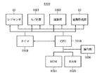
図2は、図1に示した制御基板170内に設けられたコントローラ1000の構成を説明するブロック図であり、図1と同一のものには同一の符号を付してある。
【0044】
図において、1021はA/D部(アナログデジタル変換部)で、レジセンサ60から出力されるアナログ信号(レジパターンの検出信号)をデジタル化する。
【0045】
1022は演算部で、A/D部1021によりデジタル化されたレジセンサ60からのデータを演算処理し、主走査方向位置ずれ量(主走査幅)及び補正値を算出する。画像形成部10は、演算部1022の演算結果に従って画像形成を行う。1018はCPUで、ROM1024又は図示しないその他の記憶媒体に格納されたプログラムに基づいて、画像形成装置全体を統括制御するとともに、各部のタイミング調整や各種設定を行う。
【0046】
1025はRAMで、CPU1018の作業領域として使用されるとともに、内部に不揮発性メモリを備え、画像形成装置の各種設定等を格納する。1019はタイマで、CPU1018の制御により、レジセンサ60がレジパターンを検出したタイミングを計時する。
【0047】
また、CPU1018は、ROM1024又は図示しないその他の記憶媒体に格納されるレジパターンデータに基づいて画像形成部10を制御して、後述する図3に示すレジパターンを中間転写ベルト31上に形成する。さらに、CPU1018は、演算部1022の算出結果に基づいて、画像形成部10による画像の書出しのタイミング、倍率、画像の傾きを調整等を制御して画像補正(オートレジ)を行う。
【0048】
図3は、本発明の画像形成装置のオートレジパターンを説明する模式図であり、図1と同一のものには同一の符号を付してある。
【0049】
図において、90Y,90M,90C,90BKはイエロー(Y),マゼンタ(M),シアン(C),ブラック(BK)各色のレジパターンで、各々中間転写ベルト31の移動方向左右両サイドに形成される一対のパターンにより構成される。
【0050】
このレジパターン90Y,90M,90C,90BKは、図2に示したCPU1018が画像形成部10(各色画像形成部により構成される)を制御することにより中間転写ベルト31上にそれぞれ形成される。
【0051】
このレジパターン90Y,90M,90C,90BKを各色画像形成部で中間転写ベルト31上に書出し、レジパターンの位置をレジセンサ60によって検知する。これによって、画像の書出しのタイミングや倍率、画像の傾きを調整することによってオートレジ(自動レジストレーション補正処理)を行う。
【0052】
図4は、本発明の画像形成装置のオートレジ処理を説明するためのレジパターンの模式図であり、図3と同一のものには同一の符号を付してある。
【0053】
図において、L1は基準となる画像形成部、例えばブラック(BK)画像形成部のレジパターン90BKを構成する一対のパターン間の距離であり、L2はブラック(BK)画像形成部以外の色(イエロー(Y),マゼンタ(M),シアン(C))の画像形成部のレジパターンを構成する一対のパターン間の距離である。
ΔHはブラック(BK)とブラック(BK)以外の色(イエロー(Y),マゼンタ(M),シアン(C))の主走査方向のパターン間の距離であり、画像書出し位置のずれ量に相当する。
【0054】
ΔV1,ΔV2はブラック(BK)とブラック(BK)以外の色(イエロー(Y),マゼンタ(M),シアン(C))の副走査方向のパターン間の距離である。
【0055】
以下、本発明の画像形成装置のオートレジルーチン(通常のレジストレーション補正処理)について説明する。なお、この通常のレジストレーション補正処理は、画像形成装置の電源立ち上げ後,所定時間電源ON後の放置時等に行われるものである。
【0056】
まず、レジパターン90Y,90M,90C,90BKを各色画像形成部で中間転写ベルト31上に書出し、レジパターンの位置をレジセンサ60によって検知し、基準となるブラック(BK)レジパターン90BKの距離L1と次の画像形成部(イエロー(Y),マゼンタ(M),シアン(C))のレジパターン(90Y,90M,90C)の距離L2を算出し、L1,L2を比較し、L1=L2になるようにL2の画像データ(イエロー(Y)画像データ,マゼンタ(M)画像データ,シアン(C)画像データ)を制御し画像の倍率を合わせる。
【0057】
次に、画像の書出し位置(主走査書出し、レフト補正)を行うためにΔHが「0」になるように主走査方向の書き出し位置を移動する。
【0058】
このあと倍率と画像書出しの補正されたレジパターンの画像を各画像形成部で中間転写ベルト31上に書き込む。
【0059】
次に、画像の傾きを補正する。
【0060】
これは距離ΔV1に距離ΔV2を合わせ基準となる画像形成部のレジパターン(ブラックレジパターン90BK)に合わせる。
【0061】
最後に画像先端位置を合わせるためにΔV1を所定の距離X、例えば画像形成部間隔になるように調整する。
【0062】
そしてまた、レジパターン90Y,90M,90C,90BKを中間転写ベルト31上に書き込み、レジセンサ60にてチェックをかける。
【0063】
レジ(レジストレーション)が合ってない場合は、このルーチンを何度か繰り返すことによって画像合わせを行い、精度を上げて行く。
【0064】
次に、連続画像形成で所定枚数経過時のレジストレーション補正処理について説明する。
【0065】
連続画像形成することによって機内の温度上昇によりレーザスキャナなどの画像書き込み部の光学部品などへの歪みの影響から画像ずれが発生してしまう。これを防止するために連続で所定枚数の画像形成を行ったところで画像補正を行う。この時行う画像補正は、温度上昇による影響が支配的でずれ量の大きくでてしまう先端ずれ(副走査方向の画像書出し位置ずれ)と画像の書き出し位置ずれ(主走査方向の画像書出し位置ずれ)の補正のみを行う。
【0066】
このモードにおけるレジパターンの間隔は通常のレジストレーション補正処理において画像先端位置を合わせるとき調整した所定距離Xの「1/n」(n:整数)とする。
【0067】
このモードにおけるレジパターンは上述した連続画像形成時の画像1フレーム分の中で行なわれ、画像の書出し位置(主走査書出し、レフト補正)を行うためにΔHが「0」になるように書き出し位置を移動する。
【0068】
次に、画像先端位置を合わせるためにΔV1を所定の距離Xの「1/n」になるように調整し、補正処理を終了する。
【0069】
これによって、簡易的にレジ合わせを行い、画像合わせを行って、短い時間でオートレジモードを入れる(自動レジストレーション補正を行う)ことができる。
【0070】
なお、この連続画像形成で所定枚数経過時のレジストレーション補正処理は、ジャム処理後のリスタート時にも行われるものとする。
【0071】
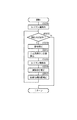
以下、図5のフローチャートを参照して、本発明の画像形成装置のレジストレーション補正処理について説明する。
【0072】
図5は、本発明の画像形成装置のレジストレーション補正処理の一例を示すフローチャートであり、図2に示したCPU1018がROM1024又は図示しないその他の記憶媒体に格納されたプログラムに基づいて実行する。なお、S101〜S104は各ステップを示す。
【0073】
まず、ステップS101において、電源を立ち上げた状態又は所定時間電源ON後、所定時間経過した状態であるか否かを判定し、電源を立ち上げた状態又は所定時間電源ON後、所定時間経過した状態であると判定された場合は、ステップS103において、第1の画像合せモード(補正項目をフルで実行する画像合せモード)によりレジストレーション補正(後述する図6に示す)を実行し、ステップS101の処理に戻る。
【0074】
一方、ステップS101で電源を立ち上げた状態又は所定時間電源ON後、所定時間経過した状態でないと判定された場合は、ステップS102において、連続画像形成時に所定枚数を経過した状態又はジャム処理後のリスタート状態であるかかを判定し、連続画像形成時に所定枚数を経過した状態又はジャム処理後のリスタート状態であると判定された場合は、ステップS104において、第2の画像合せモード(実行する補正項目を限定した画像合せモード)によりレジストレーション補正(後述する図7に示す)を実行し、ステップS101の処理に戻る。
【0075】
一方、ステップS102で連続画像形成時に所定枚数を経過した状態又はジャム処理後のリスタート状態でないと判定された場合は、そのままステップS101の処理に戻る。
【0076】
以下、図6,図7のフローチャートを参照して、本発明の画像形成装置のレジストレーション補正処理動作について説明する。
【0077】
図6は、本発明の画像形成装置の第1の画像合せモード(補正項目をフルで実行する画像合せモード)におけるレジストレーション補正処理手順について説明するフローチャートであり、電源を立ち上げた状態又は所定時間電源ON後、所定時間経過した状態の時に実行される。
【0078】
なお、この処理は、図2に示したCPU1018がROM1024又は図示しないその他の記憶媒体に格納されたプログラムに基づいて実行する。また、S201〜S207は各ステップを示す。
【0079】
まず、ステップS201において、第1の画像合せモードにおけるレジストレーション補正処理が開始されると、図3に示したレジパターン90Y,90M,90C,90BKを形成して中間転写ベルト31上に転写し、レジセンサ60によって読み取り、レジずれ量を検出する(各レジパターンの位置を検出し、L1,L2,ΔH,ΔV1,ΔV2を算出する)。
【0080】
次に、ステップS202において、ステップS201で検出した各レジパターン位置から補正の必要が有るか(L1とL2の差,ΔH,ΔV1,ΔV1とΔV2の差が所定の範囲に収まっているか)否かを判別し、必要が無い場合補正を行わずにレジストレーション補正処理をリターンする。
【0081】
一方、ステップS202で、補正の必要が有ると判定された場合は、ステップS203において、倍率補正を行い(L2をL1に合せ)、ステップS204において、ΔHが「0」となるように主走査方向の画像書出し位置補正を行い、ステップS205において、再度レジパターン90Y,90M,90C,90BKを形成して中間転写ベルト31上に転写し、レジセンサ60によって読み取り、レジずれ量を検出する(各レジパターンの位置を検出し、ΔV1,ΔV2を算出する)。
【0082】
次に、ステップS206において、画像の傾き補正を行い(ΔV2をΔV1に合せ)、ステップS207において、画像先端位置補正、即ち副走査方向の画像書出し位置補正を行い(ΔV1が各感光ドラムの間隔又は所定の距離Xとなるように合せ)、ステップS201の処理に戻る。
【0083】
図7は、本発明の画像形成装置の第2の画像合せモード(実行する補正項目を限定した画像合せモード)におけるレジストレーション補正処理手順について説明するフローチャートであり、連続画像形成時に所定枚数を経過した状態又はジャム処理後のリスタート状態の時に実行される。
【0084】
なお、この処理は、図2に示したCPU1018がROM1024又は図示しないその他の記憶媒体に格納されたプログラムに基づいて実行する。また、S301〜S304は各ステップを示す。
【0085】
まず、ステップS301において、第2の画像合せモードにおけるレジストレーション補正処理が開始されると、図3に示したレジパターン90Y,90M,90C,90BKを形成して中間転写ベルト31上に転写し、レジセンサ60によって読み取り、レジずれ量を検出する(各レジパターンの位置を検出し、ΔH,ΔV1を算出する)。
【0086】
次に、ステップS302において、ステップS301で検出した各レジパターン位置から補正の必要が有るか(ΔH,ΔV1が所定の範囲に収まっているか)否かを判別し、必要が無い場合補正を行わずにレジストレーション補正処理をリターンする。
【0087】
一方、ステップS302で、補正の必要が有ると判定された場合は、ステップS303において、ΔHが「0」となるように主走査方向の画像書出し位置補正を行い、ステップS304において、画像先端位置補正、即ち副走査方向の画像書出し位置補正を行い(ΔV1が上述した所定の距離X(例えば各感光ドラムの間隔)の「1/n」(nは整数)となるように合せ)、処理をリターンする。
【0088】
以上の処理により、連続画像形成時、主走査と副走査の書出しのレジ補正だけを簡易的に実行することにより、連続画像形成中に起こる画像補正の時間を短縮し、ダウンモードを短くして、生産性を上げるとともに良好な画質を提供することができる。
【0089】
〔第2実施形態〕
上記第1実施形態においては、複数の画像ステーションa〜dにより形成され一時的に転写される各画像を記録媒体に再転写する中間転写ベルト31上にレジパターンを形成してレジズレ量を検出する場合について説明したが、用紙等の記録媒体を搬送しつつ該記録媒体に対して複数の画像ステーションa〜dにより形成された各画像を感光ドラム11a〜11dから直接転写する転写ベルト上にレジパターンを形成してレジズレ量を検出するように構成してもよい。以下、その実施形態について説明する。
【0090】
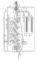
図8は、本発明の第2実施形態を示す画像形成装置の構成を説明する断面図であり、図1と同一のものには同一の符号を付してある。
【0091】
画像出力部1Pは大別して、画像形成部10、給紙ユニット20,転写ユニット70,定着ユニット40及び制御ユニット(不図示)から構成される。
【0092】
さらに、個々のユニットについて詳しく説明する。画像形成部10は次に述べるような構成になっている。
【0093】
以下、転写ユニット70について説明する。
【0094】
71は転写ベルトで、転写材Pを搬送しつつ転写材Pに対して画像転写領域Ta,Tb,Tc,Tdにおいて、現像装置14aから14dにより顕像化された感光ドラム11a〜11d上の可視画像を転写する。
【0095】
72は駆動ローラで、転写ベルト71に駆動を伝達する。この駆動ローラ72は金属ローラの表面に数mm厚のゴム(ウレタンまたはクロロプレン)をコーティングして転写ベルト71とのスリップを防いでいる。なお、駆動ローラ72は、パルスモータ(不図示)によって回転駆動される。
【0096】
74はテンシコンローラで、ばね(不図示)の付勢によって転写ベルト71に適度な張力を与える。
【0097】
75a〜75dは転写ブレードで、各感光ドラム11a〜11dと転写ベルト71とが対向する転写ベルト71上の転写領域Ta〜Tdの裏に配置される。
【0098】
50はクリーニング装置で、転写ベルト71上の転写領域Taの下流に配置され、転写ベルト71の画像形成面をクリーニングする。このクリーニング装置50は、クリーナブレード51および廃トナーを収納する廃トナーボックス52から構成される。
【0099】
以下、動作に即して説明を加える。
【0100】
画像形成動作開始信号が発せられると、まずピックアップローラ22aにより、カセット21aから転写材Pが一枚ずつ送り出される。そして、給紙ローラ対23によって転写材Pが給紙ガイド24の間を案内されてレジストローラ25a,25bまで搬送される。
【0101】
その時、レジストローラ25a,25bは停止されており、紙先端はニップ部に突き当たる。その後、画像形成部が画像の形成を開始するタイミングに合わせてレジストローラ25a,25bは回転を始める。この回転時期は、転写材Pと画像形成部のトナー像が転写部にてちょうど一致するようにそのタイミングが設定されている。
【0102】
一方、画像形成部10では、画像形成動作開始信号が発せられると、前述したプロセスにより転写ベルト71の回転方向において一番上流にある感光ドラム11d上に形成されたトナー画像が、高電圧が印加された転写ブレード75dによって転写領域Tdにおいて転写材Pに転写される。
【0103】
転写された転写材Pは、次の転写領域Tcまで搬送される。そこでは、各画像形成部間をトナー像が搬送される時間だけ遅延して画像形成が行われており、前画像の上にレジストを合わせて次のトナー像が転写される事になる。
【0104】
以下も同様の工程が繰り返され、結局4色のトナー像が転写材P上において転写される。
【0105】
その後、記録材Pは搬送ガイド43によって定着ローラニップ部まで正確に案内される。そして、ローラ対41a,41bの熱及びニップの圧力によってトナー画像が記録材表面に定着される。その後、内外排紙ローラ44,45により搬送され、記録材Pは機外に排出される。
【0106】
また、単色画像を得る場合は、特定の画像形成部(例えば転写ベルトの進行方向最下流に位置する画像形成部d)より転写材上に単色の可視画像が転写され、以下フルカラー画像を形成する場合と同様のプロセスを経て、単色画像を得る。
1対のレジセンサ(CCD又は、LED発光部とフォトセンサ受光部等により構成される光センサ等)60は、転写ベルト71の両サイドに設けられ各画像形成部により転写ベルト71上に形成されたレジパターン(図3に示した色ずれ検出パターン)を検出する。
【0107】
本発明の画像形成装置は、オートレジモードに入った時、各画像形成部のレジパタンを検知手段であるレジセンサ60によって読み取り画像に対してフィードバックをかけレジ補正を行う制御手段としてのコントローラ1000(上記第1実施形態と同様に図2に示したコントローラ)を制御基板170内に有する。
【0108】
本実施形態のオートレジパターンは、上記第1実施形態と同様に図3に示したようなものであり、このレジパターンを各画像形成部で転写ベルト71上に書出し、レジパターンの位置をレジセンサ60によって検知する。
【0109】
これによって画像の書出しのタイミングや倍率、画像の傾きを調整することによってオートレジ(自動レジストレーション補正処理)を行う。
【0110】
以下、図4を参照して、本実施形態の画像形成装置のオートレジルーチン(通常のレジストレーション補正処理)について説明する。なお、この通常のレジストレーション補正処理は、画像形成装置の電源立ち上げ後,所定時間電源ON後の放置時等に行われるものである。
【0111】
また、この通常のレジストレーション補正処理は、上述した第1実施形態において中間転写ベルト31上で行ったレジストレーションずれ検出を転写ベルト71上で行う点を除いては、上記第1実施形態と全く同様である。
【0112】
まず、レジパターン90Y,90M,90C,90BKを各色画像形成部で転写ベルト71上に転写し、該転写ベルト71上に転写されたレジパターンの位置をレジセンサ60によって検知し、基準となるブラック(BK)レジパターン90BKの距離L1と次の画像形成部(イエロー(Y),マゼンタ(M),シアン(C))のレジパターン(90Y,90M,90C)の距離L2を算出し、L1,L2を比較し、L1=L2になるようにL2の画像データ(イエロー(Y)画像データ,マゼンタ(M)画像データ,シアン(C)画像データ)を制御し画像の倍率を合わせる。
【0113】
次に、画像の書出し位置(主走査方向書出し、レフト補正)を行うためにΔHが「0」になるように主走査方向の書き出し位置を移動する。
【0114】
このあと倍率と画像書出しの補正されたレジパターンの画像を各画像形成部で転写ベルト71上に書き込む。
【0115】
次に、画像の傾きを補正する。
【0116】
これは距離ΔV1に距離ΔV2を合わせ基準となる画像形成部のレジパターン(ブラックレジパターン90BK)に合わせる。
【0117】
最後に画像先端位置を合わせるためにΔV1を所定の距離X、例えば画像形成部間隔になるように調整する。
【0118】
そしてまた、レジパターン90Y,90M,90C,90BKを転写ベルト71上に書き込み、レジセンサ60にてチェックをかける。
【0119】
レジ(レジストレーション)が合ってない場合は、このルーチンを何度か繰り返すことによって画像合わせを行い、精度を上げて行く。
【0120】
次に、連続画像形成で所定枚数経過時のレジストレーション補正処理について説明する。なお、この連続画像形成で所定枚数経過時のレジストレーション補正処理も、上述した第1実施形態において中間転写ベルト31上で行ったレジストレーションずれ検出を転写ベルト71上で行う点を除いては、上記第1実施形態と全く同様である。
【0121】
連続画像形成することによって機内の温度上昇によりレーザスキャナなどの画像書き込み部の光学部品などへの歪みの影響から画像ずれが発生してしまう。これを防止するために連続で所定枚数の画像形成を行ったところで画像補正を行う。この時行う画像補正は、温度上昇による影響が支配的でずれ量の大きくでてしまう先端ずれ(副走査方向の画像書出し位置ずれ)と画像の書き出し位置ずれ(主走査方向の画像書出し位置ずれ)の補正のみを行う。
【0122】
このモードにおけるレジパターンの間隔は通常のレジストレーション補正処理において画像先端位置を合わせるとき調整した所定距離Xの「1/n」(n:整数)とする。
【0123】
このモードにおけるレジパターンは上述した連続画像形成時の画像1フレーム分の中で行なわれ、画像の書出し位置(主走査方向書出し、レフト補正)を行うためにΔHが「0」になるように書き出し位置を移動する。
【0124】
次に、画像先端位置を合わせるためにΔV1を所定の距離Xの「1/n」になるように調整し、補正処理を終了する。
【0125】
これによって、簡易的にレジ合わせを行い、画像合わせを行って、短い時間でオートレジモードを入れる(自動レジストレーション補正を行う)ことができる。
【0126】
なお、この連続画像形成で所定枚数経過時のレジストレーション補正処理は、ジャム処理後のリスタート時にも行われるものとする。
【0127】
以上の処理により、連続画像形成時、主走査と副走査の書出しのレジ補正だけを簡易的にかけることにより、連続画像形成中に起こる画像補正の時間短縮をしダウンモードを短くし生産性を上げるとともに良好な画質を提供することができる。
【0128】
なお、上記第1,第2実施形態においては中間転写ベルト,転写ベルト上でのレジストレーションずれ検出例について説明したが、中間転写ベルト,転写ベルトに限らず、感光体上や記録紙上等、レジストレーションずれを検出可能であれば、どのような構成においても実施可能である。
【0129】
以上より、連続画像形成時、主走査方向と副走査方向の書出しのレジ補正だけを簡易的にかけることにより、連続画像形成中に起こる画像補正の時間短縮をしダウンモードを短くすることができる。
【0130】
以下、図9に示すメモリマップを参照して本発明に係る画像形成装置で読み出し可能なデータ処理プログラムの構成について説明する。
【0131】
図9は、本発明に係る画像形成装置で読み出し可能な各種データ処理プログラムを格納する記憶媒体のメモリマップを説明する図である。
【0132】
なお、特に図示しないが、記憶媒体に記憶されるプログラム群を管理する情報、例えばバージョン情報,作成者等も記憶され、かつ、プログラム読み出し側のOS等に依存する情報、例えばプログラムを識別表示するアイコン等も記憶される場合もある。
【0133】
さらに、各種プログラムに従属するデータも上記ディレクトリに管理されている。また、インストールするプログラムやデータが圧縮されている場合に、解凍するプログラム等も記憶される場合もある。
【0134】
本実施形態における図5,図6,図7に示す機能が外部からインストールされるプログラムによって、ホストコンピュータにより遂行されていてもよい。そして、その場合、CD−ROMやフラッシュメモリやFD等の記憶媒体により、あるいはネットワークを介して外部の記憶媒体から、プログラムを含む情報群を出力装置に供給される場合でも本発明は適用されるものである。
【0135】
以上のように、前述した実施形態の機能を実現するソフトウエアのプログラムコードを記録した記憶媒体を、システムあるいは装置に供給し、そのシステムあるいは装置のコンピュータ(またはCPUやMPU)が記憶媒体に格納されたプログラムコードを読出し実行することによっても、本発明の目的が達成されることは言うまでもない。
【0136】
この場合、記憶媒体から読み出されたプログラムコード自体が本発明の新規な機能を実現することになり、そのプログラムコードを記憶した記憶媒体は本発明を構成することになる。
【0137】
プログラムコードを供給するための記憶媒体としては、例えば、フロッピーディスク,ハードディスク,光ディスク,光磁気ディスク,CD−ROM,CD−R,DVD−ROM,磁気テープ,不揮発性のメモリカード,ROM,EEPROM,シリコンディスク等を用いることができる。
【0138】
また、コンピュータが読み出したプログラムコードを実行することにより、前述した実施形態の機能が実現されるだけでなく、そのプログラムコードの指示に基づき、コンピュータ上で稼働しているOS(オペレーティングシステム)等が実際の処理の一部または全部を行い、その処理によって前述した実施形態の機能が実現される場合も含まれることは言うまでもない。
【0139】
さらに、記憶媒体から読み出されたプログラムコードが、コンピュータに挿入された機能拡張ボードやコンピュータに接続された機能拡張ユニットに備わるメモリに書き込まれた後、そのプログラムコードの指示に基づき、その機能拡張ボードや機能拡張ユニットに備わるCPU等が実際の処理の一部または全部を行い、その処理によって前述した実施形態の機能が実現される場合も含まれることは言うまでもない。
【0140】
また、本発明は、複数の機器から構成されるシステムに適用しても、1つの機器からなる装置に適用してもよい。また、本発明は、システムあるいは装置にプログラムを供給することによって達成される場合にも適応できることは言うまでもない。この場合、本発明を達成するためのソフトウエアによって表されるプログラムを格納した記憶媒体を該システムあるいは装置に読み出すことによって、そのシステムあるいは装置が、本発明の効果を享受することが可能となる。
【0141】
さらに、本発明を達成するためのソフトウエアによって表されるプログラムをネットワーク上のデータベースから通信プログラムによりダウンロードして読み出すことによって、そのシステムあるいは装置が、本発明の効果を享受することが可能となる。
【0142】
【発明の効果】
以上説明したように、本発明によれば、連続画像形成中において画像補正にかかる処理時間を短縮して、生成性を低下することなく良好なカラー画像が得られる。
【0144】
従って、画像形成部の動作状態により影響される補正項目だけを簡易的に補正実行し、画像補正による画像形成中断のための遅延を防止して、常に高品質な画像を高速に提供することができる等の効果を奏する。
【図面の簡単な説明】
【図1】本発明の第1実施形態を示す画像形成装置を適用可能な中間転写方式の画像形成装置の構成を説明する断面図である。
【図2】図1に示した制御基板内に設けられたコントローラの構成を説明するブロック図である。
【図3】本発明の画像形成装置のオートレジパターンを説明する模式図である。
【図4】本発明の画像形成装置のオートレジ処理を説明するためのレジパターンの模式図である。
【図5】本発明の画像形成装置のレジストレーション補正処理の一例を示すフローチャートである。
【図6】本発明の画像形成装置の第1の画像合せモード(補正項目をフルで実行する画像合せモード)におけるレジストレーション補正処理手順について説明するフローチャートである。
【図7】本発明の画像形成装置の第2の画像合せモード(実行する補正項目を限定した画像合せモード)におけるレジストレーション補正処理手順について説明するフローチャートである。
【図8】本発明の第2実施形態を示す画像形成装置の構成を説明する断面図である。
【図9】本発明に係る画像形成装置で読み出し可能な各種データ処理プログラムを格納する記憶媒体のメモリマップを説明する図である。
【符号の説明】
a〜d ステーション
10 画像形成部
11a〜11d 感光ドラム
31 中間転写ベルト
60 レジセンサ
71 転写ベルト
1018 CPU
1024 ROM
1025 RAM[0001]
The present invention relates to a recording material for forming images on a plurality of image carriers using toners of respective colors included in each of a plurality of image forming units and transporting the images of the respective colors formed on the plurality of image carriers. BACKGROUND OF THE INVENTION 1. Field of the Invention
[0002]
[Prior art]
In conventional color image forming apparatuses such as copiers and printers, there is an intermediate transfer method in which toner images formed by a plurality of image forming units are sequentially superimposed on an intermediate transfer member and then transferred to a recording material in a batch. Are known.
[0003]
[Problems to be solved by the invention]
However, in order to obtain a full-color image, the images formed by the plurality of image forming units must be superimposed.
[0004]
Therefore, adjustment for overlapping images is performed in advance before image formation.
[0005]
At this time, a registration pattern is formed on the intermediate transfer member by each image forming unit, and a registration pattern on the intermediate transfer member formed by each image forming unit is detected by a registration sensor which is a detection unit such as a CCD. It was necessary to perform image matching.
[0006]
Image correction (hereinafter referred to as auto-registration) is performed by adjusting image shifts in the main scanning and sub-scanning image writing positions due to temperature changes in the image forming section, changes in magnification, image inclinations due to unit assembly accuracy, and the like.
[0007]
This image alignment (hereinafter referred to as auto-registration mode) is performed when the image forming apparatus is powered on, restarted after jam processing, or after a predetermined time has elapsed since the power was turned on. It takes a long time to detect and provide feedback, which causes a long wait time after the power supply of the image forming apparatus is turned on and a restart time.
[0008]
In particular, when a predetermined number of continuous images have elapsed to correct image displacement due to image writing sections such as laser scanners and distortion to optical components due to temperature rise during continuous image formation, the image correction mode is entered and image correction is performed. It was over.
[0009]
As a result, there is a problem in that the image forming operation is frequently interrupted and the productivity is significantly reduced.
[0010]
The present invention has been made to solve the above-described problems, and an object of the present invention is to reduce the processing time required for image correction during continuous image formation and to achieve a good color image without reducing productivity. It is to provide a mechanism that can be obtained.
[0011]
[Means for Solving the Problems]
The present invention A toner image is formed on each of a plurality of image carriers using toner of each color included in each of a plurality of image forming units, and the toner images formed on each of the plurality of image carriers are transferred onto a recording medium via an intermediate transfer member. In the image forming apparatus that forms a color image by transferring the toner image to the image forming unit, the predetermined toner pattern is formed on the intermediate transfer body in order to form a predetermined toner pattern corresponding to each of a plurality of color toners. Based on pattern detection means formed on each of the plurality of image carriers, detection means for detecting the formation position of the predetermined toner pattern transferred on the intermediate transfer body, and detection results of the detection means, The formation positions of the toner images of the plurality of colors in the conveyance direction of the recording medium and the direction orthogonal to the conveyance direction, the conveyance direction Inclination of the toner image with respect to a direction perpendicular to, and a first correction for correcting the magnification of the toner image, In the transport direction of the recording medium and in the direction perpendicular to the transport direction And a correction unit that executes a second correction for correcting the formation positions of the toner images of the plurality of colors, and the correction unit is configured when the power of the image forming apparatus is turned on or when the power is When a predetermined time has elapsed without image formation after being turned on In Executing the first correction, the image forming unit; By Continuous image formation Has started When an image is formed on a specified number of recording media In When performing the first correction, the correction unit performs the first correction until the formation position of the predetermined toner pattern detected by the detection unit falls within a predetermined range. When the correction is repeated and the second correction is executed, the second correction is not repeated.
[0020]
DETAILED DESCRIPTION OF THE INVENTION
[First Embodiment]
FIG. 1 is a cross-sectional view illustrating the configuration of an intermediate transfer type image forming apparatus to which the image forming apparatus according to the first embodiment of the present invention can be applied.
[0021]
The configuration and operation will be described below.
[0022]
In the figure, reference numeral 1R denotes an image reading unit which reads image data from a document placed on a document reading table. An image output unit 1P forms an image on a recording medium (transfer material P) based on image data input from an external device or a network via an image reading unit 1R or an external interface (not shown).
[0023]
The image output unit 1P is roughly divided into an image forming unit 10 (four stations a, b, c, and d are arranged in parallel, and the configuration is the same), a
[0024]
Further, each unit will be described in detail.
[0025]
The
[0026]
Reference numerals 11a, 11b, 11c, and 11d denote photosensitive drums as image carriers, which are pivotally supported at the centers and are driven to rotate in the direction of the arrows. The
[0027]
Next, the
[0028]
The visualized visible image is transferred to an intermediate transfer member (intermediate transfer belt 31). On the downstream side of the image transfer areas Ta, Tb, Tc, and Td, the toner remaining on the photosensitive drums 11a to 11d without being transferred to the transfer material by the
[0029]
Through the process described above, image formation is sequentially performed using yellow (Y), magenta (M), cyan (C), and black (BK) toners.
[0030]
The
[0031]
Hereinafter, the
[0032]
The
[0033]
A
[0034]
The fixing
[0035]
The control unit includes a
[0036]
Next, a description will be added in accordance with the operation of the apparatus.
[0037]
When an image forming operation start signal is issued, first, the transfer material P is sent out one by one from the
[0038]
On the other hand, in the image forming unit, when an image forming operation start signal is issued, a high voltage is applied to the toner image formed on the photosensitive drum 11d that is the most upstream in the rotation direction of the
[0039]
Thereafter, when the recording material P enters the secondary transfer region Te and contacts the
[0040]
When obtaining a monochromatic image, a monochromatic visible image is primarily transferred onto the intermediate transfer member from a specific image forming unit (for example, the image forming unit d located at the most downstream in the traveling direction of the intermediate transfer member). A monochromatic image is obtained through the same process as that for forming the image.
[0041]
[0042]
In the image forming apparatus of the present invention, when entering the auto registration mode, a controller 1000 (described later) controls the registration of each image forming unit by feeding back the read image to the read image by the
[0043]
FIG. 2 is a block diagram for explaining the configuration of the
[0044]
In the figure,
[0045]
An
[0046]
[0047]
Further, the
[0048]
FIG. 3 is a schematic diagram for explaining an auto registration pattern of the image forming apparatus according to the present invention. The same components as those in FIG. 1 are denoted by the same reference numerals.
[0049]
In the figure, 90Y, 90M, 90C, and 90BK are registration patterns of yellow (Y), magenta (M), cyan (C), and black (BK), and are formed on the left and right sides of the
[0050]
The
[0051]
The
[0052]
FIG. 4 is a schematic diagram of a registration pattern for explaining the auto registration processing of the image forming apparatus of the present invention. The same reference numerals are given to the same components as those in FIG.
[0053]
In the drawing, L1 is a distance between a pair of patterns constituting a registration pattern 90BK of a reference image forming unit, for example, a black (BK) image forming unit, and L2 is a color other than the black (BK) image forming unit (yellow). (Y), magenta (M), and cyan (C)) are distances between a pair of patterns constituting the registration pattern of the image forming unit.
ΔH is a distance between patterns in the main scanning direction of colors other than black (BK) and black (BK) (yellow (Y), magenta (M), cyan (C)), and corresponds to a deviation amount of the image writing position. To do.
[0054]
ΔV1 and ΔV2 are distances between patterns in the sub-scanning direction of colors other than black (BK) and black (BK) (yellow (Y), magenta (M), cyan (C)).
[0055]
The auto registration routine (normal registration correction processing) of the image forming apparatus of the present invention will be described below. Note that this normal registration correction processing is performed when the image forming apparatus is powered on and then left for a predetermined time.
[0056]
First, the
[0057]
Next, in order to perform the image writing position (main scanning writing, left correction), the writing position in the main scanning direction is moved so that ΔH becomes “0”.
[0058]
Thereafter, an image of the registration pattern corrected for magnification and image writing is written on the
[0059]
Next, the inclination of the image is corrected.
[0060]
This is achieved by matching the distance ΔV1 with the distance ΔV1 and the registration pattern (black registration pattern 90BK) of the image forming unit serving as a reference.
[0061]
Finally, in order to align the leading edge position of the image, ΔV1 is adjusted to be a predetermined distance X, for example, the interval between the image forming portions.
[0062]
Further,
[0063]
If the registration (registration) is not correct, this routine is repeated several times to perform image alignment and increase the accuracy.
[0064]
Next, registration correction processing when a predetermined number of images have elapsed in continuous image formation will be described.
[0065]
Due to the temperature rise in the apparatus due to the continuous image formation, the image shift occurs due to the influence of the distortion on the optical components of the image writing unit such as a laser scanner. In order to prevent this, image correction is performed when a predetermined number of images are continuously formed. The image correction performed at this time is dominated by a temperature rise and has a large amount of deviation, leading edge deviation (image writing position deviation in the sub-scanning direction) and image writing position deviation (image writing position deviation in the main scanning direction). Only the correction is performed.
[0066]
The interval between the registration patterns in this mode is set to “1 / n” (n: integer) of the predetermined distance X adjusted when aligning the image leading end position in the normal registration correction process.
[0067]
The registration pattern in this mode is performed in one image frame during the above-described continuous image formation, and the writing position is set so that ΔH becomes “0” in order to perform the image writing position (main scanning writing, left correction). To move.
[0068]
Next, ΔV1 is adjusted to be “1 / n” of the predetermined distance X in order to align the front end position of the image, and the correction process is terminated.
[0069]
Thus, registration can be performed simply, images can be aligned, and the auto registration mode can be set in a short time (automatic registration correction is performed).
[0070]
It should be noted that the registration correction process when a predetermined number of sheets have elapsed in this continuous image formation is also performed at the restart after the jam process.
[0071]
Hereinafter, the registration correction processing of the image forming apparatus of the present invention will be described with reference to the flowchart of FIG.
[0072]
FIG. 5 is a flowchart showing an example of registration correction processing of the image forming apparatus of the present invention, which is executed by the
[0073]
First, in step S101, it is determined whether or not a predetermined time has elapsed after the power is turned on or for a predetermined time, and a predetermined time has elapsed after the power is turned on or for a predetermined time. If it is determined that the image is in the state, in step S103, registration correction (shown in FIG. 6 described later) is executed in the first image alignment mode (image alignment mode in which correction items are fully executed), and step S101 is performed. Return to the process.
[0074]
On the other hand, if it is determined in step S101 that the power has been turned on or that the predetermined time has not elapsed after the power is turned on for a predetermined time, in step S102, a state in which a predetermined number of sheets have elapsed during continuous image formation or after jam processing. It is determined whether the image is in the restarted state. If it is determined that the predetermined number of images have elapsed during continuous image formation or the restarted state after the jam processing, the second image alignment mode (execution) is executed in step S104. Registration correction (shown in FIG. 7 to be described later) is executed in the image alignment mode in which correction items to be limited are limited), and the process returns to step S101.
[0075]
On the other hand, if it is determined in step S102 that the predetermined number of sheets have not elapsed during the continuous image formation or the restart state after the jam processing is not completed, the process directly returns to step S101.
[0076]
The registration correction processing operation of the image forming apparatus of the present invention will be described below with reference to the flowcharts of FIGS.
[0077]
FIG. 6 is a flowchart for explaining a registration correction processing procedure in the first image alignment mode (image alignment mode in which correction items are fully executed) of the image forming apparatus according to the present invention. Executed when a predetermined time has elapsed after the power is turned on.
[0078]
This process is executed by the
[0079]
First, in step S201, when the registration correction process in the first image alignment mode is started, the
[0080]
Next, in step S202, it is necessary to correct from each registration pattern position detected in step S201 (difference between L1 and L2, ΔH, ΔV1, and difference between ΔV1 and ΔV2 are within a predetermined range). If there is no need, the registration correction processing is returned without performing correction.
[0081]
On the other hand, if it is determined in step S202 that correction is necessary, magnification correction is performed in step S203 (L2 is set to L1), and in step S204, ΔH is set to “0” in the main scanning direction. In step S205, the
[0082]
Next, in step S206, image inclination correction is performed (ΔV2 is adjusted to ΔV1), and in step S207, image leading edge position correction, that is, image writing position correction in the sub-scanning direction is performed (ΔV1 is the interval between photosensitive drums or And the process returns to step S201.
[0083]
FIG. 7 is a flowchart for explaining the registration correction processing procedure in the second image alignment mode (image alignment mode in which the correction items to be executed are limited) of the image forming apparatus of the present invention. It is executed in the restarted state after jamming or jam processing.
[0084]
This process is executed by the
[0085]
First, when registration correction processing in the second image alignment mode is started in step S301, the
[0086]
Next, in step S302, it is determined whether or not correction is necessary from each registration pattern position detected in step S301 (ΔH and ΔV1 are within a predetermined range). If not, correction is not performed. Return to the registration correction process.
[0087]
On the other hand, if it is determined in step S302 that correction is necessary, image writing position correction in the main scanning direction is performed so that ΔH is “0” in step S303, and image leading edge position correction is performed in step S304. That is, the image writing position correction in the sub-scanning direction is performed (matching so that ΔV1 becomes “1 / n” (n is an integer) of the predetermined distance X (for example, the interval between the photosensitive drums) described above, and the process returns. To do.
[0088]
With the above processing, during continuous image formation, only the registration correction for the main scanning and sub-scanning writing is simply executed, thereby shortening the time required for image correction during continuous image formation and shortening the down mode. , Productivity can be improved and good image quality can be provided.
[0089]
[Second Embodiment]
In the first embodiment, a registration pattern is formed on the
[0090]
FIG. 8 is a cross-sectional view for explaining the configuration of the image forming apparatus showing the second embodiment of the present invention, and the same components as those in FIG.
[0091]
The image output unit 1P is roughly divided into an
[0092]
Further, each unit will be described in detail. The
[0093]
Hereinafter, the
[0094]
A
[0095]
[0096]
[0097]
75a to 75d are transfer blades, which are arranged behind the transfer areas Ta to Td on the
[0098]
A
[0099]
Hereinafter, a description will be added according to the operation.
[0100]
When an image forming operation start signal is issued, first, the transfer material P is sent out one by one from the
[0101]
At that time, the
[0102]
On the other hand, when the image forming operation start signal is issued, the
[0103]
The transferred transfer material P is conveyed to the next transfer area Tc. In this case, image formation is performed with a delay by the time during which the toner image is conveyed between the image forming units, and the next toner image is transferred with the resist aligned on the previous image.
[0104]
The same process is repeated thereafter, and eventually, four color toner images are transferred onto the transfer material P.
[0105]
Thereafter, the recording material P is accurately guided to the fixing roller nip portion by the conveyance guide 43. The toner image is fixed on the surface of the recording material by the heat of the
[0106]
When obtaining a monochromatic image, a monochromatic visible image is transferred onto a transfer material from a specific image forming unit (for example, the image forming unit d located at the most downstream in the moving direction of the transfer belt), and a full color image is formed below. A monochromatic image is obtained through the same process as in the case.
A pair of registration sensors (CCD or an optical sensor composed of an LED light emitting part and a photosensor light receiving part) 60 is provided on both sides of the
[0107]
When the image forming apparatus of the present invention enters the auto registration mode, the controller 1000 (the above-described control unit) performs registration correction by feeding back the image of the registration pattern of each image forming unit to the read image by the
[0108]
The auto registration pattern of the present embodiment is as shown in FIG. 3 as in the first embodiment. The registration pattern is written on the
[0109]
Thus, auto registration (automatic registration correction processing) is performed by adjusting the timing of image writing, the magnification, and the inclination of the image.
[0110]
Hereinafter, an auto registration routine (normal registration correction processing) of the image forming apparatus according to the present embodiment will be described with reference to FIG. Note that this normal registration correction processing is performed when the image forming apparatus is powered on and then left for a predetermined time.
[0111]
The normal registration correction processing is completely the same as that of the first embodiment except that the registration deviation detection performed on the
[0112]
First, the
[0113]
Next, in order to perform the image writing position (writing in the main scanning direction, left correction), the writing position in the main scanning direction is moved so that ΔH becomes “0”.
[0114]
Thereafter, the image of the registration pattern corrected for magnification and image writing is written on the
[0115]
Next, the inclination of the image is corrected.
[0116]
This is achieved by matching the distance ΔV1 with the distance ΔV1 and the registration pattern (black registration pattern 90BK) of the image forming unit serving as a reference.
[0117]
Finally, in order to align the leading edge position of the image, ΔV1 is adjusted to be a predetermined distance X, for example, the interval between the image forming portions.
[0118]
Also,
[0119]
If the registration (registration) is not correct, this routine is repeated several times to perform image alignment and increase the accuracy.
[0120]
Next, registration correction processing when a predetermined number of images have elapsed in continuous image formation will be described. Note that the registration correction processing when a predetermined number of sheets have elapsed in this continuous image formation is also performed except that the registration deviation detection performed on the
[0121]
Due to the temperature rise in the apparatus due to the continuous image formation, the image shift occurs due to the influence of the distortion on the optical components of the image writing unit such as a laser scanner. In order to prevent this, image correction is performed when a predetermined number of images are continuously formed. The image correction performed at this time is dominated by a temperature rise and has a large amount of deviation, leading edge deviation (image writing position deviation in the sub-scanning direction) and image writing position deviation (image writing position deviation in the main scanning direction). Only the correction is performed.
[0122]
The interval between the registration patterns in this mode is set to “1 / n” (n: integer) of the predetermined distance X adjusted when aligning the image leading end position in the normal registration correction process.
[0123]
The registration pattern in this mode is performed in one image frame during the above-described continuous image formation, and is written so that ΔH becomes “0” in order to perform the image writing position (writing in the main scanning direction, left correction). Move position.
[0124]
Next, ΔV1 is adjusted to be “1 / n” of the predetermined distance X in order to align the front end position of the image, and the correction process is terminated.
[0125]
Thus, registration can be performed simply, images can be aligned, and the auto registration mode can be set in a short time (automatic registration correction is performed).
[0126]
It should be noted that the registration correction process when a predetermined number of sheets have elapsed in this continuous image formation is also performed at the restart after the jam process.
[0127]
Through the above processing, during continuous image formation, only the registration correction for the main scanning and sub-scanning writing is simply applied to shorten the time for image correction that occurs during continuous image formation, shorten the down mode, and increase productivity. As the image quality increases, it is possible to provide good image quality.
[0128]
In the first and second embodiments, the example of detecting the registration deviation on the intermediate transfer belt and the transfer belt has been described. However, the present invention is not limited to the intermediate transfer belt and the transfer belt. The present invention can be implemented in any configuration as long as it is possible to detect a deviation in the alignment.
[0129]
As described above, during continuous image formation, by simply performing only registration correction for writing in the main scanning direction and sub-scanning direction, the time required for image correction that occurs during continuous image formation can be shortened and the down mode can be shortened. .
[0130]
The configuration of a data processing program that can be read by the image forming apparatus according to the present invention will be described below with reference to the memory map shown in FIG.
[0131]
FIG. 9 is a diagram illustrating a memory map of a storage medium that stores various data processing programs that can be read by the image forming apparatus according to the present invention.
[0132]
Although not particularly illustrated, information for managing a program group stored in the storage medium, for example, version information, creator, etc. is also stored, and information depending on the OS on the program reading side, for example, a program is identified and displayed. Icons may also be stored.
[0133]
Further, data depending on various programs is also managed in the directory. In addition, when a program or data to be installed is compressed, a program to be decompressed may be stored.
[0134]
The functions shown in FIGS. 5, 6, and 7 in this embodiment may be performed by a host computer by a program installed from the outside. In this case, the present invention is applied even when an information group including a program is supplied to the output device from a storage medium such as a CD-ROM, flash memory, or FD, or from an external storage medium via a network. Is.
[0135]
As described above, a storage medium storing software program codes for realizing the functions of the above-described embodiments is supplied to the system or apparatus, and the computer (or CPU or MPU) of the system or apparatus stores the storage medium in the storage medium. It goes without saying that the object of the present invention can also be achieved by reading and executing the programmed program code.
[0136]
In this case, the program code itself read from the storage medium realizes the novel function of the present invention, and the storage medium storing the program code constitutes the present invention.
[0137]
Examples of the storage medium for supplying the program code include a floppy disk, hard disk, optical disk, magneto-optical disk, CD-ROM, CD-R, DVD-ROM, magnetic tape, nonvolatile memory card, ROM, EEPROM, A silicon disk or the like can be used.
[0138]
Further, by executing the program code read by the computer, not only the functions of the above-described embodiments are realized, but also an OS (operating system) or the like running on the computer based on the instruction of the program code. It goes without saying that a case where the function of the above-described embodiment is realized by performing part or all of the actual processing and the processing is included.
[0139]
Further, after the program code read from the storage medium is written to a memory provided in a function expansion board inserted into the computer or a function expansion unit connected to the computer, the function expansion is performed based on the instruction of the program code. It goes without saying that the case where the CPU or the like provided in the board or the function expansion unit performs part or all of the actual processing and the functions of the above-described embodiments are realized by the processing.
[0140]
Further, the present invention may be applied to a system composed of a plurality of devices or an apparatus composed of a single device. Needless to say, the present invention can be applied to a case where the present invention is achieved by supplying a program to a system or apparatus. In this case, by reading the storage medium storing the program represented by the software for achieving the present invention into the system or apparatus, the system or apparatus can enjoy the effects of the present invention. .
[0141]
Furthermore, by downloading and reading a program represented by software for achieving the present invention from a database on a network by a communication program, the system or apparatus can enjoy the effects of the present invention. .
[0142]
【The invention's effect】
As described above, according to the present invention, the processing time required for image correction during continuous image formation can be shortened, and a good color image can be obtained without reducing the productivity.
[0144]
Therefore, it is possible to simply perform correction only on correction items affected by the operation state of the image forming unit, prevent delay due to image correction due to image correction, and always provide a high-quality image at high speed. There are effects such as being able to.
[Brief description of the drawings]
FIG. 1 is a cross-sectional view illustrating a configuration of an intermediate transfer type image forming apparatus to which an image forming apparatus according to a first embodiment of the present invention can be applied.
FIG. 2 is a block diagram illustrating a configuration of a controller provided in the control board shown in FIG.
FIG. 3 is a schematic diagram illustrating an auto registration pattern of the image forming apparatus of the present invention.
FIG. 4 is a schematic diagram of a registration pattern for explaining an auto registration process of the image forming apparatus of the present invention.
FIG. 5 is a flowchart illustrating an example of registration correction processing of the image forming apparatus of the present invention.
FIG. 6 is a flowchart illustrating a registration correction processing procedure in a first image alignment mode (an image alignment mode in which correction items are fully executed) of the image forming apparatus of the present invention.
FIG. 7 is a flowchart illustrating a registration correction processing procedure in a second image alignment mode (image alignment mode in which correction items to be executed are limited) of the image forming apparatus of the present invention.
FIG. 8 is a cross-sectional view illustrating the configuration of an image forming apparatus showing a second embodiment of the invention.
FIG. 9 is a diagram illustrating a memory map of a storage medium that stores various data processing programs that can be read by the image forming apparatus according to the present invention.
[Explanation of symbols]
ad station
10 Image forming unit
11a to 11d Photosensitive drum
31 Intermediate transfer belt
60 cash register sensor
71 Transfer belt
1018 CPU
1024 ROM
1025 RAM
Claims (3)
前記中間転写体上に複数色のトナーそれぞれに対応する所定のトナーパターンを形成するために、前記画像形成部に前記所定のトナーパターンを前記複数の画像担持体上それぞれに形成させるパターン形成手段と、
前記中間転写体上に転写された前記所定のトナーパターンの形成位置を検出する検出手段と、
前記検出手段の検出結果に基づいて、前記記録媒体の搬送方向および前記搬送方向に直交する方向における前記複数色それぞれのトナー像の形成位置、前記搬送方向に直交する方向に対する前記トナー像の傾き、および前記トナー像の倍率を補正する第1の補正と、前記記録媒体の搬送方向および前記搬送方向に直交する方向における前記複数色それぞれのトナー像の形成位置を補正する第2の補正と、を実行する補正手段と、を有し、
前記補正手段は、画像形成装置の電源がオンされた場合、または前記電源がオンされてから画像形成することなく所定時間経過した場合に前記第1の補正を実行し、前記画像形成部によって連続画像形成が開始されてから所定枚数の記録媒体に画像が形成された場合に前記第2の補正を実行し、
前記補正手段は、前記第1の補正を実行する場合、前記検出手段によって検出された前記所定のトナーパターンの形成位置が所定の範囲に収まるまで前記第1の補正を繰り返し、前記第2の補正を実行する場合、前記第2の補正を繰り返さないことを特徴とする画像形成装置。A toner image is formed on each of a plurality of image carriers using toner of each color included in each of a plurality of image forming units, and the toner images formed on each of the plurality of image carriers are transferred onto a recording medium via an intermediate transfer member. In an image forming apparatus that forms a color image by transferring to
Pattern forming means for causing the image forming unit to form the predetermined toner pattern on each of the plurality of image carriers in order to form a predetermined toner pattern corresponding to each of a plurality of colors of toner on the intermediate transfer member; ,
Detecting means for detecting a formation position of the predetermined toner pattern transferred onto the intermediate transfer member;
Based on the detection result of the detection unit, the toner image formation position of each of the plurality of colors in the conveyance direction of the recording medium and the direction orthogonal to the conveyance direction, the inclination of the toner image with respect to the direction orthogonal to the conveyance direction, And a first correction for correcting the magnification of the toner image, and a second correction for correcting the formation positions of the toner images of the plurality of colors in the transport direction of the recording medium and in the direction orthogonal to the transport direction. Correction means to perform,
Wherein the correction means, when the power of the image forming apparatus is turned on, or executes the first correction when the lapse of a predetermined time with no be imaged from the power supply is turned on, a continuous by the image forming section executing the second correction when the image forming the image from the start to a predetermined number of recording media are formed,
When performing the first correction, the correction unit repeats the first correction until the formation position of the predetermined toner pattern detected by the detection unit falls within a predetermined range, and the second correction The image forming apparatus is characterized in that the second correction is not repeated when performing the above.
前記転写ベルト上に複数色のトナーそれぞれに対応する所定のトナーパターンを形成するために、前記画像形成部に前記所定のトナーパターンを前記複数の画像担持体上それぞれに形成させるパターン形成手段と、
前記転写ベルト上に転写された前記所定のトナーパターンの形成位置を検出する検出手段と、
前記検出手段の検出結果に基づいて、前記記録媒体の搬送方向および前記搬送方向に直交する方向における前記複数色それぞれのトナー像の形成位置、前記搬送方向に直交する方向に対する前記トナー像の傾き、および前記トナー像の倍率を補正する第1の補正と、前記記録媒体の搬送方向および前記搬送方向に直交する方向における前記複数色それぞれのトナー像の形成位置を補正する第2の補正と、を実行する補正手段と、を有し、
前記補正手段は、画像形成装置の電源がオンされた場合、または前記電源がオンされてから画像形成することなく所定時間経過した場合に前記第1の補正を実行し、前記画像形成部によって連続画像形成が開始されてから所定枚数の記録媒体に画像が形成された場合に前記第2の補正を実行し、
前記補正手段は、前記第1の補正を実行する場合、前記検出手段によって検出された前記所定のトナーパターンの形成位置が所定の範囲に収まるまで前記第1の補正を繰り返し、前記第2の補正を実行する場合、前記第2の補正を繰り返さないことを特徴とする画像形成装置。A toner image is formed on each of a plurality of image carriers using toner of each color included in each of a plurality of image forming units, and the toner images formed on each of the plurality of image carriers are conveyed on a recording medium conveyed by a transfer belt. In an image forming apparatus for forming a color image by directly transferring to
Pattern forming means for forming the predetermined toner pattern on each of the plurality of image carriers on the image forming unit in order to form a predetermined toner pattern corresponding to each of a plurality of colors of toner on the transfer belt;
Detecting means for detecting a formation position of the predetermined toner pattern transferred onto the transfer belt;
Based on the detection result of the detection unit, the toner image formation position of each of the plurality of colors in the conveyance direction of the recording medium and the direction orthogonal to the conveyance direction, the inclination of the toner image with respect to the direction orthogonal to the conveyance direction, And a first correction for correcting the magnification of the toner image, and a second correction for correcting the formation positions of the toner images of the plurality of colors in the transport direction of the recording medium and in the direction orthogonal to the transport direction. Correction means to perform,
Wherein the correction means, when the power of the image forming apparatus is turned on, or executes the first correction when the lapse of a predetermined time with no be imaged from the power supply is turned on, a continuous by the image forming section executing the second correction when the image forming the image from the start to a predetermined number of recording media are formed,
When performing the first correction, the correction unit repeats the first correction until the formation position of the predetermined toner pattern detected by the detection unit falls within a predetermined range, and the second correction The image forming apparatus is characterized in that the second correction is not repeated when performing the above.
Priority Applications (1)
| Application Number | Priority Date | Filing Date | Title |
|---|---|---|---|
| JP2000067987A JP4439663B2 (en) | 2000-03-13 | 2000-03-13 | Image forming apparatus |
Applications Claiming Priority (1)
| Application Number | Priority Date | Filing Date | Title |
|---|---|---|---|
| JP2000067987A JP4439663B2 (en) | 2000-03-13 | 2000-03-13 | Image forming apparatus |
Publications (3)
| Publication Number | Publication Date |
|---|---|
| JP2001255714A JP2001255714A (en) | 2001-09-21 |
| JP2001255714A5 JP2001255714A5 (en) | 2009-09-10 |
| JP4439663B2 true JP4439663B2 (en) | 2010-03-24 |
Family
ID=18587099
Family Applications (1)
| Application Number | Title | Priority Date | Filing Date |
|---|---|---|---|
| JP2000067987A Expired - Fee Related JP4439663B2 (en) | 2000-03-13 | 2000-03-13 | Image forming apparatus |
Country Status (1)
| Country | Link |
|---|---|
| JP (1) | JP4439663B2 (en) |
Families Citing this family (3)
| Publication number | Priority date | Publication date | Assignee | Title |
|---|---|---|---|---|
| JP2004021164A (en) * | 2002-06-20 | 2004-01-22 | Matsushita Electric Ind Co Ltd | Color image forming apparatus and density detecting device |
| JP3891135B2 (en) | 2003-03-27 | 2007-03-14 | コニカミノルタビジネステクノロジーズ株式会社 | Image forming apparatus |
| JP5017880B2 (en) * | 2006-02-15 | 2012-09-05 | コニカミノルタビジネステクノロジーズ株式会社 | Image forming apparatus and image forming method |
-
2000
- 2000-03-13 JP JP2000067987A patent/JP4439663B2/en not_active Expired - Fee Related
Also Published As
| Publication number | Publication date |
|---|---|
| JP2001255714A (en) | 2001-09-21 |
Similar Documents
| Publication | Publication Date | Title |
|---|---|---|
| JP4710702B2 (en) | Color image forming apparatus | |
| JP4498216B2 (en) | Color image forming apparatus and control method thereof | |
| US7702268B2 (en) | Color image forming apparatus | |
| JP4700948B2 (en) | Image forming apparatus | |
| EP1517192B1 (en) | Color image forming apparatus | |
| JP2007156356A (en) | Image forming apparatus and control method of the apparatus | |
| JP2008134462A (en) | Image forming apparatus | |
| JP2008003496A (en) | Image forming apparatus | |
| JP2002108164A (en) | Image forming device and image forming method | |
| JP2001290327A (en) | Color image forming device | |
| JP4101011B2 (en) | Image forming apparatus and control method thereof | |
| JP4439663B2 (en) | Image forming apparatus | |
| JP4387742B2 (en) | Motor control circuit and image forming apparatus | |
| JP2000221749A (en) | Image forming device | |
| JP3785805B2 (en) | Image forming apparatus | |
| JP4532655B2 (en) | Image forming apparatus | |
| JP2006208668A (en) | Image forming apparatus | |
| JP2004029525A (en) | Image forming device | |
| US7653337B2 (en) | Image forming apparatus and image forming method | |
| JPH10153891A (en) | Image forming device | |
| JP2003167404A (en) | Image forming apparatus | |
| JP2020181155A (en) | Image forming apparatus | |
| JP2003307902A (en) | Image forming device | |
| JP2003036012A (en) | Image forming apparatus | |
| JP2002162805A (en) | Image forming device |
Legal Events
| Date | Code | Title | Description |
|---|---|---|---|
| A621 | Written request for application examination |
Free format text: JAPANESE INTERMEDIATE CODE: A621 Effective date: 20070313 |
|
| RD03 | Notification of appointment of power of attorney |
Free format text: JAPANESE INTERMEDIATE CODE: A7423 Effective date: 20080107 |
|
| RD04 | Notification of resignation of power of attorney |
Free format text: JAPANESE INTERMEDIATE CODE: A7424 Effective date: 20080219 |
|
| A521 | Request for written amendment filed |
Free format text: JAPANESE INTERMEDIATE CODE: A523 Effective date: 20090727 |
|
| A977 | Report on retrieval |
Free format text: JAPANESE INTERMEDIATE CODE: A971007 Effective date: 20090810 |
|
| A131 | Notification of reasons for refusal |
Free format text: JAPANESE INTERMEDIATE CODE: A131 Effective date: 20090818 |
|
| A521 | Request for written amendment filed |
Free format text: JAPANESE INTERMEDIATE CODE: A523 Effective date: 20091019 |
|
| A131 | Notification of reasons for refusal |
Free format text: JAPANESE INTERMEDIATE CODE: A131 Effective date: 20091117 |
|
| A521 | Request for written amendment filed |
Free format text: JAPANESE INTERMEDIATE CODE: A523 Effective date: 20091207 |
|
| TRDD | Decision of grant or rejection written | ||
| A01 | Written decision to grant a patent or to grant a registration (utility model) |
Free format text: JAPANESE INTERMEDIATE CODE: A01 Effective date: 20100105 |
|
| A01 | Written decision to grant a patent or to grant a registration (utility model) |
Free format text: JAPANESE INTERMEDIATE CODE: A01 |
|
| A61 | First payment of annual fees (during grant procedure) |
Free format text: JAPANESE INTERMEDIATE CODE: A61 Effective date: 20100106 |
|
| FPAY | Renewal fee payment (event date is renewal date of database) |
Free format text: PAYMENT UNTIL: 20130115 Year of fee payment: 3 |
|
| R150 | Certificate of patent or registration of utility model |
Free format text: JAPANESE INTERMEDIATE CODE: R150 |
|
| FPAY | Renewal fee payment (event date is renewal date of database) |
Free format text: PAYMENT UNTIL: 20140115 Year of fee payment: 4 |
|
| LAPS | Cancellation because of no payment of annual fees |