JP5058097B2 - Rotating machine armature - Google Patents
Rotating machine armature Download PDFInfo
- Publication number
- JP5058097B2 JP5058097B2 JP2008207134A JP2008207134A JP5058097B2 JP 5058097 B2 JP5058097 B2 JP 5058097B2 JP 2008207134 A JP2008207134 A JP 2008207134A JP 2008207134 A JP2008207134 A JP 2008207134A JP 5058097 B2 JP5058097 B2 JP 5058097B2
- Authority
- JP
- Japan
- Prior art keywords
- teeth
- end plate
- armature
- punched
- core
- Prior art date
- Legal status (The legal status is an assumption and is not a legal conclusion. Google has not performed a legal analysis and makes no representation as to the accuracy of the status listed.)
- Expired - Fee Related
Links
Images


Landscapes
- Iron Core Of Rotating Electric Machines (AREA)
Description
本発明は回転電機の電機子に係り、特に電機子鉄心が積層体に形成され、かつこの電機子鉄心に通風ダクトを形成するための内側間隔片を備えた回転電機の電機子に関する。 The present invention relates to an armature of a rotating electrical machine, and more particularly to an armature of a rotating electrical machine having an armature core formed in a laminated body and an inner spacing piece for forming a ventilation duct in the armature core.
従来の回転電機の電機子について、図10ないし図14を参照して説明する。 A conventional armature of a rotating electric machine will be described with reference to FIGS.
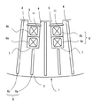
図10は従来の回転電機の電機子の主要構成を示す縦断面図、図11は図10における電機子の部分横断面図、図12は図10における電機子の抜き板鉄心の一部を示す部分斜視図、図13は図10における抜き板鉄心の端板1枚の形状を示す平面図である。 FIG. 10 is a longitudinal sectional view showing a main configuration of an armature of a conventional rotating electric machine, FIG. 11 is a partial transverse sectional view of the armature in FIG. 10, and FIG. 12 shows a part of a blank core of the armature in FIG. FIG. 13 is a partial perspective view, and FIG. 13 is a plan view showing the shape of one end plate of the punched-sheet iron core in FIG.
図10に示すように、回転電機の電機子は、図示しない回転子の軸方向に互いに間隔を保って配置される抜き板鉄心3および通風ダクト2を備えている。この抜き板鉄心3は、略扇形の珪素鋼板から成る抜き板9を、所定数量を回転電機の円周方向に環状に配置し、図示しない回転子の軸方向に所定数積層して構成される。
As shown in FIG. 10, the armature of the rotating electrical machine includes a punched-
この抜き板鉄心3にはティース(歯部)4およびスロット5が内周に沿って周方向に交互に並ぶように形成されており、略扇形に分割されている。分割される位置は、図13に示すように、スロット5もしくはスロット5とティース4の境界部とするのが一般的である。一方、通風ダクト2は抜き板鉄心3の積層方向相互間に所定の間隔をおいて、抜き板と同形状に形成された端板10に半径方向に内側間隔片6を配設して構成される。この内側間隔片6は鉄鋼材料からなり、スロット底部7から電機子鉄心1の外周方向に延びる内側間隔片6aとティース4の先端部から電機子鉄心1の外周方向に延びる内側間隔片6bとからなる。
Teeth (tooth portions) 4 and
この場合、長年の運転により電機子鉄心1の締付力が減少した場合に、回転子の磁気吸引力や鉄心の磁気振動などにより、内側間隔片6が脱落しないように、内側間隔片6bは、抜き板9と同じ珪素鋼板で構成するか、あるいは別の鉄板で構成した、抜き板9と同一形状の端板10に点溶接等によって取り付けられるのが一般的である。
In this case, when the tightening force of the
また、電機子鉄心1の抜き板鉄心3のスロット5内には、電機子巻線8が介挿されている。この電機子巻線8は楔11によって抜き板鉄心3のスロット5内に固定される。通常、電機子巻線8は下側電機子巻線8aと上側電機子巻線8bとで構成される。
An armature winding 8 is inserted in the
ところで、回転電機においては、運転中、特に、電機子鉄心1の電機子巻線8において電気抵抗に基づくジュール熱が発生する。この発熱を抑制するために、通常、回転電機の回転子側から通風ダクト2の径方向にかけて冷媒を流動させ、電機子巻線8および隣接する抜き板鉄心3に生じた熱を奪って冷却するようにしている。
By the way, in the rotating electric machine, during operation, Joule heat based on electric resistance is generated particularly in the armature winding 8 of the
このとき、冷媒は図示しない回転子に近いティース4から通風ダクト2内に流入し、電機子巻線8および隣接する抜き板9からなる抜き板鉄心3を冷却し、内側間隔片6aにより分流されて通風ダクト2の抜き板鉄心外径側に流れ、電機子鉄心1の外周方向に流出して行く。この冷媒は電機子鉄心1の外径側から回転電機外部の図示しない冷却器に導かれ、そこで熱交換されて冷却された冷媒が再び冷却のために回転電機内に戻入され循環する。
ところで、回転電機運転中の磁束の関係をみると、鉄鋼材料からなる内側間隔片6bに回転子側から入射した磁束は、内側間隔片6bに沿って抜き板鉄心3の径方向に移動しながら、抜き板鉄心3の軸方向に入射し、その後、ティース4より外径側で周方向に向きを変えて抜き板鉄心3内を通り、図示しない界磁磁極側に達する。
By the way, looking at the relationship of the magnetic flux during operation of the rotating electrical machine, the magnetic flux incident on the
ところが、この構成では内側間隔片6bを通る磁束が、電機子鉄心1の抜き板鉄心3へ移行する時に、抜き板鉄心3の積層方向と直角に入ることになり、抜き板鉄心3内に渦電流を誘導してしまい、損失(渦電流損)を発生する。特に、内側間隔片6bを取り付けている端板10には大きな渦電流が流れ、損失も大きくなる。
However, in this configuration, when the magnetic flux passing through the
さらに、この渦電流損は内側間隔片6bの磁束に対する磁気抵抗を等価的に大きくし、内側間隔片6bの磁束が減少する。
Furthermore, this eddy current loss increases the magnetic resistance of the
このように、上述した従来の構成では、抜き板鉄心3と内側間隔片6bの接合部分等で局所的な温度上昇が発生すると共に、内側間隔片6bの磁束が有効に活用できないという課題があった。
As described above, in the conventional configuration described above, there is a problem that a local temperature rise occurs at a joint portion of the punched-
そこで、特許文献1のように、内側間隔片を非磁性体の中空棒と、この中空棒内に挿入された複数本の磁性体細線により構成するとともに、内側間隔片の外周側に、電機子鉄心の反回転子側の面と磁性体細線とを磁気的に連結する磁気通路片を設けることによって、内側間隔片から鉄心への磁束移行を小さくすることが行なわれている。
Therefore, as in
しかしながら、この方法では、内側間隔片の構造が複雑となり、従来の方法に比べて製作効率が大きく低下し、かつ製造コストも増大するという課題があった。 However, this method has a problem in that the structure of the inner spacing piece is complicated, the manufacturing efficiency is greatly reduced, and the manufacturing cost is increased as compared with the conventional method.
そこで、本発明においては、簡易な構成で、内側間隔片から鉄心部への磁束の移行によって発生する渦電流損失を減少できる回転電機の電機子を提供することを目的とする。 Therefore, an object of the present invention is to provide an armature for a rotating electrical machine that can reduce eddy current loss caused by transfer of magnetic flux from an inner spacing piece to an iron core with a simple configuration.
上記の目的を達成するために、本発明に係る回転電機の電機子の一つの態様は、磁性材からなり、ティースおよびスロットが周方向に交互に配列され形成された複数個の扇形の抜き板を周方向に環状に突き合わせたものを、軸方向に所定の間隔毎に径方向の通風ダクトを形成するように積層して構成した抜き板鉄心と、この抜き板鉄心のスロットに配設された電機子巻線と、前記抜き板鉄心の通風ダクト側端面に介挿され前記抜き板に形成されたティースおよびスロットが一致するようにティースおよびスロットが形成された端板と、前記端板に形成されたティースに抜き板鉄心半径方向に延びるように設けられ、前記通風ダクトにおいて冷媒を前記抜き板鉄心の半径方向に流通させるよう形成した磁性材からなる複数個の内側間隔片と、を備えた回転電機の電機子において、前記端板のティースに抜き板鉄心半径方向に延びる間隙部を形成し、当該間隙部を跨ぐように内側間隔片を配設したことを特徴とする。 In order to achieve the above object, one aspect of the armature of a rotating electrical machine according to the present invention is made of a magnetic material, and a plurality of fan-shaped blanks formed by alternately arranging teeth and slots in the circumferential direction. Are formed in a stack in a circumferential direction so as to form radial ventilation ducts at predetermined intervals in the axial direction, and are disposed in slots of the punched plate core. Formed on the end plate, the armature winding, the end plate having teeth and slots formed so that the teeth and slots formed on the extraction plate are inserted into the end surface of the ventilation plate side of the extraction plate core. A plurality of inner spacing pieces made of magnetic material provided in the teeth so as to extend in the radial direction of the punched-sheet iron core and configured to circulate the refrigerant in the radial direction of the punched-sheet iron core in the ventilation duct. In the armature of the example it was rotating electrical machine, said end plate tooth gap portion is formed extending in the punching plate core radially of, characterized in that disposed inside distance piece so as to straddle the gap.
また、本発明に係る回転電機の電機子の他の一つの態様は、磁性材からなり、ティースおよびスロットが周方向に交互に配列され形成された複数個の扇形の抜き板を周方向に環状に突き合わせたものを、軸方向に所定の間隔毎に径方向の通風ダクトを形成するように積層して構成した抜き板鉄心と、この抜き板鉄心のスロットに配設された電機子巻線と、前記抜き板鉄心の通風ダクト側端面に介挿され前記抜き板に形成されたティースおよびスロットが一致するようにティースおよびスロットが形成された端板と、前記端板に形成されたティースに抜き板鉄心半径方向に延びるように設けられ、前記通風ダクトにおいて冷媒を前記抜き板鉄心の半径方向に流通させるよう形成した磁性材からなる複数個の内側間隔片と、を備えた回転電機の電機子において、前記端板はティースが隣接する端板の周方向突合せ部となるように形成するとともに、前記端板の突合せ部にて互いに隣接する端板同士の間に間隙部を形成するように環状に形成し、前記端板の突合せ部に形成された前記間隙部のうち少なくともティースに形成された間隙部を跨ぐように内側間隔片を配置したことを特徴とする。 Another aspect of the armature of the rotating electrical machine according to the present invention is a ring of a plurality of fan-shaped punching plates made of a magnetic material and formed by alternately arranging teeth and slots in the circumferential direction. A punched-sheet iron core that is laminated to form a radial ventilation duct at predetermined intervals in the axial direction, and an armature winding disposed in a slot of the punched-sheet core. An end plate in which teeth and slots are formed so that the teeth and slots formed in the extraction plate are inserted into the end surface of the extraction plate on the side of the ventilation duct, and the teeth formed in the end plate are extracted. A plurality of inner spacing pieces made of a magnetic material provided so as to extend in the radial direction of the sheet core and configured to circulate the refrigerant in the radial direction of the punched sheet core in the ventilation duct. In the child, the end plate is formed so that the teeth become a circumferential abutting portion of the adjacent end plates, and a gap portion is formed between the adjacent end plates at the abutting portion of the end plate. An inner spacing piece is disposed so as to straddle at least the gap portion formed in the tooth among the gap portions formed in the abutting portion of the end plate.
本発明によれば、回転電機の運転時において、内側間隔片を通過する磁束が抜き板鉄心に移行する際に端板に誘起される渦電流が、間隙部によって流路を分断されるため、渦電流損失を低減することができ、機器効率を向上させることが可能となる。 According to the present invention, during the operation of the rotating electrical machine, the eddy current induced in the end plate when the magnetic flux passing through the inner spacing piece is transferred to the punched plate core, the flow path is divided by the gap portion. Eddy current loss can be reduced, and the device efficiency can be improved.
以下、本発明に係る回転電機の電機子の第1の実施形態について、図面を参照して説明する。 Hereinafter, a first embodiment of an armature of a rotating electrical machine according to the present invention will be described with reference to the drawings.
[第1の実施形態]
本発明の第1の実施形態について図1ないし図5を参照して説明する。ここで、前述の従来技術と共通の部分には共通の符号を付して、重複説明は省略する。
[First Embodiment]
A first embodiment of the present invention will be described with reference to FIGS. Here, the same reference numerals are given to the parts common to the above-described conventional technology, and the duplicated explanation is omitted.
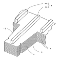
図1は本発明に係る第1の実施形態の回転電機の電機子における抜き板鉄心の一部を示す部分斜視図、図2は図1における抜き板鉄心の端板の一部を示す部分平面図、図3は図2の抜き板鉄心の端板に内側間隔片を取り付けた状態を示す図である。また、図4は第1の実施形態の回転電機の電機子の抜き板鉄心の端板のティースにおいて内側間隔片を配設した状態を示す部分断面図、図5は第1の実施形態の回転電機の電機子の抜き板鉄心の端板の周方向突合せ部において内側間隔片を接合した状態を示す部分断面図である。 FIG. 1 is a partial perspective view showing a part of a punched-sheet core in the armature of the rotary electric machine according to the first embodiment of the present invention, and FIG. 2 is a partial plan view showing a part of an end plate of the punched-sheet core in FIG. FIGS. 3A and 3B are views showing a state in which an inner spacing piece is attached to the end plate of the punched-sheet iron core of FIG. FIG. 4 is a partial cross-sectional view showing a state in which inner spacing pieces are arranged in the teeth of the end plate of the armature punched plate core of the rotating electric machine of the first embodiment, and FIG. 5 is the rotation of the first embodiment. It is a fragmentary sectional view which shows the state which joined the inner side space | interval piece in the circumferential direction butt | matching part of the end plate of the punched-plate iron core of an armature of an electric machine.
図1において、略扇形の抜き板9を円環状に突き合わせたものを軸方向に通風ダクトが形成されるように所定間隔毎に内側間隔片6を配設して積層してなる抜き板鉄心3の積層端部には抜き板9と同形状の端板10が配設されている。内側間隔片6は、ティース4から端板10の外径側およびスロット底部7から端板10の外周側にかけて、磁性材からなる内側間隔片6a、6bが端板10の径方向に放射状に設けられて構成されている。この内側間隔片6a、6bは断面矩形に形成されているが、I型鋼を用いるなど、横断面の形状は問わない。
In FIG. 1, a punched-
この内側間隔片6a、6bは端板10に点溶接等の方法で接合されている。また、端板10のティース4には、スリット(間隙部)13が形成されている。
The
図2に示すように、スリット13の長さはティース4aの長さに対して、3分の2から1の範囲の長さに形成されている。また、ティース4aに設けられる内側間隔片6は、図3に示すように、端板10のティース4bの突合せ部14を跨いで設けられる内側間隔片6b、ティース4aに設けられたスリット13を跨ぐように設けられた内側間隔片6bs、およびスロット底部7付近から端板10の外径側にかけて配設された内側間隔片6aで構成されている。
As shown in FIG. 2, the length of the
図4は第1の実施の形態に係る抜き板鉄心3のティース4a近傍の横断面図を示すものであり、端板10(10x、10y)のティース4aにスリット13を設け、内側間隔片6bsがスリット13を跨ぐように設置した状態を示している。内側間隔片6bは、例えば、端板10xに点溶接等による溶接部15で取り付けられている。端板10xに対向して設けられた端板10y側には通常は固定されることはなく、特に溶接等は施されていないが、もちろん、端板10y側に点溶接を行なっても良い。
FIG. 4 shows a cross-sectional view of the vicinity of the tooth 4a of the punched-
また、図2および図3に示すように、本実施形態においては、端板10の周方向の突合せ部14は、図13に示した従来例のようにスロット5でなく、ティース4に設けられており、内側間隔片6bはティース4に設けられた端板10x、10yの周方向の突合せ部14を跨ぐように配設されている。
As shown in FIGS. 2 and 3, in the present embodiment, the
図5は第1の実施の形態に係る端板10a、10b、10c、10dのティース4aの周方向突合せ部14近傍における内側間隔片6bと端板の接合状況を示す横断面図を示しており、突合せ部14を跨ぐように配設された内側間隔片6bは、端板10aに点溶接等による溶接部15で取り付けられている。電機子鉄心1の組立ての際は、図の右側の端板10bを先に置き、その隣に端板10aを乗せる。端板10a、10bと対向して設けられた端板10c、10d側には、特に溶接等は施されていないが、もちろん、端板10c、10dについても点溶接を行なっても良い。
FIG. 5 is a cross-sectional view showing a joining state of the
本実施の形態は上記構成からなり、回転電機の運転時、内側間隔片6b、6bsを通過する磁束が抜き板鉄心3に移行する際に端板10a、10b、10c、10dに誘起される渦電流は、スリット13によって流路を分断されて抑制されるため、渦電流損失を低減することができる。
The present embodiment is configured as described above, and the vortex induced in the end plates 10a, 10b, 10c, and 10d when the magnetic flux passing through the
図9に、450MVA級タービン発電機において3次元磁界解析によって計算した磁性材からなる内側間隔片6bsに生じる渦電流密度の径方向分布の一例を示した。 FIG. 9 shows an example of the radial distribution of eddy current density generated in the inner spacing piece 6bs made of a magnetic material calculated by three-dimensional magnetic field analysis in a 450 MVA class turbine generator.
このグラフから判るように、内側間隔片6bs内の渦電流密度はティース4先端から少し内側に入った位置で最大となり、スロット底部に近づくに従って小さくなっている。内側間隔片6bsから抜き板鉄心3に移行する磁束の量も図9の渦電流密度に応じて変るが、径方向位置の67%から100%、すなわち、ティース長さの3分の2から1の範囲では、渦電流密度はピーク値の半分以下になっている。端板10に設けるスリット13の長さは短い方が鉄心の剛性を強くでき、製造コストを抑えることもできるため、渦電流の抑制を効果的に行なうことを考え合わせると、スリットの長さをティース長さの3分の2から1の範囲にすることで、効果的に端板10で発生する渦電流損失を抑制することができるといえる。
As can be seen from this graph, the eddy current density in the inner spacing piece 6bs becomes maximum at a position slightly inside from the tip of the
また、端板10の周方向の突合せ部14がティース4bにあって、内側間隔片6bがこの突合せ部を跨ぐように設置されているため、内側間隔片6bに入った磁束が抜き板鉄心3に移行する際に端板10に誘起される渦電流は、端板10の周方向の突合せ部14によって流路を分断されることで抑制されるため、渦電流損失を低減することができる。
Further, since the
本実施の形態によれば、内側間隔片6b、6bsから磁束が抜き板鉄心3に移行する際に端板10に誘起される渦電流損失が増大するのを抑えることができ、機器効率をより向上させることが可能になる。
According to the present embodiment, it is possible to suppress an increase in eddy current loss induced in the
[第2の実施形態]
つぎに、本発明の第2の実施形態について図6を参照して説明する。
[Second Embodiment]
Next, a second embodiment of the present invention will be described with reference to FIG.
図6は第2の実施形態に係る回転電機の電機子の抜き板鉄心の端板に内側間隔片を配設した状態を示す部分構成を示す図である。第1の実施形態と同様の構成については同一の符号を付して説明を省略する。なお、図6においては、内側間隔片6a、6b、6bsを破線で示す。
FIG. 6 is a diagram showing a partial configuration showing a state in which inner spacing pieces are arranged on the end plate of the punched-plate core of the armature of the rotating electrical machine according to the second embodiment. The same components as those in the first embodiment are denoted by the same reference numerals and description thereof is omitted. In FIG. 6, the
図6において、端板10の突合せ部14はティース4bの内径側から外径側に延びている。ティース4bより端板10の外径側において、スロット底部7とほぼ同一の周方向位置に相当する突合せ部14aの位置から、ティース4bにおける突合せ部14bに対して周方向に傾きを設けてティース4bの端板外径側に突合せ部14cが形成されており、端板10外径側においては内側間隔片6bと突合せ部14cとがずれた構造になっている。
In FIG. 6, the butting
このような構造であるので、内側間隔片6bは端板10の外径側で端板10との接触面積が大きくなる。そのため、電機子鉄心1の締付力が増加し、回転電機の信頼性をより高めることができる。
Due to such a structure, the
なお、突合せ部14cの端板10の外径側での傾き角度は、ティース4bにおける突合せ部14bに対して0.5度以上ずれていれば、ティース4bより外径側にある内側間隔片6bの約半分の長さが、突合せ部14cに接することなく、端板10を押えることができる。
In addition, if the inclination angle on the outer diameter side of the
[第3の実施形態]
つぎに、本発明の第3の実施形態について図面を参照して説明する。
[Third Embodiment]
Next, a third embodiment of the present invention will be described with reference to the drawings.
図7は本発明の第3の実施形態の回転電機の電機子の抜き板鉄心の端板に内側間隔片を配設した状態を示す部分構成図である。第1、第2の実施形態と同様の構成については同一の符号を付して説明を省略する。なお、図7においては、内側間隔片6a、6b、6c、6dを破線で示す。
FIG. 7 is a partial configuration diagram showing a state in which inner spacing pieces are arranged on the end plate of the punched-plate core of the armature of the rotating electric machine according to the third embodiment of the present invention. The same components as those in the first and second embodiments are denoted by the same reference numerals and description thereof is omitted. In FIG. 7, the
図7において、端板10の突合せ部14はティース4bの先端部から端板10の外径側端部にかけて直線状に形成されており、内側間隔片6cはティース4bの内径側端部から外径側に沿ってティース4bの根元部付近までは突合せ部14の隙間を跨ぐように設けられ、ティース4の根元部よりも外径側で、周方向に傾きを変えて形成され、端板10の外径側では内側間隔片6cと突合せ部14がずれた構造になっている。
In FIG. 7, the abutting
このような構造であるので、内側間隔片6cは端板10の外径側では端板10との接触面積が大きくなるため、電機子鉄心1の締付力が増加し、回転電機を信頼性をより高めることができる。
With such a structure, the inner spacing piece 6c has a larger contact area with the
なお、内側間隔片6cの端板10外径側における突合せ部14に対する傾き角度に関しては、概ね0.5度以上あれば、ティース4bより外径側にある内側間隔片6cの約半分の長さが、突合せ部14に接することなく、端板10を押えることができ、良好に電機子鉄心の締付力を確保することができる。
The inclination angle of the inner spacing piece 6c with respect to the abutting
また、図7では、突合せ部14に接していない内側間隔片6aや6dも、外径側で、径方向から周方向に傾きを変えているが、これは内側間隔片6cに合せて、通風ダクトの流路を確保するために行なっているものである。こうすることによって、回転電機の電機子鉄心の通風ダクトを流れる冷媒の量を良好に確保することができ、電機子巻線や電機子鉄心の温度を良好に保つことができる。
In FIG. 7, the
[第4の実施形態]
つぎに、本発明の第4の実施形態について図面を参照して説明する。
[Fourth Embodiment]
Next, a fourth embodiment of the present invention will be described with reference to the drawings.
図8は本発明の第4の実施形態に係る回転電機の電機子の端板の周方向突合せ部近傍における内側間隔片と端板の接合状況を示す横断面図を示している。第1乃至第3の実施形態と同様の構成については同一の符号を付して説明を省略する。 FIG. 8: has shown the cross-sectional view which shows the joining condition of the inside space | interval piece and end plate in the circumferential direction butt | matching part vicinity of the end plate of the armature of the rotary electric machine which concerns on the 4th Embodiment of this invention. The same components as those in the first to third embodiments are denoted by the same reference numerals and description thereof is omitted.
図8において、端板10に設けたスリット13には、樹脂から成る充填材16が注入されており、内側間隔片6からの圧力を受ける抜き板鉄心3の面積を増加するとともに、スリット13の両側の端板10が別々に振動することを抑制している。
In FIG. 8, a
このような構成であるので、スリット13を設けることによって鉄心の締付力が減少するのを抑えることができ、また長年の運転によってスリット13の両側の端板10が振動することで鉄心の締付が低下するのを抑制できる。
Due to such a configuration, it is possible to suppress the reduction of the tightening force of the iron core by providing the
なお、本実施形態では、充填材16をスリット13に注入したものについて述べたが、端板10の周方向突合せ部に形成される隙間に、充填材16を注入してもよい。
In the present embodiment, the
また、充填材16としては、樹脂中に磁性体、例えば、圧粉磁性体のように磁気特性を有し、かつ充填材内での渦電流の発生が抑制できるような電気抵抗が高いものが好ましい。これにより、主磁束に対する抜き板鉄心3の磁気抵抗がスリット13によって減少することが抑えられるため、回転子側の界磁電流の増加を防ぎ、界磁銅損の発生を抑制し、より高効率な回転電機を提供することが可能となる。なお、磁気特性を有する充填材を充填する場合には、端板10のスリット13表面には絶縁処理を施して絶縁皮膜を形成しておくことで、充填材16により電気的な導通が生じることを抑制できる。
Further, the
以上のように、スリット13の隙間を充填材16で充填したことにより、スリット13部において鉄心の締付力が減少するのを抑えることができ、回転子側の界磁電流の増加を防ぎ、界磁銅損の発生を抑制し、より高効率な回転電機を提供することができる。
As described above, by filling the gap of the
なお、充填材16はスリット13部だけでなく、端板10の突合せ部14に生じる隙間にも磁性充填材16を注入することでより効果が期待できる。
The
1 : 電機子鉄心
2 : 通風ダクト
3 : 抜き板鉄心
4、4a、4b : ティース
5、5a : スロット
6、6a、6b、6bs、6c、6d : 内側間隔片
7 : スロット底部
8 : 電機子巻線
9 : 抜き板
10、10x、10y、10a、10b、10c、10d : 端板
11 : 楔
12 : 絶縁層
13 : スリット(間隙部)
14 : 突合せ部
15 : 溶接部
16 : 充填材
1: Armature core 2: Ventilation duct 3: Die
14: Butt part 15: Welded part 16: Filler
Claims (8)
この抜き板鉄心のスロットに配設された電機子巻線と、
前記抜き板鉄心の通風ダクト側端面に介挿され前記抜き板に形成されたティースおよびスロットが一致するようにティースおよびスロットが形成された端板と、
前記端板に形成されたティースに抜き板鉄心半径方向に延びるように設けられ、前記通風ダクトにおいて冷媒を前記抜き板鉄心の半径方向に流通させるよう形成した磁性材からなる複数個の内側間隔片と、
を備えた回転電機の電機子において、
前記端板のティースに抜き板鉄心半径方向に延びる間隙部を形成し、当該間隙部を跨ぐように内側間隔片を配設したことを特徴とする回転電機の電機子。 A ventilation duct that is made of a magnetic material and has a plurality of fan-shaped punching plates formed by alternately arranging teeth and slots in the circumferential direction and annularly butted in the circumferential direction at a predetermined interval in the axial direction. A punched iron core that is laminated and formed to form
An armature winding disposed in the slot of the punched iron core;
An end plate having teeth and slots formed so that the teeth and slots formed in the punch plate are inserted in the end surface of the punch plate core on the side of the ventilation duct;
A plurality of inner spacing pieces made of a magnetic material provided on the teeth formed on the end plate so as to extend in the radial direction of the punched-sheet core and configured to circulate refrigerant in the radial direction of the punched-sheet core in the ventilation duct When,
In the armature of a rotating electric machine with
An armature for a rotating electric machine, wherein a gap portion extending in a radial direction of a punched-sheet iron core is formed in a tooth of the end plate, and an inner spacing piece is disposed so as to straddle the gap portion.
この抜き板鉄心のスロットに配設された電機子巻線と、
前記抜き板鉄心の通風ダクト側端面に介挿され前記抜き板に形成されたティースおよびスロットが一致するようにティースおよびスロットが形成された端板と、
前記端板に形成されたティースに抜き板鉄心半径方向に延びるように設けられ、前記通風ダクトにおいて冷媒を前記抜き板鉄心の半径方向に流通させるよう形成した磁性材からなる複数個の内側間隔片と、
を備えた回転電機の電機子において、
前記端板はティースが隣接する端板の周方向突合せ部となるように形成するとともに、前記端板の突合せ部にて互いに隣接する端板同士の間に間隙部を形成するように環状に形成し、前記端板の突合せ部に形成された前記間隙部のうち少なくともティースに形成された間隙部を跨ぐように内側間隔片を配置したことを特徴とする回転電機の電機子。 A ventilation duct that is made of a magnetic material and has a plurality of fan-shaped punching plates formed by alternately arranging teeth and slots in the circumferential direction and annularly butted in the circumferential direction at a predetermined interval in the axial direction. A punched iron core that is laminated and formed to form
An armature winding disposed in the slot of the punched iron core;
An end plate having teeth and slots formed so that the teeth and slots formed in the punch plate are inserted in the end surface of the punch plate core on the side of the ventilation duct;
A plurality of inner spacing pieces made of a magnetic material provided on the teeth formed on the end plate so as to extend in the radial direction of the punched-sheet core and configured to circulate refrigerant in the radial direction of the punched-sheet core in the ventilation duct When,
In the armature of a rotating electric machine with
The end plate is formed so that the teeth become a circumferential butting portion of adjacent end plates, and is formed in an annular shape so that a gap portion is formed between the adjacent end plates at the butting portion of the end plate. An inner armature piece is disposed so as to straddle at least the gap portion formed in the tooth among the gap portions formed in the butted portion of the end plate.
Priority Applications (1)
| Application Number | Priority Date | Filing Date | Title |
|---|---|---|---|
| JP2008207134A JP5058097B2 (en) | 2008-08-11 | 2008-08-11 | Rotating machine armature |
Applications Claiming Priority (1)
| Application Number | Priority Date | Filing Date | Title |
|---|---|---|---|
| JP2008207134A JP5058097B2 (en) | 2008-08-11 | 2008-08-11 | Rotating machine armature |
Publications (2)
| Publication Number | Publication Date |
|---|---|
| JP2010045897A JP2010045897A (en) | 2010-02-25 |
| JP5058097B2 true JP5058097B2 (en) | 2012-10-24 |
Family
ID=42016786
Family Applications (1)
| Application Number | Title | Priority Date | Filing Date |
|---|---|---|---|
| JP2008207134A Expired - Fee Related JP5058097B2 (en) | 2008-08-11 | 2008-08-11 | Rotating machine armature |
Country Status (1)
| Country | Link |
|---|---|
| JP (1) | JP5058097B2 (en) |
Cited By (1)
| Publication number | Priority date | Publication date | Assignee | Title |
|---|---|---|---|---|
| EP3514920A1 (en) | 2018-01-17 | 2019-07-24 | ABB Schweiz AG | A stator core or a rotor core for an electrical machine with reduced eddy current losses and high magnetic conductivity and mechanical strength |
Families Citing this family (2)
| Publication number | Priority date | Publication date | Assignee | Title |
|---|---|---|---|---|
| JP5253355B2 (en) * | 2009-10-29 | 2013-07-31 | 三菱電機株式会社 | Rotating electric machine, generator, electric motor |
| JP6910413B2 (en) * | 2019-11-07 | 2021-07-28 | 三菱電機株式会社 | Rotating machine |
Family Cites Families (3)
| Publication number | Priority date | Publication date | Assignee | Title |
|---|---|---|---|---|
| US3714477A (en) * | 1971-08-23 | 1973-01-30 | Gen Electric | Combination flux shield and flux shunt for a dynamoelectric machine |
| JP2001178034A (en) * | 1999-12-21 | 2001-06-29 | Toshiba Corp | Armature core of dynamoelectric machine |
| JP4095347B2 (en) * | 2002-05-29 | 2008-06-04 | 株式会社東芝 | Rotating electric machine stator |
-
2008
- 2008-08-11 JP JP2008207134A patent/JP5058097B2/en not_active Expired - Fee Related
Cited By (3)
| Publication number | Priority date | Publication date | Assignee | Title |
|---|---|---|---|---|
| EP3514920A1 (en) | 2018-01-17 | 2019-07-24 | ABB Schweiz AG | A stator core or a rotor core for an electrical machine with reduced eddy current losses and high magnetic conductivity and mechanical strength |
| WO2019141400A1 (en) | 2018-01-17 | 2019-07-25 | Abb Schweiz Ag | A stator core or a rotor core for an electrical machine with reduced eddy current losses and high magnetic conductivity and mechanical strength |
| US10992192B2 (en) | 2018-01-17 | 2021-04-27 | Abb Schweiz Ag | Stator core or a rotor core for an electrical machine with reduced eddy current losses and high magnetic conductivity and mechanical strength |
Also Published As
| Publication number | Publication date |
|---|---|
| JP2010045897A (en) | 2010-02-25 |
Similar Documents
| Publication | Publication Date | Title |
|---|---|---|
| JP5379550B2 (en) | Armature | |
| US8624462B2 (en) | Rotating electrical machine | |
| US7893575B2 (en) | Rotor with field coils in optimized flux space slots | |
| JP5736861B2 (en) | Rotating electrical machine rotor | |
| JP6328263B2 (en) | Armature laminated core and armature | |
| JP5641341B2 (en) | Armature | |
| WO2016080284A1 (en) | Induction motor | |
| EP1633031A2 (en) | Electrical rotating machine | |
| JP2011078294A (en) | Armature core | |
| JP2014187862A (en) | Manufacturing method of rotor lamination iron core | |
| JP5058097B2 (en) | Rotating machine armature | |
| JP5690078B2 (en) | Rotating electromechanical rotor with enhanced heat transfer and method therefor | |
| JP5840071B2 (en) | Method for manufacturing laminated core of electric motor | |
| JP5253355B2 (en) | Rotating electric machine, generator, electric motor | |
| JP2016036193A (en) | Induction motor | |
| JP2013172568A (en) | Rotary electric machine | |
| KR20200015903A (en) | Inserts for Carriers for Electrical Machines | |
| JP2016082627A (en) | Stator for rotary electric machine | |
| JP2009095189A (en) | Split stator and motor | |
| JP6067785B2 (en) | Laminated iron core and method for manufacturing the same | |
| JP5601534B2 (en) | Armature | |
| JP5720891B2 (en) | Stator and manufacturing method thereof | |
| JP2011078233A (en) | Armature core | |
| JP2020150678A (en) | Rotary electric machine stator | |
| JP2012075271A (en) | Armature core and rotary electric machine equipped with the same |
Legal Events
| Date | Code | Title | Description |
|---|---|---|---|
| A621 | Written request for application examination |
Free format text: JAPANESE INTERMEDIATE CODE: A621 Effective date: 20101020 |
|
| RD04 | Notification of resignation of power of attorney |
Free format text: JAPANESE INTERMEDIATE CODE: A7424 Effective date: 20110420 |
|
| TRDD | Decision of grant or rejection written | ||
| A01 | Written decision to grant a patent or to grant a registration (utility model) |
Free format text: JAPANESE INTERMEDIATE CODE: A01 Effective date: 20120703 |
|
| A01 | Written decision to grant a patent or to grant a registration (utility model) |
Free format text: JAPANESE INTERMEDIATE CODE: A01 |
|
| A977 | Report on retrieval |
Free format text: JAPANESE INTERMEDIATE CODE: A971007 Effective date: 20120704 |
|
| A61 | First payment of annual fees (during grant procedure) |
Free format text: JAPANESE INTERMEDIATE CODE: A61 Effective date: 20120731 |
|
| FPAY | Renewal fee payment (event date is renewal date of database) |
Free format text: PAYMENT UNTIL: 20150810 Year of fee payment: 3 |
|
| FPAY | Renewal fee payment (event date is renewal date of database) |
Free format text: PAYMENT UNTIL: 20150810 Year of fee payment: 3 |
|
| LAPS | Cancellation because of no payment of annual fees |