JP5055213B2 - Mounting structure and mounting method of exterior panel and trunk edge - Google Patents
Mounting structure and mounting method of exterior panel and trunk edge Download PDFInfo
- Publication number
- JP5055213B2 JP5055213B2 JP2008183306A JP2008183306A JP5055213B2 JP 5055213 B2 JP5055213 B2 JP 5055213B2 JP 2008183306 A JP2008183306 A JP 2008183306A JP 2008183306 A JP2008183306 A JP 2008183306A JP 5055213 B2 JP5055213 B2 JP 5055213B2
- Authority
- JP
- Japan
- Prior art keywords
- exterior panel
- trunk edge
- exterior
- top surface
- fixed
- Prior art date
- Legal status (The legal status is an assumption and is not a legal conclusion. Google has not performed a legal analysis and makes no representation as to the accuracy of the status listed.)
- Expired - Fee Related
Links
Images


Landscapes
- Finishing Walls (AREA)
Description
本発明は、外装パネルと胴縁の取付構造及び取付方法に関し、特に、外装パネルと胴縁を容易に取付けることができる技術に関する。 The present invention relates to a mounting structure and a mounting method for an exterior panel and a trunk edge, and more particularly to a technique capable of easily mounting the exterior panel and the trunk edge.
従来、建築物の外壁本体に取付けるための外装パネルと胴縁の取付構造及び取付方法として特許文献1の内容が知られている。図5に示すように、特許文献1の外装パネル1は係合部材10と保持部材11を介して胴縁26に固着される。係合部材10は鋼鈑を折り曲げて連続的に形成され、その断面形状は両側の第1側壁部12と第2側壁部13が概略平行で、第1側壁部12と第2側壁部13の先端を折返して凸部18、19を形成し、折返した第1側壁部12と第2側壁部13の間に底壁部14が形成される。
Conventionally, the contents of
外装パネル1は下端部に雌型嵌合部5と上端部に雄型嵌合部6が形成され、雌型嵌合部5に係合部材10の凸部18と雄型嵌合部6が嵌合される。凸部19の高さは外装パネル1の固定部7より高く形成されており、凸部18を雌型嵌合部5に嵌合させた状態で固定部7を収容できるようになっている。そして、保持部材11が釘27を用いて胴縁26に固着され、この保持部材11に係合部材10が差し込まれて固着する。
The
ところが、保持部材11を胴縁26に固着する際に使用する各外装パネル1毎に使用する釘27の数が多いので作業に手間取り作業効率が悪いという問題があった。この問題を解決する方法として、図6に示すように保持部材11が用いられない構成が知られている。図6の胴縁26aと外装パネル1aの取付けは、最初に胴縁26aが外装パネル1aの上下方向のピッチに合わせて各一本の釘28を使用して外壁本体に固定され、その後、外装パネル1aの固定部7aを胴縁26aに一本の釘28aで固定する。同様に上方の外装パネル1aの凹部1bを下方の外装パネル1aの凸部1cに嵌合させた状態で上方の外装パネル1aの図示しない固定部を一本の釘28aで胴縁26aに固定する。このように上方に向けて順次各外装パネル1a毎に2本の釘28、28aを使用して、各外装パネル1aを胴縁26aを介して建築物の外壁本体に取付けることができる。
ところが、外壁本体に予め胴縁26aを釘28で固定した後に外装パネル1aを組みつけるので、胴縁26aと外装パネル1aの取付工程が異なるため作業効率が悪いという問題があった。
However, since the exterior panel 1a is assembled after the
そこで、本発明は、外壁本体に胴縁と外装パネルを同じ工程で安定して取付けることのできる外装パネルと胴縁の取付構造及び取付方法を提供することを目的とする。 Therefore, an object of the present invention is to provide a mounting structure and mounting method for an exterior panel and a trunk edge that can stably mount the trunk edge and the exterior panel to the outer wall main body in the same process.
請求項1の発明は、建築物の外壁本体に横張りで取付けられる複数の外装パネルと胴縁の取付構造であって、前記外装パネルは断面略矩形状で上端面に凸部を備えるとともに外装パネルの裏面を延長して前記凸部より突出する固定部を形成し、前記外装パネルの下端部に凹部を備えるとともに前記裏面を抉って隣接する外装パネルの前記固定部を覆う抉り部を形成し、前記胴縁は頂面と二側面からなる断面コ字状の長尺材で前記外装パネル毎に複数組備え、前記固定部と前記胴縁を位置合わせすると同時に釘等の固定具を介して外壁本体に固定するため前記胴縁の頂面の上端部に前記外装パネルの固定部と係止する係止部が形成され、前記係止部は前記胴縁の頂面を折込んで水平部と垂直部で形成されることを特徴としている。
The invention according to
請求項2の発明は、請求項1に記載の外装パネルと胴縁の取付構造であって、前記胴縁の両側面に通気孔が形成されることを特徴としている。 According to a second aspect of the present invention, there is provided a structure for mounting the exterior panel and the trunk edge according to the first aspect, wherein vent holes are formed on both side surfaces of the trunk edge.
請求項3の発明は、建築物の外壁本体に横張りで取付けられる複数の外装パネルと胴縁の胴縁の取付方法であって、前記外装パネルは断面略矩形状で上端面に凸部を備えるとともに外装パネルの裏面を延長して前記凸部より突出する固定部を形成し、前記外装パネルの下端面に凹部を備えるとともに前記裏面を抉って隣接する外装パネルの前記固定部を覆う抉り部を形成し、前記胴縁は頂面と二側面からなる断面コ字状の長尺材で前記外装パネル毎に形成され、前記胴縁の頂面の上端部に前記外装パネルの固定部と係止する係止部が形成され、前記係止部は前記胴縁の頂面を折込んで水平部と垂直部で形成され、前記外装パネルを外壁本体に取付ける際に、前記外装パネルの固定部に前記係止部を介して前記胴縁を係止した状態で隣接する前記胴縁の上下端部が当接する位置まで移動させて、釘等の固定具で前記固定部と前記胴縁の頂面を一体的に外壁本体に固定することを特徴としている。 The invention of claim 3 is a method of attaching a plurality of exterior panels and a trunk edge of a trunk edge that are laterally attached to an outer wall body of a building, wherein the exterior panel is substantially rectangular in cross section and has a convex portion on the upper end surface. And forming a fixed portion that extends from the convex portion by extending the back surface of the exterior panel, and includes a recess at the lower end surface of the exterior panel and covers the fixed portion of the adjacent exterior panel across the back surface. The body edge is formed of a long material having a U-shaped cross section consisting of a top surface and two side surfaces for each of the exterior panels, and the upper end portion of the top surface of the body edge is engaged with a fixing portion of the exterior panel. A locking portion for stopping is formed, and the locking portion is formed of a horizontal portion and a vertical portion by folding the top surface of the trunk edge, and when the exterior panel is attached to the outer wall main body, Before adjoining in the state where the trunk edge is locked via the locking portion Upper and lower end portions of the furring strip is moved to a position abutting, it is characterized by securing the integrally outer wall body of the top surface of the said fixed part in a fixture such as a nail furring strips.
請求項1の発明によれば、前記胴縁は頂面と二側面からなる断面コ字状の長尺材で前記外装パネル毎に複数組備え、前記胴縁の頂面の上端部に前記外装パネルの固定部と係止する係止部が形成されるので、前記固定部を前記胴縁に確実且つ容易に位置合わせできる。そして、頂面と前記固定部を同時に釘等の固定具を介して打ち付けることで前記外装パネルは前記胴縁と同時に一体的に外壁本体に固定することができる。このため、前記外装パネルと前記胴縁の取付が同じ工程内でできるので作業工程が短縮し作業効率が向上する。釘等の固定具の使用数減少によりコスト減になる。
According to the invention of
請求項1の発明によれば、前記係止部は前記胴縁の頂面を折込んで水平部と垂直部で形成されるので、前記係止部用に別材料を用意する必要がなく板金加工によってコスト削減できる。 According to the first aspect of the present invention, since the locking portion is formed of a horizontal portion and a vertical portion by folding the top surface of the trunk edge, it is not necessary to prepare a separate material for the locking portion, and sheet metal processing Can reduce costs.
請求項2の発明によれば、前記胴縁の両側面に通気孔が形成されるので、建築物の外壁本体と前記外装パネルとの間に自然換気ができるため通気効果が向上するので、湿気が防止できて前記外装パネルの長期品質安定が確保できる。 According to the second aspect of the present invention, the ventilation holes are formed on both side surfaces of the trunk edge, so that the ventilation effect is improved since natural ventilation can be performed between the outer wall body of the building and the exterior panel. And the long-term quality stability of the exterior panel can be ensured.
請求項3の発明によれば、前記胴縁の頂面の上端部に前記外装パネルの固定部と係止する係止部が形成され、前記係止部は前記胴縁の頂面を折込んで水平部と垂直部で形成され、前記外装パネルを外壁本体に取付ける際に、前記外装パネルの固定部に前記係止部を介して前記胴縁を係止した状態で隣接する前記胴縁の上下端部が当接する位置まで移動させて、釘等の固定具で前記固定部と前記胴縁の頂面を一体的に外壁本体に固定することができるので、前記外装パネルと前記胴縁の取付が同じ工程内でできるので作業工程が短縮し作業効率が向上する。釘等の固定具の使用数減少によりコスト減になる。 According to a third aspect of the present invention, a locking portion for locking with the fixed portion of the exterior panel is formed at the upper end portion of the top surface of the trunk edge, and the locking portion folds the top surface of the trunk edge. formed by the horizontal portion and a vertical portion, wherein the outer panel when mounting the outer wall body, and below the furring strip adjacent to each other in a state of locking the said furring strip through the locking portion to the fixed portion of the outer panel Since the end portion is moved to a position where the end abuts, and the fixing portion and the top surface of the trunk edge can be integrally fixed to the outer wall main body with a fixing tool such as a nail, the attachment of the exterior panel and the trunk edge Can be done within the same process, shortening the work process and improving work efficiency. Costs are reduced by reducing the number of fixtures such as nails.
<外装パネルと胴縁の取付構造の構成>
以下に、本発明の実施形態を図1〜図4に基づいて説明する。図1、図2、図3に示すように、本発明の複数の外装パネル31と胴縁40は建築物33の外壁本体34に横張りで上方に向けて矢印Kに示すように順番に取付けられる。
<Configuration of exterior panel and body edge mounting structure>
Embodiments of the present invention will be described below with reference to FIGS. As shown in FIGS. 1, 2, and 3, the plurality of
外装パネル31は内部の断熱材32を外側から薄肉の鋼板32aで被覆してなる金属サイディングが用いられ、外装パネル31は断面略矩形状で上端面31aの略中央部に雄実としての凸部35と外装パネル31の裏面31bを延長して凸部35より突出する固定部36が形成される。固定部36の先端36aにおいて鋼板32aは折重ねられる。外装パネル31は長さL、高さE、厚みDで形成される。凸部35は高さE1、幅D1、固定部36は幅D2で、それぞれ外装パネル31の水平方向の長さLに沿って全域に形成される。
The
外装パネル31の下端面31cの略中央部に雌実としての凹部37と裏面31bを抉って隣接する外装パネル31の固定部36を覆う抉り部38が形成される。凹部37は深さE2、幅D2で、抉り部38は高さE3、深さD3で、それぞれ外装パネル31の水平方向の長さLに沿って全域に形成される。
In the substantially central portion of the
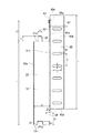
胴縁40は頂面40a(幅M)と両側面40b(高さN)からなる断面コ字状の長尺鋼板材で一枚の外装パネル31毎に数組垂直に取付けられるので、胴縁40の高さHは外装パネル31の上端面31aから下端面31cまでの高さBに等しく形成される。数組の胴縁40は水平方向に略303mm毎に配置され、胴縁40の両側面40bに通気孔41が長さS、幅T、ピッチPで数組形成され、側面40bの外壁本体34側の先端部にはフランジ40eを備える。
The
外装パネル31の固定部36と係止する係止部45は突出代T2の水平部45aと高さT3の垂直部45bで形成され、胴縁40の頂面40aにおける上端部40cの中央部に頂面40aを幅S1、高さT1で切断して折込み形成される。このため、T1=T2+T3の関係である。
The
図4に示すように、外装パネル31を外壁本体34に取付ける際に、外装パネル31の固定部36に係止部45を介して数組の胴縁40を吊り下げて係止した状態の外装パネル31を一体的に移動して、凹部37を凸部35に嵌入して重ねる。そして、釘等の固定具47によって固定部36と胴縁40の頂面40aを同時に外壁本体34に固定される。固定具47は垂直方向に胴縁40の高さHと同じ間隔で使用される。より詳しくは、図4は、既に重ねられた下方側の外装パネル31が釘等の固定具47によって固定部36と頂面40aを同時に外壁本体34に固定した状態で、さらに上方から胴縁40を吊り下げた状態の外装パネル31が重ねられた状態を示している。
As shown in FIG. 4, when the
なお、最上段の外装パネル31の上端面31aと胴縁40の上端部40c、及び最下段の外装パネル31の下端面31cと胴縁40の下端部40dは、それぞれ図示しないスターターや見切り縁等を用いて外壁本体34或いは躯体に適切に取付けられる。
<外装パネルと胴縁の取付構造の作用>
The
<Operation of mounting structure of exterior panel and trunk edge>
上記、外装パネル31を外壁本体34に取付ける際に、外装パネル31の固定部36に係止部45を介して数組の胴縁40を吊り下げて係止した状態で外装パネル31を一体的に矢印Kに示すように移動させる。そして、凹部37を下方の外装パネル31の凸部35に嵌合した状態で釘等の固定具47で固定部36と胴縁40の頂面40aを同時に一体的に外壁本体34に固定できる。このため、外装パネル31と胴縁40は一体的に同時に外壁本体34に固定するので、取付工程が同じなので作業工程が短縮できて作業効率が向上する。
When the
また、同時に釘等の固定具47の使用数が略半減するので作業効率の向上とともにコスト削減できる。なお、各胴縁40は一本の固定具47によって固定されるが、上方の胴縁40の下端部40dが下方の胴縁40の上端部40cに当接するので上方と下方の胴縁40はガタなく安定して固定される。
At the same time, since the number of
以上、本発明の実施例を図面に基づいて説明したが、具体的な構成はこの実施例に限られるものではなく本発明の要旨を逸脱しない範囲の設計変更等があっても本発明に含まれる。 The embodiment of the present invention has been described with reference to the drawings. However, the specific configuration is not limited to this embodiment, and design changes and the like within the scope of the present invention are included in the present invention. It is.
例えば、現場の作業状況によれば、外装パネル31と胴縁40を係合して移動しないで、外壁本体34で待ち受けている胴縁40に外装パネル31を係合することもできる。胴縁40の下端部40dを下方の胴縁40の上端部40cと確実に係合させるために、胴縁40のどちらか一方の端部にスリーブを内嵌して備え、このスリーブによって隣接する胴縁40の他方の端部と嵌合装着することもできる。胴縁40は断面コ字状の長尺鋼板材の代わりに木質材を用いることもできる。
For example, according to the work situation in the field, the
31 外装パネル
31a 上端面
31b 裏面
31c 下端面
33 建築物
34 外壁本体
35 凸部
36 固定部
37 凹部
40 胴縁
40a 頂面
40b 側面
40c 上端部
45 係止部
45a 水平部
45b 垂直部
31
Claims (3)
前記外装パネルを外壁本体に取付ける際に、前記外装パネルの固定部に前記係止部を介して前記胴縁を係止した状態で移動させて前記凹部を下方の前記胴縁の前記凸部に嵌合して、釘等の固定具で前記固定部と前記胴縁の頂面を一体的に外壁本体に固定することを特徴とする外装パネルと胴縁の取付方法。 A method of attaching a plurality of exterior panels and body edges that are laterally attached to an outer wall body of a building, wherein the exterior panel is substantially rectangular in cross section and has a convex portion on an upper end surface, and extends the back surface of the exterior panel. A fixed portion protruding from the convex portion is formed, a concave portion is provided at a lower end portion of the exterior panel, and a flange portion is formed to cover the fixed portion of the adjacent exterior panel over the back surface, and the trunk edge is a top surface A plurality of sets of long materials having a U-shaped cross section consisting of two side surfaces are formed for each of the exterior panels, and a locking portion for locking with a fixing portion of the exterior panel is formed at the upper end portion of the top surface of the trunk edge. The locking portion is formed of a horizontal portion and a vertical portion by folding the top surface of the trunk edge,
When the exterior panel is attached to the outer wall main body, it is moved to the fixed portion of the exterior panel in a state where the trunk edge is locked via the locking portion, and the concave portion is moved to the convex portion of the lower barrel edge. A method for attaching an exterior panel and a trunk edge, wherein the fixing portion and the top surface of the trunk edge are integrally fixed to an outer wall body by fitting with a fixing tool such as a nail.
Priority Applications (1)
| Application Number | Priority Date | Filing Date | Title |
|---|---|---|---|
| JP2008183306A JP5055213B2 (en) | 2008-07-15 | 2008-07-15 | Mounting structure and mounting method of exterior panel and trunk edge |
Applications Claiming Priority (1)
| Application Number | Priority Date | Filing Date | Title |
|---|---|---|---|
| JP2008183306A JP5055213B2 (en) | 2008-07-15 | 2008-07-15 | Mounting structure and mounting method of exterior panel and trunk edge |
Publications (2)
| Publication Number | Publication Date |
|---|---|
| JP2010024614A JP2010024614A (en) | 2010-02-04 |
| JP5055213B2 true JP5055213B2 (en) | 2012-10-24 |
Family
ID=41730695
Family Applications (1)
| Application Number | Title | Priority Date | Filing Date |
|---|---|---|---|
| JP2008183306A Expired - Fee Related JP5055213B2 (en) | 2008-07-15 | 2008-07-15 | Mounting structure and mounting method of exterior panel and trunk edge |
Country Status (1)
| Country | Link |
|---|---|
| JP (1) | JP5055213B2 (en) |
Families Citing this family (1)
| Publication number | Priority date | Publication date | Assignee | Title |
|---|---|---|---|---|
| JP6319898B2 (en) * | 2014-06-14 | 2018-05-09 | 旭トステム外装株式会社 | Metal siding metal fitting, metal siding fixing structure, and metal siding fixing method |
Family Cites Families (3)
| Publication number | Priority date | Publication date | Assignee | Title |
|---|---|---|---|---|
| JP3679479B2 (en) * | 1995-11-20 | 2005-08-03 | 住友林業株式会社 | Exterior material mounting structure |
| JPH11131748A (en) * | 1997-10-30 | 1999-05-18 | Inax Corp | Execution structure of tiled lined siding panel |
| JP4239984B2 (en) * | 2005-01-26 | 2009-03-18 | パナソニック電工株式会社 | Structure of base metal fittings for exterior panels |
-
2008
- 2008-07-15 JP JP2008183306A patent/JP5055213B2/en not_active Expired - Fee Related
Also Published As
| Publication number | Publication date |
|---|---|
| JP2010024614A (en) | 2010-02-04 |
Similar Documents
| Publication | Publication Date | Title |
|---|---|---|
| US8863461B2 (en) | Siding panel system | |
| JP5055213B2 (en) | Mounting structure and mounting method of exterior panel and trunk edge | |
| JP6957173B2 (en) | Fixtures, sets of fixtures and waterproof materials, wall structures, and construction methods for exterior materials | |
| JP2018066151A (en) | End surface mounting tool for plate material, wall structure and construction method of plate material | |
| JP2009161956A (en) | Joint structure of exterior wall external angle part | |
| JP2012067563A (en) | External wall corner part settling member and external wall corner part settling structure | |
| JP2006207201A (en) | Structure of substrate fitting for cladding panel | |
| JP4741985B2 (en) | Close edge | |
| JP5052395B2 (en) | Accessories for exterior panels | |
| JP4034217B2 (en) | Out-corner member and out-corner fitting structure using the same | |
| JP2005307656A (en) | Structure for mounting external facing panel on furring strip | |
| JP3927209B2 (en) | Structure of body edge and fastener for exterior panel | |
| JP2008248475A (en) | Mounting fitting for exterior wall material | |
| JP6449011B2 (en) | Metal siding bracket | |
| JP2009281117A (en) | Building tile and wall structure of building using the same | |
| JP6150741B2 (en) | Panel material | |
| JP5123626B2 (en) | Tiling panel and installation method thereof | |
| JP4764259B2 (en) | Exterior material mounting structure | |
| JP2015186538A (en) | decorative panel | |
| JP4435837B2 (en) | Wall base material fixing structure of wooden house and fixing method of wall base material of wooden house | |
| JP5302110B2 (en) | Parting material and parting material mounting structure | |
| RU2275479C2 (en) | Covering member set | |
| JP4788541B2 (en) | Panel frame device | |
| JP4579860B2 (en) | Installation structure of blindfold | |
| JP2013076288A (en) | Compound lath, manufacturing method thereof and mortar outer wall ventilation structure |
Legal Events
| Date | Code | Title | Description |
|---|---|---|---|
| A621 | Written request for application examination |
Free format text: JAPANESE INTERMEDIATE CODE: A621 Effective date: 20100205 |
|
| A977 | Report on retrieval |
Free format text: JAPANESE INTERMEDIATE CODE: A971007 Effective date: 20111111 |
|
| A131 | Notification of reasons for refusal |
Free format text: JAPANESE INTERMEDIATE CODE: A131 Effective date: 20111122 |
|
| A711 | Notification of change in applicant |
Free format text: JAPANESE INTERMEDIATE CODE: A712 Effective date: 20120111 |
|
| A521 | Written amendment |
Free format text: JAPANESE INTERMEDIATE CODE: A523 Effective date: 20120117 |
|
| TRDD | Decision of grant or rejection written | ||
| A01 | Written decision to grant a patent or to grant a registration (utility model) |
Free format text: JAPANESE INTERMEDIATE CODE: A01 Effective date: 20120703 |
|
| A01 | Written decision to grant a patent or to grant a registration (utility model) |
Free format text: JAPANESE INTERMEDIATE CODE: A01 |
|
| A61 | First payment of annual fees (during grant procedure) |
Free format text: JAPANESE INTERMEDIATE CODE: A61 Effective date: 20120730 |
|
| R150 | Certificate of patent or registration of utility model |
Free format text: JAPANESE INTERMEDIATE CODE: R150 |
|
| FPAY | Renewal fee payment (event date is renewal date of database) |
Free format text: PAYMENT UNTIL: 20150803 Year of fee payment: 3 |
|
| LAPS | Cancellation because of no payment of annual fees |