JP5052800B2 - Developing device and image forming apparatus - Google Patents
Developing device and image forming apparatus Download PDFInfo
- Publication number
- JP5052800B2 JP5052800B2 JP2006066212A JP2006066212A JP5052800B2 JP 5052800 B2 JP5052800 B2 JP 5052800B2 JP 2006066212 A JP2006066212 A JP 2006066212A JP 2006066212 A JP2006066212 A JP 2006066212A JP 5052800 B2 JP5052800 B2 JP 5052800B2
- Authority
- JP
- Japan
- Prior art keywords
- developer
- developing device
- seal
- case
- supply
- Prior art date
- Legal status (The legal status is an assumption and is not a legal conclusion. Google has not performed a legal analysis and makes no representation as to the accuracy of the status listed.)
- Active
Links
Images


Classifications
-
- G—PHYSICS
- G03—PHOTOGRAPHY; CINEMATOGRAPHY; ANALOGOUS TECHNIQUES USING WAVES OTHER THAN OPTICAL WAVES; ELECTROGRAPHY; HOLOGRAPHY
- G03G—ELECTROGRAPHY; ELECTROPHOTOGRAPHY; MAGNETOGRAPHY
- G03G15/00—Apparatus for electrographic processes using a charge pattern
- G03G15/06—Apparatus for electrographic processes using a charge pattern for developing
- G03G15/08—Apparatus for electrographic processes using a charge pattern for developing using a solid developer, e.g. powder developer
- G03G15/0806—Apparatus for electrographic processes using a charge pattern for developing using a solid developer, e.g. powder developer on a donor element, e.g. belt, roller
- G03G15/0817—Apparatus for electrographic processes using a charge pattern for developing using a solid developer, e.g. powder developer on a donor element, e.g. belt, roller characterised by the lateral sealing at both sides of the donor member with respect to the developer carrying direction
-
- G—PHYSICS
- G03—PHOTOGRAPHY; CINEMATOGRAPHY; ANALOGOUS TECHNIQUES USING WAVES OTHER THAN OPTICAL WAVES; ELECTROGRAPHY; HOLOGRAPHY
- G03G—ELECTROGRAPHY; ELECTROPHOTOGRAPHY; MAGNETOGRAPHY
- G03G15/00—Apparatus for electrographic processes using a charge pattern
- G03G15/06—Apparatus for electrographic processes using a charge pattern for developing
- G03G15/08—Apparatus for electrographic processes using a charge pattern for developing using a solid developer, e.g. powder developer
- G03G15/0896—Arrangements or disposition of the complete developer unit or parts thereof not provided for by groups G03G15/08 - G03G15/0894
- G03G15/0898—Arrangements or disposition of the complete developer unit or parts thereof not provided for by groups G03G15/08 - G03G15/0894 for preventing toner scattering during operation, e.g. seals
Landscapes
- Physics & Mathematics (AREA)
- General Physics & Mathematics (AREA)
- Dry Development In Electrophotography (AREA)
Description
本発明は、現像装置及び画像形成装置に関するものである。 The present invention relates to a developing device and an image forming apparatus.
従来、プリンタ、複写機、ファクシミリ装置、複合機等の画像形成装置、例えば、カラーのプリンタにおいては、感光体ドラムの表面を、帯電ローラによって帯電させ、LEDヘッドによって露光して静電潜像を形成し、該静電潜像に現像ローラ上で薄層化されたトナーが静電的に付着させられてトナー像が形成され、該トナー像を転写ローラによって記録媒体上に転写し、画像を形成するようになっている。また、転写後に前記感光体ドラム上に残留したトナーは、クリーニング装置によって除去される。 Conventionally, in an image forming apparatus such as a printer, a copying machine, a facsimile machine, or a multifunction machine, for example, a color printer, the surface of a photosensitive drum is charged by a charging roller and exposed by an LED head to form an electrostatic latent image. Then, the electrostatic latent image is electrostatically attached to the electrostatic latent image on the developing roller to form a toner image, and the toner image is transferred onto a recording medium by a transfer roller. It comes to form. Further, toner remaining on the photosensitive drum after the transfer is removed by a cleaning device.
図2は従来の現像装置の要部を示す斜視図、図3は従来の現像装置の要部を示す拡大図である。 FIG. 2 is a perspective view showing a main part of a conventional developing device, and FIG. 3 is an enlarged view showing a main part of the conventional developing device.
前記プリンタの装置本体に対して着脱自在に、かつ、図示されない用紙の搬送方向に対して直角の方向に延在させて現像装置(画像形成プロセスカートリッジ)が配設され、該現像装置は、用紙の搬送方向に4個並列に配設され、ブラック、イエロー、マゼンタ及びシアンの画像形成部を構成する。そのために、前記各現像装置は、現像装置本体、及び該現像装置本体に対して着脱自在に配設され、各色のトナーを収容するトナーカートリッジを備える。 A developing device (image forming process cartridge) is detachably attached to the main body of the printer and extends in a direction perpendicular to the paper transport direction (not shown). Are arranged in parallel in the transport direction to form an image forming unit for black, yellow, magenta, and cyan. For this purpose, each of the developing devices includes a developing device main body and a toner cartridge that is detachably attached to the developing device main body and stores toner of each color.
ところで、前記現像装置本体は、ベースフレーム14及び図示されないアッパフレームを備え、前記ベースフレーム14によって、感光体ドラム、帯電ローラ、現像ローラ、クリーニング部等が支持される。また、ベースフレーム14の底面にフィルム23が取り付けられ、ベースフレーム14の側面に、供給ローラ18、攪拌バー26等を備えた供給ローラアッセンブリ61が取り付けられる。
The developing device main body includes a
また、該供給ローラアッセンブリ61は、前記供給ローラ18及び攪拌バー26を両端で支持するシール部材39L、39R、該シール部材39L、39Rを保持するシールプレート28L、28R(図2においては、シールプレート28Rだけを示す。)を備え、各シール部材39L、39Rは、供給ローラ18の両端面と当接させて配設されたサイドスポンジ29、及び現像ローラの両端の外周面と当接させて配設されたフェルトスポンジ30を備える(例えば、特許文献1参照。)。
しかしながら、前記従来のプリンタにおいては、シール性が低いので、現像装置を装置本体に装着して動作させると、供給ローラアッセンブリ61の両端から図示されないトナーが漏れてしまうことがある。
However, since the conventional printer has low sealing performance, toner (not shown) may leak from both ends of the
本発明は、前記従来のプリンタの問題点を解決して、シール性を向上させることができる現像装置及び画像形成装置を提供することを目的とする。 It is an object of the present invention to provide a developing device and an image forming apparatus that can solve the problems of the conventional printer and can improve the sealing performance.
そのために、本発明の現像装置においては、像担持体と、該像担持体の表面に形成された静電潜像に現像剤を付着させて現像する現像剤担持体と、該現像剤担持体に現像剤を供給する供給部材と、前記現像剤担持体及び供給部材の両端に当接させて配設された第1のシール部材と、該第1のシール部材を保持する保持部材と、前記供給部材、第1のシール部材及び保持部材から成る供給部材アッセンブリ、並びに前記現像剤担持体を装着するためのケースと、該ケース内に長手方向に配設され、前記現像剤担持体が装着されたときに、現像剤担持体の下面に当接させられる第2のシール部材とを有する。
そして、前記保持部材に第1、第2の係合部が、前記ケースに前記第1、第2の係合部とそれぞれ係合させられる第1、第2の規制部が形成される。
また、前記供給部材アッセンブリを前記ケースに装着する際に、前記第1、第2の係合部と第1、第2の規制部とがそれぞれ係合させられることによって、前記供給部材アッセンブリの移動が規制される。
Therefore, in the developing device of the present invention, an image carrier, a developer carrier that develops the developer by attaching the developer to an electrostatic latent image formed on the surface of the image carrier, and the developer carrier. A supply member for supplying the developer to the developer, a first seal member disposed in contact with both ends of the developer carrier and the supply member, a holding member for holding the first seal member, A supply member assembly comprising a supply member, a first seal member and a holding member, a case for mounting the developer carrier, and a longitudinally disposed case in which the developer carrier is mounted And a second seal member brought into contact with the lower surface of the developer carrier.
The holding member is formed with first and second engaging portions, and the case is formed with first and second restricting portions that are engaged with the first and second engaging portions, respectively.
Further, when the supply member assembly is mounted on the case, the supply member assembly is moved by engaging the first and second engaging portions with the first and second restricting portions, respectively. Is regulated.
本発明によれば、現像装置においては、像担持体と、該像担持体の表面に形成された静電潜像に現像剤を付着させて現像する現像剤担持体と、該現像剤担持体に現像剤を供給する供給部材と、前記現像剤担持体及び供給部材の両端に当接させて配設された第1のシール部材と、該第1のシール部材を保持する保持部材と、前記供給部材、第1のシール部材及び保持部材から成る供給部材アッセンブリ、並びに前記現像剤担持体を装着するためのケースと、該ケース内に長手方向に配設され、前記現像剤担持体が装着されたときに、現像剤担持体の下面に当接させられる第2のシール部材とを有する。
そして、前記保持部材に第1、第2の係合部が、前記ケースに前記第1、第2の係合部とそれぞれ係合させられる第1、第2の規制部が形成される。
また、前記供給部材アッセンブリを前記ケースに装着する際に、前記第1、第2の係合部と第1、第2の規制部とがそれぞれ係合させられることによって、前記供給部材アッセンブリの移動が規制される。
According to the present invention, in a developing device, an image carrier, a developer carrier for developing a developer on an electrostatic latent image formed on the surface of the image carrier, and the developer carrier A supply member for supplying the developer to the developer, a first seal member disposed in contact with both ends of the developer carrier and the supply member, a holding member for holding the first seal member, A supply member assembly comprising a supply member, a first seal member and a holding member, a case for mounting the developer carrier, and a longitudinally disposed case in which the developer carrier is mounted And a second seal member brought into contact with the lower surface of the developer carrier.
The holding member is formed with first and second engaging portions, and the case is formed with first and second restricting portions that are engaged with the first and second engaging portions, respectively.
Further, when the supply member assembly is mounted on the case, the supply member assembly is moved by engaging the first and second engaging portions with the first and second restricting portions, respectively. Is regulated.
この場合、供給部材アッセンブリを前記ケースに装着する際に、第1、第2の係合部と第1、第2の規制部とがそれぞれ係合させられることによって、供給部材アッセンブリの移動が規制されるので、第1、第2のシール部材によるシール性を向上させることができ、現像剤が漏れるのを防止することができる。 In this case, when the supply member assembly is mounted on the case, the movement of the supply member assembly is restricted by engaging the first and second engaging portions with the first and second restricting portions, respectively. Therefore, the sealing performance by the first and second sealing members can be improved, and the developer can be prevented from leaking.
以下、本発明の実施の形態について図面を参照しながら詳細に説明する。この場合、画像形成装置のうちのカラーのプリンタについて説明する。 Hereinafter, embodiments of the present invention will be described in detail with reference to the drawings. In this case, a color printer of the image forming apparatus will be described.
図4は本発明の第1の実施の形態におけるプリンタの概略図である。 FIG. 4 is a schematic view of the printer according to the first embodiment of the present invention.
図に示されるように、プリンタの装置本体の下部に、記録媒体としての図示されない用紙を収容する媒体収容部としての給紙カセット51が配設され、該給紙カセット51の前端に隣接させて、用紙を1枚ずつ分離して給紙する媒体供給部としての給紙機構が配設される。該給紙機構は、分離ローラ52及び給紙ローラ53a、53bを備え、給紙機構によって給紙された用紙は、上部に配設された搬送ローラ部54、55に送られ、その後、搬送部材としての搬送ベルト57が走行させられるのに伴って、該搬送ベルト57によって搬送され、ブラック、イエロー、マゼンタ及びシアンの各色の画像形成を行う複数の画像形成部としての現像装置10Bk、10Y、10M、10Cに送られ、該各現像装置10Bk、10Y、10M、10Cに配設された像担持体としての感光体ドラム12Bk、12Y、12M、12Cと、転写装置としての転写ローラ24Bk、24Y、24M、24Cとの間を通過する。該転写ローラ24Bk、24Y、24M、24Cは、各感光体ドラム12Bk、12Y、12M、12C上に形成された各色の現像剤像としてのトナー像を、順次前記用紙に転写し、カラーのトナー像を形成する。
As shown in the drawing, a
続いて、用紙は、定着装置としての定着器25に送られ、該定着器25において前記カラーのトナー像が用紙に定着させられ、カラーの画像が形成される。そして、定着器25から排出された用紙は、搬送ローラ59によって搬送された後、排出搬送ローラ60によって装置本体外に排出され、媒体積載部としての上部カバー63に積載される。
Subsequently, the paper is sent to a
前記感光体ドラム12Bk、12Y、12M、12Cの表面を露光して静電潜像を形成するために、露光装置としての各LEDヘッド27Bk、27Y、27M、27Cが、各現像装置10Bk、10Y、10M、10Cと対向させて配設される。 In order to form an electrostatic latent image by exposing the surfaces of the photosensitive drums 12Bk, 12Y, 12M, and 12C, the LED heads 27Bk, 27Y, 27M, and 27C as exposure devices are respectively connected to the developing devices 10Bk, 10Y, 10M and 10C are arranged to face each other.
該各現像装置10Bk、10Y、10M、10Cは、装置本体に対して着脱自在に配設され、そのために、装置本体の上部において前記上部カバー63が開閉自在に配設される。なお、前記各LEDヘッド27Bk、27Y、27M、27Cは上部カバー63によって保持される。
Each of the developing devices 10Bk, 10Y, 10M, and 10C is detachably disposed with respect to the apparatus main body, and for this purpose, the
次に、現像装置10Bk、10Y、10M、10Cについて説明する。なお、該現像装置10Bk、10Y、10M、10Cは、いずれも構造が同じであるので、現像装置10Bkについて説明し、現像装置16Y、16M、16Cについては説明を省略する。 Next, the developing devices 10Bk, 10Y, 10M, and 10C will be described. Since the developing devices 10Bk, 10Y, 10M, and 10C have the same structure, the developing device 10Bk will be described, and the description of the developing devices 16Y, 16M, and 16C will be omitted.
図5は本発明の第1の実施の形態における現像装置の要部を示す断面図である。 FIG. 5 is a cross-sectional view showing a main part of the developing device according to the first embodiment of the present invention.
前記現像装置10Bkは、感光体ドラム12Bk、該感光体ドラム12Bkと接触させて配設され、感光体ドラム12Bkの表面を一様に、かつ、均一に帯電させる帯電部材としての帯電ローラ13、感光体ドラム12Bkと接触させて配設され、現像剤としての図示されないトナーを保持するとともに、該トナーを回転に伴って感光体ドラム12Bkに付着させて静電潜像を現像し、トナー像を形成する現像剤担持体としての現像ローラ16、該現像ローラ16と接触させて配設され、現像ローラ16にトナーを供給する供給部材としての供給ローラ18、先端を前記現像ローラ16と当接させて配設され、現像ローラ16上に供給されたトナーを均一に薄層化する現像ブレード17、トナー像の転写後に感光体ドラム12Bkに残留したトナーを除去するクリーニング装置としてのクリーニング部(クリーニングブレード)19、貯蔵室20内のトナーを攪拌する攪拌バー26等を備える。また、現像ローラ16と当接させてシール用の帯状体としての熱可塑性ウレタン製のフィルム23が長手方向に延在させて配設され、貯蔵室20内のトナーが感光体ドラム12Bk側に漏れないようになっている。なお、前記現像ローラ16、供給ローラ18及び現像ブレード17によって現像器が構成される。また、57は搬送ベルトである。
The developing device 10Bk is disposed in contact with the photosensitive drum 12Bk, the photosensitive drum 12Bk, the
前記現像装置10Bkは、現像装置本体、及び該現像装置本体に対して着脱自在に配設され、トナーを収容する現像剤カートリッジとしてのトナーカートリッジ21を備える。該トナーカートリッジ21の底壁に開口部22が形成され、前記現像装置本体は、前記開口部22を介してトナーカートリッジ21から落下し、供給されたトナーを貯蔵室20に収容する。なお、前記現像装置10Bkの外側の感光体ドラム12Bkより上方にLEDヘッド27Bkが配設され、前記感光体ドラム12Bkの下方には転写ローラ24Bkが配設される。
The developing device 10Bk includes a developing device main body and a
前記現像装置本体は、第1のケースとしてのベースフレーム14及び第2のケースとしてのアッパフレーム15を備え、前記ベースフレーム14によって、感光体ドラム12Bk、帯電ローラ13、現像ローラ16、クリーニング部19等が支持される。また、ベースフレーム14の底面に現像ローラ16の下部と当接させて、両面接着テープを介して前記フィルム23が取り付けられ、ベースフレーム14の側面に、供給ローラ18、攪拌バー26等を備えた供給ローラアッセンブリ31が取り付けられる。
The developing device main body includes a
前記構成の現像装置10Bkにおいて、印刷時に、現像ローラ16及び供給ローラ18は、現像剤供給用の駆動部としての図示されない駆動モータによっていずれも反時計回りに回転させられ、供給ローラ18によって現像ローラ16にトナーが供給される。そして、現像ローラ16に供給されたトナーは、現像ローラ16の回転に伴って現像ローラ16と現像ブレード17との接触部に送られ、現像ブレード17によって余剰のトナーが掻き落とされ、薄層化され、その後、現像ローラ16の回転に伴って感光体ドラム12Bkに送られる。
In the developing device 10Bk having the above-described configuration, at the time of printing, the developing
一方、該感光体ドラム12Bkは、画像形成用の駆動部としての図示されないドラムモータを駆動することによって、時計回り(矢印方向)に回転させられ、感光体ドラム12Bkの回転に伴って、該感光体ドラム12Bkの表面は、帯電ローラ13によって一様に、かつ、均一に帯電させられ、LEDヘッド27Bkによって露光されて静電潜像が形成され、該静電潜像に前記現像ローラ16上のトナーが静電的に付着させられてトナー像が形成される。
On the other hand, the photosensitive drum 12Bk is rotated clockwise (in the direction of the arrow) by driving a drum motor (not shown) as an image forming driving unit, and the photosensitive drum 12Bk is rotated along with the rotation of the photosensitive drum 12Bk. The surface of the body drum 12Bk is uniformly and uniformly charged by the charging
次に、前記構成の現像装置10Bkの組立工程について説明する。 Next, an assembly process of the developing device 10Bk having the above configuration will be described.
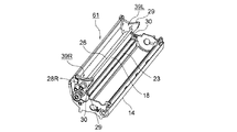
図1は本発明の第1の実施の形態における現像装置の要部を示す側面図、図6は本発明の第1の実施の形態における現像装置の組立工程を示す第1の斜視図、図7は本発明の第1の実施の形態における現像装置の組立工程を示す第2の斜視図、図8は本発明の第1の実施の形態における現像装置の要部を示す拡大図、図9は本発明の第1の実施の形態における現像装置の組立工程を示す第3の斜視図、図10は本発明の第1の実施の形態における現像装置の組立工程を示す第4の斜視図、図11は本発明の第1の実施の形態における現像装置の組立工程を示す第5の斜視図、図12は本発明の第1の実施の形態における現像装置の組立工程を示す第6の斜視図、図13は本発明の第1の実施の形態における現像装置の要部を示す分解斜視図、図14は本発明の第1の実施の形態におけるシール部材及びシールプレートを示す斜視図である。 FIG. 1 is a side view showing a main part of a developing device according to a first embodiment of the present invention, and FIG. 6 is a first perspective view showing an assembly process of the developing device according to the first embodiment of the present invention. 7 is a second perspective view showing the assembling process of the developing device in the first embodiment of the present invention, FIG. 8 is an enlarged view showing the main part of the developing device in the first embodiment of the present invention, FIG. FIG. 10 is a third perspective view showing an assembling process of the developing device in the first embodiment of the present invention. FIG. 10 is a fourth perspective view showing an assembling process of the developing device in the first embodiment of the present invention. FIG. 11 is a fifth perspective view showing the assembly process of the developing device according to the first embodiment of the present invention, and FIG. 12 is a sixth perspective view showing the assembly process of the developing device according to the first embodiment of the present invention. FIG. 13 and FIG. 13 are exploded perspective views showing essential parts of the developing device according to the first embodiment of the present invention, 14 is a perspective view showing a seal member and a seal plate in the first embodiment of the present invention.
図6において、31は供給ローラアッセンブリであり、該供給ローラアッセンブリ31は、供給ローラ18、攪拌バー26、供給ローラ18及び攪拌バー26の両端に当接させて配設され、前記供給ローラ18及び攪拌バー26の両端からトナーが漏れるのを防止するシール部材39L、39R、該シール部材39L、39Rを保持する保持部材としてのシールプレート28L、28Rを備え、前記供給ローラ18及び攪拌バー26の各シャフトは、シール部材39L、39R及びシールプレート28L、28Rを貫通させられ、図10に示されるように、サイドフレーム32L、32Rによって支持される。前記シール部材39L、39Rによって第1のシール部材が、フィルム23によって第2のシール部材が構成される。なお、前記シールプレート28L、28R及びシール部材39L、39Rは、用紙の搬送方向における上流側から下流側をみて、左側にシールプレート28L及びシール部材39Lが、右側にシールプレート28R及びシール部材39Rが配設される。
In FIG. 6,
前記シール部材39L、39Rは、それぞれ、供給ローラ18の両端面と当接させて配設された第1のシール要素としてのウレタンフォーム製のサイドスポンジ29、及び現像ローラ16の両端の外周面と当接させて配設された第2のシール要素としてのウレタンフォーム製のフェルトスポンジ30を備える。該フェルトスポンジ30は、前記サイドスポンジ29の円弧状の面に両面接着テープを介して、前記フィルム23の下側に潜り込むように取り付けられ、ウレタンフォーム部、及び該ウレタンフォーム部の表面に溶着され、現像ローラ16との当接面を構成するフェルトを備える。
The sealing
前記フィルム23は、供給ローラアッセンブリ31の長手方向におけるフェルトスポンジ30と対応する位置まで延在させて、前記ベースフレーム14の底面の貼着斜面に両面接着テープを介して貼着される。
The
また、図14に示されるように、シールプレート28L、28R(図1及び14においては、シールプレート28Rだけを示す。)には、ベースフレーム14との当接面の下端の近傍にベースフレーム14側に向けて係合部としての突起37が取り付けられるとともに、下端に下方に向けて凹部を形成する係合部38が形成される。前記突起37の下縁は、面取り又はR取りがされ、下縁は摺動面37aを構成する。
Further, as shown in FIG. 14, the seal plates 28 </ b> L and 28 </ b> R (only the seal plate 28 </ b> R is shown in FIGS. 1 and 14) have a
一方、図1、6及び13に示されるように、前記ベースフレーム14のシールプレート28L、28Rの側面と対向する面の前記突起37と対応する箇所に、突起37と係合する凹部、すなわち、穴35が形成され、ベースフレーム14のシールプレート28L、28Rの下面と対向する面に、前記係合部38と対応させて突部36が形成される。前記穴35及び突部36は、ベースフレーム14に供給ローラアッセンブリ31(供給ローラ18)を装着する際に、前記シールプレート28L、28R及びシール部材39L、39Rの移動を規制する規制部を構成する。なお、本実施の形態においては、シールプレート28L、28Rに突起37が配設され、係合部38が形成され、ベースフレーム14に穴35及び突部36が形成されるようになっているが、シールプレート28L、28Rに穴及び突部を形成し、ベースフレーム14に突起を配設し、係合部を形成することもできる。
On the other hand, as shown in FIGS. 1, 6, and 13, in a portion corresponding to the
前記感光体ドラム12Bk及び帯電ローラ13は、両端において、図11及び12に示されるように、前記ベースフレーム14に取り付けられたサイドフレーム32L、32Rによって回転自在に支持される。
The photosensitive drum 12Bk and the charging
次に、前記構成の現像装置10Bkの組立工程について説明する。 Next, an assembly process of the developing device 10Bk having the above configuration will be described.
まず、図6及び7に示されるように、前記供給ローラアッセンブリ31をフィルム23が貼着されたベースフレーム14に乗せる。次に、図9に示されるように、感光体ドラム12Bkを取り付け、該感光体ドラム12Bkに接触させて帯電ローラ13を乗せ、感光体ドラム12Bkと供給ローラ18との間に、感光体ドラム12Bk及び供給ローラ18に接触させて現像ローラ16を乗せる。これに伴って、現像ローラ16と、前記フィルム23及びフェルトスポンジ30とが当接させられ、この部分からトナーが漏れるのを防止する。
First, as shown in FIGS. 6 and 7, the
続いて、図10に示されるように、感光体ドラム12Bk、帯電ローラ13、現像ローラ16、供給ローラ18等の各ローラ類の軸受けを備え、かつ、各ローラ類の位置決めを行う前記サイドフレーム32L、32Rを左右両側から組み付けて、各ローラ類を挿入し、図11に示されるように、現像ブレード17を、現像ローラ16に当接させた状態で前記サイドフレーム32L、32Rに取り付ける。その結果、前記現像ローラ16と現像ブレード17とが、該現像ブレード17とシール部材39L、39Rとが接触し、ベースフレーム14、現像ブレード17、フィルム23及びシール部材39L、39Rによって包囲され、密閉された貯蔵室20が形成される。
Subsequently, as shown in FIG. 10, the side frame 32 </ b> L includes bearings for each of the rollers such as the photosensitive drum 12 </ b> Bk, the charging
最後に、図12に示されるように、アッパフレーム15を取り付け、該アッパフレーム15の開口15aに前記トナーカートリッジ21(図5)を装着することによって、現像装置10Bkの組立てが終了する。なお、前記アッパフレーム15の上端の開口15a内には、トナーカートリッジ21の下端部を収容する凹面部34が形成され、該凹面部34に前記開口部22と対応させて開口34aが形成される。
Finally, as shown in FIG. 12, the
ところで、供給ローラアッセンブリ31をベースフレーム14に取り付けるに当たり、シール部材39L、39Rに取り付けられたフェルトスポンジ30をフィルム23の下に潜り込ませた状態で供給ローラアッセンブリ31をベースフレーム14に装着した後に、感光体ドラム12を取り付け、帯電ローラ13及び現像ローラ16を乗せ、サイドフレーム32L、32Rを左右両側から組み付けるようになっているので、各サイドフレーム32L、32Rの軸受けに各ローラ類のシャフトを挿入するのが困難であり、挿入の動作を繰り返すうちに、前記供給ローラアッセンブリ31が前後上下方向に移動してしまうことがある。その場合、例えば、前記各フェルトスポンジ30がフィルム23に乗り上げてしまい、フィルム23によるシール性が低下し、各フェルトスポンジ30がフィルム23に乗り上げた部分、すなわち、供給ローラアッセンブリ31の両端からトナーが漏れて用紙上にこぼれ落ち、印刷面の両端に斑点状の汚れが発生してしまう。
By the way, when attaching the
そこで、本実施の形態においては、前述されたように、前記シールプレート28L、28Rに突起37が配設されるとともに、係合部38が形成され、ベースフレーム14に穴35及び突部36が形成されるようになっている。
Therefore, in the present embodiment, as described above, the
そして、前記供給ローラアッセンブリ31をベースフレーム14に装着する際に、突起37の摺動面37aをベースフレーム14の側面に沿って滑らせ、供給ローラアッセンブリ31を下降させ、フィルム23に各フェルトスポンジ30が乗り上げないように、前記穴35と突起37とを係合させ、前記突部36と係合部38とを係合させる。このようにして、供給ローラアッセンブリ31がベースフレーム14に取り付けられる。
When the
この場合、前記穴35と突起37との係合によって供給ローラアッセンブリ31の上下方向の移動が規制され、前記突部36と係合部38との係合によって供給ローラアッセンブリ31の前後方向の移動が規制される。したがって、サイドフレーム32L、32Rを組み付ける際に、供給ローラアッセンブリ31が前後上下に移動することがないので、各フェルトスポンジ30がフィルム23に乗り上げることがない。
In this case, the vertical movement of the
その結果、フィルム23によるシール性を向上させることができ、供給ローラアッセンブリ31の両端からトナーが漏れるのを防止することができるので、用紙の両端に斑点状の汚れが発生することがなくなり、画像品位を向上させることができる。
As a result, the sealing performance by the
次に、本発明の第2の実施の形態について説明する。なお、第1の実施の形態と同じ構造を有するものについては、同じ符号を付与することによってその説明を省略し、同じ構造を有することによる発明の効果については同実施の形態の効果を援用する。 Next, a second embodiment of the present invention will be described. In addition, about the thing which has the same structure as 1st Embodiment, the description is abbreviate | omitted by providing the same code | symbol, and the effect of the same embodiment is used about the effect of the invention by having the same structure. .
図15は本発明の第2の実施の形態における現像装置の要部を示す斜視図、図16は本発明の第2の実施の形態における現像装置の要部を示す第1の拡大図、図17は本発明の第2の実施の形態における現像装置の要部を示す側面図、図18は本発明の第2の実施の形態における現像装置の要部を示す第2の拡大図である。 FIG. 15 is a perspective view showing the main part of the developing device according to the second embodiment of the present invention, and FIG. 16 is a first enlarged view showing the main part of the developing device according to the second embodiment of the present invention. 17 is a side view showing the main part of the developing device according to the second embodiment of the present invention, and FIG. 18 is a second enlarged view showing the main part of the developing device according to the second embodiment of the present invention.
この場合、第1のケースとしてのベースフレーム44の側面において、第2のシール部材としてのフィルム23の両端部の上方の、保持部材としてのシールプレート48L、48Rの上面と対向する面に、内側に突出させて規制部としてのリブ49が形成される。該リブ49は、ベースフレーム44に供給ローラアッセンブリ41(供給部材としての供給ローラ18)を装着する際に、前記シールプレート48L、48R及び第1のシール部材としてのシール部材39L、39Rの移動を規制する。
In this case, on the side surface of the
また、供給ローラアッセンブリ41をベースフレーム44に真上から装着しようとしても、シールプレート48L、48Rの下端が前記リブ49と当接し、供給ローラアッセンブリ41の真上からの装着を阻止する。この場合、シールプレート48L、48Rの上面によって係合部が構成される。
Further, even if the
本実施の形態においては、供給ローラアッセンブリ41を、リブ49の下面に這わせるように、図17の矢印方向に回転させるようにして取り付ける必要があり、回転に伴って、各フェルトスポンジ30が自然とフィルム23の下に潜り込むので、供給ローラアッセンブリ41を確実に正しく取り付けることができる。
In the present embodiment, the
また、前記リブ49によって供給ローラアッセンブリ41の上下方向の移動が規制されるので、サイドフレーム32L、32Rを組み付ける際に、供給ローラアッセンブリ41が上下方向に移動することがなく、各フェルトスポンジ30がフィルム23に乗り上げることがない。
Further, since the movement of the
その結果、フィルム23によるシール性を向上させることができ、供給ローラアッセンブリ41の両端からトナーが漏れるのを防止することができるので、用紙の両端に斑点状の汚れが発生することがなくなり、画像品位を向上させることができる。
As a result, the sealing performance by the
次に、本発明の第3の実施の形態について説明する。なお、第1の実施の形態と同じ構造を有するものについては、同じ符号を付与することによってその説明を省略し、同じ構造を有することによる発明の効果については同実施の形態の効果を援用する。 Next, a third embodiment of the present invention will be described. In addition, about the thing which has the same structure as 1st Embodiment, the description is abbreviate | omitted by providing the same code | symbol, and the effect of the same embodiment is used about the effect of the invention by having the same structure. .
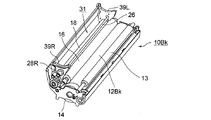
図19は本発明の第3の実施の形態における現像装置の要部を示す斜視図、図20は本発明の第3の実施の形態における現像装置の要部を示す第1の拡大図、図21は本発明の第2の実施の形態における現像装置の要部を示す第2の拡大図、図22は本発明の第3の実施の形態におけるシール部材及びシールプレートを示す斜視図、図23は本発明の第3の実施の形態における現像装置の要部を示す第3の拡大図である。 FIG. 19 is a perspective view showing the main part of the developing device according to the third embodiment of the present invention. FIG. 20 is a first enlarged view showing the main part of the developing device according to the third embodiment of the present invention. 21 is a second enlarged view showing a main part of the developing device according to the second embodiment of the present invention, FIG. 22 is a perspective view showing a seal member and a seal plate according to the third embodiment of the present invention, and FIG. These are the 3rd enlarged views which show the principal part of the developing device in the 3rd Embodiment of this invention.
図において、14は第1のケースとしてのベースフレーム、39L、39Rは第1のシール部材としてのシール部材であり、該シール部材39L、39Rは保持部材としてのシールプレート28L、28Rによって保持される。前記ベースフレーム14には、長手方向における両端において、図20に示されるように、シール部材39L、39Rの各フェルトスポンジ30が挿入される位置の手前までの間に延在させて、第1の貼着部としての貼付面71が形成され、該貼付面71にフィルム23が貼り付けられる。そして、該フィルム23は、前記シール部材39L、39Rの各フェルトスポンジ30が挿入される位置間の長さを有し、図21に示されるように、長手方向に沿って前記貼付面71に貼り付けられると、フィルム23の両端において、接着面が各フェルトスポンジ30の幅分だけ剥き出しの状態になる。
In the figure, 14 is a base frame as a first case, 39L and 39R are seal members as first seal members, and the
また、前記シール部材39L、39Rは、フェルトスポンジ30の下方に、第2の貼着部としてのリブ72を備える。該リブ72は、貼付面71と同じ高さを有し、フェルトスポンジ30の幅方向の全域にわたって形成される。この場合、前記フィルム23の両端及びリブ72によって、シールプレート28L、28Rの移動を規制する規制部が構成される。
The
したがって、ベースフレーム14に供給ローラアッセンブリ31を組み付ける工程において、供給ローラアッセンブリ31の両端において、フェルトスポンジ30をフィルム23の下方に潜り込ませ、供給ローラアッセンブリ31を組み込むと、フィルム23の両端の剥き出しになった接着面にリブ72の面が接触し、フィルム23は、リブ72に貼着されて固定される。これにより、サイドフレーム32L、32Rを組み付ける際に、供給ローラアッセンブリ31が上下方向に移動することがなく、各フェルトスポンジ30がフィルム23に乗り上げることがない。したがって、供給ローラアッセンブリ31の両端においてトナー漏れが発生するのを防止することができる。
Therefore, in the process of assembling the
次に、本発明の第4の実施の形態について説明する。なお、第1の実施の形態と同じ構造を有するものについては、同じ符号を付与することによってその説明を省略し、同じ構造を有することによる発明の効果については同実施の形態の効果を援用する。 Next, a fourth embodiment of the present invention will be described. In addition, about the thing which has the same structure as 1st Embodiment, the description is abbreviate | omitted by providing the same code | symbol, and the effect of the same embodiment is used about the effect of the invention by having the same structure. .
図24は本発明の第4の実施の形態における現像装置の要部を示す斜視図、図25は本発明の第4の実施の形態における現像装置の要部を示す拡大図である。 FIG. 24 is a perspective view showing the main part of the developing device according to the fourth embodiment of the present invention, and FIG. 25 is an enlarged view showing the main part of the developing device according to the fourth embodiment of the present invention.
この場合、第2のシール部材としてのフィルム73は、長手方向の両端部において、供給ローラアッセンブリ31の両端の、第2のシール要素としてのフェルトスポンジ30と対応する位置に、フェルトスポンジ30と同一の幅を有し、かつ、現像剤担持体としての現像ローラ16の回転方向(図24及び25において上方)に延びる伸長部74を有する。なお、該伸長部74によって、保持部材としてのシールプレート28L、28Rの移動を規制する規制部が構成される。
In this case, the
この場合、画像形成部としての現像装置10Bkにおいて、第1のケースとしてのベースフレーム14に供給ローラアッセンブリ31を組み付ける工程では、供給ローラアッセンブリ31の両端のフェルトスポンジ30を伸長部74の下方に潜り込ませることによって、供給ローラアッセンブリ31の配置は終了する。
In this case, in the developing device 10Bk as the image forming unit, in the process of assembling the
これにより、サイドフレーム32L、32Rを組み付ける際に、供給ローラアッセンブリ31が上下方向に移動することがなく、各フェルトスポンジ30がフィルム73に乗り上げることがない。したがって、供給ローラアッセンブリ31の両端においてトナー漏れが発生するのを防止することができる。
Thus, when the side frames 32L and 32R are assembled, the
前記各実施の形態においては、画像形成装置のうちのカラーのプリンタについて説明したが、単色のプリンタ、複写機、ファクシミリ装置、複合機等の画像形成装置に適用することができる。 In each of the above-described embodiments, the color printer of the image forming apparatus has been described. However, the present invention can be applied to an image forming apparatus such as a monochrome printer, a copying machine, a facsimile machine, or a multifunction machine.
なお、本発明は前記実施の形態に限定されるものではなく、本発明の趣旨に基づいて種々変形させることが可能であり、それらを本発明の範囲から排除するものではない。 In addition, this invention is not limited to the said embodiment, It can change variously based on the meaning of this invention, and does not exclude them from the scope of the present invention.
10Bk、10Y、10M、10C 現像装置
12BK、12Y、12M、12C 感光体ドラム
14、44 ベースフレーム
15 アッパフレーム
16 現像ローラ
18 供給ローラ
23、73 フィルム
28L、28R、48L、48R シールプレート
31、41 供給ローラアッセンブリ
35 穴
36 突部
37 突起
38 係合部
39L、39R シール部材
49、72 リブ
74 伸長部
10Bk, 10Y, 10M, 10C Developing devices 12BK, 12Y, 12M, 12C Photosensitive drums 14, 44
Claims (8)
(b)該像担持体の表面に形成された静電潜像に現像剤を付着させて現像する現像剤担持体と、
(c)該現像剤担持体に現像剤を供給する供給部材と、
(d)前記現像剤担持体及び供給部材の両端に当接させて配設された第1のシール部材と、
(e)該第1のシール部材を保持する保持部材と、
(f)前記供給部材、第1のシール部材及び保持部材から成る供給部材アッセンブリ、並びに前記現像剤担持体を装着するためのケースと、
(g)該ケース内に長手方向に配設され、前記現像剤担持体が装着されたときに、現像剤担持体の下面に当接させられる第2のシール部材とを有するとともに、
(h)前記保持部材に第1、第2の係合部が、前記ケースに前記第1、第2の係合部とそれぞれ係合させられる第1、第2の規制部が形成され、
(i)前記供給部材アッセンブリを前記ケースに装着する際に、前記第1、第2の係合部と第1、第2の規制部とがそれぞれ係合させられることによって、前記供給部材アッセンブリの移動が規制されることを特徴とする現像装置。 (A) an image carrier;
(B) a developer carrier for developing the developer by attaching the developer to the electrostatic latent image formed on the surface of the image carrier;
(C) a supply member for supplying a developer to the developer carrying member;
(D) a first seal member disposed in contact with both ends of the developer carrier and the supply member;
(E) a holding member that holds the first seal member;
(F) a supply member assembly comprising the supply member, a first seal member and a holding member, and a case for mounting the developer carrier ;
(G) disposed longitudinally within the case, when the developer carrying member is mounted, with a second seal members abutting on a lower surface of the developer carrying member,
(H) The holding member is formed with first and second engaging portions, and the case is formed with first and second restricting portions that are engaged with the first and second engaging portions, respectively.
(I) When the supply member assembly is mounted on the case, the first and second engaging portions and the first and second restricting portions are engaged with each other, whereby the supply member assembly is A developing device characterized in that movement is restricted .
(b)前記第1、第2の規制部の一方は凹部であり、他方は突部である請求項1〜4のいずれか1項に記載の現像装置。 (A) before SL one of the first and second engagement portions are projections, and the other Ri recess der,
(B) the first, a one recess of the second restricting portion and the other developing device according to any one of claims 1 to 4 Ru projection der.
(b)該像担持体の表面に形成された静電潜像に現像剤を付着させて現像する現像剤担持体と、
(c)該現像剤担持体に現像剤を供給する供給部材と、
(d)前記現像剤担持体及び供給部材の両端に当接させて配設された第1のシール部材と、
(e)該第1のシール部材を保持する保持部材と、
(f)前記供給部材、第1のシール部材及び保持部材から成る供給部材アッセンブリ、並びに前記現像剤担持体を装着するためのケースと、
(g)該ケース内に長手方向に配設され、前記供給部材アッセンブリ及び現像剤担持体が装着されたときに、現像剤担持体の下面に当接させられる第2のシール部材とを有するとともに、
(h)前記保持部材に第1、第2の係合部が、前記ケースに前記第1、第2の係合部とそれぞれ係合させられる第1、第2の規制部が形成され、
(i)前記供給部材アッセンブリを前記ケースに装着する際に、前記第1、第2の係合部と第1、第2の規制部とがそれぞれ係合させられることによって、前記供給部材アッセンブリの移動が規制され、
(j)前記第2のシール部材の両端は、第1のシール部材に形成された貼着部に貼着されることを特徴とする現像装置。 (A) an image carrier;
(B) a developer carrier for developing the developer by attaching the developer to the electrostatic latent image formed on the surface of the image carrier;
(C) a supply member for supplying a developer to the developer carrying member;
(D) a first seal member disposed in contact with both ends of the developer carrier and the supply member;
(E) a holding member that holds the first seal member;
(F) a supply member assembly comprising the supply member, a first seal member and a holding member, and a case for mounting the developer carrier ;
(G) disposed longitudinally within the case, when the supply member assembly and the developer carrying member is mounted, and a second seal members abutting on a lower surface of the developer carrying member With
(H) The holding member is formed with first and second engaging portions, and the case is formed with first and second restricting portions that are engaged with the first and second engaging portions, respectively.
(I) When the supply member assembly is mounted on the case, the first and second engaging portions and the first and second restricting portions are engaged with each other, whereby the supply member assembly is Movement is restricted,
(J) the two ends of the second seal member, developing device, characterized in that it is stuck to the adhesive portion formed on the first sealing member.
(b)該像担持体の表面に形成された静電潜像に現像剤を付着させて現像する現像剤担持体と、
(c)該現像剤担持体に現像剤を供給する供給部材と、
(d)前記現像剤担持体及び供給部材の両端に当接させて配設された第1のシール部材と、
(e)該第1のシール部材を保持する保持部材と、
(f)前記供給部材、第1のシール部材及び保持部材から成る供給部材アッセンブリ、並びに前記現像剤担持体を装着するためのケースと、
(g)該ケース内に長手方向に配設され、前記供給部材アッセンブリ及び現像剤担持体が装着されたときに、現像剤担持体の下面に当接させられる第2のシール部材とを有するとともに、
(h)前記保持部材に第1、第2の係合部が、前記ケースに前記第1、第2の係合部とそれぞれ係合させられる第1、第2の規制部が形成され、
(i)前記供給部材アッセンブリを前記ケースに装着する際に、前記第1、第2の係合部と第1、第2の規制部とがそれぞれ係合させられることによって、前記供給部材アッセンブリの移動が規制され、
(j)前記第2のシール部材の両端に、第1のシール部材に沿って伸長部が形成されることを特徴とする現像装置。 (A) an image carrier;
(B) a developer carrier for developing the developer by attaching the developer to the electrostatic latent image formed on the surface of the image carrier;
(C) a supply member for supplying a developer to the developer carrying member;
(D) a first seal member disposed in contact with both ends of the developer carrier and the supply member;
(E) a holding member that holds the first seal member;
(F) a supply member assembly comprising the supply member, a first seal member and a holding member, and a case for mounting the developer carrier ;
(G) disposed longitudinally within the case, when the supply member assembly and the developer carrying member is mounted, and a second seal members abutting on a lower surface of the developer carrying member With
(H) The holding member is formed with first and second engaging portions, and the case is formed with first and second restricting portions that are engaged with the first and second engaging portions, respectively.
(I) When the supply member assembly is mounted on the case, the first and second engaging portions and the first and second restricting portions are engaged with each other, whereby the supply member assembly is Movement is restricted,
(J) at both ends of the second sealing member, a developing device, characterized in that extension portions along the first seal member is formed.
Priority Applications (2)
| Application Number | Priority Date | Filing Date | Title |
|---|---|---|---|
| JP2006066212A JP5052800B2 (en) | 2005-09-30 | 2006-03-10 | Developing device and image forming apparatus |
| US11/520,620 US7447463B2 (en) | 2005-09-30 | 2006-09-14 | Developing device and image forming apparatus |
Applications Claiming Priority (3)
| Application Number | Priority Date | Filing Date | Title |
|---|---|---|---|
| JP2005289081 | 2005-09-30 | ||
| JP2005289081 | 2005-09-30 | ||
| JP2006066212A JP5052800B2 (en) | 2005-09-30 | 2006-03-10 | Developing device and image forming apparatus |
Publications (3)
| Publication Number | Publication Date |
|---|---|
| JP2007121989A JP2007121989A (en) | 2007-05-17 |
| JP2007121989A5 JP2007121989A5 (en) | 2009-02-05 |
| JP5052800B2 true JP5052800B2 (en) | 2012-10-17 |
Family
ID=37902084
Family Applications (1)
| Application Number | Title | Priority Date | Filing Date |
|---|---|---|---|
| JP2006066212A Active JP5052800B2 (en) | 2005-09-30 | 2006-03-10 | Developing device and image forming apparatus |
Country Status (2)
| Country | Link |
|---|---|
| US (1) | US7447463B2 (en) |
| JP (1) | JP5052800B2 (en) |
Families Citing this family (4)
| Publication number | Priority date | Publication date | Assignee | Title |
|---|---|---|---|---|
| JP5094152B2 (en) * | 2007-02-13 | 2012-12-12 | キヤノン株式会社 | Image forming apparatus |
| JP5525469B2 (en) * | 2011-02-28 | 2014-06-18 | 株式会社沖データ | Image forming unit and image forming apparatus |
| JP5467656B2 (en) | 2011-09-20 | 2014-04-09 | 株式会社沖データ | Developing device and image forming apparatus |
| JP6112298B2 (en) * | 2013-03-01 | 2017-04-12 | 株式会社リコー | Developing device, process unit, and image forming apparatus |
Family Cites Families (10)
| Publication number | Priority date | Publication date | Assignee | Title |
|---|---|---|---|---|
| JP3483091B2 (en) * | 1996-07-31 | 2004-01-06 | 株式会社リコー | Image forming device |
| JP3425053B2 (en) * | 1997-02-27 | 2003-07-07 | ブラザー工業株式会社 | Developing device |
| JP2000131940A (en) * | 1998-10-27 | 2000-05-12 | Canon Inc | Developing device, developing cartridge and image forming device |
| US6496668B2 (en) * | 1999-07-14 | 2002-12-17 | Brother Kogyo Kabushiki Kaisha | Image developing device with sealing members for preventing toner leakage |
| EP2759887A3 (en) * | 1999-08-23 | 2014-11-26 | Brother Kogyo Kabushiki Kaisha | Developing device, process cartridge, and image forming apparatus |
| JP2002108089A (en) | 2000-09-29 | 2002-04-10 | Oki Data Corp | Developing device |
| JP3936582B2 (en) * | 2001-12-25 | 2007-06-27 | ブラザー工業株式会社 | Developing device and image forming apparatus |
| JP2005215551A (en) * | 2004-01-30 | 2005-08-11 | Ricoh Co Ltd | Development device, process cartridge and image forming apparatus |
| JP2005234144A (en) * | 2004-02-18 | 2005-09-02 | Sharp Corp | Development apparatus and printer |
| JP4454402B2 (en) * | 2004-06-14 | 2010-04-21 | 株式会社沖データ | Developing device and image forming apparatus |
-
2006
- 2006-03-10 JP JP2006066212A patent/JP5052800B2/en active Active
- 2006-09-14 US US11/520,620 patent/US7447463B2/en active Active
Also Published As
| Publication number | Publication date |
|---|---|
| JP2007121989A (en) | 2007-05-17 |
| US7447463B2 (en) | 2008-11-04 |
| US20070077084A1 (en) | 2007-04-05 |
Similar Documents
| Publication | Publication Date | Title |
|---|---|---|
| JP4684732B2 (en) | Electrophotographic image forming apparatus and process cartridge | |
| JP4227626B2 (en) | Developer container, cartridge, and developer container manufacturing method | |
| JP4806265B2 (en) | Exchange unit and image forming apparatus | |
| JP5063792B2 (en) | Developing device, process cartridge, developing device, and process cartridge remanufacturing method | |
| JP2008158348A (en) | Developer container, assembling and regenerating method thereof | |
| JP2006251145A (en) | Cleaning device, developing device, process cartridge and electrophotographic image forming apparatus | |
| JP4538026B2 (en) | Charging device, image forming unit, and image forming apparatus | |
| JP5052800B2 (en) | Developing device and image forming apparatus | |
| JP4463083B2 (en) | Color image forming apparatus | |
| JP4842683B2 (en) | Image forming apparatus | |
| JP4911728B2 (en) | Image forming apparatus | |
| JP2013250514A (en) | Development apparatus, process cartridge, and image formation apparatus | |
| JP5020109B2 (en) | Developing device, process cartridge, image forming apparatus, color image forming apparatus | |
| JP2006259343A (en) | Developing device and image forming apparatus | |
| JP2008089808A (en) | Developing device and image forming apparatus | |
| JP5077626B2 (en) | Image forming apparatus and image forming unit | |
| JP2007148058A (en) | Image forming apparatus | |
| JP2007025345A (en) | Developing device, process cartridge and image forming apparatus | |
| JP5908434B2 (en) | Image forming apparatus | |
| JP4673639B2 (en) | Image forming apparatus | |
| JP4391272B2 (en) | Developing cartridge and image forming apparatus | |
| US20060204277A1 (en) | Image forming apparatus having a simple cassette of image bearing photoconductors | |
| JP2011022618A (en) | Electrophotographic image-forming apparatus and process cartridge | |
| US10488785B2 (en) | Developing unit, process cartridge, and image forming apparatus including process cartridge | |
| JP5280815B2 (en) | Developing device and image forming apparatus |
Legal Events
| Date | Code | Title | Description |
|---|---|---|---|
| A521 | Request for written amendment filed |
Free format text: JAPANESE INTERMEDIATE CODE: A523 Effective date: 20081216 |
|
| A621 | Written request for application examination |
Free format text: JAPANESE INTERMEDIATE CODE: A621 Effective date: 20081216 |
|
| A977 | Report on retrieval |
Free format text: JAPANESE INTERMEDIATE CODE: A971007 Effective date: 20110401 |
|
| A131 | Notification of reasons for refusal |
Free format text: JAPANESE INTERMEDIATE CODE: A131 Effective date: 20111220 |
|
| A521 | Request for written amendment filed |
Free format text: JAPANESE INTERMEDIATE CODE: A523 Effective date: 20120217 |
|
| TRDD | Decision of grant or rejection written | ||
| A01 | Written decision to grant a patent or to grant a registration (utility model) |
Free format text: JAPANESE INTERMEDIATE CODE: A01 Effective date: 20120724 |
|
| A01 | Written decision to grant a patent or to grant a registration (utility model) |
Free format text: JAPANESE INTERMEDIATE CODE: A01 |
|
| A61 | First payment of annual fees (during grant procedure) |
Free format text: JAPANESE INTERMEDIATE CODE: A61 Effective date: 20120725 |
|
| R150 | Certificate of patent or registration of utility model |
Ref document number: 5052800 Country of ref document: JP Free format text: JAPANESE INTERMEDIATE CODE: R150 Free format text: JAPANESE INTERMEDIATE CODE: R150 |
|
| FPAY | Renewal fee payment (event date is renewal date of database) |
Free format text: PAYMENT UNTIL: 20150803 Year of fee payment: 3 |
|
| S111 | Request for change of ownership or part of ownership |
Free format text: JAPANESE INTERMEDIATE CODE: R313111 |
|
| R350 | Written notification of registration of transfer |
Free format text: JAPANESE INTERMEDIATE CODE: R350 |