JP5046523B2 - Position measuring device - Google Patents
Position measuring device Download PDFInfo
- Publication number
- JP5046523B2 JP5046523B2 JP2006031779A JP2006031779A JP5046523B2 JP 5046523 B2 JP5046523 B2 JP 5046523B2 JP 2006031779 A JP2006031779 A JP 2006031779A JP 2006031779 A JP2006031779 A JP 2006031779A JP 5046523 B2 JP5046523 B2 JP 5046523B2
- Authority
- JP
- Japan
- Prior art keywords
- impulse signal
- scale
- signal detector
- reference impulse
- incremental
- Prior art date
- Legal status (The legal status is an assumption and is not a legal conclusion. Google has not performed a legal analysis and makes no representation as to the accuracy of the status listed.)
- Active
Links
- 230000005540 biological transmission Effects 0.000 claims description 46
- 238000005259 measurement Methods 0.000 claims description 21
- 230000000737 periodic effect Effects 0.000 claims description 21
- 238000001514 detection method Methods 0.000 claims description 17
- 238000002834 transmittance Methods 0.000 claims description 11
- 230000001419 dependent effect Effects 0.000 claims description 7
- 230000003287 optical effect Effects 0.000 claims description 5
- 238000002310 reflectometry Methods 0.000 claims description 3
- 230000007704 transition Effects 0.000 description 5
- 238000005286 illumination Methods 0.000 description 4
- 238000012935 Averaging Methods 0.000 description 2
- 230000000694 effects Effects 0.000 description 2
- 238000001914 filtration Methods 0.000 description 2
- 238000000034 method Methods 0.000 description 2
- 241000669003 Aspidiotus destructor Species 0.000 description 1
- XUIMIQQOPSSXEZ-UHFFFAOYSA-N Silicon Chemical compound [Si] XUIMIQQOPSSXEZ-UHFFFAOYSA-N 0.000 description 1
- 230000009471 action Effects 0.000 description 1
- 229910021417 amorphous silicon Inorganic materials 0.000 description 1
- 238000004458 analytical method Methods 0.000 description 1
- 238000003491 array Methods 0.000 description 1
- 238000011109 contamination Methods 0.000 description 1
- 238000013461 design Methods 0.000 description 1
- 238000006073 displacement reaction Methods 0.000 description 1
- 238000011156 evaluation Methods 0.000 description 1
- 230000007717 exclusion Effects 0.000 description 1
- 230000004907 flux Effects 0.000 description 1
- 239000011521 glass Substances 0.000 description 1
- 230000003993 interaction Effects 0.000 description 1
- 239000003550 marker Substances 0.000 description 1
- 230000009467 reduction Effects 0.000 description 1
- 230000004044 response Effects 0.000 description 1
- 229910052710 silicon Inorganic materials 0.000 description 1
- 239000010703 silicon Substances 0.000 description 1
- 238000004513 sizing Methods 0.000 description 1
- 239000013589 supplement Substances 0.000 description 1
Images


Classifications
-
- G—PHYSICS
- G01—MEASURING; TESTING
- G01D—MEASURING NOT SPECIALLY ADAPTED FOR A SPECIFIC VARIABLE; ARRANGEMENTS FOR MEASURING TWO OR MORE VARIABLES NOT COVERED IN A SINGLE OTHER SUBCLASS; TARIFF METERING APPARATUS; MEASURING OR TESTING NOT OTHERWISE PROVIDED FOR
- G01D5/00—Mechanical means for transferring the output of a sensing member; Means for converting the output of a sensing member to another variable where the form or nature of the sensing member does not constrain the means for converting; Transducers not specially adapted for a specific variable
- G01D5/26—Mechanical means for transferring the output of a sensing member; Means for converting the output of a sensing member to another variable where the form or nature of the sensing member does not constrain the means for converting; Transducers not specially adapted for a specific variable characterised by optical transfer means, i.e. using infrared, visible, or ultraviolet light
- G01D5/32—Mechanical means for transferring the output of a sensing member; Means for converting the output of a sensing member to another variable where the form or nature of the sensing member does not constrain the means for converting; Transducers not specially adapted for a specific variable characterised by optical transfer means, i.e. using infrared, visible, or ultraviolet light with attenuation or whole or partial obturation of beams of light
- G01D5/34—Mechanical means for transferring the output of a sensing member; Means for converting the output of a sensing member to another variable where the form or nature of the sensing member does not constrain the means for converting; Transducers not specially adapted for a specific variable characterised by optical transfer means, i.e. using infrared, visible, or ultraviolet light with attenuation or whole or partial obturation of beams of light the beams of light being detected by photocells
- G01D5/347—Mechanical means for transferring the output of a sensing member; Means for converting the output of a sensing member to another variable where the form or nature of the sensing member does not constrain the means for converting; Transducers not specially adapted for a specific variable characterised by optical transfer means, i.e. using infrared, visible, or ultraviolet light with attenuation or whole or partial obturation of beams of light the beams of light being detected by photocells using displacement encoding scales
- G01D5/34746—Linear encoders
-
- G—PHYSICS
- G01—MEASURING; TESTING
- G01D—MEASURING NOT SPECIALLY ADAPTED FOR A SPECIFIC VARIABLE; ARRANGEMENTS FOR MEASURING TWO OR MORE VARIABLES NOT COVERED IN A SINGLE OTHER SUBCLASS; TARIFF METERING APPARATUS; MEASURING OR TESTING NOT OTHERWISE PROVIDED FOR
- G01D5/00—Mechanical means for transferring the output of a sensing member; Means for converting the output of a sensing member to another variable where the form or nature of the sensing member does not constrain the means for converting; Transducers not specially adapted for a specific variable
- G01D5/12—Mechanical means for transferring the output of a sensing member; Means for converting the output of a sensing member to another variable where the form or nature of the sensing member does not constrain the means for converting; Transducers not specially adapted for a specific variable using electric or magnetic means
- G01D5/244—Mechanical means for transferring the output of a sensing member; Means for converting the output of a sensing member to another variable where the form or nature of the sensing member does not constrain the means for converting; Transducers not specially adapted for a specific variable using electric or magnetic means influencing characteristics of pulses or pulse trains; generating pulses or pulse trains
- G01D5/245—Mechanical means for transferring the output of a sensing member; Means for converting the output of a sensing member to another variable where the form or nature of the sensing member does not constrain the means for converting; Transducers not specially adapted for a specific variable using electric or magnetic means influencing characteristics of pulses or pulse trains; generating pulses or pulse trains using a variable number of pulses in a train
- G01D5/2454—Encoders incorporating incremental and absolute signals
- G01D5/2455—Encoders incorporating incremental and absolute signals with incremental and absolute tracks on the same encoder
- G01D5/2457—Incremental encoders having reference marks
Description
この発明は、位置に依存した走査信号を生成するのに、特に少なくとも一つの基準インパルス信号を生成するのに適した位置測定装置に関する。 The present invention relates to a position measuring device suitable for generating a position-dependent scanning signal, in particular for generating at least one reference impulse signal.
周知の位置測定装置は、通常二つの互いに動く部分の相対的な偏差に関するインクリメンタル信号の他に、一つ以上の所定の基準位置における基準インパルス信号も供給する。この基準インパルス信号によって、位置測定装置の走査ユニットと基準尺に繋がっている互いに動く部分の所定の相対的な位置に関して、さもなければ相対的に行われた位置測定での精確な絶対的な関係を構築することができるものである。これらの互いに動く構成要素は、例えば数値制御工作機械の加工物と工具である。 Known position measuring devices usually supply a reference impulse signal at one or more predetermined reference positions, in addition to an incremental signal relating to the relative deviation of the two moving parts. With this reference impulse signal, a precise absolute relationship with respect to the predetermined relative position of the moving part connected to the scanning unit of the position measuring device and the reference scale, otherwise relative to the position measurement. Is something that can be built. These moving components are, for example, numerically controlled machine tool workpieces and tools.
ここで、基準尺の側での基準指標の構成に関して、一連の周知の可能性が有る。即ち、これらの指標は、例えば、インクリメンタル目盛トラックの側方に隣接する形で基準尺上に配置することができる。しかし、この変化形態では、万一基準尺と走査ユニットが基準尺の面又は走査面に対して垂直な軸の周りに捻れた場合又は誤って調整された場合、結果として得られる基準インパルス信号のインクリメンタル信号の所定の周期への精確な対応が、場合によっては最早保証されないということが基本的に問題である。この問題点を回避するために、例えば、特許文献1により、一つ以上の基準指標を基準尺上のインクリメンタル目盛トラックに統合することが知られている。それに関して、インクリメンタル目盛の測定区間に沿った所望の基準位置において、例えば、周期的なインクリメンタル目盛トラックの中の一つ以上の目盛を省くことができる。
Here, there is a series of known possibilities regarding the configuration of the reference index on the reference scale side. That is, these indexes can be arranged on the reference scale in a form adjacent to the side of the incremental scale track, for example. However, in this variation, if the reference scale and scanning unit are twisted or misadjusted around the reference scale plane or an axis perpendicular to the scan plane, the resulting reference impulse signal The basic problem is that an accurate response to the predetermined period of the incremental signal is no longer guaranteed in some cases. In order to avoid this problem, for example,
物理的な走査原理に関して、光学式位置測定装置は、使用する光源の前にコリメーターレンズを持つシステムと持たないシステムとに分類される。コリメーターレンズを用いていない場合、通常発散照明と称される。このような位置測定装置は、特にコンパクトな全体構造に関して有利である。 Regarding the physical scanning principle, the optical position measuring device is classified into a system having a collimator lens in front of a light source to be used and a system having no collimator lens. When no collimator lens is used, it is usually called divergent illumination. Such a position measuring device is particularly advantageous for a compact overall structure.
ここで、特許文献2と3により、既に発散照明の位置測定装置において、基準尺上のインクリメンタル目盛トラックに統合された基準指標の走査により得られる基準インパルス信号を生成する解決法が周知である。
Here, according to
しかし、これらの特許文献に提案されている基準インパルス信号を生成するための変化形態は、基準インパルス信号の生成における出来る限り高い効率、インクリメンタル信号の低い雑音、或いは生成されたインクリメンタル信号の基準インパルス信号に対する影響の出来る限り大幅な排除に関して、未だ最適化されていないことが分かっている。
以上のことから、この発明の課題は、コリメーターレンズを持たず、基準指標を統合したインクリメンタル目盛トラックの走査から基準インパルス信号を確実に生成することを可能とする位置測定装置を提供することである。この場合、インクリメンタル信号の生成が、出来る限り小さい擾乱を受けるようにすべきである。 In view of the above, an object of the present invention is to provide a position measuring device that does not have a collimator lens and that can reliably generate a reference impulse signal from scanning of an incremental scale track integrated with a reference index. is there. In this case, the generation of the incremental signal should be subjected to as little disturbance as possible.
この課題は、請求項1の特徴を述べた部分における特徴を持つ位置測定装置によって解決される。
This problem is solved by a position measuring device having features in the part of the
この発明による位置測定装置の有利な実施構成は、請求項1に従属する請求項に挙げられた措置から明らかとなる。
Advantageous implementations of the position measuring device according to the invention emerge from the measures listed in the claims dependent on
ここで、この発明では、基準インパルス信号検出器ユニットの構成は、この構成が、基準位置において振幅変調された、検出面に生じる縞模様に対してバンドパスフィルターとして作用し、そのようにして所望の幅の基準インパルス信号を生成するものと規定する。 Here, in the present invention, the configuration of the reference impulse signal detector unit is such that this configuration acts as a bandpass filter on the stripe pattern generated on the detection surface, which is amplitude-modulated at the reference position, and is thus desired. It is defined that a reference impulse signal having a width of 2 is generated.
この基準インパルス信号検出器ユニットのバンドパスフィルターとしての作用の結果、走査されたインクリメンタル目盛の基本周波数が、より高い高調波を含めて、専ら比較的ゆっくりと変化する信号成分と同様に、検出面における振幅変調された信号から排除されることとなる。それに対して、インクリメンタル信号の基本周波数の約半分の周波数帯域における信号成分は、大幅に低減されずに、所望の幅を持つ基準インパルス信号を生成するために集積される。こうすることによって、検出した走査信号から、基準インパルス信号を生成するのに適した周波数帯域だけが、フィルターにより取り出される。 As a result of the operation of this reference impulse signal detector unit as a bandpass filter, the fundamental frequency of the scanned incremental scale, including higher harmonics, is similar to the signal component that changes relatively slowly, including the higher harmonics. Are excluded from the amplitude-modulated signal. In contrast, signal components in a frequency band that is approximately half the fundamental frequency of the incremental signal are not significantly reduced, but are integrated to generate a reference impulse signal having a desired width. By doing so, only the frequency band suitable for generating the reference impulse signal is extracted from the detected scanning signal by the filter.
実現可能な実施構成では、場合によっては複数の基準インパルス信号検出器ユニットの中の一つが、一方において互いに所定の幾何学的な形に配置されるとともに、他方において所望の基準インパルス信号を生成するのに適した形に接続された、三つの基準インパルス信号検出器エレメントを有する。この場合、有利には、中央に配置された基準インパルス信号検出器エレメントの他に、インクリメンタルトラックにおいて、この中央に配置された基準インパルス信号検出器エレメントに対して測定方向に対称的に配置された二つの基準インパルス信号検出器エレメントが配備され、これらの二つの検出器エレメントは、それぞれ360°の整数倍のずれを持つ走査信号を生成するものである。一方における中央に配置された基準インパルス信号検出器エレメントと他方におけるこのエレメントに対して対称的に配置された二つの基準インパルス信号検出器エレメントとを、差分を取る形で接続するものと規定する。この最終的に得られた差分信号が、基準インパルス信号となる。 In a possible implementation, in some cases one of a plurality of reference impulse signal detector units is arranged in a predetermined geometric shape on the one hand and generates the desired reference impulse signal on the other hand. Three reference impulse signal detector elements connected in a suitable form. In this case, advantageously, in addition to the centrally arranged reference impulse signal detector element, the incremental track is arranged symmetrically in the measuring direction with respect to this centrally arranged reference impulse signal detector element. Two reference impulse signal detector elements are provided, each of which produces a scan signal having an integer multiple of 360 °. It is defined that a reference impulse signal detector element arranged at the center on one side and two reference impulse signal detector elements arranged symmetrically with respect to this element on the other side are connected in a manner of taking a difference. This finally obtained difference signal becomes a reference impulse signal.
この発明の有利な実施構成では、中央に配置された基準インパルス信号検出器エレメントの幅を、このエレメントに対して対称的に配置された二つの基準インパルス信号検出器エレメントの幅の2倍の大きさに選定する。 In an advantageous embodiment of the invention, the width of the centrally arranged reference impulse signal detector element is twice as large as the width of two reference impulse signal detector elements arranged symmetrically with respect to this element. Select.
基準尺の側又はインクリメンタル目盛トラックには、有利には少なくとも一つの、所謂明視野を挿入することによって、統合された基準指標に該当する部分領域の非周期的な配列を実現する。この場合、この明視野は、インクリメンタル目盛トラックの周期性を乱すものであり、反射光式システムでは反射率の高い部分領域で、或いは透過光式システムでは透過率の高い部分領域で構成される。 By inserting at least one so-called bright field on the side of the reference scale or on the incremental scale track, an aperiodic arrangement of the partial areas corresponding to the integrated reference index is realized. In this case, this bright field disturbs the periodicity of the incremental graduation track, and is composed of a partial region having a high reflectance in a reflected light system or a partial region having a high transmittance in a transmitted light system.
第一の実現可能な実施構成では、この明視野の測定方向に対する幅を、有利には、インクリメンタル目盛トラックの目盛周期の1.5倍の大きさに選定する。こうすることによって、本来不透明な部分領域を反射又は透過する領域に変えている。そのことは、インクリメンタル目盛トラックの周期性を最小限度に変化させると同時に、基準インパルスの確実な生成を保証することとなる。別の実施構成では、この明視野の幅は、インクリメンタル目盛トラックの目盛周期の2倍の大きさに選定することもできる。 In a first possible implementation, the width of the bright field with respect to the measuring direction is advantageously chosen to be 1.5 times the scale period of the incremental scale track. In this way, the originally opaque partial area is changed to a reflective or transmissive area. This guarantees a reliable generation of the reference impulses while at the same time changing the periodicity of the incremental graduation tracks to a minimum. In another implementation, the bright field width may be selected to be twice the scale period of the incremental scale track.
この明視野とこれに隣接する反射率の高い又は透過率の高い目盛領域との間隔は、有利には、インクリメンタル目盛トラックの目盛周期の1.5倍である。 The spacing between this bright field and the adjacent highly reflective or highly transmissive scale area is advantageously 1.5 times the scale period of the incremental scale track.
別の有利な実施構成では、測定区間の基準位置における基準指標は、インクリメンタル目盛トラックに統合された複数の明視野を有する。この場合、これらの明視野の空間的な分布は、この分布の自己相関が、各基準インパルス信号の最大の有効信号を生じさせるように選定する。これと同様に、走査ユニットの側には、検出器配列内に複数の間隔を空けた基準インパルス信号検出器ユニットを配置するものと規定する。これらのユニットは、有利には、同じ形で構成される。この発明による位置測定装置のこのような実施構成は、生成する基準インパルス信号の効率又は有効成分を増大させるのに有利であることが分かっている。特に基準尺の汚れ、光源の位置的な誤差などの様々な信号の擾乱に対して、より大きな耐性が得られる。 In another advantageous implementation, the reference indicator at the reference position of the measurement section has a plurality of bright fields integrated in an incremental graduation track. In this case, the spatial distribution of these bright fields is chosen such that the autocorrelation of this distribution produces the maximum useful signal for each reference impulse signal. Similarly, on the scanning unit side, it is defined that a plurality of spaced reference impulse signal detector units are arranged in the detector array. These units are advantageously constructed in the same way. Such an implementation of the position measuring device according to the invention has been found to be advantageous for increasing the efficiency or the active component of the generated reference impulse signal. In particular, greater tolerance can be obtained against various signal disturbances such as contamination of the reference scale and positional error of the light source.
別の実施構成では、インクリメンタル目盛トラックに、基準指標として、少なくとも二つの明視野を形成するものと規定する。走査側には、それぞれ測定方向に対して間隔を空けた二つの基準インパルス信号検出器エレメントで構成された、少なくとも二つの基準インパルス信号検出器ユニットを配備する。これらのエレメントは、それぞれ互いに180°位相のずれた走査信号を検出する。これらの異なる位相位置を持つ基準インパルス信号検出器エレメントは、又もや互いに差分を取る形に接続され、その差分信号は、基準インパルス信号となる。位相のずれた基準インパルス信号検出器エレメントの測定方向における順序は、これらのエレメントを、検出器ユニットから検出器ユニットに交番する順序で配置して、その結果得られる基準インパルス信号の平均化が達成されるように構成するものと規定する。 In another implementation, it is defined that at least two bright fields are formed on the incremental scale track as reference indices. On the scanning side, at least two reference impulse signal detector units each having two reference impulse signal detector elements spaced from each other in the measurement direction are arranged. Each of these elements detects scanning signals that are 180 ° out of phase with each other. These reference impulse signal detector elements having different phase positions are once again connected to form a difference, and the difference signal becomes a reference impulse signal. The order of the reference impulse signal detector elements out of phase in the measurement direction is arranged in an alternating order from the detector unit to the detector unit, and the resulting averaging of the reference impulse signal is achieved. It is defined that it is configured as follows.
この発明による様々な措置は、様々な光源と組み合わせて実施することができる。即ち、例えば、VCSEL(垂直共振器面発光レーザー)形式の点光源を光源として使うことができる。しかし、更に空間的に広がった光源、例えば、LEDを用いることも可能である。後者の場合、光源の走査ビーム内に、透過性と非透過性の目盛領域を持つ、ほぼ周期的な格子目盛を前置するのが有利であることが分かっている。この場合、この格子目盛は、周知の形式で、所謂送信目盛としての機能を果たす。インクリメンタル目盛に統合された基準指標からの基準インパルス信号の生成を保証するために、送信目盛の側では、同じく所定の空間的な領域が基準指標に対応するようにするとともに、相応の非周期的な目盛構造を構成するものとする。このことは、例えば、さもなければ周期的であった送信目盛の目盛構造の一つの領域において、透過性又は非透過性の目盛領域の中の少なくとも一つが存在しないような構成で実現することができる。 Various measures according to the present invention can be implemented in combination with various light sources. That is, for example, a VCSEL (vertical cavity surface emitting laser) type point light source can be used as the light source. However, it is also possible to use light sources that are more spatially spread, for example LEDs. In the latter case, it has proved advantageous to place a substantially periodic grid graduation with transparent and non-transparent graduation areas in the scanning beam of the light source. In this case, the grid scale functions as a so-called transmission scale in a known format. In order to guarantee the generation of a reference impulse signal from a reference index integrated in the incremental scale, on the transmission scale side, a predetermined spatial region also corresponds to the reference index and a corresponding non-periodic A simple scale structure shall be constructed. This can be achieved, for example, in a configuration in which at least one of the transparent or non-transparent scale areas does not exist in one area of the transmission graduation scale structure that was otherwise periodic. it can.
この発明の様々な措置は、当然のことながら、リニア式とロータリー式の位置測定装置のどちらとも組み合わせて実施することができる。更に、透過光式又は反射光式で動作する位置測定装置を、この発明にもとづき構成することができる。 The various measures of the present invention can of course be implemented in combination with both linear and rotary position measuring devices. Furthermore, a position measuring device that operates in a transmitted light type or a reflected light type can be configured based on the present invention.
この発明の更なる利点及び詳細は、以下における添付の図面にもとづく実施例の記述から明らかとなる。 Further advantages and details of the invention will become apparent from the following description of embodiments with reference to the accompanying drawings.
図1には、この発明による位置測定装置の第一の実施例を、大幅に模式化した斜視図で図示している。この場合、この実施例は、反射光式で動作するリニア式位置測定装置として構成されている。 FIG. 1 is a perspective view schematically showing a first embodiment of the position measuring apparatus according to the present invention. In this case, this embodiment is configured as a linear position measuring device that operates in a reflected light system.
図1に図示した位置測定装置は、測定方向xに対して互いに動く形に配置された基準尺10と走査ユニット20とを有する。基準尺10と走査ユニット20は、二つの互いに動く物体と連結されて、それらの互いの相対的な位置を検出するものである。これらの物体は、例えば、工作機械の機械部品である。この位置測定装置は、出力側に位置に依存した走査信号を提供し、これらの走査信号は、後続の電子機器、例えば、工作機械の数値制御部に供給される。後続の電子機器によって、これらの走査信号は、機械を制御するために周知の方式により再処理される。
The position measuring apparatus illustrated in FIG. 1 includes a
この発明による位置測定装置の基準尺10は、測定方向xに延びるインクリメンタル目盛トラック11を有する。このインクリメンタル目盛トラック11は、図示した例では、測定方向xに対してほぼ周期的な、反射特性の異なる目盛領域12a,12bの配列で構成されている。この場合、目盛領域12aは、低い反射率を有し、以下において、特に暗視野とも称し、目盛領域12bは、高い反射率を有し、以下において、明視野とも称する。少なくとも一つの基準指標REFを除いて、目盛領域12a,12b又は明視野と暗視野の配列は、インクリメンタル目盛周期TPM での周期的な配列である。測定区間に沿った基準位置xREF の領域において、一つの基準指標REFが、インクリメンタル目盛トラック11に統合されている。この基準指標REFは、さもなければ周期的であった目盛領域の配列からずれた、目盛領域12a,12bの非周期的な配列で構成されている。その結果として、この基準指標REFによって、さもなければ規則的であったインクリメンタル目盛トラック11の構造に、局所的に限定された乱れが持ち込まれており、有利な実施構成では、周期的なインクリメンタル目盛トラック11に、例えば、一つ以上の目盛領域12b又は明視野が組み込まれる。好適な基準指標REFの具体的な実施形態の更なる詳細とそれによって得られる基準インパルス信号に関しては、以下の記述を参照されたい。
The
基準指標REFの走査により、さもなければ純粋であったインクリメンタル位置測定の推移において、基準インパルス信号が生成され、この信号は、後続の電子機器によって、周知の方式で評価され、位置決定の際における絶対的な関係を構築することを可能とするものである。 Scanning the reference index REF generates a reference impulse signal in the course of an incremental position measurement that was otherwise pure, and this signal is evaluated in a well-known manner by subsequent electronics and is used in position determination. It is possible to build an absolute relationship.
基準尺10に対して相対的に測定方向xに動く走査ユニット20は、位置に依存した走査信号を生成するための一連の別の構成部品を有する。この例では、この一連の構成部品として、特に、この発明によりコリメーターレンズを前置していない光源21と、送信目盛22の形式の格子目盛と、符号230a,230bの領域に配置された複数のインクリメンタル信号検出器エレメントで構成される光電式の検出器配列と、領域240a,240bの複数の基準インパルス信号検出器ユニットとがある。図1では、光電式検出器配列の領域230a,230b,240a,240bは、専ら濃く図示されており、そこに配置された検出器ユニットの詳細に関しては、同じく以下の記述を参照されたい。走査ビーム内には、特にコリメーターレンズではなく、発散照明が配備されているので、この発明による位置測定装置の走査ユニット20は、非常にコンパクトに構成することができる。
The
図1により明らかな通り、送信目盛22と光電式検出器配列のエレメントが、例えばガラス板で構成された、走査板25上に配置されている。
As is clear from FIG. 1, the elements of the
図示した例では、光源21、例えばLEDから出射された光は、コリメーションされること無く、先ずは走査板25の中央に配置された送信目盛22を通過して行く。次に、発散する光束は、以下において走査面13と称する、基準尺10の所定の領域に当たる。この例では、走査面13は、楕円形に構成されており、楕円の長軸を測定方向xに対して延ばしている。この実施例の(反射する)基準尺10によって、走査ユニット20又は走査板25の方向への光束の反射が起こる。そこでは、光束と走査ビーム内の様々な目盛との相互作用が生じるために、検出面には、周期的な縞模様が出来る。この縞模様は、基準尺10と走査ユニット20とが相対的に動く場合に、周知の方式により変調され、光電式検出器配列の検出器エレメントによって検出されて、位置に依存した走査信号に変換され、この信号は、後続の電子機器によって再処理されることとなる。
In the illustrated example, light emitted from a
走査原理に関して、ここで説明した実施例の走査ビームは、例えば非特許文献1により周知の通り、所謂発散照明による三格子送信機(Dreigittergeber )に対応するものである。
Regarding the scanning principle, the scanning beam of the embodiment described here corresponds to, for example, a so-called divergent illumination three-grating transmitter (Dreigittergeber) as is well known from
図1の例では、第一の通過する格子は、送信目盛22によって構成され、第二の格子は、走査される基準尺10である一方、第三の格子は、周知の構造化された検出器配列の形式での検出器配列の周期的な構成によって形成される。このような構造化された検出器配列は、例えば測定方向xに延びる形で配置された、多数の幅の狭い長方形の個別的な検出器エレメントで構成される。このような検出器エレメントは、インクリメンタル信号を生成するために、互いに電気的に接続されおり、それらの上に投影された縞模様の走査により同じ位相の走査信号を生成する。従来の求積法による評価の場合、それぞれ互いに90°の位相差を有する四つのグループのインクリメンタル走査信号が生じる。有利には、このような検出器配列により、一つの走査する縞模様周期内において、四つの位相の異なる検出器エレメントが位置される、所謂単一走査(Einfeldabtastung)が実現される。このようにして、単一の縞模様周期の走査から、四つの信号成分のすべてを得ることができる。汚れに対する耐性に関して、特に有利に働く走査が実現される。
In the example of FIG. 1, the first passing grid is constituted by the
これらの検出器エレメントをアモルファスシリコン(α−Si)から構成した場合、それによって、特に細かい構造を実現することができるので、特に有利であることが分かっている。このことは、特に検出面において短い縞模様周期が生じる場合に重要となり、その場合従来のシリコン製検出器エレメントでは、位相の異なる隣接する検出器エレメント間における信号のクロストークの問題がしばしば発生する。 It has been found to be particularly advantageous when these detector elements are constructed from amorphous silicon (α-Si), whereby a particularly fine structure can be realized. This is particularly important when short fringe periods occur on the detection surface, where conventional silicon detector elements often suffer from signal crosstalk between adjacent detector elements of different phases. .
この例では、基準指標REF以外のインクリメンタル目盛トラック11を走査した場合、検出面に生じる縞模様は、縞模様周期TPS での周期的な模様となる。基準指標REFの領域では、生じる縞模様は、インクリメンタル目盛トラック11における非周期的な構造のために乱され、走査信号は、この位置xREF で振幅変調されることとなる。この領域における縞模様の振幅変調を、好適に構成した基準インパルス信号検出器ユニットで検出することによって、基準インパルス信号RIが生成される。図1で領域240a,240bに配置されている、この発明による基準インパルス信号検出器ユニットの実施形態が、どのように実現されているのかを、以下の記述の流れにおいて、更に詳しく説明する。
In this example, when scanning the
既に前述した通り、この発明による原理は、当然のことながら、基準尺が円環形状のインクリメンタル目盛トラックを持つ目盛ディスクで構成された、ロータリー式位置測定装置にも転用することができる。更に、この例に代わって、この発明による考察にもとづく透過光式システムを構成することもできる。そして、そのためには、インクリメンタル目盛トラックは、交番に配置された、透過率の異なる部分領域を有し、更にこの場合、走査ユニットは、周知の方式により、このユニットが基準尺をカバーするように、即ち、一方における光源と送信目盛及び他方における検出器配列が、基準尺の対向する側に配置されるように構成される。 As already described above, the principle according to the present invention can of course be applied to a rotary position measuring device in which the reference scale is constituted by a scale disk having an annular scale track having an annular shape. Further, instead of this example, a transmitted light system based on the consideration of the present invention can be constructed. For this purpose, the incremental graduation track has alternating partial areas with different transmittances, and in this case, the scanning unit is adapted to cover the reference scale in a well-known manner. That is, the light source and the transmission scale on one side and the detector array on the other side are configured to be arranged on opposite sides of the reference scale.
透過光式システムを実現する場合、目盛構造における前記の説明による明視野は、従って透過率の高い部分領域に、暗視野は、透過率のより低い部分領域に対応する。更に、この発明の範囲内では、前述した例のような広がったLEDの代わりに点光源を用いた場合、送信目盛を不要とすることも可能である。この場合、走査板の中央の領域は、出射された光束に対して完全に透明な形に構成される。 When realizing a transmitted light system, the bright field according to the above description in the scale structure thus corresponds to a partial region with high transmittance and the dark field corresponds to a partial region with lower transmittance. Further, within the scope of the present invention, when a point light source is used in place of the spread LED as in the above-described example, it is possible to eliminate the transmission scale. In this case, the central region of the scanning plate is configured to be completely transparent to the emitted light beam.
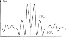
ここで、この発明による検出側における措置を更に説明するために、図2aと2bを参照されたい。この場合、図2aは、インクリメンタル走査信号INCと関連させて、基準インパルス信号検出器ユニット24aの一部を模式化した平面図を示しており、図2bでは、このような実施形態に対応する、図2aのバンドパスフィルターとして作用する基準インパルス信号検出器ユニットのフィルター関数F(k)を図示している。 Reference is now made to FIGS. 2a and 2b to further explain the measures on the detection side according to the invention. In this case, FIG. 2a shows a plan view schematically illustrating a part of the reference impulse signal detector unit 24a in connection with the incremental scanning signal INC, and FIG. 2b corresponds to such an embodiment. Fig. 2b illustrates the filter function F (k) of the reference impulse signal detector unit acting as the bandpass filter of Fig. 2a.
既に前述した通り、この発明では、基準インパルス信号検出器ユニットの構成は、このユニットが、検出面に生じる基準位置xREF で振幅変調された縞模様に対してバンドパスフィルターとして作用し、そのようにして所望の幅の基準インパルス信号RIを生成するものと規定される。基準インパルス信号検出器ユニットのバンドパスフィルターとしての作用の結果、走査したインクリメンタル目盛の基本周波数fINC が、そのより高い高調波を含めて、その他の単に比較的ゆっくりと変化する信号成分と同様に、検出面での振幅変調された走査信号から除去されることとなる。それに対して、インクリメンタル信号の基本周波数の約半分の周波数fINC /2の周りの所定の間隔の周波数を持つ信号成分は、所望の幅を持つ基準インパルス信号RIを生成するために、大幅に弱められることなく集積される。こうすることによって、検出した走査信号から、基準インパルス信号RIを生成するのに適した周波数帯域だけが、フィルターにより取り出される。 As already mentioned above, in the present invention, the configuration of the reference impulse signal detector unit is such that this unit acts as a bandpass filter against the stripe pattern amplitude-modulated at the reference position x REF that occurs on the detection surface. Thus, it is defined that the reference impulse signal RI having a desired width is generated. As a result of the action of the reference impulse signal detector unit as a bandpass filter, the fundamental frequency f INC of the scanned incremental scale, including its higher harmonics, as well as other relatively slowly changing signal components Then, it is removed from the amplitude-modulated scanning signal on the detection surface. On the other hand, a signal component having a frequency of a predetermined interval around the frequency f INC / 2 which is about half of the fundamental frequency of the incremental signal is significantly weakened in order to generate the reference impulse signal RI having a desired width. It is accumulated without being done. By doing so, only the frequency band suitable for generating the reference impulse signal RI is extracted from the detected scanning signal by the filter.
図1の例の第二の基準インパルス信号検出器ユニット24bは、図2aの基準インパルス信号検出器ユニット24aと基本的に同じである。これらの基準インパルス信号検出器ユニット24a,24bは、図1では、走査板25上の領域240a,240bに配置されている。
The second reference impulse signal detector unit 24b in the example of FIG. 1 is basically the same as the reference impulse signal detector unit 24a of FIG. 2a. These reference impulse signal detector units 24a and 24b are arranged in
以下においては、如何にして、例えば、基準インパルス信号検出器ユニット24aの好適な実施形態によって、基準インパルス信号RIを生成するためのバンドパス機能を実現することができるのかを説明する。図示した実施例では、基準インパルス信号検出器ユニット24aは、三つの個別の基準インパルス信号検出器エレメント26,27.1,27.2から構成されている。基準インパルス信号検出器エレメント26,27.1,27.2の幾何学的なサイズ決定と接続によって、基本的には基準位置xREF における振幅変調された縞模様又は対応する走査信号の目標とするバンドパスフィルター機能が実現され、そのようにして出力側に所望の基準インパルス信号RIが生成される。この例では、そのために、中央の基準インパルス信号検出器エレメント26とこのエレメントに対して対称的に配置された基準インパルス信号検出器エレメント27.1,27.2が配備されている。この場合、このフィルター機能のためには、有利には中央に配置された基準インパルス信号検出器エレメント26の幅b1 が、生成されるインクリメンタル信号INCの信号周期SPINC と同じになるように選定される。
In the following, it will be described how a bandpass function for generating the reference impulse signal RI can be realized, for example, by means of a preferred embodiment of the reference impulse signal detector unit 24a. In the illustrated embodiment, the reference impulse signal detector unit 24a is comprised of three individual reference impulse
このようにして、検出面の縞模様の走査の際に、信号周期SPINC に渡っての正弦波状のインクリメンタル信号INCの平均化とそれによって周期的なインクリメンタル信号成分に関する所望のフィルター効果が得られる。二つの対称的に配置された基準インパルス信号検出器エレメント27.1,27.2の幅b2 は、一方では同じとなるように、他方では中央の基準インパルス信号検出器エレメント26の幅b1 の半分に等しく、即ち、b2 =1/2*b1 となるように選定される。
In this way, when scanning the detection surface with a striped pattern, averaging of the sinusoidal incremental signal INC over the signal period SP INC and thereby the desired filter effect on the periodic incremental signal component is obtained. . The width b 2 of the two symmetrically arranged reference impulse signal detector elements 27.1, 27.2 is on the one hand the same, the width b 1 of the central reference impulse
一般的に、バンドパスフィルターの通過特性は、周知の方式により、そのフィルター関数F(k)によって記述することができ、この場合各信号の通過する周波数成分は、kで表示されている。図2aの基準インパルス信号検出器ユニット24aの実施例では、そこを通過する空間周波数成分kの分布に関して、それに対応するフィルター関数F(k)は、以下の関係式(GI.1)で記述することができる。 In general, the pass characteristic of a band pass filter can be described by its filter function F (k) in a well-known manner. In this case, the frequency component that each signal passes is represented by k. In the embodiment of the reference impulse signal detector unit 24a of FIG. 2a, for the distribution of the spatial frequency component k passing therethrough, the corresponding filter function F (k) is described by the following relational expression (GI.1): be able to.
![]()
k :空間周波数
b1 :中央の基準インパルス信号検出器エレメントの幅
b2 :二つの外側の基準インパルス信号検出器エレメントの中の一方の幅
d :外側の基準インパルス信号検出器エレメントと中央の基準インパルス信号検出器エ レメントとの間隔
η :二つの外側の基準インパルス信号検出器エレメントと中央の基準インパルス信号検 出器エレメントの間の相対的な重み付け又は面積比
図2bには、図2aの基準インパルス信号検出器ユニット24aにおける以下のパラメータの組み合わせに対するフィルター関数F(k)の推移が図示されている。
b1 =35μm、b2 =35μm、η=1、d=48.75μm
図2bでは、インクリメンタル信号の基本周波数fINC =1/SPINC 及びその高調波、例えば2/SPINC などにおいて、フィルター関数F(k)の推移が零となっていることが明らかに分かる。それに対して、前述した通り、インクリメンタル信号の基本周波数fINC の半分の領域における通過周波数帯域が、通過されており、基準インパルス信号として使用される。
![]()
k: spatial frequency b 1 : width of central reference impulse signal detector element b 2 : width of one of the two outer reference impulse signal detector elements d: outer reference impulse signal detector element and central reference Distance η between impulse signal detector elements: relative weighting or area ratio between the two outer reference impulse signal detector elements and the central reference impulse signal detector element. FIG. 2b shows the reference of FIG. The transition of the filter function F (k) for the following combinations of parameters in the impulse signal detector unit 24a is illustrated.
b 1 = 35 μm, b 2 = 35 μm, η = 1, d = 48.75 μm
In FIG. 2b, it can be clearly seen that the transition of the filter function F (k) is zero at the fundamental frequency f INC of the incremental signal = 1 / SP INC and its harmonics, for example 2 / SP INC . On the other hand, as described above, the pass frequency band in the region of half of the fundamental frequency f INC of the incremental signal is passed and used as the reference impulse signal.
この場合、前述した通り、結果として得られる基準インパルス信号からインクリメンタル信号の基本周波数fINC =1/SPINC と場合によってはその高調波をフィルターで排除する基準インパルス信号検出器ユニットを構成するために、式GI.1から、中央の基準インパルス信号検出器エレメントと外側の基準インパルス信号検出器エレメントとの間隔dに関して、基準インパルス信号検出器ユニットの自由に選定可能なパラメータb1 ,b2 ,ηに依存して、式GI.2の形の条件を提示することができる。 In this case, as described above, in order to construct a reference impulse signal detector unit that filters out the harmonics from the resulting reference impulse signal with the fundamental frequency f INC = 1 / SP INC of the incremental signal. Formula GI. 1 to the distance d between the central reference impulse detector element and the outer reference impulse signal detector element, depending on the freely selectable parameters b 1 , b 2 , η of the reference impulse signal detector unit Formula GI. Two forms of conditions can be presented.

z :整数
SPINC :インクリメンタル信号の信号周期
b1 :中央の基準インパルス信号検出器エレメントの幅
b2 :二つの外側の基準インパルス信号検出器エレメントの中の一方の幅
数学的な解が存在するb1 ,b2 ,ηの値の各組み合わせに関して、式GI.2は、インクリメンタル信号の基本周波数をフィルターで排除した形で基本インパルス信号を生成する、基準インパルス信号検出器ユニットの実施形態を提供する。以下において説明する通り、検出器配列の特に有利な実施構成に関して、式GI.2は簡単化される。
z: integer SP INC : signal period of the incremental signal b 1 : width of the center reference impulse signal detector element b 2 : width of one of the two outer reference impulse signal detector elements
For each combination of b 1 , b 2 , η values for which a mathematical solution exists, the equation GI. 2 provides an embodiment of a reference impulse signal detector unit that generates a basic impulse signal in which the fundamental frequency of the incremental signal is filtered out. As described below, for a particularly advantageous implementation of the detector arrangement, the formula GI. 2 is simplified.
図2aに図示した例では、二つの外側の基準インパルス信号検出器エレメント27.1,27.2は、それらによって中央の基準インパルス信号検出器エレメント26の走査信号に対して、一般的な形でN*360°(N=1,2,3....)の位相のずれた走査信号が生成されるように、中央の基準インパルス信号検出器エレメントに対して配置されている。図2aの例では、二つの基準インパルス信号検出器エレメント27.1,27.2に対して、N=1で、かつ幅の関係式b2 =1/2*b1 が選定されている。この配置に関して、中央の基準インパルス信号検出器エレメント26の中心と二つの外側の基準インパルス信号検出器エレメント27.1又は27.2との間の間隔dの選定に関して、式GI.2から、簡単化された関係式GI.3.1又はGI.3.2が得られる。
d=n*SPINC +0.5b2 (GI.3.1)
d=n*SPINC −0.5b2 (GI.3.2)
ここで、
SPINC :インクリメンタル信号の信号周期
b2 :二つの外側の基準インパルス信号検出器エレメントの中の一方の幅
n=0,1,2,3,......
図2aの例では、更に、基準インパルス信号RIを生成するために、一方において二つの外側の基準インパルス信号検出器エレメント27.1,27.2を互いに接続して信号S2とし、更にこの信号S2を中央の基準インパルス信号検出器エレメント26から得られた信号S1と差分を取る形で接続するものと規定する。最終的には、信号S1とS2の差分を取る形の接続により得られる信号は、出力側に生じる基準インパルス信号RIである。
In the example illustrated in FIG. 2a, the two outer reference impulse signal detector elements 27.1, 27.2 are in a general manner relative to the scanning signal of the central reference impulse
d = n * SP INC + 0.5b 2 (GI.3.1)
d = n * SP INC −0.5b 2 (GI.3.2)
here,
SP INC : Incremental signal period b 2 : One of the two outer reference impulse signal detector elements n = 0, 1, 2, 3, ...
In the example of FIG. 2a, in order to generate a reference impulse signal RI, on the one hand, two outer reference impulse signal detector elements 27.1, 27.2 are connected together to form a signal S2, and this signal S2 Is connected to the signal S1 obtained from the central reference impulse
このように幾何学的なサイズと接続を選定した形の基準インパルス信号検出器エレメント26,27.1,27.2の実施形態によって、専ら基準インパルス信号検出器エレメント26,27.1,27.2のバンドパスフィルターとしての設計が実現される。このバンドパスフィルターによって、インクリメンタル目盛トラック11に統合された基準指標REFによって強く乱された、検出面に生じる縞模様から、本来の基準インパルス信号RIに対応する周波数帯域が、フィルターにより取り出される。
The embodiment of the reference impulse
ここで、その次の図面にもとづき、この発明による位置測定装置における送信目盛、基準尺、基準インパルス信号検出器エレメントの構成に関する別の実施例及び結果として得られる信号の推移について説明する。 Here, based on the next drawing, another embodiment relating to the configuration of the transmission scale, the reference scale, and the reference impulse signal detector element in the position measuring device according to the present invention and the transition of the resulting signal will be described.
この場合、図3aは、この発明による位置測定装置の別の実施構成の送信目盛122を図示しており、図3bでは、基準指標REFを含むインクリメンタル目盛トラック111を有する、走査される基準尺100の一部を図示している。
In this case, FIG. 3a illustrates a
この位置測定装置の実施例も、又もや反射光式システムとして構成されている、即ち、測定方向xに対して交番する形で配置されたインクリメンタル目盛トラック111の部分領域が、異なる光学的な反射特性を有する。図3bで明るく図示した部分領域は、大きく反射する形に構成された部分領域又は明視野であり、暗く図示した部分領域は、小さく反射する暗視野を示す。基準位置xREF の基準指標REFは、この位置に明視野を追加することによって形成されており、それによってインクリメンタル目盛トラック111の周期性が乱されている。この例では、インクリメンタル目盛トラック111の周期TPM は、TPM =20μmとして選定されており、一つの部分領域の幅は、10μmである。この例では、基準尺100における基準指標REF又は明視野は、30μmの幅を有し、これは、インクリメンタル目盛トラック111の周期TPM の1.5倍に相当する。このような幅に選定することは、それよってインクリメンタル目盛トラックの周期が出来る限り小さく乱されることとなるので、有利であることが分かっている。
This embodiment of the position measuring device is also configured as a reflected light system, that is, the partial areas of the incremental graduation tracks 111 arranged in an alternating manner with respect to the measuring direction x have different optical reflection characteristics. Have The partial area illustrated brightly in FIG. 3b is a partial area or bright field configured to be highly reflective, and the partial area illustrated darkly represents a dark field that is reflected small. The reference index REF at the reference position x REF is formed by adding a bright field at this position, and thereby the periodicity of the
これに代わって、明視野を幅40μmで構成することもでき、従って、その幅は、インクリメンタル目盛トラックの目盛周期の二倍に相当する。この場合、インクリメンタル目盛トラック111における基準指標REFの明視野は、基準尺上で測定方向xに対して最も近くに隣接する反射率の高い目盛領域又は明視野(透過光式の場合には、透過率の高い目盛領域)との間隔が最大の幅を取り、その際省かれる反射率の高い又は透過率の高い目盛領域の数が出来る限り最少に選定されるように配置するのが有利であることが分かっている。有利には、明視野と基準尺上で測定方向xに対して最も近くに隣接する反射率の高い目盛領域との間隔は、インクリメンタル目盛トラック111の目盛周期の1.5倍である。
Alternatively, the bright field can be configured with a width of 40 μm, and therefore the width corresponds to twice the scale period of the incremental scale track. In this case, the bright field of the reference index REF in the
図3aでは、送信目盛122の側には、交番する形で配置された透過率が異なる部分領域で構成された、測定方向xに対してほぼ周期的な構造が配備されている。図3aで明るく図示した部分領域は、光学的に透過性を持つ形で構成されており、暗く図示した部分領域は、光学的に透過性を持たない形で構成されている。この例では、送信目盛122の周期TPS は、TPS =40μmであり、送信目盛122の部分領域の幅は、20μmに相当する。この例では、送信目盛122の側には、基準尺100上の基準指標REFの実施形態に合わせて、中央の領域に、一つの透明な部分領域が省かれている、即ち、目盛構造の非周期性が、中央に配置された幅60μmの暗視野の形で実現されており、この幅は、送信目盛122の周期TPS の約1.5倍に相当する。このように暗視野の幅を選定することは、そのようにして、さもなければ周期的であった送信目盛122を最小限に変更することとなるので、有利であることが分かっている。
In FIG. 3a, on the
基本的には、送信目盛122の非周期性又は暗視野を、図3cに代わって、分散した形で配置することもでき、暗視野の実現可能な幅は、40μm〜80μmの範囲で選定することができる。
Basically, the non-periodicity or dark field of the
図3cでは、対応する基準インパルス信号検出器ユニット124aが模式的に図示されており、この場合、その実施形態は、基本的には図2で説明した実施例の形態に相当する。基準インパルス信号検出器ユニット124aは、又もや幅b1 =35μmの一つの中央に配置された基準インパルス信号検出器エレメント126とそれぞれ幅b2 =17.5μmの二つの外側の基準インパルス信号検出器エレメント127.1,127.2とを有する。図示されていない走査板の面には、中央の基準インパルス信号検出器エレメント126が、基準尺の明視野又は基準指標REFの中央に延びる位置に配置されている。また、前の例と同様に、基準インパルス信号RIを生成するために、これらの異なる基準インパルス信号検出器エレメント126,127.1,127.2を接続することも行っている。
In FIG. 3c, a corresponding reference impulse
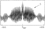
図3aと3bの基準尺100と送信目盛122を持つシステムに関して、基準位置xREF の周りの+/−4mmの範囲における走査ユニットの検出面の縞模様の走査により得られる全体的な走査信号Sが、図4aに図示されている。この場合、この図では、高い解像度で位置を求めるのに有用である高い周波数のインクリメンタル信号成分が明らかに分かる。この信号成分には、この範囲においてインクリメンタル目盛トラック111の周期性が乱されたことに起因する明らかに低い周波数の信号成分が重畳されている、或いは基準位置xREF の領域において、振幅に関して大きな影響が与えられている。この例の通り、送信目盛112が、中央の領域に、さもなければ周期的であった送信目盛の非周期なものとしての暗視野を有する場合、図4aの全体的な走査信号Sにおいて、基準位置xREF の領域には、この信号の包絡線に関する信号の急低下が生じる。
For the system with the
ここで、この全体的な走査信号Sにおける信号の急低下は、基準インパルス信号検出器ユニット124aの前述した実施形態によって、出力側で使用可能な高い解像度の基準インパルス信号RIに変換することができる。図4bには、一方における中央の基準インパルス信号検出器エレメント126の信号S1と他方における対称的に配置された基準インパルス信号検出器エレメント127.1,127.2から得られる信号S2が、基準位置xREF の周りの+/−0.04mmの範囲で図示されている。図4bから分かる通り、両方の信号S1,S2は、それらの振幅の推移において、依然として、インクリメンタル目盛トラック111の影響に起因する重畳した周期性を有する。最後に、図4cには、S1とS2の差分を取ることにより得られる基準インパルス信号RIが図示されており、この信号は、基準位置xREF の周りの+/−0.04mmの範囲において、明らかな信号の急低下を有する。S1とS2の差分を取ることから、インクリメンタル信号の周期的な成分が、基準インパルス信号RIにおいて、フィルターにより取り出される。後続の電子機器によって周知の方式で再処理可能である、位置に依存した高い解像度の基準インパルス信号RIが得られる。この発明による基準インパルス信号検出器ユニット124aの実施形態によって、図4aに図示した全体的な走査信号Sから、高い解像度の基準インパルス信号RIが、フィルターで取り出される。
Here, the sudden drop of the signal in the overall scanning signal S can be converted into a high-resolution reference impulse signal RI that can be used on the output side by the above-described embodiment of the reference impulse
送信目盛、基準尺、対応する基準インパルス信号検出器ユニットの構成に関する別の実施例及び様々な信号の推移が、前の例と同様に、図5a〜5cと図6a〜6cに図示されている。これらの図面の以下における記述では、前の例との重要な相違点だけを説明する。 Another embodiment of the transmission scale, reference scale, corresponding reference impulse signal detector unit configuration and various signal transitions are illustrated in FIGS. 5a-5c and 6a-6c, as in the previous example. . In the following description of these drawings, only significant differences from the previous example will be described.
この場合、インクリメンタル目盛トラック211と基準指標を持つ基準尺200の構成が、前の例と同様に選定されている一方、図5aに図示されている通り、使用されている送信目盛222が、前の例とは異なっている。即ち、ここでは、送信目盛222の中央の領域において、測定方向xに対して幅を広げた60μmの幅の明視野を形成するものと規定する。この目盛構造の中の少なくとも一つの非透過性の部分領域を省くことによって、このことを実現している。この送信目盛の好適な明視野の幅は、36μm〜110μmの範囲に選定することができる。送信目盛222の周期TPS は、前の例の通り、TPS =40μmであり、測定方向における部分領域の幅は、20μmである。
In this case, the configuration of the
基準尺200と基準インパルス信号検出器ユニット224aは、前の例と同様に構成されている。
The
ここで、図6aから明らかな通り、送信目盛222の実施形態が異なるために、基準位置xREF において、全体的な走査信号Sの包絡線に関する信号の最大値が生じており、前の例では、この位置において、信号の急低下が生じていた。
Here, as is clear from FIG. 6a, because the embodiment of the
同様に、このことは、図6bと6cに図示されている通り、信号S1とS2及び結果として得られる基準インパルス信号RIにおいても現れている。即ち、この例では、基準位置xREF が、基準インパルス信号RIにおいて、明らかな信号の上昇として特徴付けられている。しかし、前の例と同様に、図6cからは、又もや、この発明による検出器側での措置によって、基準インパルス信号RIにおける周期的なインクリメンタル信号成分のフィルタリングが行われているのが分かる。 Similarly, this also appears in the signals S1 and S2 and the resulting reference impulse signal RI, as illustrated in FIGS. 6b and 6c. That is, in this example, the reference position x REF is characterized as a clear signal rise in the reference impulse signal RI. However, as in the previous example, it can be seen from FIG. 6c that filtering of the incremental incremental signal component in the reference impulse signal RI is again performed by the measure on the detector side according to the present invention.
以下において、図7a〜7cと図8a〜8cにもとづき、この発明による基準インパルス信号を生成するための別の変化形態を説明する。基準インパルス信号を生成するために重要である、位置測定装置の様々な部品の図面及び様々な信号の図面は、又もや前の二つの例の図面に対応している。そのため、以下においては、基本的にこの実施構成の相違点だけを説明する。 In the following, another variant for generating a reference impulse signal according to the invention will be described on the basis of FIGS. 7a to 7c and FIGS. 8a to 8c. The drawings of the various parts of the position-measuring device and the drawings of the various signals that are important for generating the reference impulse signal again correspond to the drawings of the two previous examples. Therefore, in the following, only the differences of this embodiment will be basically described.
この例では、図7bの基準尺の図面から明らかな通り、基準尺300のインクリメンタル目盛トラック311には、もはや単一の明視野だけではなく、そのような多くの明視野が、基準指標REFとして統合されていることが重要である。全体として、この実施例の基準指標は、測定方向xに対して広がった全部で14個の明視野又は大きく反射する部分領域の分布を有し、これらの部分領域は、それぞれ前述した通り、インクリメンタル目盛トラック311の一つの反射しない部分領域を省くことから得られる。各個別の明視野は、前述した通り、測定方向xに対して30μm又は40μmの幅を有し、インクリメンタル目盛トラック311は、前の例と同様に、部分領域の幅が10μmで、周期又は目盛周期TPM =20μmを有する。
In this example, as is clear from the reference scale drawing of FIG. 7b, the
又もや図7aで図示した、この実施例の送信目盛322は、図3aの実施例と同様に構成されている。このことは、この目盛が、中央に配置された暗視野の形式の非周期性を有することを意味する。その他の点については、この目盛の前に挙げたデータを参照されたい。
Again, the
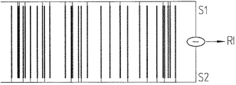
ここで、この例では、検出側は、既に規定された基準尺300の基準指標REFの多数の明視野に対応する形で構成されており、この検出側については、図7cにもとづき説明する。即ち、基準インパルス信号を生成するために、全部で14個のユニットの個別の基準インパルス信号検出器ユニットを配備しており、前の例では、これらのユニットは、インクリメンタル目盛トラックにおける一つの個別の明視野を検出するために必要であった。この場合、各個別の基準インパルス信号検出器ユニットは、前の例の個別のユニットと同じであり、一つの中央の基準インパルス信号検出器エレメントとこのエレメントに対して対称的に配置された二つの基準インパルス信号検出器エレメントから構成されている。図7cから明らかな通り、縞模様の走査から得られた中央の基準インパルス信号検出器エレメントの信号が、信号S1に、各外側に置かれた基準インパルス信号検出器エレメントの信号が信号S2に纏められている。信号S1とS2は、又もや差分を取る形で接続されており、その差分信号として、基準インパルス信号RIが得られる。
Here, in this example, the detection side is configured to correspond to a number of bright fields of the reference index REF of the
図8aには、前の例と同様に、走査から得られた全体的な信号Sが、基準位置xREF の周りの+/−4mmの範囲において図示されており、図8bには、多数の検出器エレメントユニットの信号S1,S2が、基準位置xREF の周りの+/−0.2mmの範囲において図示されている。最後に、図8cは、結果として得られた差分信号又は出力側の基準インパルス信号RIを図示しており、この信号では、この発明による措置により、明らかな影響の低減が見られる。 In FIG. 8a, as in the previous example, the overall signal S obtained from the scan is shown in the range of +/− 4 mm around the reference position x REF , and in FIG. The detector element unit signals S1, S2 are shown in the range of +/− 0.2 mm around the reference position x REF . Finally, FIG. 8c illustrates the resulting difference signal or output-side reference impulse signal RI, in which a clear reduction of the effect is seen by the measures according to the invention.
このような複数の基準インパルス信号検出器ユニットによる実施形態を選定した場合、これらのユニットは、図7cから明らかな通り、測定方向xに対して、所定の範囲に渡って分散した形で配置される。この場合、隣接する基準インパルス信号検出器ユニットの間には、部分的に未だ利用可能な場所が、隙間領域の形で存在する。これらの隙間領域は、例えば、そこに更に追加のインクリメンタル信号検出器エレメントを配置して利用することもできる。 If an embodiment with such a plurality of reference impulse signal detector units is selected, these units are arranged in a distributed manner over a predetermined range with respect to the measuring direction x, as is apparent from FIG. 7c. The In this case, a portion that is still available between adjacent reference impulse signal detector units exists in the form of a gap region. These gap regions can also be used, for example, by arranging additional incremental signal detector elements there.
基準指標に多数の明視野を配備する、この変化形態は、生成する基準インパルス信号の効率又は有効な成分を増大させるのに有利である。 This variation of deploying a large number of bright fields in the reference index is advantageous for increasing the efficiency or effective component of the generated reference impulse signal.
次に、基準尺上の対応する構造と送信格子を含む好適な基準インパルス信号検出器ユニットに関する実現可能な別の実施構成を、続く図9a〜9cと図10a〜10cにもとづき説明する。 Next, another possible implementation of a suitable reference impulse signal detector unit including a corresponding structure on the reference scale and a transmission grating will be described on the basis of the subsequent FIGS. 9a to 9c and FIGS. 10a to 10c.
図9a〜9cの実施例において、図9bは、又もや基準尺400上の走査されるインクリメンタル目盛トラック411の一部を図示している。基準指標REFは、二つの明視野によって、即ち、反射光式走査の場合には反射率の高い、透過光式走査の場合には透過率が高い部分領域によって構成されている。図9aに図示した送信目盛422は、前の例と同様に構成されている。
In the embodiment of FIGS. 9 a-9 c, FIG. 9 b again shows a portion of the
この基準指標REFを走査するのに好適な基準インパルス信号検出器ユニット424aが、図9cに図示されている。このユニットは、二対の基準インパルス信号検出器エレメント426.1,426.2と427.1,427.2から構成されている。基準インパルス信号検出器エレメント426.1,426.2,427.1,427.2の間隔は、各対内ではそれぞれSPINC であり、そのためインクリメンタル信号の信号周期又は検出面の対応する縞模様周期に相当する。一つの対の中の二つの基準インパルス信号検出器エレメント426.1,426.2又は427.1,427.2は、逆相又は180°位相のずれた走査信号S1とS2を提供し、これらの信号は、前の例の通り差分を取る形で接続されており、その結果出力側には、基準インパルス信号RIが得られる。更に、位相の異なる走査信号S1,S2を提供する個別の基準インパルス信号検出器エレメントの順序が、測定方向xに対して、隣接する対から隣接する対へと変更されている、或いは逆になっていることにも言及したい。即ち、図において、左から見て、先ずは信号S1を提供する基準インパルス信号検出器エレメント426.2が配置されており、そして、この対の中の信号S2を生成する基準インパルス信号検出器エレメント426.1が続いている。この直ぐ隣の基準インパルス信号検出器エレメントの対では、それと全く逆であり、先ずはその中の信号S2を提供する基準インパルス信号検出器エレメント427.1が配置されており、そして、ようやく信号S1を生成するための基準インパルス信号検出器エレメント427.2が続いている等々。このようにして、基準インパルス信号検出器エレメントの全体的な配列に渡って、走査信号において誤差を平均化させることとなる対称性が得られる。 A reference impulse signal detector unit 424a suitable for scanning this reference index REF is shown in FIG. 9c. This unit consists of two pairs of reference impulse signal detector elements 426.1, 426.2 and 427.1, 427.2. The interval between the reference impulse signal detector elements 426.1, 426.2, 427.1, 427.2 is SP INC within each pair, so that the signal period of the incremental signal or the corresponding fringe pattern period of the detection surface. Equivalent to. Two reference impulse signal detector elements 426.1, 426.2 or 427.1, 427.2 in one pair provide scan signals S1 and S2 that are out of phase or 180 ° out of phase, and Are connected in such a manner as to take a difference as in the previous example, and as a result, a reference impulse signal RI is obtained on the output side. Furthermore, the order of the individual reference impulse signal detector elements providing the scanning signals S1, S2 with different phases has been changed from an adjacent pair to an adjacent pair or reversed with respect to the measuring direction x. I want to mention that That is, as viewed from the left in the figure, a reference impulse signal detector element 426.2 that first provides a signal S1 is arranged, and a reference impulse signal detector element that generates the signal S2 in this pair. 426.1 follows. In this immediately adjacent pair of reference impulse signal detector elements, the opposite is true, first a reference impulse signal detector element 427.1 providing the signal S2 therein is arranged, and finally the signal S1 Followed by a reference impulse signal detector element 427.2, etc. In this way, symmetry is obtained that will average out the errors in the scan signal over the entire array of reference impulse signal detector elements.
更に、この変化形態は、図7a〜7cの例と同様に、このような多数の明視野をインクリメンタル目盛トラックに配備した実施構成に構成することができる。送信目盛422、インクリメンタル目盛トラック511に基準指標REFを統合した基準尺500、対応する検出器配列の図面が、図10a〜10cに図示されている。この実施形態を前の例に対して補足するものとして、隣接する対における基準インパルス信号検出器エレメントの順序が交番している点だけを再度指摘しておきたい。即ち、左から見て一番目の対の基準インパルス信号検出器エレメントは、S2とS1の信号を、その次の対は、S1とS2の信号等々を提供している。この例においても、この配列によって、検出器配列の全体的な対称性が保証されている。
Furthermore, this variation can be configured in an implementation in which a large number of such bright fields are provided on an incremental graduation track, similar to the example of FIGS. Drawings of the
当然のことながら、この発明の範囲内において、これらの説明した実施例以外にも、代替となる実施構成が存在するものである。 Naturally, within the scope of the present invention, there are alternative implementations in addition to these described embodiments.
10,100,200,300,400,500 基準尺
11,111,211,311,411,511 インクリメンタル目盛トラック
12a,12b 目盛領域
22,122,222,322,422 送信目盛
24a,124a,224a,324a 基準インパルス信号検出器ユニット
26,27.1,27.2,126,127.1,127.2,226,227.1,227.2,426.1,426.2,427.1,427.2 基準インパルス信号検出器エレメント
13 走査面
20 走査ユニット
21 光源
230a,230b,240a,240b 走査板25の領域
25 走査板
b1 中央の基準インパルス信号検出器エレメントの幅
b2 外側の基準インパルス信号検出器エレメントの幅
d 中央の基準インパルス信号検出器エレメントと外側の基準インパルス信 号検出器エレメントとの間隔
F(k) フィルター関数
k 空間周波数
S 全体的な走査信号
S1,S2 走査信号
SPINC インクリメンタル信号の信号周期
RI 基準インパルス信号
REF 基準指標
TPM インクリメンタル目盛トラックの目盛周期
x 測定方向
xREF 基準位置
10, 100, 200, 300, 400, 500
Claims (11)
基準尺(10)は、少なくとも一つのインクリメンタル目盛トラック(11;111;211;311)を有し、この目盛トラックは、測定方向(x)に延びており、基本的に光学特性が異なる目盛領域(12a,12b)の周期的な配列で構成されており、少なくとも一つの基準位置(xREF)に、目盛領域(12a,12b)の非周期的な配列で構成される基準指標(REF)を有し、
走査ユニット(20)は、コリメーターレンズを前置していない光源(21)と光電式検出器配列を有し、この検出器配列は、少なくとも一つの基準インパルス信号検出器ユニット(24a,24b;124a;224a;324a)を有し、この検出器ユニットは、基準指標(REF)と対応して基準インパルス信号(RI)を生成し、
基準位置(xREF)の領域で振幅変調された周期的な縞模様が、検出面に生じる、
位置測定装置において、
基準インパルス信号検出器ユニット(24a,24b;124a;224a;324a)は、複数の基準インパルス信号検出器エレメント(26,27.1,27.2;126,127.1,127.2;226,227.1,227.2)から構成されており、これらの検出器エレメントは、これらの検出器エレメントが、基準位置(xREF)で振幅変調された縞模様に対してバンドパスフィルターとして作用するとともに、出力側において、インクリメンタル目盛トラック(11;111;211;311)からの周期的な信号成分と低周波の信号成分をフィルターで除去した基準インパルス信号(RI)が生じるように、サイズを規定されるとともに、基準インパルス信号(RI)を生成するように接続されていることと、
基準インパルス信号検出器ユニット(24a,24b;124a;224a;324a)は、一つの中央に配置された基準インパルス信号検出器エレメント(26;126;226)とこのエレメントに対して測定方向(x)に対称的に配置された二つの基準インパルス信号検出器エレメント(27.1,27.2;127.1,127.2;227.1,227.2)とを有し、これらの二つの検出器エレメントは、この中央の基準インパルス信号検出器エレメント(26;126;226)に対してN*360°(N=1,2,...)の位相のずれた走査信号を生成するとともに、一方における中央に配置された基準インパルス信号検出器エレメント(26;126;226)と他方におけるこのエレメントに対して測定方向(x)に対称的に配置された二つの基準インパルス信号検出器エレメント(27.1,27.2;127.1,127.2;227.1,227.2)が、差分を取る形で接続されており、この差分信号が、基準インパルス信号(RI)となることと、
中央に配置された基準インパルス信号検出器エレメント(26;126;226)の幅(b 1 )が、このエレメントに対して測定方向(x)に対称的に配置された二つの基準インパルス信号検出器エレメント(27.1,27.2;127.1,127.2;227.1,227.2)の幅(b 2 )の二倍の大きさとなるように選定することと、
を特徴とする位置測定装置。 A position measuring device for generating a position-dependent scanning signal comprising a reference scale (10) and a scanning unit (20) arranged so as to move relative to each other in the measuring direction (x). In this case, the reference scale (10) has at least one incremental scale track (11; 111; 211; 311), and this scale track extends in the measuring direction (x) and basically has optical characteristics. Is composed of a periodic array of different scale areas (12a, 12b), and a reference index composed of an aperiodic array of scale areas (12a, 12b) at at least one reference position (x REF ) (REF)
The scanning unit (20) has a light source (21) without a collimator lens and a photoelectric detector array, which detector array comprises at least one reference impulse signal detector unit (24a, 24b; 124a; 224a; 324a), this detector unit generates a reference impulse signal (RI) corresponding to the reference index (REF),
A periodic stripe pattern amplitude-modulated in the region of the reference position (x REF ) is generated on the detection surface.
In the position measuring device,
The reference impulse signal detector unit (24a, 24b; 124a; 224a; 324a) includes a plurality of reference impulse signal detector elements (26, 27.1, 27.2; 126, 127.1, 127.2; 226). 227.1, 227.2), and these detector elements act as bandpass filters on the stripe pattern where these detector elements are amplitude modulated at the reference position (x REF ). At the same time, on the output side, the size is defined so that a reference impulse signal (RI) is generated by removing the periodic signal component from the incremental scale track (11; 111; 211; 311) and the low-frequency signal component by a filter. And connected to generate a reference impulse signal (RI) ;
The reference impulse signal detector unit (24a, 24b; 124a; 224a; 324a) comprises a centrally arranged reference impulse signal detector element (26; 126; 226) and a measuring direction (x) relative to this element. And two reference impulse signal detector elements (27.1, 27.2; 127.1, 127.2; 227.1, 227.2) arranged symmetrically to each other The generator element generates N * 360 ° (N = 1, 2,...) Out-of-phase scan signals relative to this central reference impulse signal detector element (26; 126; 226); A reference impulse signal detector element (26; 126; 226) arranged centrally on one side and in the measuring direction (x) with respect to this element on the other side Two reference impulse signal detector elements (27.1, 27.2; 127.1, 127.2; 227.1, 227.2) arranged in a nominal manner are connected in a differential manner The differential signal becomes a reference impulse signal (RI);
Two reference impulse signal detectors in which the width (b 1 ) of the centrally arranged reference impulse signal detector element (26; 126; 226) is arranged symmetrically in the measuring direction (x) with respect to this element Selecting to be twice the width (b 2 ) of the elements (27.1, 27.2; 127.1, 127.2; 227.1, 227.2);
A position measuring device characterized by the above.
d=n*SPINC+0.5b2
又は
d=n*SPINC−0.5b2
ここで、
SPINC:インクリメンタル信号の信号周期
b2 :外側の基準インパルス信号検出器エレメントの幅
n :0,1,2,3,……
にもとづき選定することを特徴とする請求項1に記載の位置測定装置。 A centrally located reference impulse signal detector element (26; 126; 226) and a reference impulse signal detector element (27.1, 27.2; 127.1, 127.2; 227.1) adjacent to this element. , 227.2) is expressed by the following formula: d = n * SP INC + 0.5b 2
Or d = n * SP INC −0.5b 2
here,
SP INC : Incremental signal signal period b 2 : Outer reference impulse signal detector element width n: 0, 1, 2, 3,...
The position measuring device according to claim 1 , wherein the position measuring device is selected based on the selection.
中央の領域に、送信目盛(22)が配置されており、
送信目盛(22)に隣接して、当該のインクリメンタル信号検出器エレメントが配置されており、
送信目盛(22)には、測定方向(x)に対して垂直に隣接する形で、少なくとも一つの基準インパルス信号検出器ユニット(24a,24b)が配置されている、
ことを特徴とする請求項1から9までのいずれか一つに記載の位置測定装置。 The scanning unit (20) has one scanning plate (25), and in this scanning plate,
A transmission scale (22) is arranged in the central area,
Adjacent to the transmission scale (22), the relevant incremental signal detector element is arranged,
At least one reference impulse signal detector unit (24a, 24b) is arranged on the transmission graduation (22) so as to be perpendicular to the measurement direction (x).
Position measuring device according to any one of claims 1, wherein up to 9 that.
Applications Claiming Priority (2)
| Application Number | Priority Date | Filing Date | Title |
|---|---|---|---|
| DE102005006247.4 | 2005-02-11 | ||
| DE102005006247A DE102005006247A1 (en) | 2005-02-11 | 2005-02-11 | Position measuring device |
Publications (3)
| Publication Number | Publication Date |
|---|---|
| JP2006220655A JP2006220655A (en) | 2006-08-24 |
| JP2006220655A5 JP2006220655A5 (en) | 2008-12-04 |
| JP5046523B2 true JP5046523B2 (en) | 2012-10-10 |
Family
ID=36128274
Family Applications (1)
| Application Number | Title | Priority Date | Filing Date |
|---|---|---|---|
| JP2006031779A Active JP5046523B2 (en) | 2005-02-11 | 2006-02-09 | Position measuring device |
Country Status (5)
| Country | Link |
|---|---|
| US (1) | US7348546B2 (en) |
| EP (1) | EP1691172B1 (en) |
| JP (1) | JP5046523B2 (en) |
| DE (1) | DE102005006247A1 (en) |
| ES (1) | ES2562238T3 (en) |
Families Citing this family (19)
| Publication number | Priority date | Publication date | Assignee | Title |
|---|---|---|---|---|
| DE102006021484A1 (en) * | 2006-05-09 | 2007-11-15 | Dr. Johannes Heidenhain Gmbh | Optical position measuring unit, has scanning unit producing reference signal at reference position, where reference marking possesses middle partition period within region of division period of incremental partitions |
| JP4928206B2 (en) | 2006-09-22 | 2012-05-09 | キヤノン株式会社 | Encoder |
| DE102007035345A1 (en) * | 2006-11-20 | 2008-05-21 | Dr. Johannes Heidenhain Gmbh | Position measuring device |
| DE102007023300A1 (en) * | 2007-05-16 | 2008-11-20 | Dr. Johannes Heidenhain Gmbh | Position measuring device and arrangement thereof |
| US10259607B2 (en) * | 2008-03-04 | 2019-04-16 | Vanrx Pharmasystems Inc. | Aseptic robotic filling system and method |
| JP5113000B2 (en) * | 2008-09-19 | 2013-01-09 | 株式会社ミツトヨ | Photoelectric encoder |
| JP5666126B2 (en) * | 2008-12-23 | 2015-02-12 | アバゴ・テクノロジーズ・ジェネラル・アイピー(シンガポール)プライベート・リミテッド | Single track optical encoder |
| KR20100135048A (en) * | 2009-06-16 | 2010-12-24 | 삼성전자주식회사 | Encoder capable of compensating tilt, hard disk drive using the same, and servo track writing system for the hard disk drive |
| DE102009046773A1 (en) * | 2009-11-17 | 2011-05-19 | Dr. Johannes Heidenhain Gmbh | Scanning unit of a position measuring device |
| JP5391115B2 (en) * | 2010-03-18 | 2014-01-15 | 株式会社ミツトヨ | Photoelectric encoder |
| EP2386832B1 (en) * | 2010-05-10 | 2017-04-12 | Mitutoyo Corporation | Photoelectric encoder |
| US9074911B2 (en) | 2011-08-26 | 2015-07-07 | Nikon Corporation | Measurement system and method utilizing high contrast encoder head for measuring relative movement between objects |
| DE102012221566A1 (en) * | 2012-11-26 | 2014-05-28 | Dr. Johannes Heidenhain Gmbh | Optical position measuring device |
| DE102014215633A1 (en) * | 2013-11-28 | 2015-05-28 | Dr. Johannes Heidenhain Gmbh | Position measuring device |
| JP6359340B2 (en) * | 2014-05-27 | 2018-07-18 | 株式会社ミツトヨ | Scale and optical encoder |
| JP6474289B2 (en) * | 2015-03-19 | 2019-02-27 | 株式会社キーエンス | Optical rotary encoder |
| JP6732487B2 (en) * | 2016-03-17 | 2020-07-29 | 株式会社東京精密 | Encoder having linear scale and origin determination method thereof |
| DE102017201257A1 (en) * | 2017-01-26 | 2018-07-26 | Dr. Johannes Heidenhain Gmbh | Position measuring device |
| EP3623769A1 (en) | 2018-09-12 | 2020-03-18 | Renishaw PLC | Measurement device |
Family Cites Families (13)
| Publication number | Priority date | Publication date | Assignee | Title |
|---|---|---|---|---|
| SE379241B (en) | 1974-01-15 | 1975-09-29 | Aga Ab | |
| DE19726935B4 (en) * | 1997-06-25 | 2014-06-12 | Dr. Johannes Heidenhain Gmbh | Optical position measuring device |
| DE19830925A1 (en) * | 1997-08-07 | 1999-02-11 | Heidenhain Gmbh Dr Johannes | Sensing unit for optical position measurement |
| DE19754595B4 (en) * | 1997-12-10 | 2011-06-01 | Dr. Johannes Heidenhain Gmbh | Photoelectric position measuring device |
| DE19936181A1 (en) * | 1998-11-19 | 2000-05-25 | Heidenhain Gmbh Dr Johannes | Optical position measuring device |
| DE19918101A1 (en) * | 1999-04-22 | 2000-10-26 | Heidenhain Gmbh Dr Johannes | Optical position measurement device, has scanning unit with detector arrangement with blocks of detector elements in measurement direction with period derived from Vernier period |
| DE19941318A1 (en) * | 1999-08-31 | 2001-03-15 | Heidenhain Gmbh Dr Johannes | Optical position measuring device |
| GB0103582D0 (en) | 2001-02-14 | 2001-03-28 | Renishaw Plc | Position determination system |
| JP2005526951A (en) * | 2001-08-30 | 2005-09-08 | ジーエスアイ・ルモニックス・コーポレーション | Reference point Talbot encoder |
| US7002137B2 (en) * | 2001-08-30 | 2006-02-21 | Gsi Lumonics Corporation | Reference point talbot encoder |
| WO2004005855A2 (en) * | 2002-07-08 | 2004-01-15 | Microe Systems Corporation | Multi-track optical encoder employing beam divider |
| US6664535B1 (en) * | 2002-07-16 | 2003-12-16 | Mitutoyo Corporation | Scale structures and methods usable in an absolute position transducer |
| GB0316921D0 (en) * | 2003-07-19 | 2003-08-27 | Renishaw Plc | Reader for a scale marking |
-
2005
- 2005-02-11 DE DE102005006247A patent/DE102005006247A1/en not_active Withdrawn
-
2006
- 2006-02-04 ES ES06002322.3T patent/ES2562238T3/en active Active
- 2006-02-04 EP EP06002322.3A patent/EP1691172B1/en not_active Not-in-force
- 2006-02-09 JP JP2006031779A patent/JP5046523B2/en active Active
- 2006-02-09 US US11/350,460 patent/US7348546B2/en not_active Expired - Fee Related
Also Published As
| Publication number | Publication date |
|---|---|
| ES2562238T3 (en) | 2016-03-03 |
| US20060180748A1 (en) | 2006-08-17 |
| EP1691172A2 (en) | 2006-08-16 |
| EP1691172A3 (en) | 2012-06-20 |
| US7348546B2 (en) | 2008-03-25 |
| EP1691172B1 (en) | 2016-02-03 |
| JP2006220655A (en) | 2006-08-24 |
| DE102005006247A1 (en) | 2006-08-17 |
Similar Documents
| Publication | Publication Date | Title |
|---|---|---|
| JP5046523B2 (en) | Position measuring device | |
| JP4324261B2 (en) | Scanning unit for optical position measuring device | |
| JP5717633B2 (en) | Optical position measuring device | |
| JP4503799B2 (en) | Optical position measuring device | |
| JP4503822B2 (en) | Position measuring device | |
| JP5976279B2 (en) | Optical encoder and position measuring method | |
| JP2006220655A5 (en) | ||
| JP4266834B2 (en) | Optical encoder | |
| EP2023094B1 (en) | Reference signal generating configuration for an interferometric miniature grating encoder readhead using fiber optic receiver channels | |
| ES2376656T3 (en) | POSITION METER DEVICE. | |
| JPH05133769A (en) | Interference-position measuring apparatus | |
| JPH0131127B2 (en) | ||
| US6914235B2 (en) | Position measuring system and method for operating a position measuring system | |
| EP2469241B1 (en) | Optical encoder readhead configuration | |
| JP2018530751A (en) | Encoder device | |
| US20170089737A1 (en) | Optical encoder | |
| JP2818800B2 (en) | Device for generating position-dependent signals | |
| JP4303804B2 (en) | Optical position measuring device | |
| JP6563813B2 (en) | Optical element | |
| US6552810B1 (en) | Optical measuring system | |
| JP5693840B2 (en) | Optical fiber interferometric grating encoder capable of detecting a reference signal | |
| JPH095026A (en) | Photoelectric position measuring device | |
| JPH09113213A (en) | Device for filtering higher-harmonic signal component | |
| JP3881339B2 (en) | Position measuring device | |
| JP2004501356A (en) | Scanning unit for optical position measuring device |
Legal Events
| Date | Code | Title | Description |
|---|---|---|---|
| A521 | Request for written amendment filed |
Free format text: JAPANESE INTERMEDIATE CODE: A523 Effective date: 20081017 |
|
| A621 | Written request for application examination |
Free format text: JAPANESE INTERMEDIATE CODE: A621 Effective date: 20081017 |
|
| RD04 | Notification of resignation of power of attorney |
Free format text: JAPANESE INTERMEDIATE CODE: A7424 Effective date: 20100517 |
|
| A977 | Report on retrieval |
Free format text: JAPANESE INTERMEDIATE CODE: A971007 Effective date: 20110304 |
|
| A131 | Notification of reasons for refusal |
Free format text: JAPANESE INTERMEDIATE CODE: A131 Effective date: 20120110 |
|
| A521 | Request for written amendment filed |
Free format text: JAPANESE INTERMEDIATE CODE: A523 Effective date: 20120402 |
|
| TRDD | Decision of grant or rejection written | ||
| A01 | Written decision to grant a patent or to grant a registration (utility model) |
Free format text: JAPANESE INTERMEDIATE CODE: A01 Effective date: 20120626 |
|
| A01 | Written decision to grant a patent or to grant a registration (utility model) |
Free format text: JAPANESE INTERMEDIATE CODE: A01 |
|
| A61 | First payment of annual fees (during grant procedure) |
Free format text: JAPANESE INTERMEDIATE CODE: A61 Effective date: 20120717 |
|
| FPAY | Renewal fee payment (event date is renewal date of database) |
Free format text: PAYMENT UNTIL: 20150727 Year of fee payment: 3 |
|
| R150 | Certificate of patent or registration of utility model |
Ref document number: 5046523 Country of ref document: JP Free format text: JAPANESE INTERMEDIATE CODE: R150 Free format text: JAPANESE INTERMEDIATE CODE: R150 |
|
| R250 | Receipt of annual fees |
Free format text: JAPANESE INTERMEDIATE CODE: R250 |
|
| R250 | Receipt of annual fees |
Free format text: JAPANESE INTERMEDIATE CODE: R250 |
|
| R250 | Receipt of annual fees |
Free format text: JAPANESE INTERMEDIATE CODE: R250 |
|
| R250 | Receipt of annual fees |
Free format text: JAPANESE INTERMEDIATE CODE: R250 |
|
| R250 | Receipt of annual fees |
Free format text: JAPANESE INTERMEDIATE CODE: R250 |
|
| R250 | Receipt of annual fees |
Free format text: JAPANESE INTERMEDIATE CODE: R250 |
|
| R250 | Receipt of annual fees |
Free format text: JAPANESE INTERMEDIATE CODE: R250 |
|
| R250 | Receipt of annual fees |
Free format text: JAPANESE INTERMEDIATE CODE: R250 |