JP2005526951A - Reference point Talbot encoder - Google Patents
Reference point Talbot encoder Download PDFInfo
- Publication number
- JP2005526951A JP2005526951A JP2003525229A JP2003525229A JP2005526951A JP 2005526951 A JP2005526951 A JP 2005526951A JP 2003525229 A JP2003525229 A JP 2003525229A JP 2003525229 A JP2003525229 A JP 2003525229A JP 2005526951 A JP2005526951 A JP 2005526951A
- Authority
- JP
- Japan
- Prior art keywords
- scale
- sensor head
- detector array
- encoder
- disposed
- Prior art date
- Legal status (The legal status is an assumption and is not a legal conclusion. Google has not performed a legal analysis and makes no representation as to the accuracy of the status listed.)
- Pending
Links
- LFEUVBZXUFMACD-UHFFFAOYSA-H lead(2+);trioxido(oxo)-$l^{5}-arsane Chemical compound [Pb+2].[Pb+2].[Pb+2].[O-][As]([O-])([O-])=O.[O-][As]([O-])([O-])=O LFEUVBZXUFMACD-UHFFFAOYSA-H 0.000 title claims abstract description 26
- 230000003287 optical effect Effects 0.000 claims abstract description 60
- 239000000758 substrate Substances 0.000 claims abstract description 18
- 238000005259 measurement Methods 0.000 claims abstract description 16
- 238000003384 imaging method Methods 0.000 claims abstract description 12
- 238000012545 processing Methods 0.000 claims description 10
- 125000006850 spacer group Chemical group 0.000 claims description 9
- 241000669326 Selenaspidus articulatus Species 0.000 claims 3
- 238000000034 method Methods 0.000 description 16
- 230000008901 benefit Effects 0.000 description 7
- 238000013461 design Methods 0.000 description 5
- 238000006073 displacement reaction Methods 0.000 description 4
- 230000000694 effects Effects 0.000 description 4
- 230000000737 periodic effect Effects 0.000 description 4
- 238000001514 detection method Methods 0.000 description 3
- 239000000463 material Substances 0.000 description 3
- 238000013459 approach Methods 0.000 description 2
- 230000008859 change Effects 0.000 description 2
- 238000004519 manufacturing process Methods 0.000 description 2
- 238000012986 modification Methods 0.000 description 2
- 230000004048 modification Effects 0.000 description 2
- 102000016751 Fringe-like Human genes 0.000 description 1
- 108050006300 Fringe-like Proteins 0.000 description 1
- 230000002745 absorbent Effects 0.000 description 1
- 239000002250 absorbent Substances 0.000 description 1
- 230000002411 adverse Effects 0.000 description 1
- 239000006117 anti-reflective coating Substances 0.000 description 1
- 238000003491 array Methods 0.000 description 1
- 230000015556 catabolic process Effects 0.000 description 1
- 239000003795 chemical substances by application Substances 0.000 description 1
- 239000002131 composite material Substances 0.000 description 1
- 238000006731 degradation reaction Methods 0.000 description 1
- 238000010586 diagram Methods 0.000 description 1
- 238000005530 etching Methods 0.000 description 1
- 239000011521 glass Substances 0.000 description 1
- 238000005286 illumination Methods 0.000 description 1
- 238000003754 machining Methods 0.000 description 1
- 238000012544 monitoring process Methods 0.000 description 1
- 230000010363 phase shift Effects 0.000 description 1
- 238000000206 photolithography Methods 0.000 description 1
- 230000004044 response Effects 0.000 description 1
- 238000000926 separation method Methods 0.000 description 1
- 229910052710 silicon Inorganic materials 0.000 description 1
- 239000010703 silicon Substances 0.000 description 1
- 238000005549 size reduction Methods 0.000 description 1
- 238000012360 testing method Methods 0.000 description 1
Images


Classifications
-
- G—PHYSICS
- G01—MEASURING; TESTING
- G01D—MEASURING NOT SPECIALLY ADAPTED FOR A SPECIFIC VARIABLE; ARRANGEMENTS FOR MEASURING TWO OR MORE VARIABLES NOT COVERED IN A SINGLE OTHER SUBCLASS; TARIFF METERING APPARATUS; MEASURING OR TESTING NOT OTHERWISE PROVIDED FOR
- G01D5/00—Mechanical means for transferring the output of a sensing member; Means for converting the output of a sensing member to another variable where the form or nature of the sensing member does not constrain the means for converting; Transducers not specially adapted for a specific variable
- G01D5/12—Mechanical means for transferring the output of a sensing member; Means for converting the output of a sensing member to another variable where the form or nature of the sensing member does not constrain the means for converting; Transducers not specially adapted for a specific variable using electric or magnetic means
- G01D5/244—Mechanical means for transferring the output of a sensing member; Means for converting the output of a sensing member to another variable where the form or nature of the sensing member does not constrain the means for converting; Transducers not specially adapted for a specific variable using electric or magnetic means influencing characteristics of pulses or pulse trains; generating pulses or pulse trains
- G01D5/245—Mechanical means for transferring the output of a sensing member; Means for converting the output of a sensing member to another variable where the form or nature of the sensing member does not constrain the means for converting; Transducers not specially adapted for a specific variable using electric or magnetic means influencing characteristics of pulses or pulse trains; generating pulses or pulse trains using a variable number of pulses in a train
- G01D5/2454—Encoders incorporating incremental and absolute signals
- G01D5/2455—Encoders incorporating incremental and absolute signals with incremental and absolute tracks on the same encoder
- G01D5/2457—Incremental encoders having reference marks
-
- G—PHYSICS
- G01—MEASURING; TESTING
- G01D—MEASURING NOT SPECIALLY ADAPTED FOR A SPECIFIC VARIABLE; ARRANGEMENTS FOR MEASURING TWO OR MORE VARIABLES NOT COVERED IN A SINGLE OTHER SUBCLASS; TARIFF METERING APPARATUS; MEASURING OR TESTING NOT OTHERWISE PROVIDED FOR
- G01D5/00—Mechanical means for transferring the output of a sensing member; Means for converting the output of a sensing member to another variable where the form or nature of the sensing member does not constrain the means for converting; Transducers not specially adapted for a specific variable
- G01D5/26—Mechanical means for transferring the output of a sensing member; Means for converting the output of a sensing member to another variable where the form or nature of the sensing member does not constrain the means for converting; Transducers not specially adapted for a specific variable characterised by optical transfer means, i.e. using infrared, visible, or ultraviolet light
- G01D5/32—Mechanical means for transferring the output of a sensing member; Means for converting the output of a sensing member to another variable where the form or nature of the sensing member does not constrain the means for converting; Transducers not specially adapted for a specific variable characterised by optical transfer means, i.e. using infrared, visible, or ultraviolet light with attenuation or whole or partial obturation of beams of light
- G01D5/34—Mechanical means for transferring the output of a sensing member; Means for converting the output of a sensing member to another variable where the form or nature of the sensing member does not constrain the means for converting; Transducers not specially adapted for a specific variable characterised by optical transfer means, i.e. using infrared, visible, or ultraviolet light with attenuation or whole or partial obturation of beams of light the beams of light being detected by photocells
- G01D5/36—Forming the light into pulses
- G01D5/366—Particular pulse shapes
-
- G—PHYSICS
- G01—MEASURING; TESTING
- G01D—MEASURING NOT SPECIALLY ADAPTED FOR A SPECIFIC VARIABLE; ARRANGEMENTS FOR MEASURING TWO OR MORE VARIABLES NOT COVERED IN A SINGLE OTHER SUBCLASS; TARIFF METERING APPARATUS; MEASURING OR TESTING NOT OTHERWISE PROVIDED FOR
- G01D5/00—Mechanical means for transferring the output of a sensing member; Means for converting the output of a sensing member to another variable where the form or nature of the sensing member does not constrain the means for converting; Transducers not specially adapted for a specific variable
- G01D5/26—Mechanical means for transferring the output of a sensing member; Means for converting the output of a sensing member to another variable where the form or nature of the sensing member does not constrain the means for converting; Transducers not specially adapted for a specific variable characterised by optical transfer means, i.e. using infrared, visible, or ultraviolet light
- G01D5/32—Mechanical means for transferring the output of a sensing member; Means for converting the output of a sensing member to another variable where the form or nature of the sensing member does not constrain the means for converting; Transducers not specially adapted for a specific variable characterised by optical transfer means, i.e. using infrared, visible, or ultraviolet light with attenuation or whole or partial obturation of beams of light
- G01D5/34—Mechanical means for transferring the output of a sensing member; Means for converting the output of a sensing member to another variable where the form or nature of the sensing member does not constrain the means for converting; Transducers not specially adapted for a specific variable characterised by optical transfer means, i.e. using infrared, visible, or ultraviolet light with attenuation or whole or partial obturation of beams of light the beams of light being detected by photocells
- G01D5/36—Forming the light into pulses
- G01D5/38—Forming the light into pulses by diffraction gratings
Abstract
開示された光学式エンコーダは、スケールとセンサヘッドとを備える。スケールは光学的要素を含む。センサヘッドは、光源と検出器アレイとインデックス検出器とを含み、これらの全ては基板上に配設される。スケールはセンサヘッドに対向して配設され、且つセンサヘッドに対し相対移動するために配設される。スケールとセンサヘッドの間の距離を選択して、検出器アレイをタルボット像形成平面付近に位置させる。光源は発散性光ビームを放射し、これはスケールに指向される。発散性光ビームからの光は格子によって回折されて検出器アレイに向かう。発散性光ビームからの光は光学的要素によって回折されてインデックス検出器に向かう。検出器アレイはスケールに対するセンサヘッドの位置の相対測定値を与える。インデックス検出器はスケールに対するセンサヘッドの位置の基準測定値を与える。The disclosed optical encoder includes a scale and a sensor head. The scale includes optical elements. The sensor head includes a light source, a detector array, and an index detector, all of which are disposed on the substrate. The scale is disposed to face the sensor head and is disposed to move relative to the sensor head. The distance between the scale and the sensor head is selected to position the detector array near the Talbot imaging plane. The light source emits a divergent light beam that is directed to the scale. Light from the divergent light beam is diffracted by the grating and travels to the detector array. The light from the divergent light beam is diffracted by the optical element and travels to the index detector. The detector array provides a relative measurement of the position of the sensor head relative to the scale. The index detector provides a reference measurement of the position of the sensor head relative to the scale.
Description
[関連出願の参照]
この出願は、本発明の譲受人に譲り渡され、そして本願と同時代に出願された「高調波抑制光検出器アレイ」なる名称の共出願中の米国特許出願第60/316,121号[代理人整理番号MCE−018(111390−140)]に関連している。この出願は、ここにその全体を参照によって組み入れる。
[Reference to related applications]
This application is assigned to the assignee of the present invention and filed at the same time as the present application, co-pending US patent application Ser. No. 60 / 316,121, entitled “Harmonic Suppressed Photodetector Array”. Agent reference number MCE-018 (111390-140)]. This application is hereby incorporated by reference in its entirety.
本発明は、光学式エンコーダに関する。より具体的には、本発明は、改良された基準点光学式エンコーダに関する。 The present invention relates to an optical encoder. More specifically, the present invention relates to an improved reference point optical encoder.
回折光学式エンコーダは、位置変位検知システムの分野で周知である。このような装置は、本発明の譲受人から、またいくつかの他の販社から市販されている。米国特許第5,559,600号および5,646,730号は、既知の光学式エンコーダの例を記載している。 Diffractive optical encoders are well known in the field of position displacement detection systems. Such devices are commercially available from the assignee of the present invention and from several other vendors. US Pat. Nos. 5,559,600 and 5,646,730 describe examples of known optical encoders.
近年の傾向は、小型サイズの回折型エンコーダを開発することにある。米国特許第5,559,229号、5,671,052号および5,991,249号は、そのような小型サイズのエンコーダの例を開示している。一般に、そのような小型サイズのエンコーダを特徴付けるものは、準単色(またはほぼ単色)の固体照明源と、二値格子と、1以上の検出要素と、減少された数の追加的光学部品との使用である。 A recent trend is to develop a diffractive encoder of small size. U.S. Pat. Nos. 5,559,229, 5,671,052 and 5,991,249 disclose examples of such small size encoders. In general, what characterizes such a small size encoder is a quasi-monochromatic (or nearly monochromatic) solid-state illumination source, a binary grating, one or more detection elements, and a reduced number of additional optical components. Is use.
既知の小型サイズのエンコーダに関する1つの問題は、サイズ減少が一般にそれらの精度に負の影響を有する点である。従って、改良された精度によって特徴付けられる小型サイズの回折光学式エンコーダに対する要望がある。 One problem with known small size encoders is that size reduction generally has a negative impact on their accuracy. Accordingly, there is a need for a small size diffractive optical encoder characterized by improved accuracy.
[発明の開示]
これらのそして他の目的は、改良された回折光学式エンコーダによって与えられる。このエンコーダは、基準位置測定値を与えるためにインデックス検出器を備える。このインデックス検出器は、3セル構成を使用することによって実施できる。この発明はまた、インデックス検出器によって発生される信号を処理するためのアルゴリズムを提供する。この発明は更に、回折光学式エンコーダの精度を改良するための他の特徴を提供する。
[Disclosure of the Invention]
These and other objectives are provided by an improved diffractive optical encoder. The encoder includes an index detector to provide a reference position measurement. This index detector can be implemented by using a three cell configuration. The present invention also provides an algorithm for processing the signal generated by the index detector. The present invention further provides other features for improving the accuracy of diffractive optical encoders.
本発明のさらに他の目的および利点は、以下の詳細な説明から当業者に容易に明らかとなる。ここでは、発明のベストモードを単に示すためのいくつかの実施形態が図示され、説明されている。以下で実現されるように、この発明は、他の異なる実施形態が可能であり、そのいくつかの詳細は、発明から逸脱することなく種々の点で全て修正可能である。従って、図面と説明は、請求の範囲に示された応用の範囲について、規制または制限的な感覚でなく、自然に示されたものとみなされるべきものである。 Still other objects and advantages of the present invention will be readily apparent to those skilled in the art from the following detailed description. Here, several embodiments are shown and described to merely illustrate the best mode of the invention. As will be realized hereinafter, the invention is capable of other and different embodiments, and its several details are capable of modifications in various respects, all without departing from the invention. Accordingly, the drawings and description are to be regarded as naturally presented, rather than as restrictive or restrictive, in scope of application as indicated in the claims.
本発明の性質及び目的のより良い理解のために、添付の図面に関連してなされる以下の詳細な説明が参照されるべきである。図面において、同じ参照番号は、同じまたは同様の部分を示すことに使用される。 For a better understanding of the nature and objects of the present invention, reference should be made to the following detailed description taken in conjunction with the accompanying drawings. In the drawings, the same reference numerals are used to indicate the same or similar parts.
[好ましい実施形態の詳細な説明]
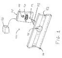
図1は、この発明により構成された回折光学式エンコーダ100の斜視図である。図示のように、エンコーダ100は、3つの基本的部品として、光電式アセンブリ即ちセンサヘッド110と、スケール160と、信号処理器190とを備える。
Detailed Description of Preferred Embodiments
FIG. 1 is a perspective view of a diffractive
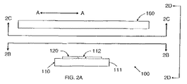
図2Aは、エンコーダ100の側面図である。図2Bは、図2Aに示された線2B−2Bの方向に見たセンサヘッド110の図である。図2Cは、図2Aに示された線2C−2Cの方向に見たスケール160の図である。図2Dは、図2Aに示された線2D−2Dの方向に見たエンコーダ100の端面図である。説明の便宜上、図2A〜2Dに信号処理器190は示されていない。
FIG. 2A is a side view of the
図1および2A〜2Dを参照すると、センサヘッド110は、光源112と、1次検出器アレイ120と、インデックス(即ち基準点)検出器140とを含む。図示のように、光源112と検出器120,140は全て共通の基板111上に搭載されている。1次検出器アレイ120とインデックス検出器140は、シリコンの単一片上に装備されることが好ましい。スケール160は、基板161を備え、その上に回折格子162と2つの回折光学要素(DOE)とが搭載されている。スケール160とセンサヘッド110は、(図2Dに示されるように)固定距離dだけ離れて、概ね対向して配設されている。この結果、スケール160とセンサヘッド110は、図2Aに示された矢印A−A方向に互いに相対的に移動することができる。動作時に、エンコーダ100は、センサヘッド110に対するスケール160の(矢印A−Aの方向の)相対移動をモニタして、センサヘッド110に対するスケール160の相対位置を表す信号を発生する。
Referring to FIGS. 1 and 2A-2D, the
動作時に、光源112は、拡張性、即ち発散性の光のコーン(円錐)102を放射する。光源112は、準単色(またはほぼ単色)の光源であって、垂直空洞表面放射レーザ(VCSEL)を使用して実施できることが好ましい。図1に示すように、センサヘッド110とスケール160は好ましく配設されているので、光コーン102は、スケール160に到達するときに、格子162の一部やDOE166の1つに十分に広く入射する。光コーン102の幾分かは、スケール160を通して伝播し、スケール160によって回折される。この光は、センサヘッド110に戻らないことが好ましい。コーン102内の光の幾分かはまた、反射され、回折されてセンサヘッド110に戻される。センサヘッド110とスケール160が好ましく構成されているので、(1)格子162で回折されてセンサヘッド110に戻される光は、一次的に検出器アレイ120に入射し、また(2)DOE166で回折されてセンサヘッド110に戻される光は、一次的にインデックス検出器140に入射する。以下で更に詳細に説明されるように、検出器アレイ120に入射する光によって、エンコーダ100は、スケール160に対するセンサヘッド110の位置の相対測定値を与えることができる。これに対し、インデックス検出器140に入射する光によって、エンコーダ100は、スケール160に対するセンサヘッド110の位置のインデックス点測定値(即ち、基準点測定値)を与えることができる。
In operation, the
図3A,3Bおよび3Cは、スケール160を更に詳細に示している。具体的には、図3Bおよび3Cは、図3Aに示された領域310の拡大図である。スケール160は、ガラス様の基板161上に形成されることが好ましい。格子162は、図3Bに示すように、光反射性ストライプ164と光透過性ストライプ163を交互に備える。光反射性ストライプ164は、高度に反射性の素材で基板161の領域を被覆することによって形成されることが好ましい。この実施形態では、光透過性ストライプ163は、単に基板161を被覆しないでおくことによって形成されている。透過性ストライプの代わりに、光吸収性ストライプを使用することもできる。図3Cに示すように、もう1つの実施形態では、ストライプを全て反射性とし、ストライプを交互に異なる深さに配設することができる。図3Bに示すタイプの格子162は、「振幅格子」として知られている。図3Cに示すタイプの格子162は、「位相格子」として知られている。
3A, 3B and 3C show the
格子162が図3Bまたは3Cのいずれに示すように実施されているかとは関係なく、各ストライプは、その短辺がスケールの変位方向と平行(即ち、図1の矢印A−Aと平行)に指向された細い矩形であることが好ましい。ストライプの中心間隔(即ち、図3Bおよび3Cに示されているように、ストライプの間隔の左端から左端まで)は、格子162の周期Pを規定する。ストライプは等しく離れていることが好ましい。また、各ストライプの短辺は、格子162の周期Pの1/2にほぼ等しいことが好ましい。所望のシステム性能に依存して、周期Pは典型的には5〜40ミクロンの範囲にあり、20ミクロンが好ましい値である。スケールは、両面の露出したガラス領域に反射防止被覆が施されていることが理想的である。
Regardless of whether the grating 162 is implemented as shown in FIG. 3B or 3C, each stripe has its short side parallel to the displacement direction of the scale (ie, parallel to the arrow AA in FIG. 1). A thin, oriented rectangle is preferred. The center spacing of the stripes (ie, from the left edge to the left edge of the stripe spacing as shown in FIGS. 3B and 3C) defines the period P of the
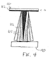
図1に戻ると、格子162は、コーン102からの光を、センサヘッド110に向かって指向された複数の光のコーンに回折する。図2Aに示されたものと同じ方位にあるエンコーダ100を示す図4は、格子162によって回折されてセンサヘッドに向かう光のコーン103のいくつかを示している。回折された光のコーン103は互いに光学的に干渉して、スケール160とセンサヘッド110との間の空間に、複合的な縞様パターンを発生する。
Returning to FIG. 1, the grating 162 diffracts the light from the
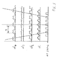
図5は、格子162からの異なる距離において回折光コーン103間の干渉によって形成された縞パターンの強度を示している。図示のように、格子162からの距離d2およびd4において光コーン103間の干渉によって形成された光学的縞パターンは、比較的高コントラストの周期性パターンである。逆に、格子162からの距離d1およびd3において光コーン103間の干渉によって形成された光学的縞パターンは、比較的低コントラストである。格子162からの距離d2およびd4における平面は、自己像形成平面、または「タルボット像形成平面」と呼ばれる。これらのタルボット像形成平面では、回折された光の発散性コーンは、それらが格子において有する同じ相対位相と組み合わされて、本質的に格子162自身の像を形成する。米国特許第5,991,249号で概ね論議されているように、これらの高コントラスト像形成平面は、規則正しく起こり、そして格子といずれかの像形成平面との間の距離は、下式(1)によって計算される。
FIG. 5 shows the intensity of the fringe pattern formed by interference between the diffracted

式(1)において、z0は光源112と格子116との間の距離に等しく、z1は格子162とタルボット自己像平面との間の距離に等しく、Nは整数であり、Pは格子の周期であり、λは光源112によって放射される光の波長である。
In equation (1), z 0 is equal to the distance between the
図5に示すように、(スケールからの距離d2における)第1のタルボット平面は、(スケールからの距離d4における)第2のタルボット平面に対し180度位相がずれている。一般に、隣接するタルボット平面は、互いに180度位相がずれている。隣接するタルボット平面間のこの180度位相ずれに対する理由は、偶数平面(即ち、Nが偶数であるタルボット平面)では、全ての次数の回折光はそれらが格子で有する同じ相対位相と組み合わされるのに対し、奇数平面(即ち、Nが奇数であるタルボット平面)では、0次が180度位相ずれし、また全ての他の次数はそれらが格子で有する同じ相対位相と組み合わされるためである。 As shown in FIG. 5, the first Talbot plane (in the distance d 2 from the scale) is deviated (at a distance d 4 from the scale) 180 degrees out of phase with respect to the second Talbot plane. In general, adjacent Talbot planes are 180 degrees out of phase with each other. The reason for this 180 degree phase shift between adjacent Talbot planes is that in an even plane (ie a Talbot plane where N is an even number) all orders of diffracted light are combined with the same relative phase they have in the grating. In contrast, in the odd plane (ie, the Talbot plane where N is odd), the 0th order is 180 degrees out of phase and all other orders are combined with the same relative phase they have in the grating.
ここで留意されるべき点は、図5に示されたパターンは、0次ビームがそのパターンに貢献した時(例えば、縞パターンが、他の高次の回折ビームと同様に、0次、+1次、−1次間の干渉によって形成される時)の縞パターンの特徴であるということである。0次ビームが消去される場合、縞パターンは図5に示されたものとは有意に異なるように見える。1/2波長遅延のある位相格子の場合、低コントラストの平面はタルボット像形成平面であり、また高コントラストの平面はタルボット像形成平面の間にある。高コントラストの領域内では、振幅格子でのように、縞パターンが元の格子の像として現れることはない。むしろ、位相格子の縞パターンは、一般に図5のタルボット平面に示された周期の1/2の周期をもつ成分によって通常は支配される高調波成分の複雑な組み合わせである。振幅格子でのように、位相格子からの縞パターンの周期は、スケールからの距離に比例して増加する。一般に、位相格子からの縞パターンが最小調波歪みおよび/または雑音を呈する平面を予測することは困難である。 It should be noted here that the pattern shown in FIG. 5 has a zero-order beam when the zero-order beam contributes to the pattern (for example, the fringe pattern is similar to other higher-order diffracted beams in the zero-order, +1 Next, when it is formed by interference between the -1st order), it is a feature of the stripe pattern. When the zero order beam is erased, the fringe pattern appears to be significantly different from that shown in FIG. In the case of a phase grating with a ½ wavelength delay, the low contrast plane is the Talbot imaging plane and the high contrast plane is between the Talbot imaging planes. In the high contrast region, the fringe pattern does not appear as an image of the original grating as in the amplitude grating. Rather, the fringe pattern of the phase grating is a complex combination of harmonic components that are typically dominated by components having a period that is typically one-half the period shown in the Talbot plane of FIG. As with the amplitude grating, the period of the fringe pattern from the phase grating increases in proportion to the distance from the scale. In general, it is difficult to predict a plane in which the fringe pattern from the phase grating exhibits minimum harmonic distortion and / or noise.
従って、0次ビームの消去は、エンコーダによってモニタされる周期性信号の劣化を引き起こすものとみなされる。しかしながら、それでも有利なことは、少なくとも以下の理由に対して0次ビームが消去されたエンコーダを構成することである。即ち、実際的なこととして、本発明の設計のエンコーダでは、高い回折次数は伝播によって速やかに濾過され、そして結果として得られる縞パターンはしばしば純粋なシヌソイド形状に近い。 Therefore, the cancellation of the zero order beam is considered to cause degradation of the periodic signal monitored by the encoder. However, it is still advantageous to construct an encoder in which the zero order beam is canceled for at least the following reasons. That is, as a practical matter, in encoders of the present design, high diffraction orders are quickly filtered by propagation, and the resulting fringe pattern is often close to a pure sinusoidal shape.
上述した位相格子の利点にもかかわらず、この発明にとって好ましい格子は、振幅格子である。(図3Bに示される)振幅格子は、(図3Cに示される)位相格子よりも幅広く商業的に利用可能である。それ故、振幅格子を使用するエンコーダの設計は、さほど高価でなく、しかもスケールの捕捉が容易であるという利点がある。しかしながら、振幅格子の使用は、0次ビームの存在を意味する。0次ビームが存在するエンコーダの設計は、以下で論じられる。 Despite the advantages of the phase grating described above, the preferred grating for the present invention is an amplitude grating. The amplitude grating (shown in FIG. 3B) is more widely commercially available than the phase grating (shown in FIG. 3C). Therefore, the design of an encoder using an amplitude grating has the advantage that it is not very expensive and that it is easy to capture the scale. However, the use of an amplitude grating means the presence of a zero order beam. The design of an encoder in which a zero order beam is present is discussed below.
この発明により構成されたエンコーダでは、センサヘッド110とスケール160は好ましく配設されているので、検出器アレイ120は、タルボット像形成平面の1つに位置する(即ち、上式(1)によって計算されるように、スケールと検出器アレイの検知表面との間の距離がz1に等しくなる)。図2Aおよび2Dから明らかなように、この発明により構成されたエンコーダでは、光源112の上部発光面が、検出器アレイ120の上部(即ち検知)表面とほぼ共平面であることが好ましい。それ故、この発明により構成されたエンコーダでは、距離z0は距離z1にほぼ等しい。z0がz1に等しい場合、上式(1)は下式(2)に簡略化される。
In the encoder constructed according to the present invention, since the
それ故、検出器アレイ120がタルボット像形成平面の1つに配設されることを確実にするために、この発明により構成されたエンコーダでは、(図2Dに示すように)センサヘッド110とスケール160との間の距離dが好ましく調整され、式(2)によってNの整数値について計算されるように、スケール160と検出器アレイ120との間の隔離距離はほぼz0に等しくなる。しかしながら、スケール160と検出器アレイ120との間の実際の距離を確実にz0に等しくすることはほぼ不可能であるので、この距離は好ましく選択され、検出器アレイ120の検知表面がタルボット平面の1つに近い領域内に位置するようにする。この領域の所望サイズが以下で論じられる。
Therefore, in order to ensure that the
図5に示すように、スケールと第1タルボット平面との間の距離はd2である。また、スケールと第nタルボット平面との間の距離はnd2(即ち、d2のn倍)である。検出器アレイを第nタルボット平面に配置することが望まれる場合、スケールと検出器アレイとの間の距離はnd2+または−0.5d2に等しいことが好ましい。それ故、例えば、検出器アレイを第3タルボット平面に配置することが望まれる場合、検出器アレイは、スケールから2.5d2離れた位置とスケールから3.5d2離れた位置との間の領域内に配置されるべきである。この例を続けると、スケールと検出器アレイとの間の距離が3.0d2に等しい場合、検出器アレイは確実に第3タルボット平面に位置することになる。この距離が3.0d2よりも僅かに大きいか小さい場合、縞パターンのコントラストは最適よりも僅かに小さくなり、またエンコーダの精度はそれに対応して僅かに低減される。検出器アレイが所望の位置3.0d2から遠くへ移動されると、縞パターンのコントラストは低減され続け、やがて距離2.5d2または3.5d2で最小値に達する(即ち、コントラストは、これらの位置で最小値になる。これは、タルボット平面が最小コントラストによって特徴付けられた等間隔平面によって分離されているからである)。タルボット平面が最小コントラストの等間隔平面によって分離されているので、nd2+または−0.5d2は、検出器アレイが配置されるべき領域の最大サイズを示すことになる。検出器アレイがスケールからnd2+または−0.5d2離れた位置に配置される場合、エンコーダの性能は増加する。検出器アレイがスケールからnd2+または−0.1d2離れた位置に配置される場合に、エンコーダの性能はさらに増加する。より一般的には、検出器アレイ120は、2つの平面、即ちスケールからnd2+xd2離れた第1平面と、スケールからnd2−xd2離れた第2平面とによって制限された領域内に位置することが好ましい。ここで、xは1/2以下である。好ましいxの値は0.2であり、より好ましいxの値は0.1である。
As shown in FIG. 5, the distance between the scale and the first Talbot plane is d 2. The distance between the scale and the nth Talbot plane is nd 2 (that is, n times d 2 ). If it is desired to place the detector array in the nth Talbot plane, the distance between the scale and the detector array is preferably equal to nd 2 + or −0.5d 2 . Thus, for example, if it is desired to place the detector array to a third Talbot plane, the detector array, between location and the scale 2.5d 2 away from the scale of 3.5D 2 away Should be placed in the area. Continuing with this example, when the distance between the scale and the detector array is equal to 3.0d 2, the detector array is located to ensure that the third Talbot plane. If this distance is slightly larger or smaller than 3.0d 2 , the fringe pattern contrast will be slightly less than optimal and the encoder accuracy will be correspondingly slightly reduced. As the detector array is moved away from the desired position 3.0d 2 , the fringe pattern contrast continues to decrease and eventually reaches a minimum at distances 2.5d 2 or 3.5d 2 (ie, the contrast is These values have a minimum because the Talbot planes are separated by equally spaced planes characterized by minimum contrast). Since the Talbot planes are separated by an equidistant plane with minimum contrast, nd 2 + or −0.5d 2 will indicate the maximum size of the region in which the detector array is to be placed. If the detector array is placed nd 2 + or −0.5d 2 away from the scale, the performance of the encoder increases. Encoder performance is further increased when the detector array is placed at a position nd 2 + or −0.1d 2 away from the scale. More generally, the
上述したように、0次ビームが消去される場合は、検出器アレイとスケールとの間隔に関係なく、高コントラストの縞パターンが検出器アレイに入射する。従って、0次ビームをほぼ消去する位相格子(図3Cに示される)を有したスケール160を使用して、検出器アレイとスケールとの間隔について先に論じられた制限を緩和するは有利である。そのような実施形態では、上側ストライプと下側ストライプとの距離(または下側ストライプの深さ)は、光源112によって発生される光の1/4波長のN倍にほぼ等しいことが好ましい。ここでNは奇数である。そのような位相格子を使用するもう1つの利点は、それが光学的縞パターンの周期を2の係数で低減し、これによりエンコーダの分解能を2の係数で潜在的に増加する点である。この代わりに、0次ビームが存在する位相格子を使用してエンコーダを製造することが望まれる場合は、上側ストライプと下側ストライプとの距離は、(N+x)×(光源112によって発生される光の波長の1/4)に等しいことが好ましい。ここでNは奇数であり、またxは1/2未満の小さい数である。
As described above, when the zero-order beam is erased, a high-contrast fringe pattern enters the detector array regardless of the distance between the detector array and the scale. Therefore, it is advantageous to use the
図5に示すように、干渉縞は周期的であって、周期Tによって特徴付けられる。格子162は拡張する光のコーンによって照明されるので、縞の周期Tは一般に下式(3)によって示されるように、格子からの距離の関数となる。
As shown in FIG. 5, the interference fringes are periodic and are characterized by a period T. Since the
式(3)において、z0は光源112とスケール160との間の光路長であり、z1はスケールと検出器アレイ120との間の光路長であり、Pは格子の周期であり、eは光源112と検出器アレイ120との間のオフセット(即ち、z0とz1との間の差)であり、Kはスケール係数である。
In equation (3), z 0 is the optical path length between the
式(3)から判るように、光源と格子との間の距離(z0)が検出器アレイと格子との間の距離(z1)に等しい特別な場合には(即ち、e=0)、スケール係数Kは2となり、それ故干渉縞の周期Tは常に格子の周期Pの2倍も大きな一定値に等しい(即ち、T=2P)。上述したように、光源112の上部発光面が検出器アレイ120とほぼ共平面であることが好ましいので、この発明により構成されたエンコーダでは、光源と格子との間の距離(z0)は、格子と検出器アレイとの間の距離(z1)にほぼ等しい。従って、エンコーダ100では、検出器アレイ120に入射する縞の周期Tは常に定数2Pにほぼ等しい。
As can be seen from equation (3), the special case (ie, e = 0) where the distance between the light source and the grating (z 0 ) is equal to the distance between the detector array and the grating (z 1 ). , The scale factor K is 2, so that the fringe period T is always equal to a constant value that is twice as large as the grating period P (ie T = 2P). As described above, it is preferable that the upper light emitting surface of the
動作時に、スケール160がセンサヘッド110に対して図2Aに示された矢印A−A方向に相対移動すると、検出器アレイ120に入射する縞パターンは、検出器アレイ120を矢印A−A方向に横切って移動する。検出器アレイを横切る入射縞パターンの移動は、入射縞パターンと検出器アレイとの間の位相角の変化と等価である。検出器アレイ120とそれに関連した信号処理器190とはこの位相角をモニタし、それによってスケール160に対するセンサヘッド110の相対位置をモニタする。
In operation, when the
検出器アレイは、検出器アレイと該検出器アレイに入射した縞パターンとの間の位相角の測定を容易にするように構成された複数の光検出器のアレイとして構築されることが好ましい。参照によって組み込まれた「高調波抑制光検出器アレイ」なる名称の共出願中の米国特許出願第60/316,121号[代理人整理番号MCE−018(111390−140)]は、検出器アレイ120の実施に使用され得るいくつかの検出器アレイを開示している。しかしながら、アレイと入射縞パターンとの間の位相角の測定を可能にする検出器アレイであれば、如何なるものでも検出器アレイ120の実施に使用され得る。検出器アレイ120によって発生された出力信号は信号処理器190に入力される。信号処理器190は検出器アレイ120と該アレイ120に入射した縞パターンとの間の位相角を表す出力信号を発生することが好ましい。
The detector array is preferably constructed as an array of a plurality of photodetectors configured to facilitate measurement of the phase angle between the detector array and the fringe pattern incident on the detector array. Co-pending US Patent Application No. 60 / 316,121 [Attorney Docket No. MCE-018 (111390-140)] entitled "Harmonic Suppressed Photodetector Array", incorporated by reference, is a detector array. Several detector arrays are disclosed that can be used in 120 implementations. However, any detector array that allows measurement of the phase angle between the array and the incident fringe pattern can be used to implement the
図6は図2Bに示された図と同様にセンサヘッド110の上面を示す図であるが、図6は追加された詳細を示している。図示のように、検出器アレイ120は、それぞれが線L−L方向に(即ち、光検出器の長さ方向に沿って)延びた長軸と、線W−W方向に(即ち、光検出器の幅方向に沿って)延びた短軸とを有する複数の矩形光検出器を含んでいる。検出器アレイ120は、4ビン・アルゴリズムで使用されるために構成されていることが好ましい。従って、アレイ中の光検出器は、4つのボンディングパッド121に電気的に接続されていることが好ましい。処理回路190(図示せず)は、ボンディングパッド121に電気的に接続されている。これは、アレイ120のモニタを可能にするためである。光源112は、2つのボンディングパッド113に電気的に接続され、そしてそこに印加される電気的信号よって制御されることが好ましい。VCSEL112の開口114もまた図6に示されている。VCSELによって放射された全ての光は、この開口を通過する。
FIG. 6 is a view showing the top surface of the
これもまた図6に示されているように、インデックス検出器140は、中央光検出器142と、この中央光検出器142の両側に配設された2つの端部光検出器144とを含む3セル構成で実施されることが好ましい。中央光検出器142は、ボンディングパッド143に電気的に接続されている。端部光検出器144のそれぞれは、ボンディングパッド145に電気的に接続されている。処理回路190(図6には示されていない)は、ボンディングパッド143,145に電気的に接続されている。これは、インデックス検出器140のモニタを可能にするためである。中央光検出器142は光源112と好ましく整列されているので、開口114から線L−Lと平行に延びた線は中央光検出器142を二分する。
As also shown in FIG. 6, the
図1を参照すると、光源112から放射された発散性光コーン102がDOE166を照明しているように示されている。ここで認められるべき点は、スケール160とセンサヘッド110の一方が他方に対して図2Aに示された矢印A−A方向に移動されるときに、DOE166が光コーン102に出入りするということである。DOE166が光コーン102によって照明されているときに、DOE166はコーン102からの光をインデックス検出器140へ向けて回折する。DOE166はアナモルフィックゾーン板レンズを使用して実施されることが好ましい。DOE166は、光コーン102によって照明されているときに、光源112の「線像」を発生することが好ましい。即ち、DOE166は、「光の線」を回折してインデックス検出器140に戻すことが好ましい。DOE166によって発生され、センサヘッド110に入射した線像は、図6に示す線L−Lとほぼ平行であることが好ましい。
Referring to FIG. 1, a diverging
明瞭にするために、1つのDOE166だけが図1のスケール160に示されている。しかしながら、図2Cおよび3Aに示されているように、スケール160は、格子162の両側に配設された2つのDOE166を含むことができる。スケール160に到達する光のコーン102は、格子162の一部とDOE166の1つを照明するに十分な大きさであることが好ましい。しかしながら、2つのDOE166がスケール160に含まれる場合、スケール160とセンサヘッド110は、エンコーダ100を形成するときの方位に関係なく組み立てられる。即ち、スケール160が2つのDOE166を含む場合は、スケール160が正しく設置されているか逆さまに設置されているかに関係なく、DOE166の1つは光コーン102によって照明される。スケール160は、対称的に配設されていない2つのDOE166を含むこともできる(例えば、1つのDOEはスケールの中心付近に配設され、もう1つのDOEはスケールの端部付近に配設されている)。
For clarity, only one
動作時にスケール160とセンサヘッド110の一方は他方に対して(図2Aに示された矢印A−A方向に)移動させられるので、DOE166によって発生された線像はインデックス検出器140を横切るように掃引する。スケール160がセンサヘッド110に対して矢印A−A方向に距離Dだけ移動すると、DOE166によって発生された線像はKDに等しい距離だけセンサヘッド110を横切って移動する。ここで、Kは式(3)からのスケール係数である。それ故、eが0である場合(即ち、式(3)に記述されているようにZ0がZ1に等しい場合)については、スケール160がセンサヘッド110に対して変位させられているので、DOE166によって発生された線像は、スケールが移動する速度の2倍の速度で、センサヘッド110を横切るように移動する。DOE166によって発生された線像は、DOE166が直接光源112を超える時(即ち、エンコーダが図1に示すように構成される時)にのみ、インデックス検出器140の中央光検出器142に中心をもつ。処理回路190は、インデックス検出器140に入射する光を表す出力信号を発生する。この出力信号はインデックス信号と呼ばれることもある。このインデックス信号は、DOE166によって発生された線像がインデックス検出器140を横切って掃引する毎のパルスによって特徴付けられることが好ましい。ここで認められるべき点は、そのようなパルスが、スケール160とセンサヘッド110の相対方位のインデックス点(即ち基準点)測定値を与えるということである。検出器アレイ120によって発生される、スケール160とセンサヘッド110との間の距離または変位の測定値は、相対測定値である。これは、アレイ120に入射した縞パターンが周期的信号であるからである。しかしながら、DOE166によって発生された線像は、光源120とDOE166とインデックス検出器140が全て1つの特別な方位にあるときにのみ、インデックス検出器140に入射する。これ故に、インデックス信号は、基準測定値を与えるのである。
In operation, one of
処理回路190は、種々のアルゴリズムを使用してインデックス信号を発生する。インデックス検出器140によって発生される出力信号は、光源の強度変化や、迷光や、センサヘッド110とスケール160の不整合によって変化することがあるが、処理回路190は、このような変化に反応しないアルゴリズムを使用することが好ましい。このインデックス信号は、DOE166によって回折された線像がインデックス検出器140を横切って掃引する毎のパルスによって特徴付けられる。このパルスの幅は、格子162の周期Pにほぼ等しいことが好ましい。そのようなパルス幅によって、このパルスは、格子162によって発生されたパターンの単一縞を独特に識別するか、それに対応することができる。1つの好ましい実施形態では、(図6に示された線W−Wの方向に測定されたように)中央光検出器142の幅は、格子162の周期Pの2倍にほぼ等しい。この実施形態では、インデックス信号は、DOE166によって発生された線像の中心が中央光検出器142に入射するときはいつでも高いことが好ましく、また他の全ての時は低いことが好ましい。
The
図7は、線像700が矢印702によって示されるようにアレイを左から右へ横切って移動するときに、インデックス検出器140によって発生される出力信号の一般的な形状を示している。曲線Aは、線像700が光検出器上を移動するときに、左端光検出器144によって発生される出力信号の形状を示している。曲線Bは、線像700が光検出器上を移動するときに、中央光検出器142によって発生される出力信号の形状を示している。最後に、曲線Cは、線像700が光検出器上を移動するときに、右端光検出器144によって発生される出力信号の形状を示している。未処理の出力信号A,B,Cからインデックス信号を発生するための1つの好ましい方法は、処理回路190が下式(4)に従って信号S1およびS2を発生することである。
FIG. 7 shows the general shape of the output signal generated by the
図7はまた、図7に示された未処理信号A,B,Cから式(4)に従って発生された信号S1およびS2を示している。式(4)から明らかな点は、両信号S1およびS2が迷光とは無関係であるということである。これは、インデックス検出器140の3つ全ての光検出器に入射する光が減算されるか、S1およびS2に貢献しないためである。
FIG. 7 also shows the signals S 1 and S 2 generated according to equation (4) from the raw signals A, B, C shown in FIG. The obvious point from equation (4) is that both signals S 1 and S 2 are independent of stray light. This is because the light incident on all three photodetectors of the
図示のように、信号S1は一般に、線像700の中心が中央光検出器142に入射したときに、正のピークを有する。加えて、信号S1は、線像における固有の回折効果をトレース可能な多数のサイドローブまたはリンギングを有する。同様に、信号S2は一般に、線像700の中心が中央光検出器142に入射したときの負のピークと、線像における回折効果からの多数のサイドローブを有する。信号S1およびS2からインデックス信号(index signal)を発生するための1つの好ましい方法が下式(5)に示されている。
As shown, the signal S 1 generally has a positive peak when the center of the line image 700 is incident on the
式(5)において、Oは一定のオフセットであり、これはS1およびS2中の予測サイドローブピークよりも大きいことが好ましく、またS1の最小予測最大値よりも小さいことが好ましい。 In the formula (5), O is a constant offset, which is preferably preferably greater than the predicted sidelobe peaks in S 1 and S 2, also smaller than the minimum predicted maximum value of S 1.
図7はまた、式(5)によって発生されるインデックス信号(INDEX SIGNAL)を示している。図示のように、このインデックス信号は、DOE166によって発生される線像の中心が中央光検出器142に入射するときに、1または高い値であり、他の全ての時に0または低い値であるという所望の特徴を有する。そのようなインデックス信号は、DOE166によって発生される線像がインデックス検出器140を横切って掃引する毎のパルスによって特徴付けられる。
FIG. 7 also shows the index signal (INDEX SIGNAL) generated by equation (5). As shown, this index signal is 1 or higher when the center of the line image generated by the
式(5)の使用はインデックス信号を発生する好ましい方法ではあるが、ここで認められるべき点は、他の方法も同様に使用できるということである。例えば、信号S1が一定の選択値よりも大きいときはいつでも、インデックス信号を単純に高い値に設定することができる。 Although the use of equation (5) is the preferred method of generating the index signal, it should be noted that other methods can be used as well. For example, whenever the signal S 1 is greater than a certain selected value, it is possible to set the index signal simply high.
端部光検出器144の幅は、中央光検出器142の幅と等しいことが好ましい。このことにより、迷光が信号S1およびS2に確実に貢献しなくなる。しかしながら、ここで認められるべき点は、他の実施形態では、端部光検出器144の幅が中央光検出器142の幅と異なることができる。中央光検出器142と異なる幅の端部光検出器144を使用する1つの利点は、そのような構成が、線像の回折効果を平均化することによって、信号S1およびS2のサイドローブを減少できる点にある。また検出器の幅や間隔を調整すると、端部光検出器からの信号のリンギングを中央光検出器からの信号のリンギングと相殺することが可能になる。このような方法が使用される場合、式(4)中の未処理信号の重み付けは、信号S1およびS2が依然として迷光に反応しないように、変更されることが好ましい。更に異なる実施形態では、インデックス検出器140は、中央光検出器142だけを使用することによって、かつ端部光検出器144を省略することによって、構成できる。しかしながら、このような方法は好ましいものではない。何故ならば、結果として生ずるインデックス信号が余りにも雑音や不整合に反応しやすくなるからである。
The width of the
図8はインデックス検出器140の別の実施形態を示している。この実施形態では、検出器140は2つの2セル検出器140Aおよび140Bを含む。2セル140Aは、中央検出器142と、左端検出器144とを有する。2セル140Bは、中央検出器142と、左端検出器144とを有する。2つの2セルは好ましく位置決めされているので、光源120から線L−L方向に延びる線は、図6に示すように、両2セル140Aおよび140Bの中央検出器142を二分する。ここで認められるべき点は、2セル140A,140Bを使用して上式(4)に従って信号S1およびS2が簡単に発生されるということである。例えば、2つの中央検出器142によって発生された出力信号を加算し、そしてその和から2つの端部検出器144によって発生された出力信号を減算することによって、信号S1は単純に発生される。
FIG. 8 shows another embodiment of the
図9は、この発明により構成された回折光学式エンコーダ100の好ましい実施形態の端面図である。図9は、図2Aに示された線2D−2Dの方向に見たエンコーダ100の図を示している。図2Dと図9との主な違いは、図9ではセンサヘッド110が格子160に対して(ほぼ平行である代わりに)傾いて示されている点である。より具体的には、センサヘッド110は、スケール160の移動方向にほぼ平行な(即ち、図2Aに示された線2A−2Aに平行な)軸を中心として傾いている。エンコーダ100の好ましい実施形態は、図9に示された傾斜を含む。図9に示すようにセンサヘッド110をスケール160に対して傾けると、少なくとも2つの利点が与えられる。第1に、その傾きは、スケール160から反射されて光源120に戻る光の量を減少させる。第2に、その傾きは、検出器アレイ120およびインデックス検出器140に達する光の量を増加させ、かつバランスさせる。
FIG. 9 is an end view of a preferred embodiment of a diffractive
一般に、スケールから反射された光が光源112に入ることは望ましいことではない。第1に、好ましいVCSEL光源でさえも、レーザ発振媒体に再び入る反射光によって悪い影響を受ける。第2に、レーザの放射面が幾分か反射性であるので、この面に達する光はスケール160に向けて反射される。この複合的に反射および/または回折された迷光は、適切に制御されていなければ、検出信号に外来成分を生じる。本発明では、光電平面とスケールとの間の意図的な傾斜が、これら外来ビームを検出器から遠ざけるように選択されている。図9に示すようにスケールに対してセンサヘッド110を傾けると、効果的に(1)スケールから反射された光が光源112に再入射することを防止するか、そのような光の量を有意に減少させ、また(2)光源から反射された光が検出器に達しないようにすることを確実にするか、そのような光の量を有意に減少させる。
In general, it is not desirable for light reflected from the scale to enter the
センサヘッド110とスケール160の間に傾斜を導入する第2の機能は、検出器に到達する光のレベルを増加し、バランスさせることである。センサヘッド110は傾いていて、鏡面反射した光のコーンのピーク強度を検出器アレイ120とインデックス検出器140とのほぼ中間に位置させることが好ましい。このことにより、2つの検出器領域120,140に入射する光の量は最大化される一方で、両領域上の光強度の低下は最小化される。
The second function of introducing a tilt between the
上述したように、光源112とスケール160との間の光路長が、スケール160と検出器アレイ120との間の光路長にほぼ等しくなるように、エンコーダ100を構成することは有利である。そのようにすることで、検出器アレイ120に入射する縞パターンの周期は、センサヘッド110とスケール160との間の距離と確実に無関係になる。光源112が(図1に示されるように)、センサヘッド110の平面に直交した方向に光を放射するVCSELとして実施される時、検出器アレイ120の上面を光源112の放射面と共平面にすることによって、これらの光路長を等しくすることが達成できる。しかしながら、光源と光検出器はそれぞれ特別な厚みによって典型的に特徴付けられるので、実際にこれらの表面を共平面にすることは難しい。
As described above, it is advantageous to configure
図10Aは、これらの表面を共平面にするための1つの技術を示している。図10Aに示されるように、トレンチ900がセンサヘッド110の基板111中にエッチングによって形成されている。検出器アレイ120の光検出器か光源112のいずれかが、トレンチ900内にボックス910で示されるように配設される。ここで認められるべき点は、そのようなトレンチを使用すると、検出器アレイ120と光源112の厚さの差を補償できるということである。トレンチ900のようなトレンチは、基板111を機械加工することによって、あるいはフォトリソグラフィ技術を使用することによって設けられる。
FIG. 10A shows one technique for making these surfaces coplanar. As shown in FIG. 10A, a
図10Bは、これらの表面を共平面にするためのもう1つの技術を示している。図10Bに示されるように、スペーサ912がセンサヘッド112の基板111の上面に配設されている。ボックス910で示されるように、検出器アレイ120の光検出器か光源112のいずれかが、そのようなスペーサ上に配設される。所望厚みのスペーサ112のようなスペーサは、基板111上に、例えば材料体積によって形成されるか、予め形成されたスペーサを基板111の上面に接着することによって形成される。
FIG. 10B shows another technique for making these surfaces coplanar. As shown in FIG. 10B, the
図10Cおよび10Dは、VCSELの代わりにエッジ放射レーザダイオードを使用して、如何にして光源112が実施できるかを示している。それらはまた、光源112とスケール160の間の光路長を、スケール160と検出器アレイ120の間の光路長に等しくするための他の戦略を示している。図10Cでは、光源112は、センサヘッド110の上面に基本的に平行な方向に光を放射するエッジ放射レーザダイオードを使用して実施されている。この実施形態では、センサヘッド110はまた、光源112の光路に配設された反射ミラー920を含んでいる。ミラー920は、光源112によって放射された光のコーンを、スケール(図示せず)に向けて上向きに反射する。図10Dでも、光源112はエッジ放射レーザダイオードを使用して実施されている。この実施形態の光源は、センサヘッド110の基板111に設けられたトレンチ900内に配設されている。トレンチ900の1つのエッジ903は反射性に形成されている。このため、エッジ903は、光源112によって放射された光のコーンを、スケール(図示せず)に向けて上向きに反射する。ここで認められるべき点は、ミラー920や反射性エッジ903は、米国特許第6,188,062号に開示されているように、反射性プリズムやエッチングされた折り畳みミラーを使用して実施できるということである。図10Cおよび10Dに示された配置はそれぞれ、光源112とスケールとの間の光路長に影響を与える。ここで認められるべき点は、そのような配置は、光源112とスケールの間の光路長をスケールと検出器アレイ120の間の光路長に等しくすることに使用できるということである。
FIGS. 10C and 10D show how the
この代わりに、光源112とスケール160の間の光路(Z0)をスケール160と検出器アレイ120の間の光路(Z1)に等しくするための図10A〜10Dで示唆されたトレンチやスペーサを使用するコストを回避するために、等しい光路長を有する概念と、スケールと検出器アレイとの間の距離とは無関係な縞周期とを放棄することができる。そのような場合、検出器アレイ120に入射した縞の周期Tは、格子の周期Pと比例し、そして上式(3)によって与えられる。そのようなエンコーダを設計するときに、スケールと検出器アレイとの間のスケール係数を校正すること、並びにそのエンコーダを最適化することが望ましい。
Alternatively, the optical path between the
理想的な場合、即ちz0とz1が等しく、かつ他の不整合がない場合には、エンコーダのスケール係数はほぼ2に等しい(即ち、検出器アレイに入射した縞の周期Tが格子の周期Pの2倍に等しいので)。しかしながら、実際には、この発明によって構成された光学式エンコーダに関連する実際のスケール係数は、確実に等しくではないが、2に近づく傾向がある。一般にスケール係数が確実に2に等しくはならない理由は、十分正確に成分を測定すること、並びにz0を確実にz1に等しくするに十分精密にスペーサ/トレンチを製造することが困難だからである。また不整合のような他の要因もスケール係数を理想値の2から変動させることに貢献する。最後に、光学式エンコーダにとって好ましいスケール係数は、縞または検出器周期の実際の値に直接関係することなく、最高精度の性能を与えるものである。 In the ideal case, i.e., z 0 and z 1 are equal and there are no other mismatches, the encoder scale factor is approximately equal to 2 (ie, the period T of the fringes incident on the detector array is equal to that of the grating). Because it is equal to twice the period P). In practice, however, the actual scale factor associated with an optical encoder constructed in accordance with the present invention is not necessarily equal but tends to approach two. In general, the reason that the scale factor does not always equal 2 is that it is difficult to measure the components sufficiently accurately and to make the spacer / trench precisely enough to ensure that z 0 equals z 1. . Other factors such as inconsistencies also contribute to changing the scale factor from the ideal value of 2. Finally, the preferred scale factor for an optical encoder is one that gives the highest accuracy performance without being directly related to the actual value of the fringes or detector period.
この基準(最良の精度)を与えることによって、この発明によって構成された光学式エンコーダのスケール係数を決定し、そして測定されたスケール係数の観点からそのエンコーダを校正するための好ましい方法が論ぜられる。校正センサヘッドと校正スケールが製造されることが好ましい。しかしながら、校正スケールは、ほぼ均一な周期によって特徴付けられるのでなく、むしろ格子162と同様の校正格子を有する(格子162がそうであることが好ましいように)。この校正格子はいくつかの異なる区分を有し、各区分は独特な周期によって特徴付けられる。1つの区分は設計周期Pで製造されている(例えば、Pは20ミクロンに等しい)。他の区分は、Pから僅かにずれた周期によって特徴付けられる。校正格子の種々の区分は、Pの約0.5%に相当する漸増ステップでPの回りの周期範囲に広がっていることが好ましい。即ち、種々の区分は、約P、0.995P、1.005P、0.990P等である周期を有する。本発明者は、+/-3%の周期の範囲が典型的に最適周期を含んでいることを観察している。勿論、当業者には明らかなように、最良性能がその範囲の端点で観察される場合は、より広い範囲となる新たな校正格子が製造されるべきである。校正の種々の区分は、共通基板上に空間的に分布され、かつ容易な識別と選択のために分離されているべきである。使用と整合を容易にするために、種々の区分の軸は平行となるべきである。校正センサヘッドは、設計点2Pにほぼ等しい周期Tのアレイに入射した縞パターンの位相角を測定するために、(例えば、「高調波抑制光検出器アレイ」なる名称の米国特許出願第60/316,121号[代理人整理番号MCE−018(111390−140)]に記載されている方法の1つを使用して)好ましく構成された校正検出器アレイを含んでいる。校正センサヘッドと校正スケールは、校正エンコーダを形成するように構成される(例えば、図2A〜2Dに示されるように)。
By giving this criterion (best accuracy), a preferred method for determining the scale factor of an optical encoder constructed according to the invention and calibrating the encoder in terms of the measured scale factor is discussed. . A calibration sensor head and a calibration scale are preferably manufactured. However, the calibration scale is not characterized by a substantially uniform period, but rather has a calibration grating similar to the grating 162 (as preferably the
校正エンコーダのエンコーダスケール係数が正確に2に等しい場合(そして他の変動効果がない場合)、校正検出器アレイが周期Pによって特徴付けられる校正格子の区分で使用されるときに、校正エンコーダは最も精密な結果を与える。しかしながら、通常は校正検出器アレイが校正格子の他の区分で使用されるときに、最も精密な結果が与えられる。校正エンコーダは、校正格子の区分のそれぞれを使用してテストされることが好ましい。これは、校正格子のどの区分が最も精密な結果を与えるかを決定するためである。典型的には、各テストの精度は、格子運動の同時測定をなす変位真理センサとエンコーダ出力との間のrms(二乗平均)差によって判定される。レーザ干渉計は、真理センサとしてうまく使用されている。 When the encoder scale factor of the calibration encoder is exactly equal to 2 (and there is no other variation effect), the calibration encoder is most useful when the calibration detector array is used in the section of the calibration grid characterized by period P. Give precise results. However, the most accurate results are usually given when the calibration detector array is used in other sections of the calibration grid. The calibration encoder is preferably tested using each of the calibration grid sections. This is to determine which section of the calibration grid gives the most accurate results. Typically, the accuracy of each test is determined by the rms (root mean square) difference between the displacement truth sensor that makes simultaneous measurements of grid motion and the encoder output. Laser interferometers are successfully used as truth sensors.
校正エンコーダは、周期Pの格子で動作するように設計されているので、最も精密な結果は一般に周期FPの校正格子区分から得られる。従って、測定された校正係数Fは、操作用エンコーダの製造中に使用されるべきであると仮定できる。具体的には、操作用エンコーダが周期FPの格子を使用するか、検出器アレイ周期TがT/Fに修正されるべきである。 Since the calibration encoder is designed to work with a grating of period P, the most accurate results are generally obtained from a calibration grid section of period FP. It can therefore be assumed that the measured calibration factor F should be used during the manufacture of the operational encoder. Specifically, the operating encoder should use a grating with period FP or the detector array period T should be modified to T / F.
この点において、校正スケールの代わりにスケール160を使用することによって、また校正センサヘッドの代わりにセンサヘッド110を使用することによって、この発明によるエンコーダが多数製造できる。この発明によるエンコーダを構成する1つの方法は、(1)周期FPによって特徴付けられる格子162を有するスケールと、(2)2Pにほぼ等しい周期Tによって特徴付けられる入射縞パターンの位相角を測定するために構成された検出器アレイ120を有するセンサヘッドとを使用することである。この方法の1つの問題は、格子162の周期FPが標準長さ単位(即ち、ミクロンやミル)の整数になりそうもない点である。かくして、例えば、そのような格子の格子周期は、より典型的な20ミクロンの代わりに、20.2ミクロンになることもある。従って、この発明によるエンコーダを構成するための好ましい方法は、(1)周期Pによって特徴付けられる格子162と、(2)2Pをスケール係数Fで割ったものにほぼ等しい周期を有する入射縞パターンの位相角を測定するために構成された検出器アレイ120を有するセンサヘッドとを使用することである。後者の方法は、この発明により構成されるどの世代のセンサヘッドでも、工業的な標準尺度と相互交換可能に使用できるようにするので、より好ましいものである。
In this regard, a number of encoders according to the present invention can be manufactured by using the
インデックス検出器140がエンコーダに含まれている場合に認められるべき点は、校正スケール係数によってインデックス検出器要素の幅を調整することもまた望ましいということである。例えば、インデックス検出器140の中央光検出器の幅を、格子162の周期Pをスケール係数Fで割ったものにほぼ等しくすることは有利である。
It should be appreciated that when
図11Aおよび11Bは、この発明により構成されるエンコーダに組み入れられる付加的特徴を示している。図11Aおよび11Bはそれぞれ、図2Aと同じ見地から見られた回折光学式エンコーダ100の側面図を示している。図11Aは、センサヘッド110から上向きにスケール160に向かう発散性の光コーン102を示している。図11Aはまた、スケール160の格子162によって回折されて下向きに検出器アレイ120に向かう3つの光ビームを示している。具体的に図11Aは、左右の境界が参照符合1000によって示された0次ビームと、左右の境界が参照符合1001によって示された−1次ビームと、左右の境界が参照符合1003によって示された−3次ビームとを示している。図示のように、0次ビームと−1次ビームと−3次ビームは全て検出器アレイ120に入射する。ここで認められるべき点は、他のビーム(例えば、正の1次および3次、並びに正及び負の5次ビーム)もまた検出器アレイ120に入射するが、説明の便宜上、これらのビームは図10Aには示されていないということである。図11Aに示されたエンコーダに関する1つの問題は、多数の回折ビームが全て検出器アレイ120に入射し、これらビームの存在が検出器アレイ120に入射する結果的な干渉縞の質を劣化させる点である。
FIGS. 11A and 11B illustrate additional features incorporated into an encoder constructed in accordance with the present invention. 11A and 11B each show a side view of the diffractive
図11Bに示されたエンコーダ100は図11Aに示されたものと同様であるが、図11Bのエンコーダはマスク1010を付加的に含んでいる。図示のように、マスク1010は、スケール160に近接して、センサヘッド110とスケール160との間に配置されている。マスク1010はまた中央開口1012を規定する。マスク1010は、コーン102内の光のほとんどがスケール160に達することを防止する。即ち、開口1012を通過する光だけがスケール160に到達する。マスク1010は、吸収性素材によって作られていることが好ましい。これは、マスク1010に入射する光が単純に吸収され、センサヘッド110に向けて反射されることがないからである。マスク1010は、スケール160で回折されてスケールヘッド110に戻るビームの角度範囲を制限する利点がある。図11Bに示されたエンコーダでは、0次ビームおよび−1次ビームは検出器アレイ120に入射するが、−3次ビームは検出器アレイ120に入射しない。ここで認められるべき点は、3次ビームが検出器アレイ120に入射しない場合、全ての高次のビームもまた検出器アレイに入射しない(即ち、高次ビームは、図示の−3次ビームよりも検出器アレイ120の右または左に変位させられる)、ということである。従って、マスク1010は、検出器アレイ120に入射した干渉縞の質を、不要な高次ビームを除去することによって、有利に改良する。動作時に、マスク1010とセンサヘッド110は、互いに固定された関係にあることが好ましい。そして、スケール160は、センサヘッド110に対し(図11Bに示された構成で左右に)相対移動させられる。
The
「高調波抑制光検出器アレイ」なる名称の米国特許出願第60/316,121号[代理人整理番号MCE−018(111390−140)]で論議されているように、好ましい検出器アレイは3次高調波には反応しない。また、50−50デューティサイクルによって特徴付けられる格子を使用すると、全ての偶数次のビームが検出器アレイ120に到達することを防止できる。従って、開口1012は、3次または4次ビームが検出器アレイに達しないことを確実にするように、小さいものである必要はない。開口1012は矩形であり、そしてその開口の幅は、5次回折ビームが検出器アレイ120に到達することを防止するに十分小さいことが好ましい。開口1012の高さは、コーン102からの光が格子162とDOE166の双方を照明するように選択されることが好ましい。
As discussed in US Patent Application No. 60 / 316,121 [Attorney Docket No. MCE-018 (111390-140)] entitled “Harmonic Suppressed Photodetector Array”, a preferred detector array is 3 Does not respond to second harmonics. Also, using a grating characterized by a 50-50 duty cycle can prevent all even order beams from reaching the
この発明により構成されるエンコーダの1つの好ましい実施形態では、センサヘッド110とスケール160との間の距離dはほぼ4.7mmに等しく、光源112はVCSELを使用して実施され、そのコーン角度は約17度に等しく、VCSELによって放射される光の波長はほぼ850nmに等しく、センサヘッド110とスケール160との間の傾斜角度はほぼ8度に等しく、格子162の周期Pはほぼ20ミクロンに等しく、検出器アレイ120は40ミクロンにほぼ等しい周期を有する入射縞パターンをモニタするために構成されている。他の好ましい実施形態では、矩形開口1012は、0.4ミリメータにほぼ等しい幅と1.2ミリメータにほぼ等しい高さとによって特徴付けられる。この矩形開口1012を規定するマスク1010は、センサヘッド110とスケール160との間に配設される。また、マスク1010は、250ミクロンにほぼ等しい距離だけ、スケール160から離されている。
In one preferred embodiment of an encoder constructed according to the present invention, the distance d between the
改良された回折光学式エンコーダを構成するいくつかの方法が開示されてきた。ここで認められるべき点は、これらの方法の1以上を組み入れることによって、いくつかのエンコーダがこの発明により構成されるということである。例えば、この発明により構成される1つのエンコーダは、インデックス検出器を含むが、マスクを含まない(例えば、図11Aおよび11Bに示すように)。同様に、この発明により構成される1つのエンコーダは、マスクを含むが、インデックス検出器を含まない。また、この発明により構成される1つのエンコーダは、マスクとインデックス検出器の双方を含む。 Several methods of constructing an improved diffractive optical encoder have been disclosed. It should be appreciated that several encoders are constructed in accordance with the present invention by incorporating one or more of these methods. For example, one encoder constructed in accordance with the present invention includes an index detector but does not include a mask (eg, as shown in FIGS. 11A and 11B). Similarly, one encoder constructed in accordance with the present invention includes a mask but does not include an index detector. One encoder constructed according to the present invention includes both a mask and an index detector.
ここに包含された発明の範囲から逸脱することなく、上記装置に対してある程度の変更がなされるので、上記の説明に含まれたり、添付の図面に示された全ての事項は、制限的なものではなく、説明的なものであると解釈されるべきである。 Certain modifications may be made to the apparatus without departing from the scope of the invention encompassed herein, so that all matters contained in the above description or shown in the accompanying drawings are restrictive. It should be construed as illustrative rather than mere.
Claims (13)
B.センサヘッドと
を備える光学式エンコーダであって、
前記スケールは、光学的格子と光学的要素とを含み、
前記センサヘッドは、光源と、検出器アレイと、インデックス検出器とを含み、これらの全ては基板上に配設され、
前記スケールは、前記センサヘッドに対向して配設され、且つ前記センサヘッドに対し相対移動するために配設され、
前記スケールと該スケールに最近接のタルボット像形成平面との間の距離は、dに等しく、
前記センサヘッドは、第1の平面と第2の平面によって制限される領域内に配設され、
前記第1の平面は、n×d+d×xにほぼ等しい距離だけ前記スケールから離され、
前記第2の平面は、n×d−d×xにほぼ等しい距離だけ前記スケールから離され、nは整数であり、xは1/2以下であり、
前記光源は、発散性の光ビームを放射し、この発散性の光ビームは、前記スケールに指向され、
前記発散性の光ビームからの光は、前記格子によって回折されて前記検出器アレイに向かい、
前記発散性の光ビームからの光は、前記光学的要素によって回折されて前記インデックス検出器に向かい、
前記検出器アレイは、前記スケールに対する前記センサヘッドの位置の相対測定値を与え、
前記インデックス検出器は、前記スケールに対する前記センサヘッドの位置の基準測定値を与えるものであることを特徴とする光学式エンコーダ。 A. Scale and
B. An optical encoder comprising a sensor head,
The scale includes an optical grating and an optical element;
The sensor head includes a light source, a detector array, and an index detector, all of which are disposed on a substrate,
The scale is disposed to face the sensor head, and is disposed to move relative to the sensor head.
The distance between the scale and the Talbot imaging plane closest to the scale is equal to d;
The sensor head is disposed in a region limited by the first plane and the second plane;
The first plane is separated from the scale by a distance approximately equal to n × d + d × x;
The second plane is separated from the scale by a distance approximately equal to n × d−d × x, n is an integer, and x is ½ or less,
The light source emits a divergent light beam that is directed to the scale;
Light from the divergent light beam is diffracted by the grating and travels toward the detector array,
The light from the divergent light beam is diffracted by the optical element and directed to the index detector;
The detector array provides a relative measurement of the position of the sensor head relative to the scale;
The optical encoder, wherein the index detector provides a reference measurement value of the position of the sensor head with respect to the scale.
B.センサヘッドと、
C.前記スケールと前記センサヘッドとの間に配設されたマスクと
を備える光学式エンコーダであって、
前記スケールは、光学的格子と光学的要素とを含み、
前記センサヘッドは、光源と、検出器アレイとを含み、これらの双方は基板上に配設され、
前記スケールは、前記センサヘッドに対向して配設され、且つ前記センサヘッドに対し相対移動するために配設され、
前記スケールと該スケールに最近接のタルボット像形成平面との間の距離は、dに等しく、
前記センサヘッドは、第1の平面と第2の平面によって制限される領域内に配設され、
前記第1の平面は、n×d+d×xにほぼ等しい距離だけ前記スケールから離され、
前記第2の平面は、n×d−d×xにほぼ等しい距離だけ前記スケールから離され、nは整数であり、xは1/2以下であり、
前記光源は、発散性の光ビームを放射し、この発散性の光ビームは、前記スケールに指向され、
前記発散性の光ビームからの光は、前記格子によって回折されて前記検出器アレイに向かい、
前記マスクは、開口を規定し、
前記マスクは、前記センサヘッドに対してほぼ固定的な状態を維持し、
前記開口は、前記格子から回折された5次ビームが前記検出器アレイに到達することをほぼ防止するようにサイズおよび位置が決定されたものであることを特徴とする光学式エンコーダ。 A. Scale and
B. A sensor head;
C. An optical encoder comprising a mask disposed between the scale and the sensor head,
The scale includes an optical grating and an optical element;
The sensor head includes a light source and a detector array, both of which are disposed on a substrate,
The scale is disposed to face the sensor head, and is disposed to move relative to the sensor head.
The distance between the scale and the Talbot imaging plane closest to the scale is equal to d;
The sensor head is disposed in a region limited by the first plane and the second plane;
The first plane is separated from the scale by a distance approximately equal to n × d + d × x;
The second plane is separated from the scale by a distance approximately equal to n × d−d × x, n is an integer, and x is ½ or less,
The light source emits a divergent light beam that is directed to the scale;
Light from the divergent light beam is diffracted by the grating and travels toward the detector array,
The mask defines an opening;
The mask maintains a substantially fixed state with respect to the sensor head,
The optical encoder is characterized in that the aperture is sized and positioned so as to substantially prevent a fifth-order beam diffracted from the grating from reaching the detector array.
B.センサヘッドと
を備える光学式エンコーダであって、
前記スケールは、光学的格子と光学的要素とを含み、
前記センサヘッドは、光源と、検出器アレイと、インデックス検出器とを含み、これらの全ては基板上に配設され、
前記スケールは、前記センサヘッドに対向して配設され、且つ前記センサヘッドに対し相対移動するために配設され、
前記光源は、発散性の光ビームを放射し、この発散性の光ビームは、前記スケールに指向され、
前記発散性の光ビームからの光は、前記格子によって回折されて前記検出器アレイに向かい、
前記発散性の光ビームからの光は、前記光学的要素によって回折されて前記インデックス検出器に向かい、
前記検出器アレイは、前記スケールに対する前記センサヘッドの位置の相対測定値を与え、
前記インデックス検出器は、前記スケールに対する前記センサヘッドの位置の基準測定値を与え、
前記インデックス検出器は、3つの光検出器からなることを特徴とする光学式エンコーダ。 A. Scale and
B. An optical encoder comprising a sensor head,
The scale includes an optical grating and an optical element;
The sensor head includes a light source, a detector array, and an index detector, all of which are disposed on a substrate,
The scale is disposed to face the sensor head, and is disposed to move relative to the sensor head.
The light source emits a divergent light beam that is directed to the scale;
Light from the divergent light beam is diffracted by the grating and travels toward the detector array,
The light from the divergent light beam is diffracted by the optical element and directed to the index detector;
The detector array provides a relative measurement of the position of the sensor head relative to the scale;
The index detector provides a reference measurement of the position of the sensor head relative to the scale;
The index detector includes three optical detectors.
Applications Claiming Priority (2)
| Application Number | Priority Date | Filing Date | Title |
|---|---|---|---|
| US31616001P | 2001-08-30 | 2001-08-30 | |
| PCT/US2002/025446 WO2003021194A2 (en) | 2001-08-30 | 2002-08-12 | Reference point talbot encoder |
Publications (2)
| Publication Number | Publication Date |
|---|---|
| JP2005526951A true JP2005526951A (en) | 2005-09-08 |
| JP2005526951A5 JP2005526951A5 (en) | 2006-01-05 |
Family
ID=23227766
Family Applications (1)
| Application Number | Title | Priority Date | Filing Date |
|---|---|---|---|
| JP2003525229A Pending JP2005526951A (en) | 2001-08-30 | 2002-08-12 | Reference point Talbot encoder |
Country Status (6)
| Country | Link |
|---|---|
| EP (1) | EP1421343A2 (en) |
| JP (1) | JP2005526951A (en) |
| CN (1) | CN1293367C (en) |
| AU (1) | AU2002329728A1 (en) |
| CA (1) | CA2458954A1 (en) |
| WO (1) | WO2003021194A2 (en) |
Cited By (6)
| Publication number | Priority date | Publication date | Assignee | Title |
|---|---|---|---|---|
| JP2008507799A (en) * | 2004-07-21 | 2008-03-13 | コーニンクレッカ フィリップス エレクトロニクス エヌ ヴィ | Information carrier, system and device for reading information carrier |
| JP2008129021A (en) * | 2006-11-20 | 2008-06-05 | Dr Johannes Heidenhain Gmbh | Encoder |
| JP2011196780A (en) * | 2010-03-18 | 2011-10-06 | Mitsutoyo Corp | Photoelectric encoder |
| JP2015212648A (en) * | 2014-05-02 | 2015-11-26 | キヤノン株式会社 | Optical encoder and apparatus including the same |
| JP2016536576A (en) * | 2013-10-01 | 2016-11-24 | レニショウ パブリック リミテッド カンパニーRenishaw Public Limited Company | Reference mark detector array |
| JP2018530751A (en) * | 2015-09-09 | 2018-10-18 | レニショウ パブリック リミテッド カンパニーRenishaw Public Limited Company | Encoder device |
Families Citing this family (8)
| Publication number | Priority date | Publication date | Assignee | Title |
|---|---|---|---|---|
| DE10353808B4 (en) * | 2003-11-14 | 2015-09-03 | Dr. Johannes Heidenhain Gmbh | Measuring graduation for a position measuring device and position measuring device |
| DE102005006247A1 (en) * | 2005-02-11 | 2006-08-17 | Dr. Johannes Heidenhain Gmbh | Position measuring device |
| US7385178B2 (en) | 2005-10-26 | 2008-06-10 | Avago Technologies Ecbu Ip Pte Ltd | Reflective encoders with various emitter-detector configurations |
| WO2007091113A1 (en) * | 2006-02-06 | 2007-08-16 | Nokia Corporation | Method and device for position sensing in an imaging system |
| EP2187430B1 (en) * | 2007-07-24 | 2018-10-03 | Nikon Corporation | Position measuring system, exposure apparatus, position measuring method, exposure method, and device manufacturing method |
| EP3623769A1 (en) * | 2018-09-12 | 2020-03-18 | Renishaw PLC | Measurement device |
| EP3825659B1 (en) | 2019-11-19 | 2023-11-08 | CSEM Centre Suisse D'electronique Et De Microtechnique SA | Position encoder |
| CN114440945B (en) * | 2022-02-28 | 2023-06-16 | 中北大学 | Tunable optical angle encoder based on double-layer round hole lattice two-dimensional grating |
Family Cites Families (8)
| Publication number | Priority date | Publication date | Assignee | Title |
|---|---|---|---|---|
| GB2246430B (en) * | 1988-01-22 | 1992-05-13 | Mitutoyo Corp | Optical encoder |
| US5260568A (en) * | 1990-07-18 | 1993-11-09 | Okuma Corporation | Absolute position detector with diffraction grating windows and spot position detection |
| ATE182677T1 (en) * | 1992-05-05 | 1999-08-15 | Microe Inc | APPARATUS FOR DETECTING RELATIVE MOTION |
| US5486923A (en) * | 1992-05-05 | 1996-01-23 | Microe | Apparatus for detecting relative movement wherein a detecting means is positioned in the region of natural interference |
| JPH0727543A (en) * | 1993-07-12 | 1995-01-27 | Canon Inc | Optical displacement sensor |
| JP3407477B2 (en) * | 1995-06-08 | 2003-05-19 | 松下電器産業株式会社 | Phase grating, manufacturing method thereof, and optical encoder |
| US5981941A (en) * | 1996-05-20 | 1999-11-09 | Matsushita Electric Industrial Co., Ltd. | Optical encorder for detection having a moving reference point |
| US5991249A (en) * | 1997-07-29 | 1999-11-23 | Hoetron, Inc. | Optical track sensing device |
-
2002
- 2002-08-12 CN CNB028219309A patent/CN1293367C/en not_active Expired - Fee Related
- 2002-08-12 AU AU2002329728A patent/AU2002329728A1/en not_active Abandoned
- 2002-08-12 CA CA002458954A patent/CA2458954A1/en not_active Abandoned
- 2002-08-12 EP EP02765972A patent/EP1421343A2/en not_active Withdrawn
- 2002-08-12 JP JP2003525229A patent/JP2005526951A/en active Pending
- 2002-08-12 WO PCT/US2002/025446 patent/WO2003021194A2/en active Application Filing
Cited By (7)
| Publication number | Priority date | Publication date | Assignee | Title |
|---|---|---|---|---|
| JP2008507799A (en) * | 2004-07-21 | 2008-03-13 | コーニンクレッカ フィリップス エレクトロニクス エヌ ヴィ | Information carrier, system and device for reading information carrier |
| JP2008129021A (en) * | 2006-11-20 | 2008-06-05 | Dr Johannes Heidenhain Gmbh | Encoder |
| JP2011196780A (en) * | 2010-03-18 | 2011-10-06 | Mitsutoyo Corp | Photoelectric encoder |
| JP2016536576A (en) * | 2013-10-01 | 2016-11-24 | レニショウ パブリック リミテッド カンパニーRenishaw Public Limited Company | Reference mark detector array |
| JP7153997B2 (en) | 2013-10-01 | 2022-10-17 | レニショウ パブリック リミテッド カンパニー | Fiducial mark detector array |
| JP2015212648A (en) * | 2014-05-02 | 2015-11-26 | キヤノン株式会社 | Optical encoder and apparatus including the same |
| JP2018530751A (en) * | 2015-09-09 | 2018-10-18 | レニショウ パブリック リミテッド カンパニーRenishaw Public Limited Company | Encoder device |
Also Published As
| Publication number | Publication date |
|---|---|
| CA2458954A1 (en) | 2003-03-13 |
| CN1293367C (en) | 2007-01-03 |
| AU2002329728A1 (en) | 2003-03-18 |
| CN1582387A (en) | 2005-02-16 |
| EP1421343A2 (en) | 2004-05-26 |
| WO2003021194A3 (en) | 2003-08-14 |
| WO2003021194A2 (en) | 2003-03-13 |
Similar Documents
| Publication | Publication Date | Title |
|---|---|---|
| US7002137B2 (en) | Reference point talbot encoder | |
| JP5795532B2 (en) | Laser self-mixing measuring device | |
| JP4021382B2 (en) | Optical encoder, method of manufacturing the same, and optical lens module | |
| JP5710105B2 (en) | Optical position measuring device | |
| US7348546B2 (en) | Position measuring system with a scanning unit having a reference pulse signal detection unit | |
| JP4266834B2 (en) | Optical encoder | |
| US9417101B2 (en) | Optical encoder with a scale that has fine and coarse pitch patterns | |
| JP2005526951A (en) | Reference point Talbot encoder | |
| JP3544573B2 (en) | Optical encoder | |
| JP2005524050A (en) | Harmonic suppression photodetector array | |
| JP4981203B2 (en) | Optical encoder | |
| US8993954B2 (en) | Optical encoder having a high resolution detection mode to detect a fine pitch pattern and a low resolution detection mode to detect a coarse pitch pattern | |
| EP2369304B1 (en) | Photoelectric encoder | |
| US6429940B1 (en) | Optical position measuring system employing a scale with multiple partial measuring graduations having different graduation periods | |
| JPH09113213A (en) | Device for filtering higher-harmonic signal component | |
| US7705289B2 (en) | Scanning unit for an optical position-measuring device | |
| JP2003279383A (en) | Optical encoder | |
| JP4401852B2 (en) | Optical displacement measuring device | |
| JP3544576B2 (en) | Optical encoder | |
| WO2016143694A1 (en) | Reflection-type encoder | |
| JP4576013B2 (en) | Optical encoder | |
| JPH07270121A (en) | Position sensor | |
| JP2003307439A (en) | Two-dimensional encoder | |
| JP2000121388A (en) | Optical encoder | |
| WO2015004826A1 (en) | Displacement measurement device and displacement measurement method |
Legal Events
| Date | Code | Title | Description |
|---|---|---|---|
| A521 | Request for written amendment filed |
Free format text: JAPANESE INTERMEDIATE CODE: A523 Effective date: 20050607 |
|
| A521 | Request for written amendment filed |
Free format text: JAPANESE INTERMEDIATE CODE: A523 Effective date: 20050606 |
|
| A977 | Report on retrieval |
Free format text: JAPANESE INTERMEDIATE CODE: A971007 Effective date: 20070213 |
|
| A131 | Notification of reasons for refusal |
Free format text: JAPANESE INTERMEDIATE CODE: A131 Effective date: 20070220 |
|
| A521 | Request for written amendment filed |
Free format text: JAPANESE INTERMEDIATE CODE: A523 Effective date: 20070517 |
|
| A521 | Request for written amendment filed |
Free format text: JAPANESE INTERMEDIATE CODE: A523 Effective date: 20070517 |
|
| A02 | Decision of refusal |
Free format text: JAPANESE INTERMEDIATE CODE: A02 Effective date: 20070821 |