JP5044846B2 - Packing device for packing material in packaging machine - Google Patents
Packing device for packing material in packaging machine Download PDFInfo
- Publication number
- JP5044846B2 JP5044846B2 JP2007235244A JP2007235244A JP5044846B2 JP 5044846 B2 JP5044846 B2 JP 5044846B2 JP 2007235244 A JP2007235244 A JP 2007235244A JP 2007235244 A JP2007235244 A JP 2007235244A JP 5044846 B2 JP5044846 B2 JP 5044846B2
- Authority
- JP
- Japan
- Prior art keywords
- funnel
- filling
- cam
- packaged
- slider
- Prior art date
- Legal status (The legal status is an assumption and is not a legal conclusion. Google has not performed a legal analysis and makes no representation as to the accuracy of the status listed.)
- Active
Links
Images


Landscapes
- Supply Of Fluid Materials To The Packaging Location (AREA)
- Basic Packing Technique (AREA)
Description
本発明は、軽くて舞い上がりやすい削り節等の被包装物を圧縮して小嵩にした状態で包装袋に自動的に充填する包装機における被包装物の充填装置に関する。 The present invention relates to an apparatus for filling an object to be packaged in a packaging machine that automatically fills a packaging bag in a state where the object to be packaged is light and easy to rise and is compressed into a small volume.
従来のガス充填式包装機における被包装物の圧縮充填方法の一例を図10に示す。この方法は、包装機のグリップ対(図示せず)により吊り下げ状に支持された包装袋aの袋口bに、充填工程にて漏斗cの下端部を臨ませた状態で所定量の被包装物fを漏斗に投入し、ついで、押し棒dにより被包装物fを押し込みながら包装袋aに充填を行っている。この圧縮充填方法による処理能力については、毎分15〜18袋である。 An example of a method for compressing and filling an object to be packaged in a conventional gas filling type packaging machine is shown in FIG. In this method, a predetermined amount of covering is applied with the bottom end of the funnel c facing the bag mouth b of the packaging bag a supported in a suspended manner by a grip pair (not shown) of the packaging machine. The package f is put into the funnel, and then the package bag a is filled while the package f is pushed by the push rod d. About the processing capacity by this compression filling method, it is 15-18 bags per minute.
ところが、被包装物が削り節のように軽くて嵩のある性状の場合には、押し棒dにより押しながら充填し包装袋の中で削り節に含まれる空気を追い出すので、削り節が舞い上がって外へ飛び出してしまうとか、袋口の内面に付着することがある。また、被包装物が包装袋内に嵩高に収まった状態では、包装工程の後工程で包装袋にノズルを挿入して不活性ガスを注入する際に被包装物が舞い上がってしまい、ガス充填作業に支障を生じる。 However, if the packaged item is light and bulky like a shaving node, it is filled while being pushed by the push rod d and expels air contained in the shaving node in the packaging bag, so the shaving node soars and jumps out. Or may adhere to the inner surface of the bag mouth. In addition, in the state where the packaged item is bulky in the packaging bag, the packaged product rises when inserting the nozzle into the packaging bag and injecting inert gas in the post-packaging process, and gas filling work Cause trouble.
本件出願人はかかる不具合の対処として、包装袋内に投入された削り節等の被包装物を押し棒により圧縮して小嵩にする押込み装置を開発している(実用新案登録第2520262号)。しかし、その押込み装置によっても押込み動作を速くした場合には、被包装物が舞い上がって落ち着きが悪くなるため押込み動作を余り速くすることはできなかった。 The present applicant has developed a push-in device that compresses a packaged article such as a shaving joint placed in a packaging bag with a push rod so as to deal with such a problem (utility model registration No. 2520262). However, when the pushing operation is also accelerated by the pushing device, the packaged material rises and becomes unsettled, so that the pushing operation cannot be made too fast.
特許第3742042号公報には、包装袋への被包装物及び不活性ガスの充填と、袋口のシールとを1つの間欠回転テーブルを用いて行なう「包装機における不活性ガス充填方法」が開示されている。この包装方法を削り節の袋詰めに適用させることができるが、削り節を圧縮して小嵩にした状態で包装袋に充填してガス置換を施すように構成されていないことから、充填時に削り節が舞い上がる現象を積極的に抑制することは難しい。
本発明の目的は、第1に被包装物の充填効率を高めること、第2に被包装物を漏斗内で圧縮することにより充填時における被包装物の舞い上がり現象を抑制可能な包装機における被包装物の充填装置を提供することにある。 The object of the present invention is to increase the filling efficiency of the packaged object first, and secondly, to compress the packaged object in the funnel to suppress the phenomenon of the packaged material rising during filling. The object is to provide an apparatus for filling a package.
前記目的を達成するために請求項1に記載した発明は、単数若しくは多数のグリップ対を備えた移動体を多数の工程に間欠停止して移動させ、各グリップ対により吊り下げ状に支持された包装袋に所定量の圧縮可能な被包装物を充填装置により充填してから袋口を施封するように構成された包装機において、
前記充填装置は、縦向きの間欠回転軸に取り付けた環状回転テーブルを駆動手段により前記移動体と同期して複数の工程を回転移動するように設け、その回転テーブルに各工程に対応させて配置された各々のガイドバーに、放出口を開閉片により開閉自在に設けた漏斗が取り付けられた下部スライドと、その漏斗内に投入される被包装物を押圧する押し棒が取り付けられた上部スライドを昇降可能に設け、前記間欠回転軸内に同心状に配置された中軸に取り付けた固定テーブルに、漏斗用カムを下方に押し棒用カムを上方に配置して縦向きの円筒カム形状に設け、前記下部スライドに設けたピンを漏斗用カムのカム溝に、前記上部スライドに設けたピンを押し棒用カムのカム溝に夫々係合可能に設け、被包装物の投入工程にて前記下部スライドを昇降自在とする第1昇降手段と、充填工程より前の工程にて前記上部スライドを昇降自在とする第2昇降手段と、充填工程にて前記上部スライドを昇降自在とする第3昇降手段及び前記下部スライドを昇降自在とする第4昇降手段とを前記固定テーブルに夫々設置してなり、
被包装物の投入工程にて第1昇降手段の作動により前記漏斗の上口を計量手段の放出口に近接するまで上昇させた状態で当該漏斗へ被包装物を投入し、充填工程より前の工程にて第2昇降手段の作動により漏斗内の被包装物を前記押し棒により少なくとも1回圧縮して嵩を小さくした状態とし、充填工程にて間欠停止した包装袋の袋口に第3昇降手段と第4昇降手段の連係作用により前記漏斗の下端部を挿入すると同時に前記開閉片を開放して小嵩にされた被包装物を前記押し棒により押し込んで充填し、さらに、その押し棒により該被包装物を少なくとも1回圧縮するように設けたことを特徴とする。
In order to achieve the above object, the invention described in
The filling device is provided with an annular rotary table attached to a vertical intermittent rotary shaft so as to rotate and move a plurality of processes in synchronization with the moving body by a driving means, and arranged on the rotary table corresponding to each process. Each guide bar is provided with a lower slide to which a funnel having a discharge port that can be freely opened and closed by an opening and closing piece, and an upper slide to which a push rod that presses an object to be packaged is inserted. Provided to be able to move up and down, on a fixed table attached to the central shaft concentrically arranged in the intermittent rotation shaft, push the funnel cam downward and the cam for the rod upward to provide a vertical cylindrical cam shape, The pin provided on the lower slide is provided in the cam groove of the funnel cam, and the pin provided on the upper slide is provided in the cam groove of the push rod cam so that they can be engaged. First elevating means for allowing the upper slide to move up and down, second elevating means for allowing the upper slide to move up and down in a process prior to the filling process, third elevating means for allowing the upper slide to move up and down in the filling process, and A fourth elevating means for allowing the lower slide to move up and down is installed on each of the fixed tables;
In the charging process, the packaging material is charged into the funnel in a state where the top of the funnel is raised by the operation of the first lifting / lowering means in the vicinity of the discharge port of the weighing means. In the process, the package in the funnel is compressed at least once by the push rod by the operation of the second lifting / lowering means to reduce the bulk, and the third lifting / lowering is performed on the bag mouth of the packaging bag intermittently stopped in the filling process. The lower end portion of the funnel is inserted by the cooperative action of the means and the fourth elevating means, and at the same time the opening and closing pieces are opened and the packaged material which is made small is pushed and filled by the push rod, and further, by the push rod The packaged article is provided so as to be compressed at least once.
同様の目的を達成するために請求項2に記載した発明は、請求項1に記載した包装機における被包装物の充填装置において、前記第1昇降手段と第4昇降手段については、ガイドバーに装着されたスライダの支持片によって前記下部スライドのピンを支承可能に設け、そのスライダを上下に配置されたプーリー間に掛け渡されたタイミングベルトに取付け、サーボモータ装置により一方のプーリーを駆動回転させることにより該スライダを移動させて前記漏斗を昇降自在に設け、前記第2昇降手段と第3昇降手段については、ガイドバーに装着されたスライダの支持片によって前記上部スライドのピンを支承可能に設け、そのスライダを上下に配置されたプーリー間に掛け渡されたタイミングベルトに取付け、サーボモータ装置により一方のプーリーを駆動回転させることにより該スライダを移動させて前記押し棒を昇降自在に設けたことを特徴とするものである。
In order to achieve the same object, the invention described in
同様の目的を達成するために請求項3に記載した発明は、請求項1又は2に記載した包装機における被包装物の充填装置において、前記充填工程の直前工程において、前記漏斗用カムと前記下部スライドの連係作用により前記漏斗を上昇させて同漏斗内の被包装物を圧縮することができるように設けたことを特徴とするものである。
In order to achieve the same object, the invention described in claim 3 is the device for filling an object to be packaged in the packaging machine according to
(請求項1の発明)
この包装機における被包装物の充填装置によれば、被包装物の漏斗への投入動作と包装袋への充填動作とを異なる工程にて2段階に分けて行っているので、処理能力が従来の毎分15〜18袋から毎分30袋程度まで向上する。さらに、被包装物を漏斗内で圧縮して小嵩にした状態で包装袋に充填するので、被包装物の舞い上がり現象が少なくなって包装袋の外へ飛び出してしまう状態を可及的に抑制することができる。
(Invention of Claim 1)
According to the filling device for a packaged article in this packaging machine, since the operation of charging the packaged article into the funnel and the filling operation of the packaging bag are performed in two steps in different processes, the processing capacity is conventionally improved. This improves from 15-18 bags per minute to about 30 bags per minute. In addition, the packaging bag is filled in a compacted state by compressing it in the funnel, so that the phenomenon of rising of the packaging material is reduced and the state of jumping out of the packaging bag is suppressed as much as possible. can do.
(請求項2の発明)
この包装機における被包装物の充填装置は、サーボモータ装置により押し棒や漏斗を昇降させる構成としており、被包装物の圧縮処理及び押し棒・漏斗の移動制御を円滑に安定して行なうことができる。
(Invention of Claim 2)
The filling device of the package in this packaging machine is configured to move the push rod and funnel up and down by a servo motor device, and the compression processing of the package and the movement control of the push rod and funnel can be performed smoothly and stably. it can.
(請求項3の発明)
この包装機における被包装物の充填装置は、漏斗用カムと下部スライドの連係作用により漏斗を上昇させて被包装物を圧縮するように設けており、被包装物の小嵩化を補助することができる。
(Invention of Claim 3)
In this packaging machine, the filling device of the packaged object is provided so as to compress the packaged object by raising the funnel by the cooperative action of the funnel cam and the lower slide, and assists in reducing the bulk of the packaged object. Can do.
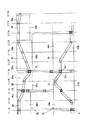
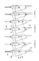
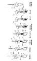
以下に、本発明の最良の形態例を図面に基づいて説明する。図1は本発明に係る被包装物の充填装置を適用した包装機の平面図、図2は同、側面図、図3は充填装置の要部の説明図、図4は間欠回転軸部分を拡大して示す断面図、図5は漏斗用カムと押し棒用カムの展開図、図6は漏斗と押し棒との相対的位置関係を全工程に亘って表した説明図、図7は系外排出工程における押込み動作の説明図、図8は充填工程における押込み動作の説明図、図9は本発明に係る被包装物の充填装置による充填作業の説明図である。 The best mode of the present invention will be described below with reference to the drawings. FIG. 1 is a plan view of a packaging machine to which an apparatus for filling an article according to the present invention is applied. FIG. 2 is a side view of the same. FIG. FIG. 5 is a developed view of the funnel cam and the push rod cam, FIG. 6 is an explanatory diagram showing the relative positional relationship between the funnel and the push rod, and FIG. FIG. 8 is an explanatory view of the pushing operation in the outer discharging process, FIG. 8 is an explanatory view of the pushing operation in the filling process, and FIG.
本発明に係る包装機における被包装物の充填装置10を適用したロータリー方式のガス充填式包装機Pを図1に示す。この包装機Pは、給袋工程(1)、賞味期限等の印字工程(2)、包装袋の開口工程(3)、削り節等の被包装物の充填工程(4)、押込み工程(5)、ノズル挿入及び袋口仮付けシール工程(6)、ガス置換・モミホグシ工程(7)〜(12)、トップシール工程(14)、シール部の冷却工程(15)、製品取出し工程(16)等の16工程からなる。なお、この実施例で取り扱う被包装物については、嵩が大きくて軽くて舞い上がり易い性状の「削り節」である。
FIG. 1 shows a rotary-type gas-filled packaging machine P to which the
この包装機Pの機台1上には、縦向きの間欠回転軸2を回転自由に支持したスタンド3を設けている。その間欠回転軸2に取り付けられた円盤状の回転体4には、給袋工程(1)にて給袋装置6から一枚ずつ供給される包装袋aを掴着又は釈放するための(工程数と同数の)16個のグリップ対gを等角度間隔で放射方向に突出するように設けている。
On the
なお、この実施の形態例では、本発明装置をロータリー方式の包装機Pに適用して説明するが、直線移動方式の包装機に適用することも可能である。
因みに、その直線移動方式の包装機とは、直線部とその両端の半円形部からなる環状通路を水平移動する移動体に多数のグリップ対を直立姿勢及び水平姿勢に変換自在に設け、給袋工程で供給される包装袋を各グリップ対に支持して当該包装袋を開口工程、充填工程、袋口のシール工程等の各工程に間欠停止させて被包装物の袋詰めを行うようにした公知構造のものをいう。
In this embodiment, the apparatus of the present invention is applied to a rotary type packaging machine P, but it can also be applied to a linear movement type packaging machine.
By the way, the linear movement type packaging machine is provided with a large number of grip pairs that can be converted into an upright posture and a horizontal posture on a moving body that horizontally moves in an annular passage composed of a straight portion and semicircular portions at both ends thereof. The packaging bag supplied in the process is supported by each pair of grips, and the packaging bag is intermittently stopped in each process such as the opening process, the filling process, the sealing process of the bag mouth, etc. It has a known structure.
被包装物の充填装置10は、計量手段(図示せず)から被包装物を漏斗へ投入する被包装物の投入工程(21)、外部押し込み装置等を設置可能な工程(22)、計量手段の不具合の場合、計量手段の被包装物を排出させる場合における系外排出工程(23)、押込み工程(24)、充填工程(25)、アイドル工程(26)〜(28)の8工程からなる。
The
機台1上に設置されたスタンド11には、軸受け12a〜12cを介して縦向きの中空の間欠回転軸13を回転自由に設けている(図4)。その間欠回転軸13のフランジ13aに取り付けられた環状回転テーブル15は、インデックス装置とギアとにより構成される公知の図示しない駆動手段により前記回転体4と同期して複数の工程、ここでは8個の工程を間欠回転移動するように設けられている。18は間欠回転軸13の内部に同心状に配置された中軸である。その中軸18の先端に取り付けられた固定テーブル19は、間欠回転軸13に軸受け16a,16bを介して相対的に回転可能に設けられた支持部材17の上端面に固定されている。
A
図3に示すように、回転テーブル15の外周縁には、各工程に対応させて一対のガイドバー20を配置し、各々のガイドバー20に、漏斗23が取り付けられた下部スライド22と、その漏斗23内に投入される削り節を押圧する押し棒26が取り付けられた上部スライド25とをセットにして昇降可能に設けている。それらガイドバー20の上端はリングプレート21に連結されている。各漏斗23の放出口23bには、嘴状の一対の開閉片24を設けている。詳しくは、その開閉片24は、図示しないバネにより放出口23bを閉じるように常に付勢されており、充填工程(25)に配置されたアクチュエータ(図示せず)により一部を押圧されることにより開かれて放出口23bを開放させるように設けられている。また、押し棒26の下端には、先端中央にピン28を備えたほぼ円柱状のブロック27が取り付けられている(図6)。
As shown in FIG. 3, a pair of guide bars 20 are arranged on the outer peripheral edge of the
固定テーブル19には、漏斗用カム31を下方に、押し棒用カム35を上方に配置して縦向きの円筒カム形状に設けている。図5に示すように、漏斗用カム31については、上側カム板32a,33aと下側カム板32b,33bとを一定幅寸法のカム溝34が形成されるように配置している。同様に、押し棒用カム35についても、上側カム板36a,37a,38aと下側カム板36b,37b,38bとを一定幅寸法のカム溝39が形成されるように配置している。そして、下部スライド22の背面側に設けたピン22a(又はカムフォロア)を漏斗用カム31のカム溝34に、上部スライド25に設けたピン25a(又はカムフォロア)を押し棒用カム35のカム溝39に夫々係合可能に設けている。
The fixed table 19 is provided with a funnel cam 31 on the lower side and a
なお、投入工程(21)と充填工程(25)には、漏斗用カム31を設けない。また、系外排出工程(23)と充填工程(25)には、押し棒用カム35を設けない。
The funnel cam 31 is not provided in the charging step (21) and the filling step (25). In addition, the
固定テーブル19上には、被包装物の投入工程(21)に下部スライド22(漏斗23)を昇降自在とする第1昇降手段を、充填工程より前の工程である系外排出工程(23)に上部スライド25(押し棒26)を昇降自在とする第2昇降手段を、充填工程(25)に上部スライド25(押し棒26)を昇降自在とする第3昇降手段45及び下部スライド22(漏斗23)を昇降自在とする第4昇降手段60を夫々設置している。 On the fixed table 19, a first lifting means for allowing the lower slide 22 (funnel 23) to be lifted and lowered in the package loading process (21) is an out-of-system discharge process (23) that is a process prior to the filling process. The second elevating means for allowing the upper slide 25 (push bar 26) to move up and down at the same time, and the third elevating means 45 for allowing the upper slide 25 (push bar 26) to be raised and lowered at the filling step (25) and the lower slide 22 (funnel). The fourth elevating means 60 that allows the elevating and lowering of 23) is provided.
図3に示すように、第3昇降手段45については、固定テーブル19の外周縁に立設した一対のガイドバー46にスライダ50を摺動可能に装着し、そのスライダ50の前面に突設された支持片51によって前記上部スライド25のピン25aを支承可能に設けている。ガイドバー46の上端は、リングプレート47に連結されている。固定テーブル19に設置されたフレーム52には、プーリー53,54を上下に配置して垂直方向に回転自由に設けると共に一方のプーリー53を駆動回転させるサーボモータ装置57を設ける。それらプーリー53,54間に掛け渡されたタイミングベルト55には、スライダ50の後部50bを取り付ける。しかして、サーボモータ装置57によりプーリー53を駆動回転させることによりスライダ50を移動させて前記押し棒26を昇降自在に設ける。
As shown in FIG. 3, the third elevating
第4昇降手段60については、上記ガイドバー46にスライダ61を摺動可能に装着し、そのスライダ61の前面に突設された支持片62によって前記下部スライド22のピン22aを支承可能に設けている。上記フレーム52には、プーリー63,64を上下に配置して垂直方向に回転自由に設けると共に一方のプーリー63を駆動回転させるサーボモータ装置67を設ける。それらプーリー63,64間に掛け渡されたタイミングベルト65には、スライダ61の後部61bを取り付ける。しかして、サーボモータ装置67によりプーリー63を駆動回転させることによりスライダ61を移動させて前記漏斗23を昇降自在に設ける。
As for the fourth elevating
なお、第1昇降手段については、上述した第4昇降手段60と同一構造とされているので、その構造の説明を省略する。図5に示す符号41は、図示しないスライダの支持片である。また、第2昇降手段についても第3昇降手段45と同一構造とされているので、その構造の説明を省略する。同様に、符号43は図示しないスライダの支持片を示す。
The first lifting means has the same structure as the fourth lifting means 60 described above, and the description of the structure is omitted.
漏斗用カム31のカム溝34は、図5に示すように、ほぼ山形形状とされており、押込み工程(24)で最も高い位置に形成されている。そして、押込み工程(24)において、漏斗用カム31と下部スライド22の連係作用により漏斗23を上昇させることにより、漏斗23内の被包装物を圧縮することができるように設けている(請求項3に対応)。
以上により、本発明に係る包装機における被包装物の充填装置10が構成される。
As shown in FIG. 5, the
With the above, the filling
つぎに、本発明に係る包装機における被包装物の充填装置10の作用について説明する。
(1)被包装物の投入工程(21)において、第1昇降手段の作動により漏斗23の上口23aを計量手段の放出口(図示せず)に近接するまで上昇させた状態で当該漏斗23へ100〜150gの被包装物たる削り節kを投入する(図9)。
(2)系外排出工程(23)において、第2昇降手段の作動により押し棒26を複数回押し込むことにより、漏斗23内の削り節kを圧縮して嵩を1/3〜1/5程度とする(図7)。なお、包装機Pの制御部よりn番目のグリップ対gに包装袋が掴着されていない旨の信号が圧縮充填装置10の制御部に入力された場合等には、それに対応すべく投入工程(21)で投入された削り節kを系外へ排出させる。
(3)充填工程(25)において、包装機側の間欠停止した包装袋aの袋口bに、第3昇降手段45と第4昇降手段60の連係作用により漏斗23の下端部を挿入すると同時に開閉片24を開放し、小嵩にされた削り節kを押し棒26により押し込んで充填する(図9)。ついで、押し棒26が1回押し込まれることにより、包装袋a内の削り節kは圧縮されて嵩が小さくなる(図8)。
(4)削り節kが包装袋aに充填されると、押し棒26、漏斗23の順に元の待機位置まで上昇し、漏斗23の開閉片24,24が閉じられる(図9)。
以後、上記(1)〜(4)の一連の作用が繰り返されることにより、充填工程(25)に間欠的に送り込まれる包装袋aに削り節kが順次充填される。
Next, the operation of the filling
(1) In the charging step (21) of the article to be packaged, the
(2) In the out-of-system discharge step (23), the
(3) In the filling step (25), at the same time as inserting the lower end of the
(4) When the shaving k is filled in the packaging bag a, the
Thereafter, the series of actions (1) to (4) is repeated, so that the cut k is sequentially filled into the packaging bag a intermittently fed into the filling step (25).
なお、包装機Pのグリップ対gに供給された包装袋aが被包装物の充填工程(4)までの間に開口ミス等が生じた場合、充填装置10側では該包装袋に対して充填を行わず、漏斗23をそのまま回転移動させて再び充填工程(25)に移動したときに別の包装袋に充填を施すように構成されている。
If an opening error or the like occurs in the packaging bag a supplied to the grip pair g of the packaging machine P until the filling step (4) of the package, the filling
以上に述べた通り、この包装機における被包装物の充填装置は、被包装物の漏斗への投入動作と包装袋への充填動作を2段階に分けて行うことにより、処理能力が従来の毎分15〜18袋から毎分30袋程度まで向上する等の利点を有する。 As described above, the filling device for a package in this packaging machine performs processing operation in a conventional manner by performing the operation of charging the package into the funnel and filling the packaging bag in two stages. It has the advantage of improving from 15 to 18 bags per minute to about 30 bags per minute.
P・・・ガス充填式包装機
g・・・グリップ対
a・・・包装袋 b・・・袋口
k・・・削り節(被包装物)
10・・・本発明に係る被包装物の充填装置
13・・・間欠回転軸
15・・・回転テーブル
18・・・中軸
19・・・固定テーブル
20・・・ガイドバー
22・・・下部スライド
22a・・・ピン
23・・・漏斗
25・・・上部スライド
25a・・・ピン
26・・・押し棒
31・・・漏斗用カム
34・・・カム溝
35・・・押し棒用カム
39・・・カム溝
45・・・第3昇降手段
46・・・ガイドバー
50・・・スライダ
51・・・支持片
57・・・サーボモータ装置
60・・・第4昇降手段
61・・・スライダ
62・・・支持片
67・・・サーボモータ装置
P: Gas filling type packaging machine g: Grip pair a: Packaging bag b ... Bag mouth k: Sharpening (packaged item)
DESCRIPTION OF
Claims (3)
前記充填装置は、縦向きの間欠回転軸に取り付けた環状回転テーブルを駆動手段により前記移動体と同期して複数の工程を回転移動するように設け、その回転テーブルに各工程に対応させて配置された各々のガイドバーに、放出口を開閉片により開閉自在に設けた漏斗が取り付けられた下部スライドと、その漏斗内に投入される被包装物を押圧する押し棒が取り付けられた上部スライドを昇降可能に設け、前記間欠回転軸内に同心状に配置された中軸に取り付けた固定テーブルに、漏斗用カムを下方に押し棒用カムを上方に配置して縦向きの円筒カム形状に設け、前記下部スライドに設けたピンを漏斗用カムのカム溝に、前記上部スライドに設けたピンを押し棒用カムのカム溝に夫々係合可能に設け、被包装物の投入工程にて前記下部スライドを昇降自在とする第1昇降手段と、充填工程より前の工程にて前記上部スライドを昇降自在とする第2昇降手段と、充填工程にて前記上部スライドを昇降自在とする第3昇降手段及び前記下部スライドを昇降自在とする第4昇降手段とを前記固定テーブルに夫々設置してなり、
被包装物の投入工程にて第1昇降手段の作動により前記漏斗の上口を計量手段の放出口に近接するまで上昇させた状態で当該漏斗へ被包装物を投入し、充填工程より前の工程にて第2昇降手段の作動により漏斗内の被包装物を前記押し棒により少なくとも1回圧縮して嵩を小さくした状態とし、充填工程にて間欠停止した包装袋の袋口に第3昇降手段と第4昇降手段の連係作用により前記漏斗の下端部を挿入すると同時に前記開閉片を開放して小嵩にされた被包装物を前記押し棒により押し込んで充填し、さらに、その押し棒により該被包装物を少なくとも1回圧縮するように設けたことを特徴とする包装機における被包装物の充填装置。 A movable body having one or many grip pairs is intermittently stopped and moved in a number of steps, and a predetermined amount of a compressible package is placed in a packaging bag supported in a suspended manner by each grip pair by a filling device. In a packaging machine configured to seal the bag mouth after filling,
The filling device is provided with an annular rotary table attached to a vertical intermittent rotary shaft so as to rotate and move a plurality of processes in synchronization with the moving body by a driving means, and arranged on the rotary table corresponding to each process. Each guide bar is provided with a lower slide to which a funnel having a discharge port that can be freely opened and closed by an opening and closing piece, and an upper slide to which a push rod that presses an object to be packaged is inserted. Provided to be able to move up and down, on a fixed table attached to the central shaft concentrically arranged in the intermittent rotation shaft, push the funnel cam downward and the cam for the rod upward to provide a vertical cylindrical cam shape, The pin provided on the lower slide is provided in the cam groove of the funnel cam, and the pin provided on the upper slide is provided in the cam groove of the push rod cam so that they can be engaged. First elevating means for allowing the upper slide to move up and down, second elevating means for allowing the upper slide to move up and down in a process prior to the filling process, third elevating means for allowing the upper slide to move up and down in the filling process, and A fourth elevating means for allowing the lower slide to move up and down is installed on each of the fixed tables;
In the charging process, the packaging material is charged into the funnel in a state where the top of the funnel is raised by the operation of the first lifting / lowering means in the vicinity of the discharge port of the weighing means. In the process, the package in the funnel is compressed at least once by the push rod by the operation of the second lifting / lowering means to reduce the bulk, and the third lifting / lowering is performed on the bag mouth of the packaging bag intermittently stopped in the filling process. The lower end portion of the funnel is inserted by the cooperative action of the means and the fourth elevating means, and at the same time the opening and closing pieces are opened and the packaged material which is made small is pushed and filled by the push rod, and further, by the push rod An apparatus for filling an article to be packaged in a packaging machine, wherein the article to be packaged is provided to be compressed at least once.
Priority Applications (1)
| Application Number | Priority Date | Filing Date | Title |
|---|---|---|---|
| JP2007235244A JP5044846B2 (en) | 2007-09-11 | 2007-09-11 | Packing device for packing material in packaging machine |
Applications Claiming Priority (1)
| Application Number | Priority Date | Filing Date | Title |
|---|---|---|---|
| JP2007235244A JP5044846B2 (en) | 2007-09-11 | 2007-09-11 | Packing device for packing material in packaging machine |
Publications (2)
| Publication Number | Publication Date |
|---|---|
| JP2009067405A JP2009067405A (en) | 2009-04-02 |
| JP5044846B2 true JP5044846B2 (en) | 2012-10-10 |
Family
ID=40604092
Family Applications (1)
| Application Number | Title | Priority Date | Filing Date |
|---|---|---|---|
| JP2007235244A Active JP5044846B2 (en) | 2007-09-11 | 2007-09-11 | Packing device for packing material in packaging machine |
Country Status (1)
| Country | Link |
|---|---|
| JP (1) | JP5044846B2 (en) |
Families Citing this family (6)
| Publication number | Priority date | Publication date | Assignee | Title |
|---|---|---|---|---|
| JP5602451B2 (en) * | 2010-02-17 | 2014-10-08 | 不双産業株式会社 | Bag making and filling equipment |
| JP5576148B2 (en) * | 2010-03-03 | 2014-08-20 | 東洋自動機株式会社 | Package filling equipment for vertical bag filling and packaging machine |
| JP6019323B2 (en) * | 2011-06-20 | 2016-11-02 | ゼネラルパッカー株式会社 | Compressed filling method for packaged items |
| GB201121384D0 (en) * | 2011-12-13 | 2012-01-25 | Ishida Europ Ltd | Tamping system and method |
| JP6667206B2 (en) * | 2015-03-30 | 2020-03-18 | 株式会社古川製作所 | Packing device and packing device |
| JP2019038585A (en) * | 2017-08-25 | 2019-03-14 | 東洋自動機株式会社 | Throwing-in device |
Family Cites Families (2)
| Publication number | Priority date | Publication date | Assignee | Title |
|---|---|---|---|---|
| JPS58171801U (en) * | 1982-05-11 | 1983-11-16 | 株式会社石田衡器製作所 | Goods supply device |
| JP4543231B2 (en) * | 2004-06-28 | 2010-09-15 | ゼネラルパッカー株式会社 | Gas filling and packaging machine for double pack bags |
-
2007
- 2007-09-11 JP JP2007235244A patent/JP5044846B2/en active Active
Also Published As
| Publication number | Publication date |
|---|---|
| JP2009067405A (en) | 2009-04-02 |
Similar Documents
| Publication | Publication Date | Title |
|---|---|---|
| JP5044846B2 (en) | Packing device for packing material in packaging machine | |
| CN108557165B (en) | Energy-saving environment-friendly full-automatic canned tea packing machine | |
| CN106005593A (en) | Foam box sealing packer and packing method thereof | |
| CN206939231U (en) | A kind of blanking device of sealing machine | |
| JP2008007139A (en) | Compression filling packaging method | |
| JP5050204B2 (en) | Packing machine filling equipment | |
| CN208291610U (en) | One production of soap packing hoisting mechanism | |
| CN208291595U (en) | Bag-feeding type package machine | |
| CN108190101B (en) | Assembly boxing device | |
| CN202449235U (en) | Granular material packaging machine | |
| WO2013051950A1 (en) | Packaging apparatus | |
| CN112793824A (en) | Be used for bread sealing equipment | |
| JP5044847B2 (en) | Packing machine filling equipment | |
| CN218463968U (en) | Guide rail bag clamping mechanism on vacuum packaging machine | |
| JP2884061B2 (en) | Packaging machine | |
| JP3559483B2 (en) | Quantitative filling method for packaged objects in packaging machine | |
| CN111252281A (en) | Food packaging method and packaging equipment thereof | |
| CN213292831U (en) | Material bagging apparatus side by side | |
| JP3696704B2 (en) | Packing machine filling equipment | |
| CN210175242U (en) | Updraft type bag feeding machine capable of automatically feeding bags | |
| CN112109965A (en) | Parallel bagging mode for materials | |
| CN112918786A (en) | Full-automatic bag feeding and packaging device | |
| CN219565564U (en) | Part boxing and sealing equipment | |
| JP6019323B2 (en) | Compressed filling method for packaged items | |
| JP4639369B2 (en) | Compressed filling method for packaged items |
Legal Events
| Date | Code | Title | Description |
|---|---|---|---|
| A621 | Written request for application examination |
Free format text: JAPANESE INTERMEDIATE CODE: A621 Effective date: 20100818 |
|
| A977 | Report on retrieval |
Free format text: JAPANESE INTERMEDIATE CODE: A971007 Effective date: 20120531 |
|
| TRDD | Decision of grant or rejection written | ||
| A01 | Written decision to grant a patent or to grant a registration (utility model) |
Free format text: JAPANESE INTERMEDIATE CODE: A01 Effective date: 20120612 |
|
| A01 | Written decision to grant a patent or to grant a registration (utility model) |
Free format text: JAPANESE INTERMEDIATE CODE: A01 |
|
| A61 | First payment of annual fees (during grant procedure) |
Free format text: JAPANESE INTERMEDIATE CODE: A61 Effective date: 20120628 |
|
| FPAY | Renewal fee payment (event date is renewal date of database) |
Free format text: PAYMENT UNTIL: 20150727 Year of fee payment: 3 |
|
| R150 | Certificate of patent or registration of utility model |
Ref document number: 5044846 Country of ref document: JP Free format text: JAPANESE INTERMEDIATE CODE: R150 Free format text: JAPANESE INTERMEDIATE CODE: R150 |
|
| R250 | Receipt of annual fees |
Free format text: JAPANESE INTERMEDIATE CODE: R250 |
|
| R250 | Receipt of annual fees |
Free format text: JAPANESE INTERMEDIATE CODE: R250 |
|
| R250 | Receipt of annual fees |
Free format text: JAPANESE INTERMEDIATE CODE: R250 |
|
| R250 | Receipt of annual fees |
Free format text: JAPANESE INTERMEDIATE CODE: R250 |
|
| R250 | Receipt of annual fees |
Free format text: JAPANESE INTERMEDIATE CODE: R250 |
|
| R250 | Receipt of annual fees |
Free format text: JAPANESE INTERMEDIATE CODE: R250 |
|
| R250 | Receipt of annual fees |
Free format text: JAPANESE INTERMEDIATE CODE: R250 |
|
| R250 | Receipt of annual fees |
Free format text: JAPANESE INTERMEDIATE CODE: R250 |
|
| R250 | Receipt of annual fees |
Free format text: JAPANESE INTERMEDIATE CODE: R250 |