JP5040904B2 - Check valve - Google Patents
Check valve Download PDFInfo
- Publication number
- JP5040904B2 JP5040904B2 JP2008325328A JP2008325328A JP5040904B2 JP 5040904 B2 JP5040904 B2 JP 5040904B2 JP 2008325328 A JP2008325328 A JP 2008325328A JP 2008325328 A JP2008325328 A JP 2008325328A JP 5040904 B2 JP5040904 B2 JP 5040904B2
- Authority
- JP
- Japan
- Prior art keywords
- closing
- outlet
- check valve
- valve plate
- passage
- Prior art date
- Legal status (The legal status is an assumption and is not a legal conclusion. Google has not performed a legal analysis and makes no representation as to the accuracy of the status listed.)
- Expired - Fee Related
Links
Images


Landscapes
- Cooling, Air Intake And Gas Exhaust, And Fuel Tank Arrangements In Propulsion Units (AREA)
- Check Valves (AREA)
Description
本発明は、車両の燃料タンクに燃料を導入するための給油管などに装着される逆止弁に関する。 The present invention relates to a check valve attached to a fuel supply pipe for introducing fuel into a fuel tank of a vehicle.
従来、自動車の燃料タンクには、給油のストップ時に、上昇したタンク内圧により、インレットパイプから燃料が外部に流出するのを防止するための逆止弁を備えたものが知られている(例えば、特許文献1参照)。逆止弁は、通路から燃料を流出する流出口を備えた通路形成部材と、該通路形成部材に取り付けられ流出口を開閉する弁プレートとを備えている。弁プレートは、閉止部の一端部に被取付部を折曲形成し、この被取付部を通路形成部材の外周部に形成された取付部に取り付けることにより、閉止部で流出口を開閉している。 2. Description of the Related Art Conventionally, a fuel tank of an automobile includes a check valve for preventing fuel from flowing out from an inlet pipe due to an increased tank internal pressure when refueling is stopped (for example, Patent Document 1). The check valve includes a passage forming member having an outflow port through which fuel flows out from the passage, and a valve plate attached to the passage forming member to open and close the outflow port. The valve plate is formed by bending the attached portion at one end of the closing portion, and attaching the attached portion to the attaching portion formed on the outer peripheral portion of the passage forming member, thereby opening and closing the outlet at the closing portion. Yes.
従来の逆止弁は、閉弁状態にて厳密なシール性を求めていないために、燃料タンクに燃料が満タン付近まで満たされている場合に、通路形成部材内に燃料が溜まっている。こうした通路形成部材内の燃料は、車両が急発進したり、段差路を走行した際に、揺動して弁プレートを押して開閉させる。このような弁プレートの閉じ動作は、乗員にとって耳障りな異音を発生することがあった。 Since the conventional check valve does not require a strict sealing property in the closed state, the fuel is accumulated in the passage forming member when the fuel tank is filled to the vicinity of the full tank. The fuel in the passage forming member swings and pushes and opens and closes the valve plate when the vehicle starts suddenly or travels on a step road. Such a closing operation of the valve plate may generate an abnormal noise that is annoying to the occupant.
本発明は、上記従来の技術の問題点を解決することを踏まえ、流出口を開閉する弁プレートの閉止部が閉まるときの耳障りな異音を防止する手段を、簡単な構成で部品点数を増やすことなく実現することができる逆止弁を提供することを目的とする。 The present invention is based on solving the above-described problems of the prior art, and increases the number of parts with a simple structure as a means for preventing annoying noise when the valve plate closing portion that opens and closes the outlet is closed. An object of the present invention is to provide a check valve that can be realized without any problems.
本発明は、上述の課題の少なくとも一部を解決するためになされたものであり、以下の形態または適用例として実現することが可能である。 SUMMARY An advantage of some aspects of the invention is to solve at least a part of the problems described above, and the invention can be implemented as the following forms or application examples.
[適用例1]
適用例1は、通路および該通路から流体を流出する流出口を備えた通路形成部材と、弾性を有する薄板を切断および折曲することにより形成され上記流出口を開閉する弁プレートとを備えた逆止弁において、
上記通路形成部材は、上記弁プレートを取り付けるための取付部と、上記流出口の開口周縁部に形成されたシート面と、該シート面に突設されたシート段部とを備え、
上記弁プレートは、上記流出口を開閉する閉止部と、該閉止部の外周部から折曲形成され上記取付部に取り付けるための被取付部とを備え、上記閉止部が上記流体で押されたときに上記被取付部を支点として傾くことにより流出口を開くように構成され、
さらに、上記閉止部の外周部の一部は、上記閉止部の閉じ状態にて、上記シート段部に当たる接触部を有し、該接触部は、上記閉止部の外周部が上記シート面に当たる接触面積を低減するように構成したこと、を特徴とする。
[Application Example 1]
Application Example 1 includes a passage forming member including a passage and an outflow port through which a fluid flows out from the passage, and a valve plate formed by cutting and bending an elastic thin plate and opening and closing the outflow port. In the check valve,
The passage forming member includes an attachment portion for attaching the valve plate, a seat surface formed at an opening peripheral edge portion of the outlet, and a seat step portion protruding from the seat surface,
The valve plate includes a closing portion that opens and closes the outlet, and a mounted portion that is bent from an outer peripheral portion of the closing portion and is attached to the mounting portion, and the closing portion is pushed by the fluid Sometimes it is configured to open the outlet by tilting the mounted part as a fulcrum,
Further, a part of the outer peripheral portion of the closing portion has a contact portion that hits the seat step portion in the closed state of the closing portion, and the contact portion is a contact that the outer peripheral portion of the closing portion hits the seat surface. It is configured to reduce the area.
適用例1に記載の逆止弁において、通路形成部材に形成された通路の流出口を弁プレートで開閉する。弁プレートは、弾性を有する薄板を用いて、閉止部および閉止部の外周の一部から折曲された被取付部を一体的に形成し、被取付部で通路形成部材の取付部に取り付けられている。被取付部は、閉止部をシート部に着座させる方向へ付勢力を与えるばねとして作用し、閉止部に流体の力が加わったときに、閉止部との連結部位を支点として傾斜することで閉止部を開き動作させる。そして、閉止部の開き動作により、燃料が燃料タンクに流出する。そして、閉止部を押す燃料の力が、閉止部に加わっている閉弁方向の力を下回ると、閉止部が流出口を閉じる。 In the check valve described in Application Example 1, the outlet of the passage formed in the passage forming member is opened and closed with a valve plate. The valve plate uses an elastic thin plate to integrally form the closed portion and the attached portion bent from a part of the outer periphery of the closed portion, and the attached portion is attached to the attachment portion of the passage forming member. ing. The mounted portion acts as a spring that applies a biasing force in the direction in which the closing portion is seated on the seat portion, and when a fluid force is applied to the closing portion, the attached portion is closed by tilting with a connection portion with the closing portion as a fulcrum. Open the part and operate. Then, the fuel flows out to the fuel tank by the opening operation of the closing portion. And if the force of the fuel which pushes a closing part falls below the force of the valve closing direction which has applied to the closing part, a closing part will close an outflow port.
ここで、燃料タンクに燃料が満タン付近まで満たされ、通路形成部材内に燃料が溜まっている状態にあるとする。こうした状態において、車両が急発進したり、段差路を走行して、通路形成部材内の燃料が揺動して、弁プレートを押して開閉したときに、閉止部と一体形成された接触部がシート段部に当たる。接触部がシート段部に当たると、接触部を除いた閉止部の外周部と流出口の開口周縁部とが衝突する面積が減少するとともに、閉止部とシート面との間に僅かに隙間を生じる。このため、衝突する面積の減少および隙間により、閉止部の開閉に伴う衝突音が低減するとともに、通路形成部材の通路の共鳴がなくなり、乗員に耳障りな異音をなくせる。なお、逆止弁は、給油時における燃料の吹き返しを防止することを主目的としているから、閉止部とシート面との間に高いシール性を必要としない。 Here, it is assumed that the fuel is filled in the fuel tank to the vicinity of the full tank and the fuel is accumulated in the passage forming member. In such a state, when the vehicle starts suddenly or travels on a step road, the fuel in the passage forming member swings and pushes the valve plate to open and close, the contact portion formed integrally with the closing portion is the seat. Hit the step. When the contact portion hits the sheet step portion, the area where the outer peripheral portion of the closing portion excluding the contact portion collides with the opening peripheral edge portion of the outflow port is reduced, and a slight gap is generated between the closing portion and the seat surface. . For this reason, due to the reduction of the collision area and the gap, the collision noise associated with the opening and closing of the closing portion is reduced, the resonance of the passage of the passage forming member is eliminated, and the annoying noise that is annoying to the passenger can be eliminated. The check valve mainly aims to prevent the fuel from blowing back during refueling, and therefore does not require high sealing performance between the closing portion and the seat surface.
また、逆止弁による異音を防止する構成は、弁プレートの閉止部の外周部に形成された接触部および通路形成部材から突設されたシート段部であるから、部品点数が増加することもなく、構成が簡単である。 Further, the structure for preventing abnormal noise due to the check valve is the contact step formed on the outer peripheral portion of the closing portion of the valve plate and the seat step portion protruding from the passage forming member, so that the number of parts increases. There is no configuration.
[適用例2]
適用例2に記載の逆止弁にかかる閉止部は、ほぼ円板状に形成され、上記接触部は、上記閉止部の中心に対して上記取付部と反対側に突設されている構成である。
[Application Example 2]
The closing portion of the check valve described in Application Example 2 is formed in a substantially disc shape, and the contact portion protrudes on the opposite side of the mounting portion with respect to the center of the closing portion. is there.
[適用例3]
適用例3の接触部は、上記閉止部の外周部から突設されている構成である。
[Application Example 3]
The contact part of the application example 3 is configured to protrude from the outer peripheral part of the closing part.
[適用例4]
適用例4は、通路および該通路から流体を流出する流出口を備えた通路形成部材と、弾性を有する薄板を切断および折曲することにより形成され上記流出口を開閉する弁プレートとを備えた逆止弁において、
上記通路形成部材は、上記弁プレートを取り付けるための取付部と、上記流出口の開口周縁部に形成されたシート面とを備え、
上記弁プレートは、上記流出口を開閉する閉止部と、該閉止部の外周部から折曲形成され上記取付部に取り付けるための被取付部と、上記閉止部の外周部の一部から流出口側へ折曲された接触部と、を備え、
上記閉止部が上記流体で押されたときに上記被取付部を支点として傾くことにより流出口を開くように構成され、さらに、上記閉止部の閉じ状態にて、上記接触部が上記シート面に当たることで、上記閉止部の外周部が上記シート面に当たる接触面積を低減するように形成したこと、を特徴とする。この構成のように、閉止部の外周部が全周で当たるのを回避するための構成として、閉止弁の外周部に接触部を突設してもよい。
[Application Example 4]
Application Example 4 includes a passage forming member including a passage and an outflow port through which a fluid flows out from the passage, and a valve plate formed by cutting and bending an elastic thin plate and opening and closing the outflow port. In the check valve,
The passage forming member includes an attachment portion for attaching the valve plate, and a seat surface formed on an opening peripheral edge portion of the outlet.
The valve plate includes a closing portion that opens and closes the outlet, a mounted portion that is bent from the outer peripheral portion of the closing portion and is attached to the mounting portion, and an outlet from a part of the outer peripheral portion of the closing portion. A contact portion bent to the side,
When the closing part is pushed by the fluid, the outlet is opened by tilting with the attached part as a fulcrum, and the contact part hits the seat surface in the closed state of the closing part. Thus, the outer peripheral portion of the closing portion is formed so as to reduce a contact area where it hits the seat surface. As a configuration for avoiding the outer peripheral portion of the closing portion from hitting the entire periphery as in this configuration, a contact portion may be provided to protrude from the outer peripheral portion of the closing valve.
(1) 給油装置FSの概略構成
図1は自動車の燃料タンクFTに燃料を供給するための給油装置FSを示す概略図である。図1に示すように、給油装置FSは、燃料タンクFTに接続され、給油ガン(図示省略)から供給される燃料を燃料タンクFTに送るものであり、燃料キャップFCにより開閉される注入口を有するフィラーネックFNと、フィラーネックFNの一端に接続され金属製または樹脂製のインレットパイプIPと、インレットパイプIPに接続されゴム製のインレットホースHと、インレットホースHの一端に接続されかつ燃料タンクFTに溶着された燃料タンク用管接続体10と、燃料タンク用管接続体10に装着された逆止弁20を備えている。インレットホースHは、燃料タンク用管接続体10に圧入されるとともにクランプCPにより締結されている。なお、フィラーネックFNには、図示しないブリーザパイプが燃料タンクFTに接続されている。上記給油装置FSの構成により、給油時に燃料キャップFCを外して、給油ガンから燃料をフィラーネックFNに注入すると、燃料は、インレットパイプIP、インレットホースH、燃料タンク用管接続体10を流れて、さらに逆止弁20を開いて燃料タンクFT内に供給される。一方、給油ストップ時では、逆止弁20は、閉弁状態にあるから、上昇したタンク内圧により燃料が押し戻されて外部へ流出するのを防止する。
(1) Schematic Configuration of Refueling Device FS FIG. 1 is a schematic view showing a fueling device FS for supplying fuel to a fuel tank FT of an automobile. As shown in FIG. 1, the fueling device FS is connected to a fuel tank FT and sends fuel supplied from a fueling gun (not shown) to the fuel tank FT, and has an inlet that is opened and closed by a fuel cap FC. A filler neck FN, a metal or resin inlet pipe IP connected to one end of the filler neck FN, a rubber inlet hose H connected to the inlet pipe IP, and a fuel tank connected to one end of the inlet hose H A fuel
(2) 各部の構成および作用
以下、各部の構成について説明する。
(2)−1 燃料タンクFT
燃料タンクFTは、耐燃料透過性に優れたエチレンビニルアルコール共重合体(EVOH)から形成されたバリア層と、ポリエチレン(PE)で形成された外層とを含む複数の樹脂層から形成されている。燃料タンクFTの側壁の上部には、タンク開口FTaが形成されており、このタンク開口FTaを囲むように燃料タンク用管接続体10が溶着されている。
(2) Configuration and operation of each unit The configuration of each unit will be described below.
(2) -1 Fuel tank FT
The fuel tank FT is formed of a plurality of resin layers including a barrier layer formed of an ethylene vinyl alcohol copolymer (EVOH) excellent in fuel permeation resistance and an outer layer formed of polyethylene (PE). . A tank opening FTa is formed in the upper part of the side wall of the fuel tank FT, and a fuel
(2)−2 燃料タンク用管接続体10
図2は燃料タンクFTの燃料タンク用管接続体10および逆止弁20を拡大した断面図である。燃料タンク用管接続体10は、通路形成部12と、接続用溶着部14とを備え、これらを2色成形により一体に形成している。通路形成部12は、インレットホースHに接続される通路を形成する通路部12aを備えている。通路部12aの一端は、該通路部12aの外周端から拡張されることでインレットホースH(図1)を抜止するための抜止拡張部12bになっている。通路部12aの他端には、フランジ12cが形成されている。フランジ12cの一方の面は、接続用溶着部14に内壁に溶着される面になっており、その他面は、逆止弁20の一端を溶着するための溶着部12dになっている。通路形成部12は、例えば、ナイロン−12などのポリアミド(PA)から形成されている。接続用溶着部14は、外筒部14aと、外筒部14aの一端外周から拡張されたフランジ14bと、フランジ14bの一端面に環状に突設された溶着端14cとを備えている。接続用溶着部14は燃料タンクFTに熱溶着可能である変性ポリエチレンから形成されている。変性ポリエチレンは、ポリエチレン(PE)に極性官能基、例えばマレイン酸変性された官能基を付加した樹脂材料であり、PAと射出成型時の熱により反応接着する材料である。よって、接続用溶着部14は、2色成形により通路形成部12と反応接着により溶着一体化している。
(2) -2
FIG. 2 is an enlarged cross-sectional view of the fuel
(2)−3 逆止弁20の構成
逆止弁20は、筒状の通路形成部材22と、この通路形成部材22の一端に装着されかつ流出口23aを開閉する弁プレート30とを備えている。通路形成部材22は、通路形成部12と同じPAから形成された筒形状であり、その内部にインレットホースHに接続される通路22aを有し、そのインレットホースH側が流入口23bになっている。通路形成部材22の流入口23bの端部には、フランジ25を有し、通路形成部12の溶着部12dに溶着により一体になって流路を形成している。
(2) -3 Configuration of
図3は通路形成部材22に弁プレート30を組み付ける前の状態を拡大して示す断面図である。通路形成部材22の流出口23aの外周縁部に沿って、弁プレート30が着離するシート面26aがほぼ環状に形成されている。シート面26aの下半円の外周部を囲むように、シート段部26bが形成されている。また、通路形成部材22の流出口23aの外周部には、弁プレート30を取り付けるための取付部27が突設されている。なお、取付部27の構成については、後述する。
FIG. 3 is an enlarged sectional view showing a state before the
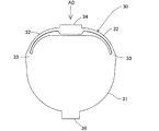
図4は弁プレート30を通路形成部材22から外した状態を示す斜視図、図5は弁プレート30の付近を示す断面図、図6は弁プレート30を示す平面図、図7は図6の矢印ADから見た図である。弁プレート30は、金属製の薄板をプレス切断して折曲することにより、閉止部31、アーム部32,32、連結部33,33、被取付部34および接触部36を一体的に板ばねとして形成したものである。
4 is a perspective view showing a state in which the
上記閉止部31は、シート面26aの外形とほぼ同一の形状であり、通路形成部材22の流出口23aを開閉するものであり、つまりシート面26aに着離するように形成されている。アーム部32,32は、閉止部31の外周部のほぼ半円を囲むように形成されている。アーム部32,32の一端部の各々は、連結部33,33を介して閉止部31にそれぞれ連結され、他端部の各々は、被取付部34により連結されている。被取付部34は、通路形成部材22の取付部27に挿入されることにより、閉止部31を開閉可能に支持する部位であり、閉止部31に対して折曲されている。図3に示すように、被取付部34は、閉止部31に対してなす角度をα、通路形成部材22の流出口23aの開口周縁部の角度をβとすると、10≦β−α≦20゜の範囲となるように折曲されている。これは、角度(β−α)が20゜より大きいと、閉止部31がシート面26aに押圧する力が大きくなり、所定以上の燃料の流出量を確保することができないからであり、一方、10゜より小さいと、閉止部31が閉じる力が小さくなるからである。
The closing
図8は通路形成部材22の取付部27および弁プレート30の被取付部34の付近を拡大した断面図である。図4および図8に示すように、取付部27は、通路形成部材22の外周部からほぼ平行に立設された側壁部27a,27aを備えている。各々の側壁部27aは、立壁27bと、この立壁27bの上端から互いに向き合うように延設された押さえ部27cとを備え、立壁27bと押さえ部27cとにより断面L字形に形成されている。また、押さえ部27c,27cにまたがってブリッジ部27dが形成されている。また、側壁部27a,27aの間は、被取付部34を収納するための取付溝28となっている。取付溝28の底には、挿入口28aから奥側に向けて上方へ傾斜した傾斜面28bが形成され、被取付部34の挿入作業性を高めている。また、傾斜面28bの一端から凹所に形成された係合部28cが形成されている。
FIG. 8 is an enlarged cross-sectional view of the vicinity of the
一方、弁プレート30の被取付部34は、矩形の本体板34aと、抜止部34bと、弾性片34cとを備えている。抜止部34bおよび弾性片34cは、本体板34aから約45゜でプレス成形などで切り起こされることにより形成されている。抜止部34bは、係合部28cに係合することにより被取付部34を取付部27からの抜止めの作用を果たし、また、弾性片34cは、押さえ部27cと取付溝28との溝底とで圧縮することにより径方向へのガタツキを抑制している。
On the other hand, the attached
弁プレート30の被取付部34を通路形成部材22の取付部27に取り付けるには、被取付部34を傾斜面28bに沿わせつつ挿入口28aへ挿入する。抜止部34bおよび弾性片34cがブリッジ部27dと取付溝28の溝底との間で圧縮されつつ、被取付部34が取付溝28の奥側へ挿入される。抜止部34bが係合部28cに達して弾性力により係合部28cに挿入されることで被取付部34が取付部27に固定される。
In order to attach the attached
図4ないし図6において、逆止弁20は、弁プレート30の閉止部31が流出口23aを閉じるときの異音を防止するための異音防止手段を備えている。異音防止手段は、通路形成部材22の流出口23aの開口周縁部に形成されたシート段部26bと、弁プレート30の下部に矩形に突設された接触部36とから構成されている。接触部36は、弁プレート30が閉まったときに、シート段部26bに当たって、閉止部31とともに湾曲することで、閉止部31の外周部がシート面26aに当たる面積を減らすとともに、シート面26aとの間に僅かな間隙を確保している。シート段部26bは、閉止部31の外周部の下半分を囲むことで、取扱作業者によって不用意に引っ掛けて、弁プレート30を塑性変形させてしまい、閉じなくなるのを防止するシート保護段部としての効果も奏する。
4 to 6, the
(2)−4 逆止弁20の動作
次に、逆止弁20の動作について説明する。図9に示すように、給油時に、通路形成部材22の流入口23bから入った燃料は、通路22aを通って流出口23aに達し、弁プレート30の閉止部31を押す。弁プレート30は、被取付部34で通路形成部材22の取付部27に取り付けられているから、被取付部34を支点として開弁する。すなわち、燃料により閉止部31が押されると、閉止部31は、連結部33,33を中心にアーム部32,32に対して傾斜して、流出口23aとの間に流路を形成し、燃料が流出する。そして、閉止部31を押す燃料の力が、閉止部31に加わっている閉弁方向の力を下回ると、閉止部31が閉じる。
(2) -4 Operation of
(3) 上記実施例による逆止弁20によれば、以下の作用・効果を得ることができる。
(3)−1 燃料タンクに燃料が満タン付近まで満たされ、通路形成部材内に燃料が溜まっている状態にあるとする。こうした状態において、車両が急発進したり、段差路を走行して、通路形成部材22内の燃料が揺動して、弁プレート30を押して開閉したときに、図5に示すように、閉止部31と一体形成された接触部36がシート段部26bに当たる。接触部36がシート段部26bに当たると、接触部36を除いた閉止部31の外周部と流出口23aの開口周縁部とが衝突する面積が減少するとともに、閉止部31とシート面26aとの間に僅かに隙間を生じる。このため、衝突する面積の減少および隙間により、閉止部31の開閉に伴う衝突音が低減するとともに、通路形成部材22の通路22aの共鳴がなくなり、乗員に耳障りな異音をなくせる。なお、逆止弁は、給油時における燃料の吹き返しを防止することを主目的としているから、閉止部31とシート面26aとの間に高いシール性を必要としない。
(3) According to the
(3) -1 It is assumed that the fuel tank is filled with fuel up to the vicinity of the full tank and the fuel is accumulated in the passage forming member. In such a state, when the vehicle starts suddenly or travels on a step road, the fuel in the
(3)−2 逆止弁20による異音を防止する構成は、弁プレート30の閉止部31の外周部に形成された接触部36および通路形成部材22から突設されたシート段部26bであるから、部品点数が増加することもなく、構成が簡単である。
(3) -2 The structure for preventing the abnormal noise caused by the
(4) 他の実施例
この発明は上記実施例に限られるものではなく、その要旨を逸脱しない範囲において種々の態様において実施することが可能であり、例えば次のような変形も可能である。
(4) Other Embodiments The present invention is not limited to the above-described embodiments, and can be implemented in various modes without departing from the gist thereof. For example, the following modifications are possible.
(4)−1 図10は他の実施例にかかる逆止弁20Bを分解した斜視図である。本実施例は、異音防止手段として、通路形成部材22Bのシート面26Baにシート段部26Bbを形成するとともに、シート段部26Bbに閉止部31Bの外周下部の接触部36Bが当たる構成に特徴を有する。すなわち、シート面26Baの内周下部に、シート段部26Bbが形成され、さらに外周半周部にシート保護段部26Bcが形成されている。シート保護段部26Bcは、上述したように、引っ掛けによる弁プレート30Bの塑性変形を防止するものであり、上述の実施例と異なり、シート段部26Bbと分離して形成されている。本実施例において、閉止状態において、閉止部31Bの外周下部の接触部36Bが、シート段部26Bbに当たることで、閉止部31Bの全外周部がシート面26Baに衝突するのを避けて耳障りな異音をなくしている。
(4) -1 FIG. 10 is an exploded perspective view of a
(4)−2 図11はさらに他の実施例にかかる逆止弁20Cを示す断面図である。本実施例は、異音防止手段として、弁プレート30Cの閉止部31Cの下端に接触部36Cを折曲形成した構成に特徴を有する。すなわち、接触部36Cは、閉止部31Cの外周下部の一部を切り起こして接触部36Cの下端の脚部36Caでシート面26Caに当たるようにした構成である。また、弁プレート30Cの塑性変形を防止するためのシート保護段部26Ccが接触部36Cも保護するように、閉止状態における閉止部31Cの下端より高くなるように形成されている。本実施例において、接触部36Cの下端の脚部36Caがシート面26Caに当たり、閉止部31Cの全外周部がシート面26Caに衝突するのを避けて耳障りな異音をなくしている。
(4) -2 FIG. 11 is a sectional view showing a check valve 20C according to still another embodiment. The present embodiment is characterized by a configuration in which a
(4)−3 弁プレートの閉止部は、燃料通路の形状に合わせて種々の形状を採ることができ、上述したように円やそれを分割した扇形のほか、三角形や四角形などの多角形で形成してもよい。弁プレートの材料として、ステンレス綱を用いたが、これに限らず、ばね特性を有する材質であればよく、例えば、樹脂であってもよい。 (4) -3 The closing part of the valve plate can take various shapes according to the shape of the fuel passage, and as described above, in addition to a circle or a fan shape obtained by dividing it, it can be a polygon such as a triangle or a rectangle. It may be formed. Although stainless steel was used as the material for the valve plate, the material is not limited to this, and any material having spring characteristics may be used. For example, resin may be used.
10…燃料タンク用管接続体
12…通路形成部
12a…通路部
12b…抜止拡張部
12c…フランジ
12d…溶着部
14…接続用溶着部
14a…外筒部
14b…フランジ
14c…溶着端
20…逆止弁
20B…逆止弁
20C…逆止弁
22…通路形成部材
22B…通路形成部材
22a…通路
23a…流出口
23b…流入口
25…フランジ
26a…シート面
26Ba…シート面
26Ca…シート面
26b…シート段部
26Bb…シート段部
26Bc…シート保護段部
26Cc…シート保護段部
27…取付部
27a…側壁部
27b…立壁
27c…押さえ部
27d…ブリッジ部
28…取付溝
28a…挿入口
28b…傾斜面
28c…係合部
30…弁プレート
30B…弁プレート
30C…弁プレート
31…閉止部
31B…閉止部
31C…閉止部
32…アーム部
33…連結部
34…被取付部
34a…本体板
34b…抜止部
34c…弾性片
36…接触部
36B…接触部
36C…接触部
36Ca…脚部
CP…クランプ
FC…燃料キャップ
FN…フィラーネック
FS…給油装置
FT…燃料タンク
FTa…タンク開口
H…インレットホース
IP…インレットパイプ
DESCRIPTION OF
Claims (4)
上記通路形成部材(22)は、上記弁プレート(30)を取り付けるための取付部(27)と、上記流出口(23a)の開口周縁部に形成されたシート面(26a)と、該シート面(26a)に突設されたシート段部(26b)とを備え、
上記弁プレート(30)は、上記流出口(23a)を開閉する閉止部(31)と、該閉止部(31)の外周部から折曲形成され上記取付部(27)に取り付けるための被取付部(34)とを備え、上記閉止部(31)が上記流体で押されたときに上記被取付部(34)を支点として傾くことにより流出口(23a)を開くように構成され、
さらに、上記閉止部(31)の外周部の一部は、上記閉止部(31)の閉じ状態にて、上記シート段部(26b)に当たる接触部(36)を有し、該接触部(36)は、上記閉止部(31)の外周部が上記シート面(26a)に当たる接触面積を低減するように構成したこと、を特徴とする逆止弁。 A passage-forming member (22) having a passage (22a) and an outlet (23a) through which fluid flows out from the passage (22a), and the outlet (23a) formed by cutting and bending an elastic thin plate A check valve comprising a valve plate (30) for opening and closing
The passage forming member (22) includes an attachment portion (27) for attaching the valve plate (30), a seat surface (26a) formed on an opening peripheral edge of the outlet (23a), and the seat surface. A sheet step (26b) protruding from (26a),
The valve plate (30) includes a closing part (31) for opening and closing the outlet (23a), and a mounted part that is bent from the outer periphery of the closing part (31) and attached to the attachment part (27). Part (34), and when the closing part (31) is pushed with the fluid, the outlet part (23a) is opened by tilting with the attached part (34) as a fulcrum,
Furthermore, a part of the outer peripheral portion of the closing portion (31) has a contact portion (36) that contacts the seat step portion (26b) in the closed state of the closing portion (31), and the contact portion (36 ) Is configured to reduce the contact area where the outer peripheral portion of the closing portion (31) hits the seat surface (26a).
上記閉止部(31)は、ほぼ円板状に形成され、
上記接触部(36)は、上記閉止部(31)の中心に対して上記取付部(27)と反対側に突設されている逆止弁。 The check valve according to claim 1,
The closing part (31) is formed in a substantially disc shape,
The contact portion (36) is a check valve that protrudes on the opposite side of the attachment portion (27) with respect to the center of the closing portion (31).
上記接触部(36)は、上記閉止部(31)の外周部から突設されている逆止弁。 The check valve according to claim 1 or 2,
The contact portion (36) is a check valve that protrudes from the outer peripheral portion of the closing portion (31).
上記通路形成部材は、上記弁プレート(30C)を取り付けるための取付部と、上記流出口の開口周縁部に形成されたシート面(26Ca)とを備え、
上記弁プレート(30C)は、上記流出口を開閉する閉止部(31C)と、該閉止部(31C)の外周部から折曲形成され上記取付部に取り付けるための被取付部と、上記閉止部(31C)の外周部の一部から流出口側へ折曲された接触部(36C)と、を備え、
上記閉止部(31C)が上記流体で押されたときに上記被取付部を支点として傾くことにより流出口を開くように構成され、さらに、上記閉止部(31C)の閉じ状態にて、上記接触部(36C)が上記シート面(26Ca)に当たることで、上記閉止部(31C)の外周部が上記シート面(26Ca)に当たる接触面積を低減するように形成したこと、を特徴とする逆止弁。 In a check valve comprising a passage and a passage forming member having a flow outlet that flows out fluid from the passage, and a valve plate that is formed by cutting and bending an elastic thin plate to open and close the outlet.
The passage forming member includes an attachment portion for attaching the valve plate (30C), and a seat surface (26Ca) formed on the opening peripheral edge portion of the outlet.
The valve plate (30C) includes a closing portion (31C) that opens and closes the outlet, a mounted portion that is bent from an outer peripheral portion of the closing portion (31C) and is attached to the mounting portion, and the closing portion A contact portion (36C) bent from a part of the outer peripheral portion of (31C) to the outlet side,
When the closing part (31C) is pushed by the fluid, the outlet is opened by tilting with the attached part as a fulcrum, and the contact part is closed when the closing part (31C) is closed. The check valve is characterized in that the outer peripheral portion of the closing portion (31C) is formed so as to reduce the contact area of the seat surface (26Ca) when the portion (36C) contacts the seat surface (26Ca). .
Priority Applications (1)
| Application Number | Priority Date | Filing Date | Title |
|---|---|---|---|
| JP2008325328A JP5040904B2 (en) | 2008-12-22 | 2008-12-22 | Check valve |
Applications Claiming Priority (1)
| Application Number | Priority Date | Filing Date | Title |
|---|---|---|---|
| JP2008325328A JP5040904B2 (en) | 2008-12-22 | 2008-12-22 | Check valve |
Publications (2)
| Publication Number | Publication Date |
|---|---|
| JP2010143515A JP2010143515A (en) | 2010-07-01 |
| JP5040904B2 true JP5040904B2 (en) | 2012-10-03 |
Family
ID=42564382
Family Applications (1)
| Application Number | Title | Priority Date | Filing Date |
|---|---|---|---|
| JP2008325328A Expired - Fee Related JP5040904B2 (en) | 2008-12-22 | 2008-12-22 | Check valve |
Country Status (1)
| Country | Link |
|---|---|
| JP (1) | JP5040904B2 (en) |
Family Cites Families (1)
| Publication number | Priority date | Publication date | Assignee | Title |
|---|---|---|---|---|
| JP2007245824A (en) * | 2006-03-14 | 2007-09-27 | Toyoda Gosei Co Ltd | Check valve |
-
2008
- 2008-12-22 JP JP2008325328A patent/JP5040904B2/en not_active Expired - Fee Related
Also Published As
| Publication number | Publication date |
|---|---|
| JP2010143515A (en) | 2010-07-01 |
Similar Documents
| Publication | Publication Date | Title |
|---|---|---|
| JP5138476B2 (en) | Lubrication device | |
| US7404498B2 (en) | Fuel supply pipe device of fuel tank | |
| US20080023079A1 (en) | Valve for Use in a Fuel Line of a Motor Vehicle | |
| JP2002332925A (en) | Valve provided on fuel tank | |
| US7681557B2 (en) | Canister for vehicle | |
| JP2014019413A (en) | Oil feeding device | |
| SK17193A3 (en) | Check valve | |
| WO2004069574A1 (en) | Low permeation weldable fuel tank assembly | |
| US9487083B2 (en) | Fuel supply apparatus | |
| CN102135199A (en) | Check valve | |
| JP4694723B2 (en) | Accessories for plastic fuel tanks | |
| JP5040904B2 (en) | Check valve | |
| JP2007245824A (en) | Check valve | |
| JP3853122B2 (en) | Oil pipe backflow prevention device | |
| JP2009202836A (en) | Check valve | |
| JP2010281259A (en) | Non-return valve | |
| JP6697212B2 (en) | Mounting structure for welded part of filler pipe | |
| JP2011025854A (en) | Pipe connector for fuel tank | |
| JP2009202835A (en) | Check valve | |
| JP2009137488A (en) | Fuel tank | |
| JP5445311B2 (en) | Joint for tank | |
| JP2011174606A (en) | One-way valve | |
| JP5348031B2 (en) | Flow control valve | |
| JP3788581B2 (en) | Tubular attachment structure to fuel tank | |
| JP2010173484A (en) | Check valve |
Legal Events
| Date | Code | Title | Description |
|---|---|---|---|
| A621 | Written request for application examination |
Free format text: JAPANESE INTERMEDIATE CODE: A621 Effective date: 20101224 |
|
| A977 | Report on retrieval |
Free format text: JAPANESE INTERMEDIATE CODE: A971007 Effective date: 20120607 |
|
| TRDD | Decision of grant or rejection written | ||
| A01 | Written decision to grant a patent or to grant a registration (utility model) |
Free format text: JAPANESE INTERMEDIATE CODE: A01 Effective date: 20120612 |
|
| A01 | Written decision to grant a patent or to grant a registration (utility model) |
Free format text: JAPANESE INTERMEDIATE CODE: A01 |
|
| A61 | First payment of annual fees (during grant procedure) |
Free format text: JAPANESE INTERMEDIATE CODE: A61 Effective date: 20120625 |
|
| R150 | Certificate of patent or registration of utility model |
Free format text: JAPANESE INTERMEDIATE CODE: R150 |
|
| FPAY | Renewal fee payment (event date is renewal date of database) |
Free format text: PAYMENT UNTIL: 20150720 Year of fee payment: 3 |
|
| LAPS | Cancellation because of no payment of annual fees |