JP5040138B2 - Fuel cell system and fuel cell operating method - Google Patents
Fuel cell system and fuel cell operating method Download PDFInfo
- Publication number
- JP5040138B2 JP5040138B2 JP2006092576A JP2006092576A JP5040138B2 JP 5040138 B2 JP5040138 B2 JP 5040138B2 JP 2006092576 A JP2006092576 A JP 2006092576A JP 2006092576 A JP2006092576 A JP 2006092576A JP 5040138 B2 JP5040138 B2 JP 5040138B2
- Authority
- JP
- Japan
- Prior art keywords
- fuel cell
- fuel
- electrolyte membrane
- polymer electrolyte
- solid polymer
- Prior art date
- Legal status (The legal status is an assumption and is not a legal conclusion. Google has not performed a legal analysis and makes no representation as to the accuracy of the status listed.)
- Expired - Fee Related
Links
Images


Classifications
-
- H—ELECTRICITY
- H01—ELECTRIC ELEMENTS
- H01M—PROCESSES OR MEANS, e.g. BATTERIES, FOR THE DIRECT CONVERSION OF CHEMICAL ENERGY INTO ELECTRICAL ENERGY
- H01M8/00—Fuel cells; Manufacture thereof
- H01M8/04—Auxiliary arrangements, e.g. for control of pressure or for circulation of fluids
- H01M8/04007—Auxiliary arrangements, e.g. for control of pressure or for circulation of fluids related to heat exchange
-
- H—ELECTRICITY
- H01—ELECTRIC ELEMENTS
- H01M—PROCESSES OR MEANS, e.g. BATTERIES, FOR THE DIRECT CONVERSION OF CHEMICAL ENERGY INTO ELECTRICAL ENERGY
- H01M8/00—Fuel cells; Manufacture thereof
- H01M8/04—Auxiliary arrangements, e.g. for control of pressure or for circulation of fluids
- H01M8/04082—Arrangements for control of reactant parameters, e.g. pressure or concentration
- H01M8/04089—Arrangements for control of reactant parameters, e.g. pressure or concentration of gaseous reactants
- H01M8/04119—Arrangements for control of reactant parameters, e.g. pressure or concentration of gaseous reactants with simultaneous supply or evacuation of electrolyte; Humidifying or dehumidifying
- H01M8/04156—Arrangements for control of reactant parameters, e.g. pressure or concentration of gaseous reactants with simultaneous supply or evacuation of electrolyte; Humidifying or dehumidifying with product water removal
- H01M8/04179—Arrangements for control of reactant parameters, e.g. pressure or concentration of gaseous reactants with simultaneous supply or evacuation of electrolyte; Humidifying or dehumidifying with product water removal by purging or increasing flow or pressure of reactants
-
- H—ELECTRICITY
- H01—ELECTRIC ELEMENTS
- H01M—PROCESSES OR MEANS, e.g. BATTERIES, FOR THE DIRECT CONVERSION OF CHEMICAL ENERGY INTO ELECTRICAL ENERGY
- H01M8/00—Fuel cells; Manufacture thereof
- H01M8/04—Auxiliary arrangements, e.g. for control of pressure or for circulation of fluids
- H01M8/04223—Auxiliary arrangements, e.g. for control of pressure or for circulation of fluids during start-up or shut-down; Depolarisation or activation, e.g. purging; Means for short-circuiting defective fuel cells
- H01M8/04253—Means for solving freezing problems
-
- H—ELECTRICITY
- H01—ELECTRIC ELEMENTS
- H01M—PROCESSES OR MEANS, e.g. BATTERIES, FOR THE DIRECT CONVERSION OF CHEMICAL ENERGY INTO ELECTRICAL ENERGY
- H01M8/00—Fuel cells; Manufacture thereof
- H01M8/04—Auxiliary arrangements, e.g. for control of pressure or for circulation of fluids
- H01M8/04291—Arrangements for managing water in solid electrolyte fuel cell systems
-
- H—ELECTRICITY
- H01—ELECTRIC ELEMENTS
- H01M—PROCESSES OR MEANS, e.g. BATTERIES, FOR THE DIRECT CONVERSION OF CHEMICAL ENERGY INTO ELECTRICAL ENERGY
- H01M8/00—Fuel cells; Manufacture thereof
- H01M8/04—Auxiliary arrangements, e.g. for control of pressure or for circulation of fluids
- H01M8/04298—Processes for controlling fuel cells or fuel cell systems
- H01M8/04313—Processes for controlling fuel cells or fuel cell systems characterised by the detection or assessment of variables; characterised by the detection or assessment of failure or abnormal function
- H01M8/0432—Temperature; Ambient temperature
- H01M8/04365—Temperature; Ambient temperature of other components of a fuel cell or fuel cell stacks
-
- H—ELECTRICITY
- H01—ELECTRIC ELEMENTS
- H01M—PROCESSES OR MEANS, e.g. BATTERIES, FOR THE DIRECT CONVERSION OF CHEMICAL ENERGY INTO ELECTRICAL ENERGY
- H01M8/00—Fuel cells; Manufacture thereof
- H01M8/04—Auxiliary arrangements, e.g. for control of pressure or for circulation of fluids
- H01M8/04298—Processes for controlling fuel cells or fuel cell systems
- H01M8/04313—Processes for controlling fuel cells or fuel cell systems characterised by the detection or assessment of variables; characterised by the detection or assessment of failure or abnormal function
- H01M8/04492—Humidity; Ambient humidity; Water content
- H01M8/04529—Humidity; Ambient humidity; Water content of the electrolyte
-
- H—ELECTRICITY
- H01—ELECTRIC ELEMENTS
- H01M—PROCESSES OR MEANS, e.g. BATTERIES, FOR THE DIRECT CONVERSION OF CHEMICAL ENERGY INTO ELECTRICAL ENERGY
- H01M8/00—Fuel cells; Manufacture thereof
- H01M8/04—Auxiliary arrangements, e.g. for control of pressure or for circulation of fluids
- H01M8/04298—Processes for controlling fuel cells or fuel cell systems
- H01M8/04313—Processes for controlling fuel cells or fuel cell systems characterised by the detection or assessment of variables; characterised by the detection or assessment of failure or abnormal function
- H01M8/04537—Electric variables
- H01M8/04544—Voltage
- H01M8/04559—Voltage of fuel cell stacks
-
- H—ELECTRICITY
- H01—ELECTRIC ELEMENTS
- H01M—PROCESSES OR MEANS, e.g. BATTERIES, FOR THE DIRECT CONVERSION OF CHEMICAL ENERGY INTO ELECTRICAL ENERGY
- H01M8/00—Fuel cells; Manufacture thereof
- H01M8/04—Auxiliary arrangements, e.g. for control of pressure or for circulation of fluids
- H01M8/04298—Processes for controlling fuel cells or fuel cell systems
- H01M8/04313—Processes for controlling fuel cells or fuel cell systems characterised by the detection or assessment of variables; characterised by the detection or assessment of failure or abnormal function
- H01M8/04537—Electric variables
- H01M8/04604—Power, energy, capacity or load
- H01M8/04619—Power, energy, capacity or load of fuel cell stacks
-
- H—ELECTRICITY
- H01—ELECTRIC ELEMENTS
- H01M—PROCESSES OR MEANS, e.g. BATTERIES, FOR THE DIRECT CONVERSION OF CHEMICAL ENERGY INTO ELECTRICAL ENERGY
- H01M8/00—Fuel cells; Manufacture thereof
- H01M8/04—Auxiliary arrangements, e.g. for control of pressure or for circulation of fluids
- H01M8/04298—Processes for controlling fuel cells or fuel cell systems
- H01M8/04313—Processes for controlling fuel cells or fuel cell systems characterised by the detection or assessment of variables; characterised by the detection or assessment of failure or abnormal function
- H01M8/04537—Electric variables
- H01M8/04634—Other electric variables, e.g. resistance or impedance
- H01M8/04649—Other electric variables, e.g. resistance or impedance of fuel cell stacks
-
- H—ELECTRICITY
- H01—ELECTRIC ELEMENTS
- H01M—PROCESSES OR MEANS, e.g. BATTERIES, FOR THE DIRECT CONVERSION OF CHEMICAL ENERGY INTO ELECTRICAL ENERGY
- H01M8/00—Fuel cells; Manufacture thereof
- H01M8/04—Auxiliary arrangements, e.g. for control of pressure or for circulation of fluids
- H01M8/04298—Processes for controlling fuel cells or fuel cell systems
- H01M8/04694—Processes for controlling fuel cells or fuel cell systems characterised by variables to be controlled
- H01M8/04701—Temperature
- H01M8/04731—Temperature of other components of a fuel cell or fuel cell stacks
-
- H—ELECTRICITY
- H01—ELECTRIC ELEMENTS
- H01M—PROCESSES OR MEANS, e.g. BATTERIES, FOR THE DIRECT CONVERSION OF CHEMICAL ENERGY INTO ELECTRICAL ENERGY
- H01M8/00—Fuel cells; Manufacture thereof
- H01M8/04—Auxiliary arrangements, e.g. for control of pressure or for circulation of fluids
- H01M8/04298—Processes for controlling fuel cells or fuel cell systems
- H01M8/04694—Processes for controlling fuel cells or fuel cell systems characterised by variables to be controlled
- H01M8/04746—Pressure; Flow
- H01M8/04753—Pressure; Flow of fuel cell reactants
-
- H—ELECTRICITY
- H01—ELECTRIC ELEMENTS
- H01M—PROCESSES OR MEANS, e.g. BATTERIES, FOR THE DIRECT CONVERSION OF CHEMICAL ENERGY INTO ELECTRICAL ENERGY
- H01M8/00—Fuel cells; Manufacture thereof
- H01M8/04—Auxiliary arrangements, e.g. for control of pressure or for circulation of fluids
- H01M8/04298—Processes for controlling fuel cells or fuel cell systems
- H01M8/04694—Processes for controlling fuel cells or fuel cell systems characterised by variables to be controlled
- H01M8/04746—Pressure; Flow
- H01M8/04761—Pressure; Flow of fuel cell exhausts
-
- H—ELECTRICITY
- H01—ELECTRIC ELEMENTS
- H01M—PROCESSES OR MEANS, e.g. BATTERIES, FOR THE DIRECT CONVERSION OF CHEMICAL ENERGY INTO ELECTRICAL ENERGY
- H01M8/00—Fuel cells; Manufacture thereof
- H01M8/04—Auxiliary arrangements, e.g. for control of pressure or for circulation of fluids
- H01M8/04298—Processes for controlling fuel cells or fuel cell systems
- H01M8/04694—Processes for controlling fuel cells or fuel cell systems characterised by variables to be controlled
- H01M8/04828—Humidity; Water content
-
- H—ELECTRICITY
- H01—ELECTRIC ELEMENTS
- H01M—PROCESSES OR MEANS, e.g. BATTERIES, FOR THE DIRECT CONVERSION OF CHEMICAL ENERGY INTO ELECTRICAL ENERGY
- H01M8/00—Fuel cells; Manufacture thereof
- H01M8/10—Fuel cells with solid electrolytes
- H01M8/1016—Fuel cells with solid electrolytes characterised by the electrolyte material
- H01M8/1018—Polymeric electrolyte materials
- H01M8/1067—Polymeric electrolyte materials characterised by their physical properties, e.g. porosity, ionic conductivity or thickness
-
- Y—GENERAL TAGGING OF NEW TECHNOLOGICAL DEVELOPMENTS; GENERAL TAGGING OF CROSS-SECTIONAL TECHNOLOGIES SPANNING OVER SEVERAL SECTIONS OF THE IPC; TECHNICAL SUBJECTS COVERED BY FORMER USPC CROSS-REFERENCE ART COLLECTIONS [XRACs] AND DIGESTS
- Y02—TECHNOLOGIES OR APPLICATIONS FOR MITIGATION OR ADAPTATION AGAINST CLIMATE CHANGE
- Y02E—REDUCTION OF GREENHOUSE GAS [GHG] EMISSIONS, RELATED TO ENERGY GENERATION, TRANSMISSION OR DISTRIBUTION
- Y02E60/00—Enabling technologies; Technologies with a potential or indirect contribution to GHG emissions mitigation
- Y02E60/30—Hydrogen technology
- Y02E60/50—Fuel cells
Landscapes
- Life Sciences & Earth Sciences (AREA)
- Engineering & Computer Science (AREA)
- Manufacturing & Machinery (AREA)
- Sustainable Development (AREA)
- Sustainable Energy (AREA)
- Chemical & Material Sciences (AREA)
- Chemical Kinetics & Catalysis (AREA)
- Electrochemistry (AREA)
- General Chemical & Material Sciences (AREA)
- Fuel Cell (AREA)
- Inert Electrodes (AREA)
Description
本発明は、燃料電池システムおよび燃料電池セルの運転方法に関する。 The present invention relates to a fuel cell system and a method for operating a fuel cell.
燃料電池は、一般的には水素及び酸素を燃料として電気エネルギーを得る装置である。この燃料電池は、環境面において優れかつ高いエネルギー効率を実現できることから、今後のエネルギー供給システムとして広く開発が進められてきている。 A fuel cell is a device that generally obtains electric energy using hydrogen and oxygen as fuel. Since this fuel cell is excellent in terms of environment and can realize high energy efficiency, it has been widely developed as a future energy supply system.
例えば、固体高分子型燃料電池は、プロトン伝導性を備える固体高分子電解質膜の両面に触媒層およびガス拡散層が順に積層された構造を有する。このような固体高分子型燃料電池においては、燃料欠乏時にはアノード側においてプロトン生成のために発電生成水の電気分解反応が起こる。この電気分解反応によって電解質膜にプロトンを供給することができる。しかしながら、水の電気分解反応が進行しなくなると燃料極が酸化によって劣化するおそれがある。そこで、燃料極に水電解触媒を混合する技術が開示されている(例えば、特許文献1参照)。この技術によれば、水電解触媒を介して発電生成水の電気分解反応を促進することができる。 For example, a polymer electrolyte fuel cell has a structure in which a catalyst layer and a gas diffusion layer are sequentially laminated on both sides of a solid polymer electrolyte membrane having proton conductivity. In such a polymer electrolyte fuel cell, an electrolysis reaction of power generation water occurs for proton generation on the anode side when the fuel is deficient. Protons can be supplied to the electrolyte membrane by this electrolysis reaction. However, if the water electrolysis reaction does not proceed, the fuel electrode may be deteriorated by oxidation. Thus, a technique for mixing a water electrocatalyst with a fuel electrode has been disclosed (see, for example, Patent Document 1). According to this technique, the electrolysis reaction of power generation generated water can be promoted via the water electrocatalyst.
しかしながら、氷点下においては水が凍結している。したがって、氷点下で燃料が欠乏した場合には、電気分解するための水が存在しない。この場合、固体高分子電解質膜に含まれる水分が燃料極に引き抜かれて電気分解される。その結果、固体高分子電解質膜が劣化するおそれがある。 However, water is frozen below freezing. Thus, when fuel is depleted below freezing, there is no water to electrolyze. In this case, moisture contained in the solid polymer electrolyte membrane is extracted to the fuel electrode and electrolyzed. As a result, the solid polymer electrolyte membrane may be deteriorated.
本発明は、燃料欠乏時において固体高分子電解質膜を劣化させずに水の電気分解を行うことができる燃料電池システムおよび燃料電池の運転方法を提供することを目的とする。 An object of the present invention is to provide a fuel cell system and a fuel cell operating method capable of performing electrolysis of water without degrading a solid polymer electrolyte membrane when fuel is scarce.
本発明に係る燃料電池システムは、固体高分子電解質膜と水電解触媒を備えるアノード触媒層とを含む燃料電池セルと、発電によって生成された燃料電池セルの酸素極の水を燃料極側に移動する移動手段と、固体高分子電解質膜の含水量を検出する含水量検出手段と、含水量検出手段の検出結果に基づいて移動手段を制御する制御手段と、固体高分子電解質膜の含水量が低下するか否かを判定する第1の判定手段と、燃料電池セルが燃料欠乏状態にあるか否かを判定する第2の判定手段と、燃料電池セルの温度を検出する温度検出手段と、を備え、制御手段は、燃料電池セルの温度が氷点下であり、燃料電池セルが燃料欠乏状態にあると第2の判定手段によって判定されかつ固体高分子電解質膜の含水量が低下すると第1の判定手段によって判定された場合に、酸素極の水を燃料極に移動するように移動手段を制御することを特徴とするものである。 A fuel cell system according to the present invention includes a fuel cell including a solid polymer electrolyte membrane and an anode catalyst layer including a water electrocatalyst, and moves water at the oxygen electrode of the fuel cell generated by power generation to the fuel electrode side. Moving means, water content detecting means for detecting the water content of the solid polymer electrolyte membrane, control means for controlling the moving means based on the detection result of the water content detecting means, and the water content of the solid polymer electrolyte membrane First determination means for determining whether or not the fuel cell falls, second determination means for determining whether or not the fuel cell is in a fuel-deficient state, temperature detection means for detecting the temperature of the fuel cell, And when the temperature of the fuel cell is below freezing point and the fuel cell is in a fuel-deficient state is determined by the second determination unit and the water content of the solid polymer electrolyte membrane is reduced, By judging means If it is constant, it is characterized in that the water of the oxygen electrode for controlling the moving means to move to the fuel electrode.
本発明に係る燃料電池システムにおいては、アノード触媒層に水電解触媒が含まれることから、アノード触媒層に保持された水の電気分解が促進される。したがって、燃料欠乏時においても、アノード触媒層の不可逆な劣化を抑制することができる。また、固体高分子電解質膜の含水量に基づいて、移動手段によって酸素極の水が燃料極側に移動する。この場合、燃料極側において水が不足する場合においても、酸素極側の水が固体高分子電解質膜および燃料極に供給される。したがって、固体高分子電解質膜中の水分量の低下を抑制することができる。その結果、固体高分子電解質膜の劣化を抑制することができる。 In the fuel cell system according to the present invention, since the anode catalyst layer contains the water electrocatalyst, the electrolysis of the water retained in the anode catalyst layer is promoted. Therefore, irreversible deterioration of the anode catalyst layer can be suppressed even when the fuel is deficient. Further, based on the water content of the solid polymer electrolyte membrane, the oxygen electrode water moves to the fuel electrode side by the moving means. In this case, even when water is insufficient on the fuel electrode side, water on the oxygen electrode side is supplied to the solid polymer electrolyte membrane and the fuel electrode. Accordingly, it is possible to suppress a decrease in the amount of water in the solid polymer electrolyte membrane. As a result, deterioration of the solid polymer electrolyte membrane can be suppressed.
移動手段は、燃料電池セルに供給される酸化剤ガスの背圧を調整する背圧調整手段を含んでいてもよい。この場合、移動手段は、酸化剤ガスの背圧を増加させることによって、酸素極の水を燃料極側に移動することができる。また、制御手段は、固体高分子電解質膜の含水量が低下すると第1の判定手段によって判定された場合に、酸化剤ガスの背圧が増加するように背圧調整手段を制御してもよい。この場合、固体高分子電解質膜の含水量が低下する場合に、酸素極側から燃料極側に水が移動する。それにより、固体高分子電解質膜中の水分量の低下を抑制することができる。また、背圧調整手段の不必要な動作を省略することができる。 The moving means may include back pressure adjusting means for adjusting the back pressure of the oxidant gas supplied to the fuel cell. In this case, the moving means can move the water of the oxygen electrode to the fuel electrode side by increasing the back pressure of the oxidant gas. The control means may control the back pressure adjusting means so that the back pressure of the oxidant gas increases when the first determination means determines that the water content of the solid polymer electrolyte membrane is reduced. . In this case, when the water content of the solid polymer electrolyte membrane decreases, water moves from the oxygen electrode side to the fuel electrode side. Thereby, the fall of the moisture content in a solid polymer electrolyte membrane can be suppressed. Further, unnecessary operations of the back pressure adjusting means can be omitted.
移動手段は、燃料電池セルを加熱するヒータを含んでいてもよい。この場合、ヒータによって燃料電池セルを加熱することによって、固体高分子電解質膜の水透過速度が増加する。それにより、固体高分子電解質膜中を水が移動しやすくなる。その結果、移動手段は、酸素極の水を燃料極側に移動することができる。また、制御手段は、固体高分子電解質膜の含水量が低下すると第1の判定手段によって判定された場合に、燃料電池セルの温度が上昇するようにヒータを制御してもよい。この場合、固体高分子電解質膜の含水量が低下する場合に、酸素極側から燃料極側に水が移動する。それにより、固体高分子電解質膜中の水分量の低下を抑制することができる。また、ヒータの不必要な動作を省略することができる。 The moving means may include a heater for heating the fuel battery cell. In this case, the water permeation rate of the solid polymer electrolyte membrane is increased by heating the fuel battery cell with the heater. Thereby, water becomes easy to move through the solid polymer electrolyte membrane. As a result, the moving means can move the oxygen electrode water to the fuel electrode side. Further, the control means may control the heater so that the temperature of the fuel cell rises when the first determination means determines that the water content of the solid polymer electrolyte membrane is reduced. In this case, when the water content of the solid polymer electrolyte membrane decreases, water moves from the oxygen electrode side to the fuel electrode side. Thereby, the fall of the moisture content in a solid polymer electrolyte membrane can be suppressed. Further, unnecessary operation of the heater can be omitted.
含水量検出手段は、固体高分子電解質膜の電気抵抗を検出する抵抗検出手段を含み、第1の判定手段は、固体高分子電解質膜の電気抵抗が増加する場合に固体高分子電解質膜の含水量が低下すると判定してもよい。また、燃料電池セルを複数積層させた燃料電池スタックをさらに備え、含水量検出手段は燃料電池スタックの締結荷重を検出する荷重検出手段を含み、第1の判定手段は燃料電池スタックの締結荷重が低下する場合に固体高分子電解質膜の含水量が低下すると判定してもよい。 The moisture content detection means includes resistance detection means for detecting the electrical resistance of the solid polymer electrolyte membrane, and the first determination means includes the solid polymer electrolyte membrane when the electrical resistance of the solid polymer electrolyte membrane increases. It may be determined that the amount of water decreases. The fuel cell stack further includes a plurality of fuel cells stacked, the moisture content detecting means includes load detecting means for detecting the fastening load of the fuel cell stack, and the first determining means is the fastening load of the fuel cell stack. When it falls, you may determine with the water content of a solid polymer electrolyte membrane falling.
燃料電池セルの発電電圧を検出する発電電圧検出手段をさらに備え、第2の判定手段は、燃料電池セルの発電電圧が所定値以下である場合に、燃料電池セルが燃料欠乏状態にあると判定してもよい。 The power generation voltage detection means for detecting the power generation voltage of the fuel battery cell is further provided, and the second determination means determines that the fuel battery cell is in a fuel-deficient state when the power generation voltage of the fuel battery cell is not more than a predetermined value May be .
本発明に係る燃料電池セルの運転方法は、固体高分子電解質膜と水電解触媒を備えるアノード触媒層とを含む燃料電池セルの固体高分子電解質膜の含水量を、燃料電池セルの温度が氷点下である場合に検出する含水量検出ステップと、固体高分子電解質膜の含水量が低下するか否かを判定し、燃料電池セルが燃料欠乏状態にあるか否かを判定する判定ステップと、判定ステップにおいて、燃料電池セルが燃料欠乏状態にあると判定されかつ固体高分子電解質膜の含水量が低下すると判定された場合に、発電によって生成された燃料電池セルの酸素極の水を燃料極側に移動する移動ステップとを含むことを特徴とするものである。 The fuel cell operating method according to the present invention includes a water content of a solid polymer electrolyte membrane of a fuel cell including a solid polymer electrolyte membrane and an anode catalyst layer including a water electrocatalyst, and the temperature of the fuel cell is below freezing point. a water amount detection step of detecting if it is, the water content of the solid polymer electrolyte membrane determines whether to decrease, a determining step of determining whether or not the fuel cell is in a fuel-starved determination In the step, when it is determined that the fuel cell is in a fuel-deficient state and the water content of the solid polymer electrolyte membrane is reduced, the oxygen electrode water of the fuel cell generated by power generation is supplied to the fuel electrode side. And a moving step for moving to.
本発明に係る燃料電池セルの運転方法においては、アノード触媒層に水電解触媒が含まれることから、アノード触媒層に保持された水の電気分解が促進される。したがって、燃料欠乏時においても、アノード触媒層の不可逆な劣化を抑制することができる。また、固体高分子電解質膜の含水量が低下する場合に、酸素極の水が燃料極側に移動する。この場合、燃料極側において水が不足する場合においても酸素極側の水を電気分解することができる。したがって、固体高分子電解質膜中の水分量の低下を抑制することができる。その結果、固体高分子電解質膜の劣化を抑制することができる。 In the fuel cell operating method according to the present invention, since the anode catalyst layer contains the water electrocatalyst, the electrolysis of the water retained in the anode catalyst layer is promoted. Therefore, irreversible deterioration of the anode catalyst layer can be suppressed even when the fuel is deficient. Further, when the water content of the solid polymer electrolyte membrane is reduced, the oxygen electrode water moves to the fuel electrode side. In this case, water on the oxygen electrode side can be electrolyzed even when water is insufficient on the fuel electrode side. Accordingly, it is possible to suppress a decrease in the amount of water in the solid polymer electrolyte membrane. As a result, deterioration of the solid polymer electrolyte membrane can be suppressed.
移動ステップは、燃料電池セルに供給される酸化剤ガスの背圧を調整する背圧調整手段によって酸化剤ガスの背圧を増加させるステップを含んでいてもよい。この場合、酸化剤ガスの背圧を増加させることによって、酸素極側の水を燃料極側に移動することができる。それにより、固体高分子電解質膜の含水量低下を抑制することができるとともに、燃料極における水の電気分解反応を継続させることができる。 The moving step may include a step of increasing the back pressure of the oxidant gas by a back pressure adjusting means for adjusting the back pressure of the oxidant gas supplied to the fuel cell. In this case, the water on the oxygen electrode side can be moved to the fuel electrode side by increasing the back pressure of the oxidant gas. Thereby, it is possible to suppress a decrease in the water content of the solid polymer electrolyte membrane and to continue the electrolysis reaction of water at the fuel electrode.
移動ステップは、ヒータによって燃料電池セルの温度を上昇させるステップを含んでいてもよい。この場合、ヒータによって燃料電池セルの温度を上昇させることによって、固体高分子電解質膜の水透過速度が増加する。それにより、固体高分子電解質膜中を水が移動しやすくなる。その結果、固体高分子電解質膜の含水量低下を抑制することができるとともに、燃料極における水の電気分解反応を継続させることができる。 The moving step may include a step of increasing the temperature of the fuel cell by a heater. In this case, the water permeation rate of the solid polymer electrolyte membrane is increased by raising the temperature of the fuel battery cell with the heater. Thereby, water becomes easy to move through the solid polymer electrolyte membrane. As a result, a decrease in the water content of the solid polymer electrolyte membrane can be suppressed, and the water electrolysis reaction at the fuel electrode can be continued.
判定ステップは、固体高分子電解質膜の電気抵抗が増加する場合に固体高分子電解質膜の含水量が低下すると判定するステップを含んでいてもよい。また、判定ステップは、燃料電池セルを複数積層させた燃料電池スタックの締結荷重が低下する場合に固体高分子電解質膜の含水量が低下すると判定するステップを含んでいてもよい。 The determination step may include a step of determining that the water content of the solid polymer electrolyte membrane decreases when the electrical resistance of the solid polymer electrolyte membrane increases. Further, the determination step may include a step of determining that the water content of the solid polymer electrolyte membrane is reduced when the fastening load of the fuel cell stack in which a plurality of fuel cells are stacked is reduced.
含水量検出ステップは、燃料電池セルの発電電圧が所定値以下である場合になされるステップであってもよい。
The water content detection step may be a step performed when the power generation voltage of the fuel cell is equal to or lower than a predetermined value .
本発明によれば、燃料極側において水が不足する場合においても酸素極側の水を電気分解することができる。したがって、固体高分子電解質膜中の水分量の低下を抑制することができる。その結果、固体高分子電解質膜の劣化を抑制することができる。 According to the present invention, water on the oxygen electrode side can be electrolyzed even when water is insufficient on the fuel electrode side. Accordingly, it is possible to suppress a decrease in the amount of water in the solid polymer electrolyte membrane. As a result, deterioration of the solid polymer electrolyte membrane can be suppressed.
以下、本発明を実施するための最良の形態を説明する。 Hereinafter, the best mode for carrying out the present invention will be described.
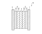
以下、本発明の第1実施例に係る燃料電池システム100の説明を行う。まず、燃料電池システム100に含まれる燃料電池スタック31を構成する燃料電池セル10について説明する。図1は、燃料電池セル10の模式的断面図である。図1に示すように、燃料電池セル10は、セパレータ1、燃料極2、電解質膜3、酸素極4およびセパレータ5が順に積層された構造を有する。燃料極2は、セパレータ1側からガス拡散層21および触媒層22が順に積層された構造を有する。酸素極4は、セパレータ5側からガス拡散層41および触媒層42が順に積層された構造を有する。
Hereinafter, the
セパレータ1,5は、ステンレス等の導電性材料から構成される。セパレータ1の燃料極2側の面には、燃料ガスが流動するための燃料ガス流路が形成されている。セパレータ5の酸素極4側の面には、酸化剤ガスが流動するための酸化剤ガス流路が形成されている。
The
ガス拡散層21は、燃料ガスを拡散させるための層であり、カーボンペーパ等の導電性材料から構成される。触媒層22は、水素のプロトン化を促進するためのPt(白金)、Pt合金等の触媒を含有する。また、触媒層22は、水の電気分解を促進するための水電解触媒を含有する。水電解触媒としては、Pt,Ru(ルテニウム),Ir(イリジウム),Au(金),Ni(ニッケル),Ag等の金属、Pt−Ru,Pt−Ir等の合金、RuO2,IrO2等の金属酸化物等を用いることができる。触媒層22は、例えば、Pt担持カーボン、Pt合金担持カーボン、白金ブラック等に上記水電解触媒が添加された構造を有する。なお、担持カーボンは、高結晶化カーボンであることが好ましい。触媒層22の耐酸化性が向上するからである。
The
電解質膜3は、プロトン伝導性を有するパーフルオロスルフォン酸型ポリマーであるnafion(登録商標)等の固体高分子電解質からなる。含水状態で、−30℃における電解質膜3の水透過速度は、5×10⁻⁴mmol/cm2/sec以上であることが好ましい。
The
ガス拡散層41は、酸化剤ガスを拡散させるための層であり、カーボンペーパ等の導電性材料から構成される。触媒層42は、触媒を担持する導電性材料等から構成される。触媒層42における触媒は、プロトンと酸素との反応を促進するための触媒である。本実施例においては、触媒層42は白金担持カーボンから構成される。
The
続いて、燃料電池セル10の動作の概要について説明する。まず、水素ガス、メタノールガス等の水素を含有する燃料ガスは、セパレータ1の燃料ガス流路を流動しつつガス拡散層21に供給される。ガス拡散層21に供給された燃料ガスは、ガス拡散層21を透過して触媒層22に到達する。触媒層22に到達した燃料ガス中の水素は、プロトンと電子とに解離する。この場合の反応式としては、下記の式(1)、(2)等が考えられる。プロトンは、電解質膜3を伝導し、酸素極4に到達する。
H2 → 2H+ + 2e− (1)
CH3OH + H2O → CO2 + 6H+ + 6e− (2)
Then, the outline | summary of operation | movement of the
H 2 → 2H + + 2e − (1)
CH 3 OH + H 2 O → CO 2 + 6H + + 6e − (2)
一方、酸素を含有する酸化剤ガスは、セパレータ5の酸化剤ガス流路を流動しつつガス拡散層41に供給される。ガス拡散層41に供給された酸化剤ガスは、ガス拡散層41を透過して触媒層42に到達する。触媒層42に到達した酸化剤ガス中の酸素とプロトンとから水が発生するとともに電力が発生する。発生した電力は、セパレータ1,5によって回収される。以上の動作によって、燃料電池セル10は発電を行う。
On the other hand, the oxidant gas containing oxygen is supplied to the
続いて、配流不良時、起動時等の燃料欠乏時における燃料電池セル10の作用について説明する。燃料が欠乏すると、燃料極2においてプロトンに解離する水素が欠乏することになる。したがって、燃料電池セル10において発電を継続するためには水素以外の材料からプロトンが解離することになる。この場合、主として燃料極2に保持された水が解離する。反応式としては、下記式(3)、(4)が考えられる。
2H2O → 4H+ + 4e− + O2 (3)
2H2O + C → 4H+ + 4e− + CO2 (4)
Next, the operation of the
2H 2 O → 4H + + 4e − + O 2 (3)
2H 2 O + C → 4H + + 4e − + CO 2 (4)
本実施例においては、触媒層22に水電解触媒が含有されていることから、水の電気分解が促進される。したがって、式(3)の反応が優先して行われる。それにより、燃料極2に含まれるカーボン等の不可逆な酸化劣化を抑制することができる。
In the present embodiment, since the water electrocatalyst is contained in the
続いて、本実施例に係る燃料電池システム100について説明する。図2は、本実施例に係る燃料電池システム100の全体構成を示す模式図である。図2に示すように、燃料電池システム100は、燃料電池20、燃料ガス供給手段30、酸化剤ガス供給手段40、背圧制御弁50および制御部60を備える。
Next, the
燃料電池20は、燃料電池スタック31、ヒータ32、電圧センサ33、温度センサ34および荷重センサ35を備える。燃料電池スタック31は、図1の燃料電池セル10が複数積層されて締結された構造を有する。ヒータ32は、燃料電池スタック31を覆っている。ヒータ32は、制御部60の指示に従って、燃料電池スタック31の温度を制御する。
The
電圧センサ33は、各燃料電池セル10の発電電圧を検出し、その検出結果を制御部60に与える。温度センサ34は、各燃料電池セル10の温度を検出し、その検出結果を制御部60に与える。荷重センサ35は、燃料電池スタック31における締結荷重を検出し、その検出結果を制御部60に与える。荷重センサ35は、それぞれの燃料電池セル10に1つずつ設けられていてもよく、燃料電池スタック31に1つ設けられていてもよい。
The
燃料ガス供給手段30および酸化剤ガス供給手段40は、ポンプ等から構成される。燃料ガス供給手段30は、燃料電池20の燃料ガス入口に接続されている。酸化剤ガス供給手段40は、燃料電池20の酸化剤ガス入口に接続されている。燃料ガス供給手段30は、制御部60の指示に従って、水素を含有する燃料ガスを燃料電池20の入口に供給する。燃料ガスとしては、水素ガス、メタノールガス等を用いることができる。酸化剤ガス供給手段40は、制御部60の指示に従って、酸化剤ガスを燃料電池20の酸化剤入口に供給する。酸化剤ガスとしては、エア等を用いることができる。
The fuel gas supply means 30 and the oxidant gas supply means 40 are constituted by a pump or the like. The fuel gas supply means 30 is connected to the fuel gas inlet of the
背圧制御弁50は、燃料電池20の酸化剤ガス出口に設けられている。背圧制御弁50は、制御部60の指示に従って、燃料電池20内を流動する酸化剤ガスの背圧を制御する。制御部60は、CPU(中央演算処理装置)、ROM(リードオンリメモリ)、RAM(ランダムアクセスメモリ)等から構成される。制御部60は、電圧センサ33、温度センサ34および荷重センサ35の検出結果に基づいて、燃料電池システム100の各部を制御する。
The back
続いて、制御部60による燃料電池システム100の制御について図3〜図7を参照しつつ説明する。まず、制御部60は、燃料電池20に燃料ガスおよび酸化剤ガスが供給されるように燃料ガス供給手段30および酸化剤ガス供給手段40を制御する。それにより、燃料電池20において発電が行われる。次に、制御部60は、燃料電池20において燃料が欠乏していないか否かを判定する。ここで、燃料が欠乏している燃料電池セル10においては、発電電圧がマイナスになる。図3を参照して詳細を説明する。
Next, control of the
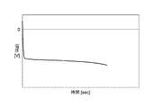
図3は、燃料が欠乏している燃料電池セル10の発電電圧を示す図である。図3の縦軸は燃料電池セル10の発電電圧を示し、図3の横軸は経過時間を示す。図3に示すように、燃料が欠乏すると急激に発電電圧が低下する。これは、燃料以外の材料からプロトンを解離させるためである。その後、発電電圧の低下幅は小さくなる。これは、水電解触媒を介して上記式(3)の反応が起こり、プロトンが継続して電解質膜3に供給されるからである。さらに燃料欠乏状態が継続すると、発電電圧は急激に低下する。これは、水電解触媒の劣化によって上記式(3)の反応の代わりに上記式(4)の反応が行われるからである。以上のことから、制御部60は、いずれかの燃料電池セル10の発電電圧が0V以下である場合に、その燃料電池セル10において燃料が欠乏していると判定することができる。
FIG. 3 is a diagram showing the power generation voltage of the
燃料が欠乏していると判定された場合、制御部60は、その燃料電池セル10の温度が氷点下になっているか否かを判定する。制御部60は、温度センサ34の検出結果に基づいて判定する。氷点下においては水が凍結するため、触媒層22への水の供給がなされない。この場合、電解質膜3に保持される水が触媒層22へ移動して、水電解触媒を介して電気分解される。したがって、電解質膜3の膜厚が小さくなる。その結果、燃料電池スタック31の締結荷重が低下する。
When it is determined that the fuel is deficient, the
ここで、燃料が欠乏しかつ温度が氷点下である場合の燃料電池セル10の発電電圧と燃料電池スタック31の締結荷重との関係について説明する。図4は、燃料電池セル10の発電電圧と燃料電池スタック31の締結荷重との関係を示す図である。この場合、燃料極2および酸素極4のいずれにも窒素ガスが供給され、燃料電池セル10の温度は−20℃に設定してあり、燃料電池セル10の電流密度は0.1A/cm2に設定してある。図4の左側の縦軸は燃料電池セル10の発電電圧を示し、図4の右側の縦軸は燃料電池スタック31の締結荷重を示し、図4の横軸は経過時間を示す。
Here, the relationship between the power generation voltage of the
図4に示すように、燃料欠乏状態が継続すると、燃料電池スタック31の締結荷重は徐々に低下する。したがって、荷重センサ35の検出荷重が低下すれば、燃料欠乏状態かつ氷点下の電解質膜3の水分量が低下していると判定することができる。そこで、制御部60は、荷重センサ35の検出荷重が低下するか否かを判定する。この場合、制御部60は、荷重センサ35の検出荷重が継続して低下するか否か判定してもよく、所定の時間間隔を空けて荷重センサ35の検出荷重が低下するか否かを判定してもよい。
As shown in FIG. 4, when the fuel-deficient state continues, the fastening load of the
荷重センサ35の検出荷重が低下すると判定された場合、制御部60は、背圧制御弁50を制御して、燃料電池20に供給される酸化剤ガスの背圧を増大させる。この場合、酸素極4において生成された発電生成水が電解質膜3および燃料極2側へ移動する。それにより、電解質膜3が十分に吸水することができるとともに、燃料極2における水の電気分解反応を継続させることができる。
When it is determined that the load detected by the
ここで、燃料が欠乏しかつ温度が氷点下である場合の酸化剤ガスの背圧と燃料電池セル10の発電電圧との関係について説明する。図5は、酸化剤ガスの背圧と燃料電池セル10の発電電圧との関係を示す図である。この場合、燃料極2には窒素ガスが供給され、酸素極4にはエアが供給され、燃料電池セル10の温度は−20℃に設定され、燃料電池セル10の電流密度は0.15A/cm2に設定されている。図5の縦軸は燃料電池セル10の発電電圧を示し、図5の横軸は経過時間を示す。実線は酸化剤ガスの背圧が0.2MPaの場合を示し、破線は酸化剤ガスの背圧が0.1MPaの場合を示す。
Here, the relationship between the back pressure of the oxidant gas and the power generation voltage of the
図5に示すように、背圧が0.1MPaの場合には、発電電圧が急激に低下する。これは、酸化剤ガスの背圧が小さいために酸素極4から燃料極2に水が供給されないからであると考えられる。一方、背圧が0.2MPaの場合には、発電電圧は一定の範囲内の値に長時間にわたって維持される。これは、酸素極4から燃料極2に水が供給されて水の電気分解反応が継続するからであると考えられる。
As shown in FIG. 5, when the back pressure is 0.1 MPa, the generated voltage rapidly decreases. This is considered to be because water is not supplied from the oxygen electrode 4 to the
なお、酸素極4から燃料極2に水が速やかに移動するためには、電解質膜3の水透過速度が所定の値よりも大きいことが必要である。ここで、燃料が欠乏しかつ温度が氷点下である場合における電解質膜3の水透過速度と燃料電池セル10の発電電圧との関係について説明する。
In order to move water from the oxygen electrode 4 to the
図6は、電解質膜3の水透過速度と燃料電池セル10の発電電圧との関係を示す図である。この場合、燃料極2には窒素ガスが供給され、酸素極4にはエアが供給され、燃料電池セル10の温度は−30℃に設定され、燃料電池セル10の電流密度は0.1A/cmに設定されている。図6の縦軸は燃料電池セル10の発電電圧を示し、図6の横軸は経過時間を示す。実線は電解質膜3の水透過速度が5×10−4mmol/cm2/secの場合を示し、破線は電解質膜3の水透過速度が1×10−4mmol/cm2/secの場合を示す。
FIG. 6 is a diagram showing the relationship between the water permeation rate of the
図6に示すように、水透過速度が1×10⁻⁴mmol/cm2/secの場合には発電電圧が急激に低下する。これは、水透過速度が小さいために酸素極4から燃料極2への水の供給が十分になされないからであると考えられる。一方、水透過速度が5×10−4mmol/cm2/secの場合には、発電電圧は一定の範囲内の値を長時間にわたって維持する。これは、酸素極4から燃料極2に水が十分に供給されて水の電気分解反応が継続するからであると考えられる。したがって、電解質膜3の水透過速度は、5×10−4mmol/cm2/sec以上であることが好ましい。
As shown in FIG. 6, when the water permeation rate is 1 × 10 −4 mmol / cm 2 / sec, the generated voltage rapidly decreases. This is presumably because the water permeation rate is low, so that water is not sufficiently supplied from the oxygen electrode 4 to the
制御部60は、酸化剤ガスの背圧を増加させた後に燃料電池スタック31の締結荷重が低下しているか否かを再度判定する。酸化剤ガスの背圧を増加させても燃料電池スタック31の締結荷重が低下する場合には、制御部60は、ヒータ32を制御して燃料電池スタック31を加熱する。この場合、電解質膜3における水透過速度が増大する。それにより、酸素極4側から燃料極2側に水が移動しやすくなる。その結果、燃料極2における水の電気分解反応が継続する。
The
ここで、燃料が欠乏しかつ温度が氷点下である場合における燃料電池セル10の温度と燃料電池セル10の発電電圧との関係について説明する。図7は、燃料電池セル10の温度と燃料電池セル10の発電電圧との関係を示す図である。この場合、燃料極2には窒素ガスが供給され、酸素極4にはエアが供給され、燃料電池セル10の電流密度は0.1A/cm2に設定されている。図7の縦軸は燃料電池セル10の発電電圧を示し、図7の横軸は経過時間を示す。実線は燃料電池セル10の温度が−20℃である場合を示し、破線は燃料電池セル10の温度が−26℃である場合を示し、点線は燃料電池セル10の温度が−30℃である場合を示す。
Here, the relationship between the temperature of the
図7に示すように、燃料電池セル10の温度が−30℃または−26℃である場合には、燃料電池セル10の発電電圧は急激に低下する。これは、電解質膜3の水透過速度が小さく、燃料極2に水が十分に供給されないからであると考えられる。一方、燃料電池セル10の温度が−20℃である場合には、燃料電池セル10の発電電圧は一定の範囲内の値に長時間にわたって維持される。これは、電解質膜3の水透過速度が増加し、燃料極2に水が十分に供給されるからであると考えられる。
As shown in FIG. 7, when the temperature of the
このように、燃料が欠乏しかつ温度が氷点下である場合であっても、電解質膜3の温度を増大させることによって酸素極4から燃料極2に水を十分に供給することができる。それにより、燃料極2の劣化を抑制することができるとともに、電解質膜3の劣化も抑制することができる。特に、nafion等のフッ素系電解質膜は、−26℃を境に水透過速度が急激に増加する。したがって、電解質膜3を−26℃以上に加熱することが好ましい。
Thus, even when the fuel is deficient and the temperature is below freezing, water can be sufficiently supplied from the oxygen electrode 4 to the
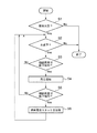
図8は、燃料電池20の発電中における制御部60による燃料電池システム100の制御の一例を示すフローチャートである。制御部60は、所定の周期で図8のフローチャートを実行する。図8に示すように、まず制御部60は、いずれかの燃料電池セル10が燃料欠乏状態にあるか否かを判定する(ステップS1)。この場合、制御部60は、電圧センサ33の検出結果に基づいて、いずれかの燃料電池セル10の発電電圧が0V以下であるか否かによって判定する。
FIG. 8 is a flowchart illustrating an example of control of the
ステップS1においていずれかの燃料電池セル10において燃料欠乏状態にあると判定された場合、制御部60は、その燃料電池セル10の温度が氷点下であるか否かを判定する(ステップS2)。この場合、制御部60は、温度センサ34の検出結果に基づいて判定する。ステップS2において燃料電池20の温度が氷点下であると判定された場合、制御部60は、燃料電池スタック31の締結荷重が低下傾向にあるか否かを判定する(ステップS3)。この場合、制御部60は、荷重センサ35の検出結果に基づいて、所定の時間間隔で締結荷重が低下しているか否かによって判定する。
When it is determined in step S1 that any one of the
ステップS3において燃料電池スタック31の締結荷重が低下傾向にあると判定された場合、制御部60は、背圧制御弁50を制御して酸化剤ガスの背圧を例えば0.2MPaまで増加させる(ステップS4)。次に、制御部60は、燃料電池スタック31の締結荷重が低下傾向にあるか否かを再度判定する(ステップS5)。ステップS5において燃料電池スタック31の締結荷重が低下傾向にあると判定された場合、制御部60は、ヒータ32を制御して燃料電池スタック31を加熱する(ステップS6)。この場合、制御部60は、燃料電池スタック31の温度が−26℃以上になるようにヒータ32による加熱を継続させる。その後、制御部60は、ステップS2の動作から繰り返す。
When it is determined in step S3 that the fastening load of the
なお、ステップS1においていずれかの燃料電池セル10が燃料欠乏状態にあると判定されなかった場合およびステップS2において燃料電池セル10の温度が氷点下であると判定されなかった場合、制御部60は、動作を終了する。それにより、燃料電池20は、発電を継続する。ステップS3およびステップS5において燃料電池スタック31の締結荷重が低下傾向にあると判定されなかった場合、制御部60は、ステップS2の動作から繰り返す。
If it is not determined in step S1 that any of the
このように、図8のフローチャートに従った制御によって、いずれかの燃料電池セル10において燃料が欠乏しかつ温度が氷点下である場合であっても、電解質膜3に保持された水以外の水を用いて電気分解反応を継続させることができる。それにより、燃料極2の劣化を抑制することができるとともに、電解質膜3の劣化も抑制することができる。
As described above, by the control according to the flowchart of FIG. 8, water other than the water retained in the
本実施例においては、背圧制御弁50が移動手段および背圧調整手段に相当し、荷重センサ35が含水量検出手段および荷重検出手段に相当し、制御部60が第1の判定手段、第2の判定手段および制御手段に相当し、電圧センサ33が発電電圧検出手段に相当し、温度センサ34が温度検出手段に相当する。
In this embodiment, the back
続いて、本発明の第2実施例に係る燃料電池システム100aについて説明する。図9は、燃料電池システム100aの全体構成を示す模式図である。図9に示すように、燃料電池システム100aが図2の燃料電池システム100と異なる点は、荷重センサ35の代わりに抵抗センサ36が設けられている点である。抵抗センサ36は、各燃料電池セル10の電解質膜3の電気抵抗を検出し、その検出結果を制御部60に与える。
Subsequently, a
ここで、燃料が欠乏しかつ温度が氷点下である場合の燃料電池セル10の発電電圧と電解質膜3の電気抵抗との関係について説明する。図10は、燃料電池セル10の発電電圧と電解質膜3の電気抵抗との関係を示す図である。この場合、燃料極2および酸素極4のいずれにも窒素ガスが供給され、燃料電池セル10の温度は−20℃に設定され、燃料電池セル10の電流密度は0.1A/cm2に設定されている。また、各電解質膜3の電気抵抗は、保持水量を変化させることによって変化させてある。なお、電解質膜3の電気抵抗は、保持水量が多ければ小さく、保持水量が少なければ大きい。
Here, the relationship between the power generation voltage of the
図10の縦軸は燃料電池セル10の発電電圧を示し、図10の横軸は経過時間を示す。図10に示すように、電解質膜3の電気抵抗が大きくなるにしたがって、発電電圧の低下幅が小さくなる時間が短くなる。したがって、電解質膜3の電気抵抗が大きければ電解質膜3の劣化が進行するとともに、燃料極2の劣化も進行する。以上のことから、電解質膜3の電気抵抗が大きい場合には、電解質膜3および燃料極2に水分を供給する必要がある。
The vertical axis in FIG. 10 indicates the power generation voltage of the
本実施例においては、制御部60は、燃料が欠乏しかつ温度が氷点下である場合に、電解質膜3の電気抵抗に基づいて電解質膜3の保持水が減少しているか否かを判定する。この場合、制御部60は、抵抗センサ36の検出抵抗が継続して増加するか否かに基づいて判定してもよく、所定の時間間隔を空けて抵抗センサ36の検出抵抗が低下するか否かに基づいて判定してもよい。
In the present embodiment, the
電解質膜3の保持水が減少していると判定された場合、制御部60は、背圧制御弁50を制御して、燃料電池20に供給される酸化剤ガスの背圧を増大させる。この場合、酸素極4において生成された発電生成水が電解質膜3および燃料極2側へ移動する。それにより、電解質膜3が十分に吸水することができるとともに、燃料極2における水の電気分解反応が継続して行われる。
When it is determined that the water retained in the
図11は、燃料電池20の発電中における制御部60による燃料電池システム100aの制御の一例を示すフローチャートである。制御部60は、所定の周期で図11のフローチャートを実行する。図11に示すように、まず制御部60は、いずれかの燃料電池セル10が燃料欠乏状態にあるか否かを判定する(ステップS11)。ステップS11においていずれかの燃料電池セル10が燃料欠乏状態にあると判定された場合、制御部60は、その燃料電池セル10の温度が氷点下であるか否かを判定する(ステップS12)。
FIG. 11 is a flowchart illustrating an example of control of the
ステップS12において燃料電池セル10の温度が氷点下であると判定された場合、制御部60は、その燃料電池セル10に含まれる電解質膜3の電気抵抗が増加傾向にあるか否かを判定する(ステップS13)。この場合、制御部60は、抵抗センサ36の検出結果に基づいて、所定の時間間隔で電解質膜3の電気抵抗が増加しているか否かによって判定する。
When it is determined in step S12 that the temperature of the
ステップS13において電解質膜3の電気抵抗が増加傾向にあると判定された場合、制御部60は、背圧制御弁50を制御して酸化剤ガスの背圧を増加させる(ステップS14)。次に、制御部60は、ステップS13において電気抵抗が低下傾向にあると判定された電解質膜3の電気抵抗が、増加傾向にあるか否かを再度判定する(ステップS15)。ステップS15においてその電解質膜3の電気抵抗が増加傾向にあると判定された場合、制御部60は、ヒータ32を制御して燃料電池スタック31を加熱する(ステップS16)。その後、制御部60は、ステップS12の動作から繰り返す。
When it is determined in step S13 that the electrical resistance of the
なお、ステップS11においていずれかの燃料電池セル10が燃料欠乏状態にあると判定されなかった場合およびステップS12において燃料電池セル10の温度が氷点下であると判定されなかった場合、制御部60は、動作を終了する。それにより、燃料電池20は発電を継続させる。ステップS13およびステップS15におい電解質膜3の電気抵抗が増加傾向にあると判定されなかった場合、制御部60は、ステップS12の動作から繰り返す。
If it is not determined in step S11 that any of the
このように、図11のフローチャートに従った制御によって、燃料が欠乏しかつ燃料電池セル10の温度が氷点下である場合であっても、電解質膜3に保持された水以外の水を用いて電気分解反応を継続させることができる。それにより、燃料極2の劣化を抑制することができるとともに、電解質膜3の劣化も抑制することができる。
Thus, by the control according to the flowchart of FIG. 11, even when the fuel is depleted and the temperature of the
なお、本実施例においては、抵抗センサ36が抵抗検出手段に相当する。 In the present embodiment, the resistance sensor 36 corresponds to resistance detection means.
2 燃料極
3 電解質膜
4 酸素極
10 燃料電池セル
20 燃料電池
22 アノード触媒層
30 燃料ガス供給手段
31 燃料電池スタック
32 ヒータ
33 電圧センサ
34 温度センサ
35 荷重センサ
36 抵抗センサ
40 酸化剤ガス供給手段
50 背圧調整手段
60 制御部
100,100a 燃料電池システム
2
Claims (14)
発電によって生成された前記燃料電池セルの酸素極の水を燃料極側に移動する移動手段と、
前記固体高分子電解質膜の含水量を検出する含水量検出手段と、
前記含水量検出手段の検出結果に基づいて前記移動手段を制御する制御手段と、
前記固体高分子電解質膜の含水量が低下するか否かを判定する第1の判定手段と、
前記燃料電池セルが燃料欠乏状態にあるか否かを判定する第2の判定手段と、
前記燃料電池セルの温度を検出する温度検出手段と、を備え、
前記制御手段は、前記燃料電池セルの温度が氷点下であり、前記燃料電池セルが燃料欠乏状態にあると前記第2の判定手段によって判定されかつ前記固体高分子電解質膜の含水量が低下すると前記第1の判定手段によって判定された場合に、前記酸素極の水を前記燃料極に移動するように前記移動手段を制御することを特徴とする燃料電池システム。 A fuel cell comprising a solid polymer electrolyte membrane and an anode catalyst layer comprising a water electrocatalyst;
Moving means for moving water at the oxygen electrode of the fuel cell generated by power generation to the fuel electrode side;
Water content detecting means for detecting the water content of the solid polymer electrolyte membrane;
Control means for controlling the moving means based on the detection result of the water content detecting means;
First determination means for determining whether or not the water content of the solid polymer electrolyte membrane decreases;
Second determination means for determining whether or not the fuel cell is in a fuel-deficient state ;
Temperature detecting means for detecting the temperature of the fuel cell , and
When the temperature of the fuel cell is below freezing point , the control means is determined by the second determination means that the fuel cell is in a fuel-deficient state, and the water content of the solid polymer electrolyte membrane decreases, A fuel cell system that controls the moving means to move water of the oxygen electrode to the fuel electrode when determined by the first determining means.
前記第1の判定手段は、前記固体高分子電解質膜の電気抵抗が増加する場合に前記固体高分子電解質膜の含水量が低下すると判定することを特徴とする請求項2〜5のいずれかに記載の燃料電池システム。 The water content detecting means includes a resistance detecting means for detecting an electric resistance of the solid polymer electrolyte membrane,
The said 1st determination means determines with the water content of the said solid polymer electrolyte membrane falling, when the electrical resistance of the said solid polymer electrolyte membrane increases, The any one of Claims 2-5 characterized by the above-mentioned. The fuel cell system described.
前記含水量検出手段は、前記燃料電池スタックの締結荷重を検出する荷重検出手段を含み、
前記第1の判定手段は、前記燃料電池スタックの締結荷重が低下する場合に前記固体高分子電解質膜の含水量が低下すると判定することを特徴とする請求項1〜6のいずれかに記載の燃料電池システム。 A fuel cell stack in which a plurality of the fuel cells are stacked;
The moisture content detection means includes a load detection means for detecting a fastening load of the fuel cell stack,
The said 1st determination means determines with the water content of the said solid polymer electrolyte membrane falling, when the fastening load of the said fuel cell stack falls, The Claim 1 characterized by the above-mentioned. Fuel cell system.
前記第2の判定手段は、前記燃料電池セルの発電電圧が所定値以下である場合に、前記燃料電池セルが燃料欠乏状態にあると判定することを特徴とする請求項1記載の燃料電池システム。 A power generation voltage detecting means for detecting the power generation voltage of the fuel cell,
2. The fuel cell system according to claim 1, wherein the second determination unit determines that the fuel cell is in a fuel-deficient state when a power generation voltage of the fuel cell is equal to or lower than a predetermined value. .
前記固体高分子電解質膜の含水量が低下するか否かを判定し、前記燃料電池セルが燃料欠乏状態にあるか否かを判定する判定ステップと、
前記判定ステップにおいて、前記燃料電池セルが燃料欠乏状態にあると判定されかつ前記固体高分子電解質膜の含水量が低下すると判定された場合に、発電によって生成された前記燃料電池セルの酸素極の水を燃料極側に移動する移動ステップとを含むことを特徴とする燃料電池セルの運転方法。 Moisture content detection step for detecting the water content of the solid polymer electrolyte membrane of a fuel cell comprising a solid polymer electrolyte membrane and an anode catalyst layer comprising a water electrocatalyst when the temperature of the fuel cell is below freezing point When,
Determining whether or not the water content of the solid polymer electrolyte membrane is reduced, and determining whether or not the fuel cell is in a fuel-deficient state;
In the determination step, when it is determined that the fuel cell is in a fuel-deficient state and the water content of the solid polymer electrolyte membrane is decreased, the oxygen electrode of the fuel cell generated by power generation is reduced. And a movement step of moving water to the fuel electrode side.
Priority Applications (3)
| Application Number | Priority Date | Filing Date | Title |
|---|---|---|---|
| JP2006092576A JP5040138B2 (en) | 2006-03-29 | 2006-03-29 | Fuel cell system and fuel cell operating method |
| US12/294,494 US8426075B2 (en) | 2006-03-29 | 2007-03-27 | Fuel cell system, and operation method for fuel cell |
| PCT/IB2007/000770 WO2007110747A2 (en) | 2006-03-29 | 2007-03-27 | Fuel cell system, and operation method for fuel cell |
Applications Claiming Priority (1)
| Application Number | Priority Date | Filing Date | Title |
|---|---|---|---|
| JP2006092576A JP5040138B2 (en) | 2006-03-29 | 2006-03-29 | Fuel cell system and fuel cell operating method |
Publications (3)
| Publication Number | Publication Date |
|---|---|
| JP2007265921A JP2007265921A (en) | 2007-10-11 |
| JP2007265921A5 JP2007265921A5 (en) | 2009-05-14 |
| JP5040138B2 true JP5040138B2 (en) | 2012-10-03 |
Family
ID=38421670
Family Applications (1)
| Application Number | Title | Priority Date | Filing Date |
|---|---|---|---|
| JP2006092576A Expired - Fee Related JP5040138B2 (en) | 2006-03-29 | 2006-03-29 | Fuel cell system and fuel cell operating method |
Country Status (3)
| Country | Link |
|---|---|
| US (1) | US8426075B2 (en) |
| JP (1) | JP5040138B2 (en) |
| WO (1) | WO2007110747A2 (en) |
Families Citing this family (5)
| Publication number | Priority date | Publication date | Assignee | Title |
|---|---|---|---|---|
| GB0914562D0 (en) * | 2009-08-20 | 2009-09-30 | Johnson Matthey Plc | Catalyst layer |
| KR101339256B1 (en) | 2012-07-13 | 2013-12-09 | 현대자동차 주식회사 | Device and method for detecting water distribution in fuel cell stack |
| JP6705504B2 (en) * | 2016-09-07 | 2020-06-03 | 日産自動車株式会社 | Fuel cell system and control method thereof |
| JP7088061B2 (en) * | 2019-02-08 | 2022-06-21 | トヨタ自動車株式会社 | Fuel cell system |
| JP7136016B2 (en) * | 2019-06-18 | 2022-09-13 | トヨタ自動車株式会社 | fuel cell system |
Family Cites Families (12)
| Publication number | Priority date | Publication date | Assignee | Title |
|---|---|---|---|---|
| US7029775B2 (en) * | 1997-12-22 | 2006-04-18 | Kabushikikaisha Equos Research | Fuel cell system |
| US6936370B1 (en) * | 1999-08-23 | 2005-08-30 | Ballard Power Systems Inc. | Solid polymer fuel cell with improved voltage reversal tolerance |
| ES2209949T3 (en) * | 1999-08-23 | 2004-07-01 | Ballard Power Systems Inc. | ANODIC FUEL BATTERY STRUCTURE FOR TENSION INVESTMENT TOLERANCE. |
| WO2002103829A1 (en) * | 2001-06-15 | 2002-12-27 | Kabushiki Kaisha Toshiba | Solid polymer type fuel cell, and solid polymer type fuel cell generation system |
| JP4267570B2 (en) * | 2002-05-14 | 2009-05-27 | 本田技研工業株式会社 | Method for starting and stopping operation of gas sensor with built-in heater |
| JP3621078B2 (en) | 2002-06-20 | 2005-02-16 | 田中貴金属工業株式会社 | Fuel electrode of solid polymer electrolyte fuel cell |
| US20040013935A1 (en) * | 2002-07-19 | 2004-01-22 | Siyu Ye | Anode catalyst compositions for a voltage reversal tolerant fuel cell |
| JP4745603B2 (en) * | 2002-07-29 | 2011-08-10 | 株式会社デンソー | Fuel cell system |
| JP4162469B2 (en) | 2002-10-30 | 2008-10-08 | 本田技研工業株式会社 | Electrode structure for polymer electrolyte fuel cell |
| JP2004158274A (en) | 2002-11-06 | 2004-06-03 | Toyota Motor Corp | Moisture state estimation apparatus of fuel cell and fuel cell system |
| US7232627B2 (en) * | 2002-11-08 | 2007-06-19 | Honda Motor Co., Ltd. | Electrode for solid polymer fuel cell |
| US20060199051A1 (en) * | 2005-03-07 | 2006-09-07 | Dingrong Bai | Combined heat and power system |
-
2006
- 2006-03-29 JP JP2006092576A patent/JP5040138B2/en not_active Expired - Fee Related
-
2007
- 2007-03-27 US US12/294,494 patent/US8426075B2/en active Active
- 2007-03-27 WO PCT/IB2007/000770 patent/WO2007110747A2/en active Application Filing
Also Published As
| Publication number | Publication date |
|---|---|
| JP2007265921A (en) | 2007-10-11 |
| WO2007110747A3 (en) | 2007-12-06 |
| US20100227242A1 (en) | 2010-09-09 |
| WO2007110747A2 (en) | 2007-10-04 |
| US8426075B2 (en) | 2013-04-23 |
Similar Documents
| Publication | Publication Date | Title |
|---|---|---|
| JP6523273B2 (en) | Hydrogen system and method of operation | |
| JP2007128745A (en) | Electrochemical energy generation device and its operation method, as well as electrochemical device | |
| WO2006028021A1 (en) | Fuel cell power generating equipment driving method and fuel cell power generating equipment | |
| WO2005112173A1 (en) | System for producing electrochemical energy and method for driving such system | |
| JP5040138B2 (en) | Fuel cell system and fuel cell operating method | |
| JP2007265929A (en) | Fuel electrode for fuel cell, and fuel cell and fuel cell system equipped with it | |
| JP5439584B2 (en) | Fuel cell system and control method thereof | |
| JP5128072B2 (en) | Fuel cell power generation system | |
| US20080171244A1 (en) | Standalone Hydrogen Generating System | |
| US20080063910A1 (en) | Fuel Cell Power Generating Device | |
| JP2005276628A (en) | Electric power generation system using solid polymer electrolyte fuel cell, and stationary distributed electric power source system for domestic use | |
| JP2008027647A (en) | Fuel electrode for fuel cell, and fuel cell equipped with it | |
| JP2001338667A (en) | Fuel cell control system | |
| JP2016024924A (en) | Method of starting fuel battery system | |
| JP7088061B2 (en) | Fuel cell system | |
| JP2008027606A (en) | Fuel cell system | |
| JP5348600B2 (en) | Direct fuel cell system and control method thereof | |
| JP2012009182A (en) | Fuel cell system, power generation method of fuel cell and method of determining flooding | |
| JP2007323816A (en) | Fuel cell power generation device | |
| JP2009123469A (en) | Fuel battery power generation system | |
| JP5154043B2 (en) | Fuel cell system | |
| JP2016129155A (en) | Fuel cell system start method and fuel cell system | |
| JP2007305388A (en) | Fuel electrode for fuel cell, and fuel cell equipped with it | |
| JP2010055954A (en) | Electrode, fuel cell using the same, and electronic device | |
| KR100785820B1 (en) | Fuel supplying equipment for direct methanol fuel cell |
Legal Events
| Date | Code | Title | Description |
|---|---|---|---|
| A521 | Request for written amendment filed |
Free format text: JAPANESE INTERMEDIATE CODE: A523 Effective date: 20090326 |
|
| A621 | Written request for application examination |
Free format text: JAPANESE INTERMEDIATE CODE: A621 Effective date: 20090326 |
|
| A977 | Report on retrieval |
Free format text: JAPANESE INTERMEDIATE CODE: A971007 Effective date: 20120209 |
|
| A131 | Notification of reasons for refusal |
Free format text: JAPANESE INTERMEDIATE CODE: A131 Effective date: 20120313 |
|
| A521 | Request for written amendment filed |
Free format text: JAPANESE INTERMEDIATE CODE: A523 Effective date: 20120508 |
|
| TRDD | Decision of grant or rejection written | ||
| A01 | Written decision to grant a patent or to grant a registration (utility model) |
Free format text: JAPANESE INTERMEDIATE CODE: A01 Effective date: 20120612 |
|
| A01 | Written decision to grant a patent or to grant a registration (utility model) |
Free format text: JAPANESE INTERMEDIATE CODE: A01 |
|
| A61 | First payment of annual fees (during grant procedure) |
Free format text: JAPANESE INTERMEDIATE CODE: A61 Effective date: 20120625 |
|
| R151 | Written notification of patent or utility model registration |
Ref document number: 5040138 Country of ref document: JP Free format text: JAPANESE INTERMEDIATE CODE: R151 |
|
| FPAY | Renewal fee payment (event date is renewal date of database) |
Free format text: PAYMENT UNTIL: 20150720 Year of fee payment: 3 |
|
| LAPS | Cancellation because of no payment of annual fees |