JP5039732B2 - Packet transfer apparatus and packet transfer method - Google Patents
Packet transfer apparatus and packet transfer method Download PDFInfo
- Publication number
- JP5039732B2 JP5039732B2 JP2009055001A JP2009055001A JP5039732B2 JP 5039732 B2 JP5039732 B2 JP 5039732B2 JP 2009055001 A JP2009055001 A JP 2009055001A JP 2009055001 A JP2009055001 A JP 2009055001A JP 5039732 B2 JP5039732 B2 JP 5039732B2
- Authority
- JP
- Japan
- Prior art keywords
- frame
- data
- buffer
- sequence number
- received
- Prior art date
- Legal status (The legal status is an assumption and is not a legal conclusion. Google has not performed a legal analysis and makes no representation as to the accuracy of the status listed.)
- Expired - Fee Related
Links
Images


Abstract
Description
本願明細書で開示される技術は、パケット転送装置に関し、更に詳しくは、プロテクション機能を備え、複数のリンクを介して接続されるパケット転送装置及びシステムに関する。 The technology disclosed in the present specification relates to a packet transfer apparatus, and more particularly, to a packet transfer apparatus and system having a protection function and connected via a plurality of links.
政府は、「e−Japan戦略」及び「e−Japan重点計画」において、高度情報通信ネットワーク社会形成に向けた目標と、これを実現するために重点的に実施する必要がある具体的施策を提示した。その大きなテーマの一つが放送と通信の融合である。現在まで豊富なコンテンツを蓄積してきた放送と、急速に利便性を高めているコンピュータネットワークを融合させた、新たなネットワークサービスに対する期待が高まっている。 In the “e-Japan Strategy” and “e-Japan Priority Plan”, the government presents the goals for the formation of an advanced information and communication network society and specific measures that need to be implemented intensively in order to realize this goal. did. One of the major themes is the fusion of broadcasting and communication. Expectations are growing for new network services that fuse broadcasts that have accumulated abundant content to date with computer networks that are rapidly improving convenience.
放送サービスを現在のネットワーク上で実現するための、最も有力な技術はストリーミング技術である。ストリーミングサービスでは、指定された時間にフレームを再生する必要があるため、数秒先の再生データまで予めアプリケーションバッファに保持しておく仕組みになっている。このバッファに、連続的な再生をするのに十分なデータがないと判断される場合、一定量のデータを蓄えるまで再生が再開されない。このため、放送サービスでは、通信の遅延や揺らぎに加え、フレーム損失が品質に大きな影響を与えるため、ネットワーク上でのフレーム損失を防止することが最も重要である。 Streaming technology is the most promising technology for realizing broadcasting services on current networks. In the streaming service, since it is necessary to reproduce a frame at a specified time, the reproduction buffer that is several seconds ahead is stored in the application buffer in advance. If it is determined that there is not enough data in this buffer for continuous playback, playback will not resume until a certain amount of data is stored. For this reason, in broadcast services, in addition to communication delays and fluctuations, frame loss greatly affects quality, so it is most important to prevent frame loss on the network.
現在のIP(Internet Protocol)ネットワークでは、上位層プロトコルであるTCP(Transport Control Protocol)の再送制御によってフレーム損失を防止している。しかし、再送制御では遅延の増大が懸念される。このため、放送サービスのような大きな遅延を許容しないサービスには適用できない。従って、放送サービスデータを転送する際の上位層プロトコルはUDP(User Datagram Protocol)が使用される。しかし、UDPはフレーム損失を防止するための機能を有していない。そこで、通信経路を二重化し、フレーム損失を防止するプロテクションが必要となる。特に、送信側装置から複数経路にフレームのコピーを送信し、受信側装置でそれらを選択し、転送する1+1プロテクションは、フレーム損失を防止するのに最も有効である。 In the current IP (Internet Protocol) network, frame loss is prevented by retransmission control of TCP (Transport Control Protocol) which is an upper layer protocol. However, there is a concern about an increase in delay in retransmission control. For this reason, it cannot be applied to a service that does not allow a large delay such as a broadcast service. Accordingly, UDP (User Datagram Protocol) is used as an upper layer protocol for transferring broadcast service data. However, UDP does not have a function for preventing frame loss. Therefore, it is necessary to provide protection for duplexing communication paths and preventing frame loss. In particular, 1 + 1 protection, in which copies of frames are transmitted from a transmission side device to a plurality of paths, selected by the reception side device, and transferred, is most effective in preventing frame loss.
1+1プロテクションでは、送信側装置はフレームにシーケンス番号を付与し、そのフレームをコピーして複数の通信経路に送信する。あるフレームと、そのフレームのコピーには、同一のシーケンス番号が付与される。一方、受信側装置は複数経路からのフレームのシーケンス番号を監視し、正常なフレームを選択して転送する。 In 1 + 1 protection, the transmission side device assigns a sequence number to a frame, copies the frame, and transmits the frame to a plurality of communication paths. The same sequence number is assigned to a certain frame and a copy of the frame. On the other hand, the receiving side apparatus monitors the sequence numbers of frames from a plurality of paths, selects a normal frame, and transfers it.
特許文献1では、送信側装置がVoIP(Voice over IP)トラヒックを複数の経路に送信する。受信側装置は、フレームに付与されているシーケンス番号とアドレスを対応させたフレームバッファに、複数経路からのフレームを格納する。そして、そのフレームバッファから順番にフレームを読み出すことで、シーケンス番号順にフレームを転送することを実現している。これによって、バッファ内のフレーム入れ替えなどの複雑な処理なしに、フレームの損失及び順序逆転を防止できる。
特許文献1を含む従来の1+1プロテクションは、VoIPやTDM(Time Division Multiplex)エミュレーションのような、フレーム送信周期が一定で、かつ固定長フレームの処理を行うサービスが前提であった。このため、複数の論理フローが多重された場合でも、各論理フローにタイムスロットを割当て、受信側装置のフレームバッファからは一定の周期で読み出すことが可能であった。
The conventional 1 + 1 protection including
しかし、放送サービスは上述のように、数秒先の再生データまで予めアプリケーションバッファに保持しておく仕組みになっているため、そのトラヒックはバースト性を帯びており、フレームの到着は一定周期でない。さらに、フレーム長が可変長である。このため、複数フローが多重された場合に各フローにタイムスロットを割当てる方法を用いることができない。これは、可変長フレームにタイムスロットを割当てるには、その最大フレーム長にタイミングを合わせる必要があるため、通信回線の帯域を十分に活用できないことに加え、多重できる論理フロー数が通信回線の帯域によって制限されてしまうためである。また、仮に帯域の上限まで論理フローを多重した場合に、最大フレーム長に合わせたタイミング割り当てでは、バースト的に到着したフレームの転送が間に合わず、バッファオーバフローを発生させる可能性がある。 However, as described above, since the broadcast service has a structure in which the reproduction data of several seconds ahead is held in the application buffer in advance, the traffic is bursty, and the arrival of the frames is not a constant cycle. Furthermore, the frame length is variable. For this reason, when a plurality of flows are multiplexed, a method of assigning a time slot to each flow cannot be used. This is because in order to assign a time slot to a variable-length frame, it is necessary to match the timing to the maximum frame length, so that the bandwidth of the communication line cannot be fully utilized, and the number of logical flows that can be multiplexed is the bandwidth of the communication line. It is because it is limited by. Also, if the logical flows are multiplexed up to the upper limit of the bandwidth, the timing allocation according to the maximum frame length may not be able to transfer the frames arriving in bursts in time, and may cause a buffer overflow.
このため、バッファからのフレーム読み出しは不定期に実行する必要がある。つまり、バッファにフレームがあれば読み出すといった処理が必要になる。しかし、シーケンス番号順にフレームを転送する必要があるため、一つの通信経路(例えば、通信経路0系)で一つのフレームが損失した場合、その次のフレームが正常に受信され、バッファに格納されたとしても、損失したフレームと同一のシーケンス番号が付与されたフレームがもう一方の経路(例えば、通信経路1系)から到着するのを待つ必要がある。
For this reason, it is necessary to read frames from the buffer irregularly. In other words, it is necessary to read the frame if there is a frame in the buffer. However, because it is necessary to transfer the frames in the order of the sequence numbers, if one frame is lost on one communication path (for example,
具体的には、例えば、通信経路0系からのシーケンス番号(SN):2のフレームが損失し、受信側の転送装置が次のSN:3のフレームを受信した場合である。この場合、両系の転送遅延差の影響で、通信経路0系からのSN:3のフレームを受信した時点で、受信側の転送装置は通信経路1系からのSN:2のフレームを受信していない。このため、通信経路1系からのSM:2のフレームを受信するまで、受信側の転送装置はSN:3のフレームの転送を待つ必要がある。しかし、通信経路1系でも、SN:2のフレームが損失してしまった場合、受信側の転送装置は、そのフレームをいずれの系からも受信できないため、既にバッファに格納されているSN:3のフレームを転送することができなくなってしまう。
Specifically, for example, this is a case where a frame with a sequence number (SN): 2 from the
そこで、各通信経路においてフレームの順序逆転は発生しないと仮定して、両系からSN:3のフレームを受信した時点で、SN:2のフレームは両系で損失したと判断し、SN:3のフレームを送信してもよい。実際、1+1プロテクションを行うような高信頼ネットワークでは、同一フロー内での順序逆転は発生しないようにネットワークを構築することは容易であり、そうすることが普通である。しかし、上記の制御では、例えば通信経路1系で回線障害が発生した結果、通信経路1系からSN:3以降のフレームを受信することができなくなった場合、転送装置は、正常な通信経路0系からフレームを受信しても、それらを全く転送できなくなってしまうという課題があった。これでは、1+1プロテクションを実施している意味がなくなってしまう。
Therefore, assuming that the frame order is not reversed in each communication path, when the SN: 3 frame is received from both systems, it is determined that the SN: 2 frame is lost in both systems, and SN: 3 Frames may be transmitted. In fact, in a highly reliable network that performs 1 + 1 protection, it is easy to construct a network so that order reversal does not occur within the same flow, and it is common to do so. However, in the above control, for example, when a line failure occurs in the
本願で開示する代表的な発明は、対向装置から第1通信経路を介してシーケンス番号が付与されたデータを受信する第1のインタフェースと、前記対向装置から第2通信経路を介して前記シーケンス番号が付与されたデータを受信する第2のインタフェースと、前記受信したデータを格納するバッファと、前記各通信経路から前記データを受信すると、前記受信したデータと、前回受信したデータとの間の時間間隔を計測し、複数の前記計測された時間間隔の平均値を算出し、前記第1のインタフェースにおいて、第1シーケンス番号が付与された第1データを受信する前に前記第1シーケンス番号の次のシーケンス番号である第2シーケンス番号が付与された第2データを受信した場合、受信した前記第2データを前記バッファに格納し、前記算出された時間間隔の平均値に、前記第1通信経路におけるデータ転送遅延時間と前記第2通信経路におけるデータ転送遅延時間との差を加算することによって算出された待ち時間が経過したか否かを判定し、前記待ち時間が経過したと判定された場合、前記第2データを前記バッファから読み出し、前記待ち時間が経過したと判定される前に、前記第2のインタフェースにおいて、前記第1シーケンス番号が付与された前記第1データを受信する前に前記第2シーケンス番号が付与された前記第2データを受信した場合、前記第2データを前記バッファから読み出すバッファ制御部と、前記バッファから読み出された前記第2データを送出する第3のインタフェースと、を備えることを特徴とする。 A representative invention disclosed in the present application includes a first interface that receives data assigned a sequence number from a counter device via a first communication path, and the sequence number from the counter device via a second communication path. When receiving the data from each communication path, a time between the received data and the previously received data is received. An interval is measured, an average value of a plurality of the measured time intervals is calculated , and the first sequence number is received after receiving the first data to which the first sequence number is assigned in the first interface. If the second sequence number is the sequence number receives a second data attached, and storing the second data received in the buffer, Whether the waiting time calculated by adding the difference between the data transfer delay time in the first communication path and the data transfer delay time in the second communication path to the average value of the calculated time intervals has elapsed If it is determined that the waiting time has elapsed, the second data is read from the buffer, and before it is determined that the waiting time has elapsed , the first interface A buffer control unit that reads the second data from the buffer when receiving the second data to which the second sequence number is assigned before receiving the first data to which the sequence number is assigned; And a third interface for sending the read second data.
本発明の一実施形態によれば、放送サービスのような可変長フレームが非定期に到着するサービスに対して、1+1プロテクションを実施することによってフレーム損失を防止することが可能となるため、ユーザに対して高品質なサービスを提供することができる。 According to an embodiment of the present invention, it is possible to prevent frame loss by performing 1 + 1 protection for a service such as a broadcast service in which variable-length frames arrive irregularly. In contrast, high-quality services can be provided.
以下、本発明の実施形態について、図面を参照して説明する。 Hereinafter, embodiments of the present invention will be described with reference to the drawings.
図1は、本発明の第1の実施形態のパケット転送装置が適用される通信ネットワークの一例を示す説明図である。 FIG. 1 is an explanatory diagram illustrating an example of a communication network to which the packet transfer apparatus according to the first embodiment of this invention is applied.
パケット転送装置10Aは、2つ以上の通信経路(図1の例では、通信経路0系NW0及び通信経路1系NW1)を介して、対向のパケット転送装置10Nと接続される。この通信経路0系NW0及び通信経路1系NW1は物理回線であってもよいし、一つ以上のパケット転送装置によって構成されるネットワークであってもよい。さらに、パケット転送装置10Aは、端末70−1と接続される。
The
パケット転送装置10Aは、パケット転送装置10N及び端末70−1の間で、フレームの転送処理、すなわち、フレームを受信し、受信したフレームを必要に応じて加工し、そのフレームを送信する処理を実行する。具体的には、端末70−1がフレーム30をパケット転送装置10Aに出力すると、パケット転送装置10Aはフレーム送信順序情報を表すシーケンス番号32をフレーム30に付与し、そのフレーム30をコピーする。そして、パケット転送装置10Aは、フレーム30及びそのコピーを通信経路0系NW0及び通信経路1系NW1に送信する。
The
通信経路0系NW0及び通信経路1系NW1に接続される、パケット転送装置10A及び10Nの各インタフェースには、固有のアドレスが設定されている。パケット転送装置は、フレーム30を各通信経路に送信する際に、フレーム30が各通信経路に対応する受信側のパケット転送装置のインタフェースに到着するように、宛先アドレスを含むヘッダ33をフレーム30に付与する。
A unique address is set for each interface of the
対向のパケット転送装置10Nは、複数の通信経路から受信するフレームのシーケンス番号32を監視し、シーケンス番号に欠落及び逆転が発生しないように、シーケンス番号の順にフレーム34を端末70−nに転送する。フレーム34は、パケット転送装置10Nが、受信したフレームから不要なシーケンス番号32及びヘッダ33を削除することによって生成したものである。
The opposite
ここでは、端末70−1から端末70−nへの処理の流れを説明したが、逆方向の処理も全く同様に実行される。つまり、パケット転送装置10Aと10Nは全く同様の構成となる。
Here, the flow of processing from the terminal 70-1 to the terminal 70-n has been described, but processing in the reverse direction is executed in exactly the same manner. That is, the
パケット転送装置10A及びパケット転送装置10Nは、例えば、IP(Internet Protocol)パケットをペイロードとして含むイーサネット(登録商標)フレームを転送してもよい。しかし、本発明は、任意の形式のデータを転送するデータ転送装置に適用することができる。
The
図2は、本発明の第1の実施形態のパケット転送装置10Nの動作の概要を示す説明図である。
FIG. 2 is an explanatory diagram showing an outline of the operation of the
具体的には、図2は、通信経路0系NW0及び通信経路1系NW1からパケット転送装置10Nがフレームを受信するタイミングの一例、及び、それらのフレームを受信したパケット転送装置10Nが実行する処理の一例を示す。図2には、それぞれが二つの通信経路に対応する二つの横軸が表示される。これらの横軸は、各通信経路を経由するフレームをパケット転送装置10Nが受信するタイミングを示し、右に表示されるフレームほど早く受信されることを意味する。
Specifically, FIG. 2 illustrates an example of timing at which the
パケット転送装置10Nは、二つの通信経路、すなわち通信経路0系NW0及び通信経路1系NW1からフレームを受信している。受信するフレームには、フレームの送信順序を示すシーケンス番号(SN)が付与されている。同じシーケンス番号が付与された複数のフレームは、少なくとも、同一のペイロード405(図3参照)を含む。以下の説明において、複数のフレームの内容が同一であることは、それらのフレームが少なくとも同一のペイロード405を含むことを意味する。パケット転送装置10Nは、受信したフレームを一度バッファ(図5参照)に格納し、バッファにフレームがあれば即時読み出して端末70−nに転送する。この際、パケット転送装置10Nはシーケンス番号を監視しており、シーケンス番号に欠落及び逆転がないように、シーケンス番号の順にフレームを転送する。
The
図2の例では、シーケンス番号(SN):1のフレームからSN:4のフレームまでが、送信側のパケット転送装置10Aから順次送信されている。
In the example of FIG. 2, frames from sequence number (SN): 1 to SN: 4 are sequentially transmitted from the
図2には、通信経路0系NW0の転送遅延が通信経路1系NW1の転送遅延より小さい例を示す。このため、通信経路0系NW0を経由するフレームは、それと同一内容の、通信経路1系NW1を経由するフレームよりも常に先にパケット転送装置10Nに到着する。パケット転送装置10Nは、通常、通信経路0系NW0からのフレームを受信すると、そのフレームを、バッファに格納後、すぐに送信する。
FIG. 2 shows an example in which the transfer delay of the
図2の例では、パケット転送装置10Nは、最初に通信経路0系NW0からSN:1のフレーム301を受信する。この場合、パケット転送装置10Nは、受信したフレーム301をバッファに格納し、端末70−nに送信する。このときパケット転送装置10Nは、図1において説明したように、端末70−nに送信するフレームからシーケンス番号32及びヘッダ33を削除する。
In the example of FIG. 2, the
次に、パケット転送装置10Nは、通信経路1系NW1からSN:1のフレーム311を受信する。既にフレーム301が送信されていれば、パケット転送装置10Nは、さらにフレーム311を送信することはない。
Next, the
パケット転送装置10Nは、フレーム損失が発生していなければ、SN:1のフレーム301を受信した後、SN:2のフレーム302を受信するはずである。しかし、図2の例では、フレーム302が損失している。この場合、パケット転送装置10Nは、通信経路1系NW1からSN:2のフレーム312を受信し、そのフレーム312をバッファに格納し、端末70−nに送信する。
If no frame loss occurs, the
しかし、パケット転送装置10Nは、両系の転送遅延差のため、フレーム312を受信する前に通信経路0系NW0からSN:3のフレーム303を受信する場合がある。この場合、パケット転送装置10NはSN:3のフレーム303を既に受信しているにもかかわらず、通信経路1系NW1から到着する可能性のあるSN:2のフレーム312を待つ必要がある。言い換えると、パケット転送装置10Nは、受信したフレーム303をバッファに格納するが、フレーム312の受信及び送信が終了するまでフレーム303を送信することができない。このため、仮にフレーム312も損失した場合、パケット転送装置10Nは、フレーム303を正常に受信できたにもかかわらず、それを送信することができなくなる。
However, the
そこで、各通信経路において、フレームの順序は逆転しないと仮定することが考えられる。この場合、パケット転送装置10Nは、SN:2のフレーム302及びフレーム312を受信する前に、両通信経路からSN:3のフレーム303及びフレーム313を受信した時点で、SN:2のフレーム302及びフレーム312が両通信経路で損失したと判定し、SN:3のフレーム303又はフレーム313を送信することができる。
Therefore, it can be assumed that the frame order is not reversed in each communication path. In this case, the
しかし、上記の制御によれば、例えば通信経路に発生した障害のため、通信経路1系NW1のSN:3のフレーム313以降のフレームがさらに損失してしまった場合、パケット転送装置10Nは、通信経路0系NW0から正常に受信したSN:3のフレーム303を送信できず、さらに、それ以降のフレーム送信が全くできなくなってしまう。
However, according to the above control, for example, when a frame after the
このため、本実施形態のパケット転送装置10Nは、上記のようなフレームの損失によるシーケンス番号の欠落を検出した場合、フレームの送信を一時停止する。その際、パケット転送装置10Nは、両系の転送遅延差81をタイマ(図8参照)に設定し、カウントダウンを開始する。すなわち、タイマに設定された値は、カウントダウンが開始された後、時間の経過とともに減少し、最終的に‘0’になる。そして、このタイマが’0’になった時点、又は、パケット転送装置10NがSN:2のフレームを受信した時点、又は、パケット転送装置10Nが両系からSN:3のフレームを受信した時点で、パケット転送装置10Nは、フレームの送信を再開する。
For this reason, the
これによって、仮に図2のように1系NW1のSN:3のフレーム313が損失した場合、及び、片側の通信経路に回線障害が発生した場合にも、フレームの送信が完全に停止することなく、フレームの損失を防止することが可能となる。
As a result, even if the SN: 3
なお、上記及びこれから先の説明において、フレームが損失した場合(すなわち、パケット転送装置10Nがフレームを受信できなかった場合)には、パケット転送装置10Nにフレームが到着したが、そのフレームのFCS406又はFCS417(図3及び図4参照)を検査した結果、エラーが検出された場合も含まれる。その場合、フレームが廃棄されるため、パケット転送装置10Nは、到着したフレームを転送することができない。
In the above and the following description, when a frame is lost (that is, when the
図3は、本発明の第1の実施形態の端末70とパケット転送装置10A及び10Nとの間の通信に使用されるフレーム40のフォーマットを示す説明図である。
FIG. 3 is an explanatory diagram illustrating a format of the frame 40 used for communication between the terminal 70 and the
すなわち、フレーム40は、図1のフレーム30及びフレーム34に相当する。
That is, the frame 40 corresponds to the
フレーム40は、宛先MACアドレス401、送信元MACアドレス402、VLANタグ403、タイプ値404、ペイロード405及びフレームチェックシーケンス(FCS)406とからなる。
The frame 40 includes a
宛先MACアドレス401には、フレーム40の宛先であるパケット転送装置10A、パケット転送装置10N又は端末70のインタフェース(例えば図5の入出力回線インタフェース11)のMACアドレスが設定される。
In the
送信元MACアドレス402には、フレーム40を送信したパケット転送装置10A、パケット転送装置10N又は端末70のインタフェースのMACアドレスが設定される。
In the
VLANタグ403は、フロー識別子となるVLAN IDの値(VID♯)を示している。
A
タイプ値404は、後続ヘッダの種類を示す。
The
宛先MACアドレス401からタイプ値404までが、MACヘッダである。
The MAC header is from the
ペイロード405は、フレーム40によって伝送されるデータ(すなわちペイロード)である。ペイロード405には、上位プロトコルのパケット(例えばIPパケット)が格納されてもよい。
The
FCS406は、フレームのエラーを検出するための検査符号である。受信側のパケット転送装置10N等は、到着したフレームのFCS406を検査する。その結果、エラーが検出された場合、パケット転送装置10N等は、到着したフレームを破棄する。すなわち、そのフレームは損失したと判定される。
The
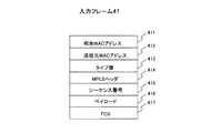
図4は、本発明の第1の実施形態の通信経路0系NW0及び通信経路1系NW1における通信に使用されるフレーム41のフォーマットを示す説明図である。
FIG. 4 is an explanatory diagram illustrating a format of the frame 41 used for communication in the
すなわち、フレーム41は、図1の例においてパケット転送装置10Aからパケット転送装置10Nに転送されるフレームに相当する。
That is, the frame 41 corresponds to a frame transferred from the
フレーム41は、宛先MACアドレス411、送信元MACアドレス412、タイプ値413、MPLSヘッダ414、シーケンス番号415、ペイロード416及びフレームチェックシーケンス(FCS)417からなる。
The frame 41 includes a
宛先MACアドレス411には、フレーム41の宛先であるパケット転送装置(図1の例では、パケット転送装置10A)のインタフェースのMACアドレスが設定される。
In the
送信元MACアドレス412には、フレーム41の送信元であるパケット転送装置(図1の例では、パケット転送装置10N)のインタフェースのMACアドレスが設定される。
In the
タイプ値413は、後続ヘッダの種類を示す。
The
宛先MACアドレス411からタイプ値413までが、MACヘッダである。
The MAC header is from the
MPLSヘッダ414は、フロー識別子となるラベルの値(ラベル#)を示している。
The
シーケンス番号415には、フロー毎のフレーム送信順序を示す連続的な整数が設定される。小さいシーケンス番号415が付与されたものほど早く送信されたフレームであることを示す。
In
ペイロード416には、端末70から送信されたフレーム40がそのまま格納される。
In the
FCS417は、フレームのエラーを検出するための検査符号である。FCS417は、FCS417と同様、受信側のパケット転送装置10N等によって検査される。
図5は、本発明の第1の実施形態のパケット転送装置10Nの構成を示すブロック図である。
FIG. 5 is a block diagram illustrating a configuration of the
なお、パケット転送装置10Aの構成は、パケット転送装置10Nの構成と同様であるため、説明を省略する。
Note that the configuration of the
パケット転送装置10Nは、複数のネットワークインタフェースボード(NIF)10−1〜10−n、及び、これらのNIFに接続されたフレーム中継部15からなる。以下、複数のNIF10−1〜10−nに共通する説明をする場合、これらを総称してNIF10と記載する。
The
各NIF10は、通信ポートとなる複数の入出力回線インタフェース11−1〜11−2を備え、これらの通信ポートを介して、端末70通信経路0系NW0又は通信経路1系NW1と接続されている。以下、複数の入出力回線インタフェース11−1〜11−2に共通する説明をする場合、これらを総称して入出力回線インタフェース11と記載する。図5には二つの入出力回線インタフェース11を示すが、各NIF10は、さらに多くの入出力回線インタフェース11を備えてもよい。本実施形態における入出力回線インタフェース11は、イーサネット(登録商標)用の回線インタフェースである。
Each
各NIF10は、入出力回線インタフェース11に接続された入力ヘッダ処理部12、及び、入力ヘッダ処理部12に接続された入力フレームバッファ制御部13を備える。さらに、各NIF10は、フレーム中継部15に接続された複数のスイッチ(SW)インタフェース14−1〜14−2、これらのSWインタフェース14−1〜14−2に接続された出力ヘッダ処理部16、及び、出力ヘッダ処理部16に接続された出力フレームバッファ制御部17を備える。以下、複数のSWインタフェース14−1〜14−2に共通する説明をする場合、これらを総称してSWインタフェース14と記載する。図5には二つのSWインタフェース14を示すが、各NIF10は、さらに多くのSWインタフェース14を備えてもよい。
Each
ここで、SWインタフェース14−iは、入出力回線インタフェース11−iと対応しており、入出力回線インタフェース11−iが受信した入力フレームは、SWインタフェース14−iを介してフレーム中継部15に転送される。また、フレーム中継部15からSWインタフェース14−iに振り分けられた出力フレームは、入出力回線インタフェース11−iを介して、出力回線に送信される。
Here, the SW interface 14-i corresponds to the input / output line interface 11-i, and the input frame received by the input / output line interface 11-i is sent to the
なお、図5の例では、iは1又は2のいずれかである。例えば、入出力回線インタフェース11−1が受信した入力フレームは、SWインタフェース14−1を介してフレーム中継部15に転送される。フレーム中継部15からSWインタフェース14−1に振り分けられた出力フレームは、入出力回線インタフェース11−1を介して、出力回線に送信される。一方、入出力回線インタフェース11−2が受信した入力フレームは、SWインタフェース14−2を介してフレーム中継部15に転送される。フレーム中継部15からSWインタフェース14−2に振り分けられた出力フレームは、入出力回線インタフェース11−2を介して、出力回線に送信される。このように、SWインタフェース14と入出力回線インタフェース11は1対1に対応付けられる。
In the example of FIG. 5, i is either 1 or 2. For example, an input frame received by the input / output line interface 11-1 is transferred to the
図1の例のように、端末70−1から送信されたフレームがパケット転送装置10A及び。パケット転送装置10Nを順次経由して端末70−nに到達する場合、パケット転送装置10Aに接続された出力回線は、通信経路0系NW0及び通信経路0系NW0である。パケット転送装置10Nに接続された出力回線は、端末70−nに至る回線である。
As in the example of FIG. 1, the frame transmitted from the terminal 70-1 is the
例えば、図1に示すパケット転送装置10Aは少なくとも三つの入出力回線インタフェース11を備え、それらのうち一つは端末70−1に、別の一つは通信経路0系NW0に、さらに別の一つは通信経路1系NW1に接続される。端末70−1に接続される入出力回線インタフェース11は、二つの通信経路に接続される二つの入出力回線インタフェース11とは異なるNIF10に属する。このため、パケット転送装置10Aが端末70−1から受信したフレームは、それを受信したNIF10から、フレーム中継部15を介して、二つの通信経路に接続されたNIF10に転送される。転送されたフレームは、二つの通信経路に接続されたNIF10の入出力回線インタフェース11から、二つの通信経路に送信される。
For example, the
入出力回線インタフェース11−iは、入力回線からフレーム40又は41を受信すると、受信フレームに、図6に示す装置内ヘッダ42を付加する。 When the input / output line interface 11-i receives the frame 40 or 41 from the input line, it adds the in-device header 42 shown in FIG. 6 to the received frame.
図1の例において、パケット転送装置10Aに接続された入力回線は、端末70−1からのフレーム30が通る回線である。パケット転送装置10Nに接続された入力回線は、通信経路0系NW0及び通信経路0系NW0である。
In the example of FIG. 1, the input line connected to the
各NIF10は、出力フレームバッファ18、設定レジスタ19、ヘッダ処理テーブル20、待ち時間保持テーブル21、コピー作成テーブル22、送信シーケンス番号(SN)テーブル23及びヘッダ変換テーブル24をさらに含む。入力フレームバッファ制御部13は、入力フレームバッファ136を含む。設定レジスタ19及び各バッファは、各NIF10に設けられた記憶領域内に確保された所定の領域であってもよい。各テーブルは、それぞれ、各NIFに設けられた記憶領域内に確保された所定の領域に保持されてもよい。設定レジスタ19及び各テーブルについては後述する。
Each
図6は、本発明の第1の実施形態の入出力回線インタフェース11によって付加される装置内ヘッダ42の説明図である。 FIG. 6 is an explanatory diagram of the in-device header 42 added by the input / output line interface 11 according to the first embodiment of this invention.
装置内ヘッダ42は、入力ポートID421、出力ネットワークインタフェースボード識別子(NIF ID)427、出力ポートID422、フローID423、シーケンス番号SNnow424、コピービット425及びフレーム長426を示す複数のフィールドからなる。これらのうち、出力NIF ID427及び出力ポートID422は、内部ルーティング情報として使用される。フレーム中継部15は、これらの内部ルーティング情報に従って、入力フレームを特定のNIF10の特定のSWインタフェース14に転送する。
The in-device header 42 includes a plurality of fields indicating an
入出力回線インタフェース11−iが入力フレームに装置内ヘッダ42を付加した時点で、出力NIF ID427、出力ポートID422、フローID423、シーケンス番号SNnow424及びコピービット425の各フィールドは空欄となっている。これらのフィールドには、入力ヘッダ処理部12によって有効値が設定される。
When the input / output line interface 11-i adds the in-device header 42 to the input frame, the fields of the
入力ヘッダ処理部12は、ヘッダ処理テーブル20(図7)を参照して、各入力フレームの装置内ヘッダ42に出力NIF ID427、出力ポートID422、フローID423及びコピービット425の値を設定する。さらに、入力ヘッダ処理部12は、入力フレームのMACヘッダを解析し、受信したフレームにシーケンス番号415が付与されていれば、そのシーケンス番号415と同じ値をシーケンス番号SNnow424として設定する。
The input
図7は、本発明の第1の実施形態のヘッダ処理テーブル20の説明図である。 FIG. 7 is an explanatory diagram of the header processing table 20 according to the first embodiment of this invention.
ヘッダ処理テーブル20は、図7の(A)及び(B)に示すように、二つのテーブル、すなわちヘッダ処理テーブル20A及びヘッダ処理テーブル20Bからなる。 As shown in FIGS. 7A and 7B, the header processing table 20 includes two tables, that is, a header processing table 20A and a header processing table 20B.
ヘッダ処理テーブル20Aは、VLAN ID201を検索キーとして、MPLSラベル202、出力NIF ID208、出力ポートID203、フローID204、送信元MACアドレス205、宛先MACアドレス206及びコピーフラグ207を含むテーブルエントリを検索するためのものである。
The header processing table 20A uses the
送信元MACアドレス205は、出力ポートID203によって識別される入出力回線インタフェース11−iに付与されたMACアドレスである。
The transmission
宛先MACアドレス206は、上記の入出力回線インタフェース11−iを介して接続された、フレームの宛先となるパケット転送装置のMACアドレスを示している。
A
コピーフラグ207は、端末70から受信した入力フレームを複数の経路(すなわち通信経路0系NW0及び通信経路1系NW1)に送信する必要があるか否か、つまり、フレームのコピーを作成する必要があるか否かを示す。図7の例では、コピーフラグ207の値‘0’は、コピーの作成が不要であることを示し、値‘1’は、コピーの作成が必要であることを示す。
The
一方、ヘッダ処理テーブル20Bは、MPLSラベル202を検索キーとして、VLAN ID201、出力NIF ID208、出力ポートID203、フローID204、送信元MACアドレス205及び宛先MACアドレス206を含むテーブルエントリを検索するためのものである。
On the other hand, the header processing table 20B is for searching for a table entry including the
送信元MACアドレス205は、出力ポートID203によって識別される入出力回線インタフェース11−iに付与されたMACアドレスであり、上記入出力回線インタフェース11−iを介して接続された、フレームの宛先となる端末のMACアドレスを示している。
The
入力フレームが、図3に示したフレームフォーマットをもつ端末70からのフレーム40である場合、入力ヘッダ処理部12は、ヘッダ処理テーブル20Aから、入力フレームのVLANタグ403が示すVIDの値(VID♯)がVLAN ID201に格納されたテーブルエントリを検索する。そして、入力ヘッダ処理部12は、検索されたテーブルエントリが示す値を含むヘッダを入力フレーム40に新たに付与することによって、入力フレームのフォーマットを図4に示したフレームフォーマットに変換する。この時、変換前の入力フレームの先頭に付与されている内部ヘッダ42は変換の対象外であり、内部ヘッダはフレームの先頭に付与されたままである。具体的には、入力ヘッダ処理部12は、検索されたテーブルエントリが示すMPLSラベル202、送信元MACアドレス205及び宛先MACアドレス206の値を、それぞれ、MPLSヘッダ414、送信元MACアドレス412及び宛先MACアドレス411として設定する。この時、シーケンス番号415フィールドは空欄となっており、入力フレームバッファ制御部13によって有効値が設定される。
When the input frame is the frame 40 from the terminal 70 having the frame format shown in FIG. 3, the input
さらに、入力ヘッダ処理部12は、上記のヘッダ処理テーブル20Aから検索されたテーブルエントリが示す出力NIF ID208、出力ポートID203、フローID204及びコピーフラグ207の値を、それぞれ、装置内ヘッダ42の出力NIF ID427、出力ポートID422、フローID423及びコピービット425に設定する。そして、入力ヘッダ処理部12は、装置内ヘッダ42が付与された入力フレームを入力フレームバッファ制御部13に転送する。
Further, the input
入力フレームが、図4に示したフレームフォーマットをもつ、通信経路0系NW0又は通信経路1系NW1から受信したフレーム41である場合、入力ヘッダ処理部12は、ヘッダ処理テーブル20Bから、入力フレームのMPLSヘッダ414が示すMPLSラベルの値(ラベル♯)がMPLSラベル202に格納されたテーブルエントリを検索する。そして、入力ヘッダ処理部12は、検索されたテーブルエントリが示す値によって入力フレームのヘッダを書き換える。具体的には、入力ヘッダ処理部12は、検索されたテーブルエントリが示すVLAN ID201、送信元MACアドレス205及び宛先MACアドレス206の値を、それぞれ、VLANタグ403、送信元MACアドレス402及び宛先MACアドレス401に設定する。その結果、入力フレームのフォーマットが、図3に示したフレームフォーマットに変換される。
When the input frame is the frame 41 received from the
さらに、入力ヘッダ処理部12は、図3に示すフレームフォーマットに変換された入力フレームに、装置内ヘッダ42を付与する。入力ヘッダ処理部12は、上記のヘッダ処理テーブル20Bから検索されたテーブルエントリが示す出力NIF ID208、出力ポートID203、フローID204及びコピーフラグ207の値を、それぞれ、装置内ヘッダ42の出力NIF ID427、出力ポートID422、フローID423及びコピービット425に設定する。さらに、入力ヘッダ処理部12は、受信したフレームのシーケンス番号415の値を装置内ヘッダ42のシーケンス番号SNnow424に設定し、その装置内ヘッダ42が付与された入力フレームを入力フレームバッファ制御部13に転送する。
Further, the input
再び図5を参照する。 Refer to FIG. 5 again.
入力フレームバッファ制御部13は、入力ヘッダ処理部12からフレームを受信すると、NIF10毎に設定されている設定レジスタ19の動作モードに従って、受信したフレームを入力フレームとして入力フレームバッファ136に格納する。設定レジスタ19の動作モード及びその動作モードに従う処理については、後で図9を参照して説明する。さらに、入力フレームバッファ制御部13は、設定レジスタ19に設定された動作モードに従って、入力フレームバッファ136に蓄積されたフレームを読み出して、各フレームをその装置内ヘッダが示す入力ポートID421と対応するSWインタフェース14に振り分ける。
When receiving the frame from the input
この設定レジスタ19に設定されている動作モードは、当該NIF10の入力ポート(すなわち、フレームを受信する入出力回線インタフェース11)が端末70に接続されているか、又は、通信経路0系NW0及び通信経路1系NW1の一方に接続されているかに依存して、入力フレームバッファ制御部13の処理を変更するために参照される。
The operation mode set in the
入力ポートが端末70に接続されている場合、設定レジスタ19には、動作モードとして「端末接続モード」が設定される。この場合、入力フレームバッファ制御部13は、入力フレームをコピーして、複数の通信経路に複数のフレーム(すなわちオリジナルの入力フレーム及びそのコピー)を送信する。
When the input port is connected to the terminal 70, “terminal connection mode” is set in the
一方、入力ポートが通信経路0系NW0及び通信経路1系NW1に接続されている場合、設定レジスタ19には、動作モードとして「通信経路接続モード」が設定される。この場合、入力フレームバッファ制御部13は、入力フレームのシーケンス番号を監視する。そして、フレームの損失を検出した場合、入力フレームバッファ制御部13は、フレームの送信を一時停止し、片側の通信経路で損失したフレームが、もう一方の通信経路から到着することを待つ。その後、フレーム送信再開イベントを検知すると、入力フレームバッファ制御部13は、フレーム送信を再開し、通常動作に復帰する。これらの各動作モードにおける処理の詳細は後述する。
On the other hand, when the input port is connected to the
図1の例に示すように、端末70−1から送信されたフレームがパケット転送装置10A、通信経路0系NW0又は通信経路1系NW1、及びパケット転送装置10Nを順次通過して端末70−nに到達する場合、パケット転送装置10Aの複数のNIF10のうち、端末70−1と接続されたNIF10の入出力回線インタフェース11が入力ポートである。また、パケット転送装置10Nの複数のNIF10のうち、通信経路0系NW0に接続されたNIF10の入出力回線インタフェース11、及び、通信経路1系NW1に接続されたNIF10の入出力回線インタフェース11が入力ポートである。
As shown in the example of FIG. 1, the frame transmitted from the terminal 70-1 sequentially passes through the
フレーム中継部15は、各NIF10のSWインタフェース14−1〜14−2から入力フレームを受け取り、その入力フレームを、その装置内ヘッダが示す出力NIF ID427及び出力ポートID422によって識別されるNIF10のSWインタフェース14−iに、出力フレームとして転送する。
The
各SWインタフェース14が受信した出力フレームは、次々と出力ヘッダ処理部16に供給される。本実施形態では、入力ヘッダ処理部12が、ヘッダ処理テーブル20を参照して、入力フレームから出力フレームへのフォーマット変換を実行する。しかし、入力ヘッダ処理部12の代わりに出力ヘッダ処理部16がヘッダ変換テーブル24を参照してフォーマット変換を実行してもよい。この場合、ヘッダ変換テーブル24は、ヘッダ変換に必要な情報(例えば、ヘッダ処理テーブル20と同様の情報)を保持する。入力ヘッダ処理部12がフォーマット変換を実行した場合、出力ヘッダ処理部16は、SWインタフェース14から受信した出力フレームをそのまま出力フレームバッファ制御部17に送信する。出力フレームバッファ制御部17は、出力フレームを出力フレームバッファ18に蓄積する。
The output frames received by each SW interface 14 are supplied to the output
出力フレームバッファ制御部17は、蓄積された出力フレームを出力フレームバッファ18から読み出し、その出力フレームの装置内ヘッダ42の出力ポートID422と対応する入出力回線インタフェース11にその出力フレームを転送する。入出力回線インタフェース11は、受信した出力フレームから装置内ヘッダ42を除去し、図3又は図4に示したフォーマットの出力フレームを出力回線に送信する。
The output
図8は、本発明の第1の実施形態の入力フレームバッファ制御部13の構成を示すブロック図である。
FIG. 8 is a block diagram illustrating a configuration of the input frame
入力フレームバッファ制御部13は、各フローID用のバッファ制御部131−1〜131−nと、これらの各フローID用バッファ制御部131−1〜131−nに接続されたスケジューリング部132と、フローID用バッファ制御部131−1〜131−nに接続されたフレーム振分け部133とからなる。以下、各フローID用バッファ制御部131−1〜131−nに共通する説明をする場合、これらを総称して各フローID用バッファ制御部131と記載する。
The input frame
図1には、説明を容易にするため、一つのフローがネットワークを通過する例を示している。しかし、実際には、図1のネットワークは、複数のフローを処理することができる。本実施の形態の入力フレームバッファ制御部13は、図8に示すように、複数のフローを処理するために、それぞれが各フローに割り当てられる複数のバッファ制御部131を備える。各フローID用バッファ制御部131は、それが割り当てられたフローのフレームのみを処理する。例えば、フローID#0用バッファ制御部131−1は、フローIDが‘#0’であるフローのフレームのみを処理する。しかし、本発明は、一つのバッファ制御部131が複数のフローのフレームを処理する場合にも適用することができる。
FIG. 1 shows an example in which one flow passes through the network for ease of explanation. In practice, however, the network of FIG. 1 can handle multiple flows. As shown in FIG. 8, the input frame
各フローID用バッファ制御部131は、バッファ書込み処理部134、バッファ読出し処理部135及び入力フレームバッファ136を備える。
Each flow
さらに、各フローID用バッファ制御部131は、フレーム格納フラグ13A、読出しカウンタ13B、フローID13C、残フレームカウンタ13D、読出しタイマ13E及び書込みカウンタ13Fを保持する。これらは、パケット転送装置10N等が備える記憶領域に保持されてもよい。
Further, each flow ID
フレーム格納フラグ13Aは、まだ送信要求されていないフレームが入力フレームバッファ136に格納されているか否かを示すフラグである。
The
読出しカウンタ13Bは、入力フレームバッファ136の読出しアドレスとして使用される値を保持するカウンタである。
The
フローID13Cには、各フローID用バッファ制御部131が処理するフローの識別子が保持される。この値は、ハードウェアに固定された値である。例えば、フローID‘#0’によって識別されるフローを処理するフローID#0用バッファ制御部131−1が保持するフローID13Cの値は、‘#0’である。フローID13Cは、パケット転送装置10N等が備える不揮発性の記憶領域に保持されてもよい。
The
残フレームカウンタ13Dは、入力フレームバッファ136に蓄積された、まだ送信要求されていないフレームの数を示す。
The remaining
読出しタイマ13Eは、シーケンス番号の欠落が発生した場合に、フレーム送信を再開するまでの時間を計測するために使用される。
The
書込みカウンタ13Fは、入力フレームバッファ136への書込みアドレスとして使用される値を保持するカウンタである。
The write counter 13F is a counter that holds a value used as a write address to the
バッファ書込み処理部134は、入力ヘッダ処理部12からフレームを受信すると、受信したフレームの装置内ヘッダ42のフローID423を参照する。フローID423が、自バッファ制御部131が割り当てられたフローの識別子でない場合、バッファ書込み処理部134は、受信したフレームを破棄する。フローID423が、自バッファ制御部131が割り当てられたフローの識別子である場合、バッファ書込み処理部134は、受信したフレームを対象として、設定レジスタ19の動作モードに従ってバッファ書込み処理S100を実行する。その結果、受信したフレームが順次バッファ136に格納される。これらの処理の詳細は、後で図9等を参照して説明する。
When the buffer
例えば、フローID#0用バッファ制御部131−1は、識別子‘#0’によって識別されるフローの処理のために割り当てられたものである。フローID#0用バッファ制御部131−1のバッファ書込み処理部134は、受信したフレームに設定されたフローID423を参照する。フローID423の値が‘#0’である場合、その識別子は、自バッファ制御部131(すなわちフローID#0用バッファ制御部131−1)が割り当てられたフローの識別子である。この場合、バッファ書込み処理部134は、受信したフレームを対象としてバッファ書込み処理S100を実行し、受信したフレームをバッファ136に格納する。
For example, the
バッファ読出し処理部135は、設定レジスタ19の動作モードに従ってフレーム送信要求処理S400を実行する。その結果自バッファ制御部131が割り当てられたフローのID情報を含む送信要求がスケジューリング部132に送信される。この処理の詳細は、後で図13等を参照して説明する。
The buffer read processing
上記送信要求を受信したスケジューリング部132は、送信要求を送信要求格納FIFO137に一旦格納する。スケジューリング部132は、送信要求格納FIFO137から順次送信要求を読み出す。そして、スケジューリング部132は、読み出された送信要求の送信元であるフローID用バッファ制御部131に対して、送信許可を送信する。
The
FIFO137は、スケジューリング部132によって管理される記憶領域である。FIFO137は、入力フレームバッファ136と同様、各NIF10に設けられた記憶領域内に確保された所定の領域であってもよい。
The
上記送信許可を受信したバッファ読出し処理部135は、入力フレームバッファ136からフレームを読み出し、フレーム振分け部133に出力する。
The buffer read processing
フレーム振分け部133は、バッファ読出し処理部135からフレームを受信すると、装置内ヘッダ42の中の入力ポートID421を参照し、入力ポートID421に対応するSWインタフェース14を選択し、選択されたSWインタフェース14にフレームを転送する。例えば、図5の例に示すように入出力回線インタフェース11−1がSWインタフェース14−1に対応する場合において、受信したフレームの入力ポートID421の入力ポートID421の値が‘ポート#0’(すなわち、入出力回線インタフェース11−1の識別子)である場合、フレーム振分け部133は、入出力回線インタフェース11−1に対応するSWインタフェース14−1にフレームを転送する。
When receiving the frame from the buffer read processing
図9は、本発明の第1の実施形態のバッファ書込み処理部134が実行するバッファ書込み処理S100のフローチャートである。
FIG. 9 is a flowchart of the buffer write process S100 executed by the
バッファ書込み処理部134は、入力ヘッダ処理部12から入力フレームを受信すると、受信した入力フレームの装置内ヘッダ42から入力ポートID421、フローID423、シーケンス番号SNnow424及びフレーム長426の値を取得する(S101)。
When the
次に、バッファ書込み処理部134は、取得したフローID423の値と、各フロー用バッファ制御部131が保持している、ハードウェアに固定されたフローID13Cとを比較する(S102)。
Next, the buffer
S102の比較の結果、上記の二つのフローIDが一致していると判定された場合、自バッファ制御部131(すなわち、図9に示す処理を実行しているバッファ書込み処理部134が属するバッファ制御部131)は、受信したフレームが属するフローを処理するために割り当てられたものである。この場合、バッファ書込み処理部134は、設定レジスタ19の動作モードを確認する(S103)。
If it is determined as a result of the comparison in S102 that the two flow IDs match, the buffer control unit 131 (that is, the buffer control unit to which the buffer
具体的には、設定レジスタの値が‘0’であれば端末接続モード、‘1’であれば通信経路接続モードであると判定される。 Specifically, if the value of the setting register is “0”, it is determined that the terminal connection mode is selected, and if the value is “1”, the communication path connection mode is determined.
S103の確認の結果、動作モードが通信経路接続モードである場合、バッファ書込み処理部134は、図10に示すシーケンス番号監視受信処理S200の処理を実行し、終了する(S104)。一方、端末接続モードである場合、バッファ書込み処理部134は、図11に示すユーザデータ受信処理S300の処理を実行し、バッファ書込み処理を終了する(S104)。
As a result of the confirmation in S103, if the operation mode is the communication path connection mode, the buffer
一方、上記S102において二つのフローIDが一致していない場合、自バッファ制御部131は、受信したフレームが属するフローを処理するために割り当てられたものでない。この場合、バッファ書込み処理部134は、受信したフレームを取り込まないで、バッファ書込み処理を終了する(S104)。すなわち、この場合、バッファ書込み処理部134は、受信したフレームに対してシーケンス番号監視受信処理S200及びユーザデータ受信処理S300のいずれの処理も実行しない。
On the other hand, if the two flow IDs do not match in S102, the own
図10は、本発明の第1の実施形態のバッファ書込み処理部134が実行するシーケンス番号監視受信処理S200のフローチャートである。
FIG. 10 is a flowchart of the sequence number monitoring reception process S200 executed by the buffer
図10に示すシーケンス番号監視受信処理S200が開始されると、バッファ書込み処理部134は、受信したフレームの装置内ヘッダ42から取得したシーケンス番号SNnow424と、各フロー用バッファ制御部131が保持している読出しカウンタ13Bの値とを比較する(S201)。
When the sequence number monitoring reception process S200 shown in FIG. 10 is started, the buffer
読出しカウンタ13Bは、入力フレームバッファ136の読出しアドレスを示している。より詳細には、読出しカウンタ13Bは、次に送信要求(図14のS505参照)されるべきフレームが格納されている入力フレームバッファ136のアドレスを示す。すなわち、読出しカウンタ13Bは、最後に送信要求されたフレームが格納されている入力フレームバッファ136のアドレスの次のアドレスを示す。
The
バッファ書込み処理部134は、シーケンス番号SNnow424を入力フレームバッファ136への書込みアドレスとして使用する。このため、上記読出しカウンタ13Bの値とシーケンス番号SNnowとを比較することによって、受信したフレームと同一内容のフレーム又はそれより後のフレームが既に送信要求されているか否かを判定することができる。受信したフレームと同一内容のフレームとは、受信したフレームと同一のシーケンス番号が付与されたフレームを意味する。それより後のフレームとは、受信したフレームに付与されたシーケンス番号より大きいシーケンス番号が付与されたフレームを意味する。
The
上記S201の比較の結果、シーケンス番号SNnow424の値が読出しカウンタ13Bの値以上であると判定された場合、受信したフレームと同一内容のフレーム及びそれより後のフレームがまだ送信要求されていない。この場合、受信したフレームがこれから送信要求される可能性がある。このため、受信したフレームと同一内容のフレームがまだ入力フレームバッファ136に格納されていない場合、受信したフレームを格納する必要がある。このため、バッファ書込み処理部134は、受信したフレームのシーケンス番号SNnow424の値を読出しアドレスとして、入力フレームバッファ136を読み出す(S202)。
As a result of the comparison in S201, if it is determined that the value of the
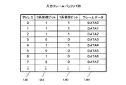
図12は、本発明の第1の実施形態の入力フレームバッファ136の説明図である。
FIG. 12 is an explanatory diagram of the
図12に示す本実施例の入力フレームバッファ136には、アドレス1361毎に、通信経路0系NW0からフレームを受信したか否かを示す0系受信ビット1362と、通信経路1系NW1からフレームを受信したか否かを示す1系受信ビット1363と、フレームデータ1364とが保持されている。アドレス1361の値は、シーケンス番号SNnow424の値と対応する。
In the
図12の例では、0系受信ビット1362の値‘1’は、通信経路0系NW0からフレームを受信したことを示す。1系受信ビット1363の値‘1’は、通信経路1系NW1からフレームを受信したことを示す。例えば、図12のアドレス1361の値‘6’に対応する0系受信ビット1362及び1系受信ビット1363の値は、それぞれ、‘1’及び‘0’である。これは、図12に示す入力フレームバッファ136を含むパケット転送装置が、シーケンス番号SNnow424として‘6’が設定されたフレームを、通信経路0系NW0から既に受信し、通信経路1系NW1からはまだ受信していないことを示す。この場合、フレームデータ1364の値DATA6には、通信経路0系NW0から受信したフレームの内容が格納される。
In the example of FIG. 12, the value “1” of the 0-
なお、フレームデータ1364に各フレームの内容であるデータ自体を格納する代わりに、そのデータが格納された位置を示すポインタが格納し、データ自体は別のフレームバッファに格納されてもよい。
Instead of storing the data itself that is the contents of each frame in the
再び図10を参照して、S202以降の処理を説明する。 Referring to FIG. 10 again, the processing after S202 will be described.
S202において、バッファ書込み処理部134は、受信したフレームのシーケンス番号SNnow424と同一のアドレス1361に対応する0系受信ビット1362、1系受信ビット1363及びフレームデータ1364を読み出す。
In S202, the buffer
バッファ書込み処理部134は、読み出した0系受信ビット1362、又は1系受信ビット1363の少なくとも一方が‘1’であるか否かを判定する(S203)。
The
S203において、どちらのビットも‘0’であると判定された場合、パケット転送装置は、今回受信したフレームと同一内容のフレームを、今回受信したフレームより前に、いずれの通信経路からも受信していない。例えば、図2の例においてパケット転送装置10NがSN:1であるフレーム301を受信した場合、パケット転送装置10Nはフレーム301より前にSN:1であるフレームを受信していないため、S203においてどちらのビットも‘0’であると判定される。
If it is determined in S203 that both bits are “0”, the packet transfer apparatus receives a frame having the same content as the currently received frame from any communication path before the currently received frame. Not. For example, in the example of FIG. 2, when the
この場合、バッファ書込み処理部134は、受信したフレームの装置内ヘッダ42から取得した入力ポートID421に対応する0系受信ビット1362又は1系受信ビット1363に‘1’を設定し、受信したフレームを装置内ヘッダ42とともにフレームデータ1364に格納する(S204)。具体的には、受信したフレームが通信経路0系NW0から受信したものである場合、0系受信ビット1362に‘1’が設定される。受信したフレームが通信経路1系NW1から受信したものである場合、1系受信ビット1363に‘1’が設定される。
In this case, the buffer
その後、バッファ書込み処理部134は、各フローID用のバッファ制御部131が保持するフレーム格納フラグ13Aに‘1’を設定し(S205)、処理を終了する(S207)。このフレーム格納フラグ13Aは、まだ送信要求されていないフレームが入力フレームバッファ136に格納されているか否かを示すフラグである。本実施形態では、フレーム格納フラグ13Aの値‘1’は、入力フレームバッファ136にフレームが格納されていることを示す。
Thereafter, the
一方、S203において、どちらかのビットが‘1’であると判定された場合、パケット転送装置10Nは、今回受信したフレームと同一内容のフレームを、今回受信したフレームより前に、いずれかの通信経路から既に受信している。例えば、図2の例においてパケット転送装置10NがSN:1であるフレーム311を受信した場合、パケット転送装置10Nはフレーム311より前にSN:1であるフレーム301を受信しているため、S203においてどちらかのビット(具体的には、0系受信ビット1362)が‘1’であると判定される。
On the other hand, if it is determined in S203 that one of the bits is “1”, the
この場合、今回受信したフレームと同一内容のフレームが既に入力フレームバッファ136に格納されている。このため、バッファ書込み処理部134は、フレームデータ1364を更新せず(すなわち、S202で読み出したフレームデータ1364の内容をそのまま入力フレームバッファ136に書き戻し)、入力ポートIDに対応する受信ビットに‘1’を設定し(S206)、シーケンス番号監視受信処理を終了する(S207)。
In this case, a frame having the same content as the frame received this time is already stored in the
上記S201の比較の結果、シーケンス番号SNnow424の値が読出しカウンタ13Bの値未満であると判定された場合、受信したフレームと同一内容のフレーム又はそれより後のフレームが既に送信要求されたと判定される。すなわち、受信したフレームを入力フレームバッファ136に格納する必要はもはやない。このため、バッファ書込み処理部134は、受信したフレームを廃棄して、シーケンス番号監視受信処理を終了する(S207)。
As a result of the comparison in S201, when it is determined that the value of the
図11は、本発明の第1の実施形態のバッファ書込み処理部134が実行するユーザデータ受信処理S300のフローチャートである。
FIG. 11 is a flowchart of user data reception processing S300 executed by the buffer
図11に示すユーザデータ受信処理S300が開始されると、バッファ書込み処理部134は、書込みカウンタ13Fの値を書込みアドレスとして、0系受信ビット1362及び1系受信ビット1363に‘1’を、フレームデータ1364に、装置内ヘッダ42を含む受信したフレームを格納する(S301)。
When the user data reception process S300 shown in FIG. 11 is started, the buffer
次に、バッファ書込み処理部134は、書込みカウンタ13Fを‘1’カウントアップし、フレーム格納フラグ13Aに‘1’を設定し(S302)、ユーザデータ受信処理を終了する(S303)。
Next, the buffer
なお、上記書込みカウンタ13Fは、入力フレームバッファ136への書込みアドレスとして使用される値を保持するカウンタであり、ユーザデータ受信処理S300においてのみ使用される。
The write counter 13F is a counter that holds a value used as a write address to the
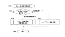
図13は、本発明の第1の実施形態のバッファ読出し処理部135が実行するフレーム送信要求処理S400のフローチャートである。
FIG. 13 is a flowchart of the frame transmission request process S400 executed by the buffer read
バッファ読出し処理部135は、フレーム格納フラグ13Aが‘0’から‘1’に変化したことを検知すると、設定レジスタ19の動作モードを確認する(S401)。その結果、動作モードが通信経路接続モードであると判定された場合、バッファ読出し処理部135は、図14及び図15に示すシーケンス番号順送信要求処理S500の処理を実行し、フレーム送信要求処理を終了する(S402)。一方、動作モードが端末接続モードであると判定された場合、バッファ読出し処理部135は、図16に示すユーザデータ送信要求処理S600の処理を実行し、フレーム送信要求処理を終了する(S402)。
When the buffer read
図14及び図15は、本発明の第1の実施形態のバッファ読出し処理部135が実行するシーケンス番号順送信要求処理S500のフローチャートである。
14 and 15 are flowcharts of the sequence number order transmission request processing S500 executed by the buffer read processing
図14及び図15に示すシーケンス番号順送信要求処理S500が開始されると、バッファ読出し処理部135は、フレーム格納フラグ13Aをクリア(すなわち‘0’に更新)する(S501)。
When the sequence number order transmission request processing S500 shown in FIGS. 14 and 15 is started, the buffer read processing
次に、バッファ読出し処理部135は、読出しカウンタ13Bの値を読出しアドレスとして入力フレームバッファ136からデータを読み出す(S502)。S502と並行して、バッファ読出し処理部135は、フローID13Cを検索キーとして用いて、図17に示す待ち時間保持テーブル21を検索する(S503)。
Next, the buffer read
なお、図14には、S502とS503が同時に実行される例を示すが、先にS502が実行され、その後S503が実行されてもよいし、先にS503が実行され、その後S502が実行されてもよい。 FIG. 14 shows an example in which S502 and S503 are executed at the same time. However, S502 may be executed first, and then S503 may be executed, or S503 is executed first, and then S502 is executed. Also good.
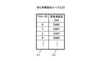
図17は、本発明の第1の実施形態の待ち時間保持テーブル21の説明図である。 FIG. 17 is an explanatory diagram of the waiting time holding table 21 according to the first embodiment of this invention.
本実施例では、上記待ち時間保持テーブル21には、フローID211毎に通信経路0系NW0と通信経路1系NW1の両系遅延差212が保持されている。この両系遅延差212は、フロー毎の通信経路設定時に測定された転送遅延時間の差であり、ネットワークの管理者によって設定される。
In this embodiment, the waiting time holding table 21 holds both
例えば、フローID#0用バッファ制御部131−1のバッファ読出し処理部135がS503を実行した場合、フローID211の値‘0’に対応する両系遅延差212の値‘Ddif0’がS503において取得される。
For example, when the buffer read processing
再び図14を参照して、S502及びS503に続く処理を説明する。 Referring to FIG. 14 again, the processing following S502 and S503 will be described.
上記S502及びS503の実行後、バッファ読出し処理部135は、S502において入力フレームバッファ136から読み出されたフレーム0系受信ビット1362及び1系受信ビット1363を確認する(S504)。その結果、どちらかの受信ビットに‘1’が保持されている場合、バッファ読出し処理部135は、入力フレームバッファ136の、読出しカウンタ13Bが示すアドレスにフレームが格納されている(すなわち、読出しカウンタ13Bの値と同じ値がシーケンス番号として付与されたフレームを既に受信している)と判定する。この場合、バッファ読出し処理部135は、フローID13C及び読出しカウンタ13Bの値とともに、送信要求をスケジューリング部132へ送信する(S505)。
After execution of S502 and S503, the buffer read processing
次に、バッファ読出し処理部135は、読出しカウンタ13Bを‘1’カウントアップする(S506)。
Next, the buffer read
次に、バッファ読出し処理部135は、残フレームカウンタ13Dの値がAll‘0’であるか否かを判定する(S507)。上記残フレームカウンタ13Dは、フレーム送信が一時的に停止した場合に、入力フレームバッファ136に蓄積された、まだ送信要求されていないフレームの数を示す。
Next, the buffer read
S507において、残フレームカウンタ13DがAll‘0’であると判定された場合、入力フレームバッファ136にまだ送信要求されていないフレームは蓄積されていないと判定される。この場合、バッファ読出し処理部135は、シーケンス番号順送信要求処理を終了する(S509)。
If it is determined in S507 that the remaining
一方、S507において、残フレームカウンタ13DがAll‘0’でないと判定された場合、入力フレームバッファ136にまだ送信要求されていないフレームが蓄積されている。この場合、バッファ読出し処理部135は、残フレームカウンタ13Dを‘1’カウントダウンする(S508)。これは、入力フレームバッファ136に蓄積された、まだ送信要求されていないフレームが、S505の実行の結果、一つ減ったためである。
On the other hand, if it is determined in S507 that the remaining
その後、バッファ読出し処理部135は、再度S502及びS503以降の処理を実行する。
Thereafter, the buffer read processing
一方、S504において、受信ビット1362及び1363がともに‘0’であった場合、バッファ読出し処理部135は、シーケンス番号に欠落が発生したと判定する。すなわち、この場合、二つの通信経路のうち一方で、フレーム損失が発生している。例えば、図2において、SN:2のフレーム302が損失し、パケット転送装置10Nが、SN:2のフレーム312を受信する前にSN:3のフレーム303を受信した場合、S504において、受信ビット1362及び1363の両方が‘0’であると判定される。
On the other hand, if the received
この場合、バッファ読出し処理部135は、損失したフレームと同一内容のフレームを残りの通信経路から受信するまで、フレームの送信を停止する。ただし、所定の時間(すなわちS503において取得された両系遅延差212)が経過しても損失したフレームと同一内容のフレームを受信しない場合、バッファ読出し処理部135は、二つの通信経路において同一内容のフレームが損失したと判定し、フレームの送信を再開する。そのために、バッファ読出し処理部135は、S503で取得した両系遅延差212を読出しタイマ13Eに設定し、カウントダウンを開始する(S510)。この読出しタイマ13Eは、シーケンス番号の欠落が発生した場合に、フレーム送信を再開するまでの待ち時間を計測するために使用される。タイマ13Eに設定された値は、カウントダウンが開始された後、時間の経過とともに減少し、最終的に‘0’になる。
In this case, the buffer read processing
次に、バッファ読出し処理部135は、読出しタイマ13EがAll‘0’であるか否かを判定する(S511)。
Next, the buffer read
読出しタイマ13EがAll‘0’でないと判定された場合、まだ待ち時間が経過していない。この場合、バッファ読出し処理部135は、フレーム格納フラグ13Aが‘1’か否かを判定する(S512)。その結果、フレーム格納フラグが‘1’であると判定された場合、読出しタイマ13Eが時間切れとなる(すなわち待ち時間が経過する)前に何らかのフレームが到着したと判定される。この場合、バッファ読出し処理部135は、読出しカウンタ13Bの値を読出しアドレスとして、入力フレームバッファ136を読み出し(S513)、0系受信ビット1362又は1系受信ビット1363が‘1’であるか否かを判定する(S514)。
If it is determined that the
その結果、0系受信ビット1362又は1系受信ビット1363の少なくとも一方が‘1’である場合、欠落したシーケンス番号のフレームが到着したと判定される。この場合、バッファ読出し処理部135は、フレーム格納フラグ13Aをクリアする(S520)。そして、バッファ読出し処理部135は、到着したシーケンス番号の送信要求を生成するため、S505以降の処理を実行する。
As a result, when at least one of the 0-
S514の結果、受信ビット1362及び受信ビット1363がともに‘0’である場合、欠落したシーケンス番号以外のシーケンス番号のフレームが到着している。この場合、バッファ読出し処理部135は、欠落したシーケンス番号の次のシーケンス番号のフレームが、二つの通信経路の両方から受信されているか否かを確認するため、読出しカウンタ13Bに‘1’を加算した値を読出しアドレスとして、入力フレームバッファ136を読み出す(S515)。そして、バッファ読出し処理部135は、受信ビット1362及び受信ビット1363がともに‘1’であるか否かを判定する(S516)。
If the received
その結果、受信ビット1362及び受信ビット1363がともに‘1’である場合、欠落したシーケンス番号のフレームは、二つの通信経路の両方において欠落したと判定される。この場合、バッファ読出し処理部135は、読出しカウンタ値13Bを‘1’カウントアップする(S519)。そして、バッファ読出し処理部135は、欠落したシーケンス番号の次のシーケンス番号が付与されたフレームの送信要求を生成するため、S520以降の処理を実行する。
As a result, when the
S516の結果、受信ビット1362及び受信ビット1363の少なくとも一方が‘0’である場合、欠落したシーケンス番号のフレームを待つ状態が継続される。このため、バッファ読出し処理部135は、フレーム格納フラグ13Aをクリアし(S517)、残フレームカウンタ13Dを‘1’カウントアップし(S518)、S511以降の処理を実行する。
As a result of S516, when at least one of the
S511の結果、読出しタイマ13EがAll‘0’である場合、欠落したシーケンス番号のフレームは二つの通信経路の両方において損失したと判定される。この場合、バッファ読出し処理部135は、欠落したシーケンス番号の次のシーケンス番号のフレームの送信要求を生成するため、S506以降の処理を実行する。その結果、欠落したシーケンス番号の次以降のシーケンス番号が付与されたフレームの送信が再開される。
As a result of S511, when the
上記S512の結果、フレーム格納フラグが‘0’であると判定された場合、欠落したシーケンス番号のフレームを待つ状態が継続される。このため、バッファ読出し処理部135は、S511以降の処理を実行する。
As a result of S512, when it is determined that the frame storage flag is “0”, the state of waiting for the frame with the missing sequence number is continued. For this reason, the buffer read processing
例えば、図2において、SN:2のフレーム302が損失し、パケット転送装置10NがSN:3のフレーム303を受信した後、両系遅延差81が経過する前にSN:2のフレーム312を受信した場合、S511において読出しタイマ13EがAll‘0’でないと判定される。そして、S512においてフレーム格納フラグ13Aが‘1’であると判定される。そして、S514において、1系受信ビット1363が‘1’であると判定される。
For example, in FIG. 2, the SN: 2
図2の例において、さらにSN:2のフレーム312が損失し、両系遅延差81が経過する前にパケット転送装置10NがSN:3のフレーム313を受信した場合、S511において読出しタイマ13EがAll‘0’でないと判定される。そして、S512においてフレーム格納フラグ13Aが‘1’であると判定される。そして、S514において、0系受信ビット1362及び1系受信ビット1363がいずれも‘0’であると判定される。そして、S516において、0系受信ビット1362及び1系受信ビット1363がいずれも‘1’であると判定される。
In the example of FIG. 2, when the SN: 2
図2の例において、パケット転送装置10NがSN:2のフレーム312及びSN:3のフレーム313のいずれも受信しないうちに両系遅延差81が経過した場合、S511において読出しタイマ13EがAll‘0’であると判定される。
In the example of FIG. 2, when the two-
図16は、本発明の第1の実施形態のバッファ読出し処理部135が実行するユーザデータ送信要求処理S600のフローチャートである。
FIG. 16 is a flowchart of user data transmission request processing S600 executed by the buffer read processing
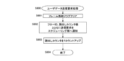
図16に示すユーザデータ送信要求処理S600が開始されると、バッファ読出し処理部135は、フレーム格納フラグ13Aをクリアする(S601)。
When the user data transmission request process S600 shown in FIG. 16 is started, the buffer read processing
次に、バッファ読出し処理部135は、フローID13C及び読出しカウンタ13Bの値とともに、スケジューリング部132へ送信要求を送信する(S602)。
Next, the buffer read processing
次に、バッファ読出し処理部135は、読出しカウンタ13Bの値を‘1’カウントアップし(S603)、ユーザデータ送信要求処理を終了する(S604)。
Next, the buffer read
上記のように、ユーザデータ送信要求処理S600は、ユーザデータ受信処理S300が入力フレームバッファ136に順次格納したフレームを、アドレスの順に読み出すことによって実現することができる。
As described above, the user data transmission request process S600 can be realized by reading the frames sequentially stored in the
フローチャートは図示しないが、スケジューリング部132は、バッファ読出し処理部135から上記送信要求を受信すると、受信した送信要求を、同時に通知されるフローID及び読出しカウンタ値とともに送信要求格納FIFO137に格納し、各フローID用バッファ制御部131からの送信要求を多重する。そして、スケジューリング部132は、送信要求格納FIFO137から送信要求を一つずつ読み出し、送信要求格納FIFO137から読み出されたフローIDに該当するフローID用バッファ制御部131―iに対して、送信許可及び読出しカウンタ値を通知する。
Although the flowchart is not shown, when the
図18は、本発明の第1の実施形態のバッファ読出し処理部135が実行するフレーム送信処理S700のフローチャートである。
FIG. 18 is a flowchart of a frame transmission process S700 executed by the buffer read processing
バッファ読出し処理部135は、スケジューリング部132から上記送信許可を受信すると、この送信許可と同時に送信される読出しカウンタ値を取得する(S701)。
When the buffer read processing
次に、バッファ読出し処理部135は、取得した読出しカウンタ値をアドレスとして、入力フレームバッファ136からフレームを読み出し、その後、当該アドレスのエントリにAll‘0’を上書きする(S702)。
Next, the buffer read
次に、バッファ読出し処理部135は、設定レジスタ19の動作モードを確認する(S703)。
Next, the buffer read processing
動作モードが通信経路接続モードであると判定された場合、S702において読み出されたフレームは、通信経路0系NW0又は通信経路1系NW1の少なくとも一方を介して別のパケット転送装置に送信されるべきフレームである。この場合、バッファ読出し処理部135は、装置内ヘッダ42のコピービット425を確認する(S704)。
When it is determined that the operation mode is the communication path connection mode, the frame read in S702 is transmitted to another packet transfer apparatus via at least one of the
S704において、コピービット425が‘0’であると判定された場合、読み出されたフレームのコピーを生成する必要がない。このため、バッファ読出し処理部135は、装置内ヘッダ42のフレーム長426の分だけ、入力フレームバッファ136から読み出したフレームデータ1364を送信する(S705)。
If it is determined in S704 that the
次に、バッファ読出し処理部135は、スケジューリング部132へ送信完了を通知して(S708)、フレーム送信処理を終了する(S709)。
Next, the buffer read processing
一方、S704において、装置内ヘッダ42のコピービット425が‘1’であると判定された場合、読み出されたフレームのコピーを作成する必要がある。このため、バッファ読出し処理部135は、フローID13Cを検索キーとして、図19に示すコピー作成テーブル22を検索する(S706)。この検索の結果、バッファ読出し処理部135は、コピーされたフレームに付与されるヘッダ情報を取得する。
On the other hand, if it is determined in S704 that the
図19は、本発明の第1の実施形態のコピー作成テーブル22の説明図である。 FIG. 19 is an explanatory diagram of the copy creation table 22 according to the first embodiment of this invention.
コピー作成テーブル22は、コピーしたフレームに付与するヘッダに関する情報を保持する。すなわち、コピー作成テーブル22は、フローID221を検索キーとして、MPLSラベル222、出力NIF ID223、出力ポートID224、送信元MACアドレス205及び宛先MACアドレス226を示すテーブルエントリを検索するためのものである。ここで、送信元MACアドレス225は、出力ポートID224によって識別される入出力回線インタフェース11−iに付与されたMACアドレスである。宛先MACアドレス226は、上記入出力回線インタフェース11−iを介して接続された、フレームの宛先となるパケット転送装置のMACアドレスを示す。
The copy creation table 22 holds information regarding the header added to the copied frame. That is, the copy creation table 22 is used to search for a table entry indicating the
再び図18を参照して、S706に続く処理を説明する。 With reference to FIG. 18 again, the processing following S706 will be described.
上記S706において、コピーされたフレームに付与するヘッダ情報を取得した後、バッファ読出し処理部135は、S705のフレーム送信処理と同様にフレームを送信するとともに、そのフレームのコピーを作成して、作成されたフレームを送信する(S707)。
After acquiring the header information to be added to the copied frame in S706, the buffer read processing
具体的には、バッファ読出し処理部135は、S705のフレーム送信処理と同様にフレームを送信する。さらに、バッファ読出し処理部135は、送信されるフレームのコピーを作成する。バッファ読出し処理部135は、コピーとして作成されたフレームのMACヘッダ中の宛先MACアドレス411、送信元MACアドレス412及びMPLSヘッダ414に、S706においてコピー作成テーブルから取得した宛先MACアドレス226、送信元MACアドレス225及びMPLSラベル222を上書きする。さらに、バッファ読出し処理部135は、コピーとして作成されたフレームの装置内ヘッダ42の出力NIF ID427及び出力ポートID422に、S706においてコピー作成テーブルから取得した出力NIF ID223及び出力ポートID224を上書きする。さらに、バッファ読出し処理部135は、コピーとして作成されたフレームの入力ポートID421を反転させる。そして、バッファ読出し処理部135は、装置内ヘッダ42のフレーム長426の分だけ読み出したフレームを送信する。
Specifically, the buffer read processing
S707において入力ポートID421を反転させるのは、オリジナルフレームが使用していない方のポートにコピーフレームを送信する必要があるためである。フレーム振分け部133は、入力ポートID421に対応したSWインタフェース14にフレームを送信する。このため、バッファ読出し処理部135がS707において入力ポートID421を反転させると、フレーム振分け部133は、コピーとして作成されたフレームを空いているポートに振り分ける。
The reason why the
その後、バッファ読出し処理部135は、スケジューリング部132へ送信完了を通知して(S708)、フレーム送信処理を終了する(S709)。
Thereafter, the buffer read processing
上記S703において、設定レジスタ19の動作モードが端末接続モードであると判定された場合、バッファ読出し処理部135は、フローID13Cを用いて図20に示す送信SNテーブル23を検索する(S710)。
If it is determined in S703 that the operation mode of the setting
図20は、本発明の第1の実施形態の送信SNテーブル23の説明図である。 FIG. 20 is an explanatory diagram of the transmission SN table 23 according to the first embodiment of this invention.
図20の送信SNテーブル23は、フローID231を検索キーとして、送信するフレームのシーケンス番号フィールド415に付与される送信シーケンス番号232を検索するためのテーブルである。すなわち、送信シーケンス番号232には、各フローにおいて次回送信されるフレームに付与されるべきシーケンス番号が保持される。バッファ読出し処理部135は、S710を実行することによって、これから送信しようとするフレームに付与すべきシーケンス番号を取得する。
The transmission SN table 23 in FIG. 20 is a table for searching for the
上記S710の後、バッファ読出し処理部135は、送信SNテーブルから取得した送信シーケンス番号232を、フレームのシーケンス番号フィールド415に上書きする(S711)。そして、バッファ読出し処理部135は、テーブルから取得した送信シーケンス番号232に‘1’を加算した値を、送信SNテーブル23の該当エントリに書き戻す(S712)。
After S710, the buffer read
その後、バッファ読出し処理部135は、上記シーケンス番号を上書きしたフレームを送信するため、装置内ヘッダ42のコピービット425の判定処理S704以降の処理を実行する。
Thereafter, the buffer read processing
以上に説明したように、本発明の第1の実施形態のパケット転送装置は、一つの通信経路においてフレームが損失した場合、損失したフレームと同一内容のフレームを他の通信経路から受信するのを待つ。損失したフレームと同一内容のフレームを受信した場合、そのフレームを転送することによって、フレームの損失を防ぐことができる。さらに、本発明の第1の実施形態のパケット転送装置は、一つの通信経路において損失したフレームと同一内容のフレームを他の通信経路からまだ受信していない場合であっても、所定の条件に基づいて、損失したフレームより後のフレームの転送を再開する。これによって、本発明の第1の実施形態のパケット転送装置は、転送できるフレームを保持しているにもかかわらずフレーム転送を再開できなくなることを防ぐことができる。 As described above, the packet transfer apparatus according to the first exemplary embodiment of the present invention receives a frame having the same content as the lost frame from another communication path when a frame is lost in one communication path. wait. When a frame having the same content as the lost frame is received, the loss of the frame can be prevented by transferring the frame. Furthermore, the packet transfer apparatus according to the first exemplary embodiment of the present invention satisfies a predetermined condition even when a frame having the same content as a frame lost in one communication path has not yet been received from another communication path. Based on this, the transfer of frames after the lost frame is resumed. Thereby, the packet transfer apparatus according to the first embodiment of the present invention can prevent the frame transfer from being unable to be resumed even though the transferable frame is held.
次に、本発明の第2の実施形態について説明する。 Next, a second embodiment of the present invention will be described.
図21は、本発明の第2の実施形態のパケット転送装置10Nの動作の概要を示す説明図である。
FIG. 21 is an explanatory diagram showing an outline of the operation of the
図21と、図2との相違は、パケット転送装置10Nが、欠落したシーケンス番号のフレームを待つ時間の設定方法と、設定する値の内容である。以下、図21が図2と相違する点について説明する。図21の説明のうち、図2の説明と同様の部分は記載を省略する。
The difference between FIG. 21 and FIG. 2 is the setting method of the time for which the
図21では、パケット転送装置10Nは、まだいずれの通信経路からも受信していないシーケンス番号(SN)が付与されたフレームを受信する度に、両系遅延差81及び平均フレーム間隔(すなわちフレーム間隔の平均値)82をタイマ(図23参照)に設定し、カウントダウンを開始する。平均フレーム間隔82は、パケット転送装置10Nが監視する各フローのフレームの受信間隔の平均値である。
In FIG. 21, every time the
通常、フレームの損失がなければ、このタイマはフレーム受信の度に更新され、受信したフレームは直ちに送信される。しかし、フレーム(例えば、通信経路0系MW0から受信するはずのSN:2のフレーム302)が損失し、シーケンス番号の欠落を検出すると、パケット転送装置10Nは、タイマを更新せず、フレームの送信を一時停止する。そして、上記タイマが‘0’になった時点、又は、片方の系で損失したSN:2のフレーム312を受信した時点、又は、両系からSN:3のフレームを受信した時点で、パケット転送装置10Nは、フレームの送信を再開する。
Normally, if there is no frame loss, this timer is updated each time a frame is received, and the received frame is transmitted immediately. However, when a frame (for example, SN: 2
具体的には、パケット転送装置10Nは、SN:2のフレーム302を受信する前にSN:3のフレーム303を受信した場合、通信経路0系MW0においてフレーム302が損失したと判定する。パケット転送装置10Nは、タイマが‘0’になる前に、損失したフレームと同一内容のSN:2のフレーム312を通信経路1系NW1から受信した場合、フレーム312を送信する。パケット転送装置10Nは、タイマが‘0’になる前、かつ、SN:2のフレーム312を受信する前に、SN:3のフレーム313を通信経路1系NW1から受信した場合、SN:3のフレーム303又はフレーム313を送信する。パケット転送装置10Nは、SN:2のフレーム312又はSN:3のフレーム313のいずれも受信しないうちにタイマが‘0’になった場合、SN:3のフレーム303を送信する。
Specifically, when receiving the SN: 3
図22は、本発明の第2の実施形態のパケット転送装置10Nの動作の変形例を示す説明図である。
FIG. 22 is an explanatory diagram illustrating a modified example of the operation of the
図22では、タイマに平均フレーム間隔82の代わりに、フレーム間隔の最大値(すなわち最大フレーム間隔)83が設定される。図22のそれ以外の点は、図21と同様である。上記最大フレーム間隔83は、パケット転送装置10Nが監視する各フローのフレームの受信間隔の最大値である。
In FIG. 22, instead of the
図21に示す方法は、平均値に基づいて待ち時間を決定するため、フレーム揺らぎが小さいTDMエミュレーション又はVoIPトラヒックと、入り口でシェーパなどの帯域調整を行ったストリーミングトラヒックとの混在ネットワークに適している。 The method shown in FIG. 21 is suitable for a mixed network of TDM emulation or VoIP traffic with small frame fluctuations and streaming traffic with bandwidth adjustment such as a shaper at the entrance because the waiting time is determined based on the average value. .
一方、図22に示す方法は、フレーム揺らぎが極端に大きいトラヒックにも対応可能である。ただし、いわゆるストリームの切れ目である、トラヒックが到着しない期間が、最大フレーム間隔83として設定されることを排除する必要がある。そのため、各パケット転送装置が一つの最大値を持ってもよいし、現在の最大値の一定倍以上大きい最大値は許容されなくてもよい。
On the other hand, the method shown in FIG. 22 can cope with traffic with extremely large frame fluctuations. However, it is necessary to exclude that a period during which traffic does not arrive, which is a so-called stream break, is set as the
以上のように、図21及び図22の方式をフロー毎のトラヒックの特性に合わせて適用することによって、異なる特性のトラヒックが混在した場合にも本発明を適用することができる。 As described above, by applying the method of FIGS. 21 and 22 according to the traffic characteristics for each flow, the present invention can be applied even when traffic of different characteristics coexists.
また、図21及び図22に示す方法によれば、図2と同様に、仮に通信経路1系NW1のSN:3のフレーム313が損失した場合、及び、片側の通信経路に回線障害が発生した場合にも、フレームの送信が完全に停止することなく、フレームの損失を防止することができる。
Further, according to the method shown in FIG. 21 and FIG. 22, as in FIG. 2, if the SN: 3
さらに、図2に示す方法によれば、パケット転送装置は、テーブルに設定された固定遅延分だけフレームを待っていた。このため、実際のネットワークの使用状況又は設定による遅延の変動に対応することができなかった。しかし、図21及び図22に示す方法によれば、過去のトラヒックの履歴がフレームの待ち時間に反映される。このため、上記のようなネットワーク使用状況の変化に自動的に対応することができる。 Further, according to the method shown in FIG. 2, the packet transfer apparatus waits for the frame by the fixed delay set in the table. For this reason, it has not been possible to cope with delay variations due to actual network usage or settings. However, according to the method shown in FIGS. 21 and 22, the past traffic history is reflected in the frame waiting time. Therefore, it is possible to automatically cope with the change in the network usage situation as described above.
本実施形態のパケット転送装置10Nの構成は、第1の実施形態の図5と同様であるが、入力フレームバッファ制御部13のみ、その構成と機能が第1の実施形態と異なる。以下、第2の実施形態が第1の実施形態と相違する点について説明する。
図23は、本発明の第2の実施形態の入力フレームバッファ制御部13の構成を示すブロック図である。
The configuration of the
FIG. 23 is a block diagram illustrating a configuration of the input frame
入力フレームバッファ制御部13は、各フローID用のバッファ制御部1301(すなわち1301−1〜1301−n)、これらの各フローID用バッファ制御部1301に接続されたスケジューリング部132、及び、上記各フローID用バッファ制御部1301と接続されたフレーム振分け部133を備える。
The input frame
各フローID用バッファ制御部1301は、バッファ書込み処理部1304、バッファ読出し処理部1305及び入力フレームバッファ136を備える。
Each flow
さらに、各フローID用バッファ制御部1301は、フレーム格納フラグ130A、読出しカウンタ130B、フローID130C、残フレームカウンタ130D、読出しタイマ130E、書込みカウンタ130F、送信停止フラグ130G、送信停止シーケンス番号(SN)130H及び時刻カウンタ130Jを保持する。
Further, each flow
フレーム格納フラグ130A、読出しカウンタ130B、フローID130C、残フレームカウンタ130D、読出しタイマ130E及び書込みカウンタ130Fは、それぞれ、第1の実施形態のフレーム格納フラグ13A、読出しカウンタ13B、フローID13C、残フレームカウンタ13D、読出しタイマ13E及び書込みカウンタ13Fと同様である。
The
送信停止フラグ130Gは、フレームの送信を停止するか否かを示すフラグである。
The
送信停止SN130Hは、送信停止SN130Hには、欠落したシーケンス番号の一つ前のシーケンス番号(すなわち、送信が停止する以前、最後に送信されたフレームのシーケンス番号)を保持する。 The transmission stop SN 130H holds the sequence number immediately before the missing sequence number in the transmission stop SN 130H (that is, the sequence number of the last frame transmitted before the transmission stopped).
時刻カウンタ130Jは、現在の時刻を保持するカウンタである。
The
入力フレームバッファ136の構成は、第1の実施形態と同様である(図12参照)。
The configuration of the
バッファ書込み処理部1304は、入力ヘッダ処理部12からフレームを受信すると、受信したフレームの装置内ヘッダ42のフローID423を参照する。フローID423が、自バッファ制御部1301が割り当てられたフローの識別子でない場合、バッファ書込み処理部1304は、受信したフレームを破棄する。フローID423が、自バッファ制御部1301が割り当てられたフローの識別子である場合、バッファ書込み処理部1304は、受信したフレームを対象として、設定レジスタ19の動作モードに従ってバッファ書込み処理S100を実行する。その結果、受信したフレームが順次バッファ136に格納される。
When the buffer
バッファ読出し処理部1305は、設定レジスタ19の動作モードに従ってフレーム送信要求処理S400を実行する。その結果、自バッファ制御部1301が割り当てられたフローのID情報を含む送信要求がスケジューリング部132に送信される。
The buffer read
上記送信要求を受信したスケジューリング部132は、送信要求を送信要求格納FIFO137に一旦格納する。スケジューリング部132は、送信要求格納FIFO137から順次送信要求を読み出す。そして、スケジューリング部132は、読み出された送信要求の送信元であるフローID用バッファ制御部1301に対して、送信許可を送信する。
The
上記送信許可を受信したバッファ読出し処理部1305は、入力フレームバッファ136からフレームを読み出し、フレーム振分け部133に出力する。
The buffer read
フレーム振分け部133は、バッファ読出し処理部1305からフレームを受信すると、装置内ヘッダ42の中の入力ポートID421を参照し、入力ポートID421に対応するSWインタフェース14を選択し、選択されたSWインタフェース14にフレームを転送する。入出力回線インタフェース11とSWインタフェース14の対応関係は、第1の実施形態と同様である(図5の説明参照)。
When receiving a frame from the buffer
第2の実施形態のバッファ書込み処理部1304は、第1の実施形態のバッファ書込み処理部134と同様、図9に示すバッファ書込み処理S100を実行する。ただし、第2の実施形態のバッファ書込み処理部1304は、シーケンス番号監視受信処理S200の代わりに、図24に示すシーケンス番号監視受信処理S800を実行する。
Similarly to the buffer
図24は、本発明の第2の実施形態のバッファ書込み処理部1304が実行するシーケンス番号監視受信処理S800のフローチャートである。
FIG. 24 is a flowchart of the sequence number monitoring reception process S800 executed by the buffer
図24に示すシーケンス番号監視受信処理S800が開始されると、バッファ書込み処理部1304は、受信したフレームの装置内ヘッダ42から取得したシーケンス番号SNnow424と、各フロー用バッファ制御部131が保持している読出しカウンタ130Bの値とを比較する(S801)。読出しカウンタ130Bは、入力フレームバッファ136の読出しアドレスを示している。
When the sequence number monitoring reception process S800 shown in FIG. 24 is started, the buffer
バッファ書込み処理部1304は、シーケンス番号SNnow424を入力フレームバッファ136への書込みアドレスとして使用する。このため、上記読出しカウンタ130Bの値とシーケンス番号SNnowとを比較することによって、受信したフレームと同一内容のフレームが既に送信要求されているか否かを判定することができる。
The buffer
上記S801の比較の結果、シーケンス番号SNnow424の値が読出しカウンタ130Bの値以上であると判定された場合、受信したフレームと同一内容のフレームがまだ送信要求されていない。すなわち、受信したフレームと同一内容のフレームがまだ入力フレームバッファ136に格納されていない可能性がある。この場合、バッファ書込み処理部1304は、受信したフレームのシーケンス番号SNnow424の値を読出しアドレスとして、図12に示す入力フレームバッファ136を読み出す(S802)。この読出しの手順は、図10のS202と同様である。
As a result of the comparison in S801, if it is determined that the value of the
次に、バッファ書込み処理部1304は、読み出した0系受信ビット1362、又は1系受信ビット1363の少なくとも一方が‘1’であるか否かを判定する(S803)。
Next, the
S803において、どちらのビットも‘0’であると判定された場合、バッファ書込み処理部1304は、受信したフレームの装置内ヘッダ42から取得した入力ポートID421に対応する0系受信ビット1362又は1系受信ビット1363に‘1’を設定し、受信したフレームを装置内ヘッダ42とともにフレームデータ1364に格納する(S804)。
If it is determined in S803 that both bits are '0', the buffer
その後、バッファ書込み処理部1304は、各フローID用のバッファ制御部1301が保持するフレーム格納フラグ130Aに‘1’を設定する(S805)。
Thereafter, the buffer
さらに、バッファ書込み処理部1304は、上記フレーム格納処理S804と並行して、待ち時間更新処理S900を実行する。図24には、待ち時間更新処理S900がフレーム格納処理S804と並行して実行される例を示すが、待ち時間更新処理S900は、S804の前に実行されてもよいし、S804又はS805の後に実行されてもよい。
Further, the buffer
S805及びS900がいずれも終了すると、バッファ書込み処理部1304は、シーケンス番号監視受信処理を終了する(S807)。
When both S805 and S900 are completed, the buffer
一方、S803において、どちらかのビットが‘1’であると判定された場合、今回受信したフレームと同一内容のフレームが既に入力フレームバッファ136に格納されている。このため、バッファ書込み処理部1304は、フレームデータ1364を更新せず(すなわち、S802で読み出したフレームデータ1364の内容をそのまま入力フレームバッファ136に書き戻し)、入力ポートIDに対応する受信ビットに‘1’を設定し(S806)、シーケンス番号監視受信処理を終了する(S807)。
On the other hand, if it is determined in S803 that one of the bits is “1”, a frame having the same content as the frame received this time is already stored in the
上記S801の比較の結果、シーケンス番号SNnow424の値が読出しカウンタ130Bの値未満であると判定された場合、受信したフレームと同一内容のフレーム又はそれより後のフレームが既に送信要求されたと判定される。すなわち、受信したフレームを入力フレームバッファ136に格納する必要はもはやない。このため、バッファ書込み処理部1304は、受信したフレームを廃棄して、シーケンス番号監視受信処理を終了する(S807)。
As a result of the comparison in S801, when it is determined that the value of the
図25及び図26は、本発明の第2の実施形態のバッファ書込み処理部1304が実行する待ち時間更新処理S900のフローチャートである。
25 and 26 are flowcharts of the waiting time update process S900 executed by the
バッファ書込み処理部1304は、フローID130Cを用いて、待ち時間保持テーブル21を検索する(S901)。
The buffer
図27は、本発明の第2の実施形態の待ち時間保持テーブル21の説明図である。 FIG. 27 is an explanatory diagram of the waiting time holding table 21 according to the second embodiment of this invention.
本実施形態の待ち時間保持テーブル21は、フローID211毎に、通信経路0系NW0と1系NW1の両系遅延差Ddif212、算出モードMode213、前回シーケンス番号SNpre214、前回到着時刻Tpre215、フレーム間隔IFG216及び時刻カウンタ週回数TRap217を保持するテーブルである。
The waiting time holding table 21 according to the present embodiment includes, for each
両系遅延差Ddif212は、図17に示すものと同様のものである。 Both system delay differences Ddif212 are the same as those shown in FIG.
算出モードMode213は、フレーム間隔IFGの算出方法を表す。算出モードMode213の値‘0’は、過去のフレーム間隔の平均値がフレーム間隔IFGとして算出されることを示す。‘1’は、過去のフレーム間隔の最大値がフレーム間隔IFGとして算出されることを示す。算出された値は、フレーム間隔IFG216に保持される。
The
前回シーケンス番号SNpre214、前回到着時刻Tpre215及びフレーム間隔IFG216は、フレーム受信の度に更新されるフィールドである。前回シーケンス番号SNpre:214には、受信したフレームのシーケンス番号が上書きされる。前回到着時刻Tpre215には、フレームを受信した時点の時刻カウンタ130Jの値が上書きされる。フレーム間隔IFG216には、算出モードMode213に従って算出されたフレーム間隔が上書きされる。
The previous sequence number SNpre214, the previous arrival time Tpre215, and the frame interval IFG216 are fields that are updated each time a frame is received. The previous sequence number SNpre: 214 is overwritten with the sequence number of the received frame. The value of the
時刻カウンタ週回数TRap217は、前回テーブルを更新してから現在までに何回時刻カウンタ130Jが最大値から‘0’に戻ったかを示す。ここで、時刻カウンタ130Jは、現在の時刻を保持するカウンタである。時刻カウンタ130Jに保持された時刻は、パケット転送装置の動作周波数クロックに従って、クロックごとにカウントアップされる。
The time counter
再び図25を参照して、S901に続く処理を説明する。 With reference to FIG. 25 again, the processing following S901 will be described.
バッファ書込み処理部1304は、S901においてテーブル値を検索する。その結果、バッファ書込み処理部1304は、そのバッファ書込み処理部1304が属するバッファ制御部1301が割り当てられたフローの識別子がフローID211に対応するテーブル値を取得する。さらに、バッファ書込み処理部1304は、時刻カウンタ130Jの値を、今回フレームを受信した時刻すなわち今回到着時刻Tnowとして保持する(S902)。
The buffer
次に、バッファ書込み処理部1304は、受信したフレームの装置内ヘッダ42のシーケンス番号SNnow424の値が、S902において取得した前回シーケンス番号SNpre214に‘1’を加算した値に等しいか否かを判定する(S903)。
Next, the buffer
S903において、シーケンス番号SNnow424の値が前回シーケンス番号SNpre214に‘1’を加算した値に等しいと判定された場合、バッファ書込み処理部1304は、S902において取得した時刻カウンタ週回数TRap217の値を確認する(S904)。
In S903, when it is determined that the value of the
S904からS908は、今回受信したフレームと前回受信したフレームとのフレーム間隔を算出する処理である。フレーム間隔は、原則として、時刻カウンタ130Jから取得された今回到着時刻Tnowから、前回到着時刻Tpre215を減算することによって算出することができる。しかし、時刻カウンタ130Jの桁数は有限であるため、時刻カウンタ130Jの値は、最大値の次に‘0’に戻り、その後順次カウントアップされる。このとき、時刻カウンタ週回数TRap217の値が‘1’加算される。したがって、フレーム間隔は、今回到着時刻Tnow、前回到着時刻Tpre215及び時刻カウンタ週回数TRap217に基づいて算出される必要がある。
S904 to S908 are processes for calculating the frame interval between the frame received this time and the frame received last time. In principle, the frame interval can be calculated by subtracting the previous arrival time Tpre215 from the current arrival time Tnow acquired from the
S904において、時刻カウンタ週回数TRap217が‘0’であると判定された場合、前回フレームを受信した後、時刻カウンタ130Jの値は最大値に達していない。この場合、バッファ書込み処理部1304は、Tnowから前回到着時刻Tpre215を減算した値をフレーム間隔IFGnowとして保持する(S905)。
If it is determined in S904 that the time counter weekly number TRap217 is “0”, the value of the
S904において、時刻カウンタ週回数TRap217が‘1’であると判定された場合、前回フレームを受信した後、時刻カウンタ130Jの値が一度最大値に達し、‘0’に戻っている。この場合、バッファ書込み処理部1304は、時刻カウンタ130Jの値Tnowが前回到着時刻Tpre215より大きいか否かを判定する(S906)。
If it is determined in S904 that the time counter weekly number TRap217 is “1”, the value of the
S906において、時刻カウンタ130Jの値Tnowが前回到着時刻Tpre215以下であると判定された場合、バッファ書込み処理部1304は、時刻カウンタ130Jの最大値Tmaxから前回到着時刻Tpre215を減算した値を、Tnowに加算する。そして、バッファ書込み処理部1304は、その加算の結果得られた値をフレーム間隔IFGnowとして保持する(S907)。
In S906, when it is determined that the value Tnow of the
S906において、時刻カウンタ130Jの値Tnowが前回到着時刻Tpre215より大きいと判定された場合、及び、S904において、時刻カウンタ週回数TRapが‘2’以上であると判定された場合、実際のフレーム間隔は、Tmaxより大きい。この場合、バッファ書込み処理部1304は、Tmaxをフレーム間隔IFGnowとして保持する(S908)。ここで、Tmaxをネットワークとして許容できる最大の遅延時間以上にする必要がある。
If it is determined in S906 that the value Tnow of the
上記S905、S907又はS908の後、バッファ書込み処理部1304は、算出モードMode213を確認する(S911)。
After S905, S907, or S908, the
S911において、算出モードMode213が‘0’であると判定された場合、フレーム間隔の平均値が、フレーム間隔IFG216として設定される。この場合、バッファ書込み処理部1304は、フレーム間隔の平均値を算出するため、(IFGnow+IFG216)÷2を、平均フレーム間隔(IFGave)として算出する(S912)。そして、バッファ書込み処理部1304は、算出されたIFGaveを、待ち時間保持テーブル21に書き戻される値IFGとして保持する(S913)。
If it is determined in S911 that the
S911において、算出モードMode213が‘1’であると判定された場合、フレーム間隔の最大値が、フレーム間隔IFG216として設定される。この場合、バッファ書込み処理部1304は、フレーム間隔の最大値を算出するため、max(IFGnow、IFG216)を、最大フレーム間隔(IFGmax)として算出する(S914)。ここで、max(A、B)は、AとBのうち大きい方を選択する、という意味の関数である。さらにこの関数の条件として、ある一定の値以上の値は選択しない、又は、Bの一定倍以上の値は選択しない、などの条件を付加してもよい。これによって、トラヒックの切れ目において、IFGnowが非常に大きい場合に、そのIFGnowの値を排除することができる。
When it is determined in S911 that the
その後、バッファ書込み処理部1304は、算出されたIFGmaxを、待ち時間保持テーブル21に書き戻される値IFGとして保持する(S915)。
Thereafter, the buffer
上記S904と並行して、バッファ書込み処理部1304は、各フローID用バッファ制御部1301が保持する送信停止フラグ130Gを確認する(S909)。
In parallel with S904, the
S909において、送信停止フラグ130Gが‘0’であると判定された場合、バッファ書込み処理部1304は、取得したフレーム間隔IFG216に両系遅延差Ddif212を加算した値を、読出しタイマ130Eに設定し、読出しタイマ130Eのカウントダウンを開始する(S910)。送信停止フラグ130Gは、バッファ書込み処理部1304が、シーケンス番号の欠落を検出した際に‘1’に設定するフラグである。送信停止フラグ130Gが‘1’である間、フレームの送信を停止して、欠落したシーケンス番号が付与されたフレームの受信を待つ処理が必要となる。
If it is determined in S909 that the
バッファ書込み処理部1304は、S910が実行された後、待ち時間更新処理を終了する(S919)。
The buffer
上記S909の確認の結果、送信停止フラグ130Gが‘1’であると判定された場合、バッファ書込み処理部1304は、読出しタイマ130Eを更新せず、待ち時間更新処理を終了する(S919)。
As a result of the confirmation in S909, when it is determined that the
図25には、S909からS910の処理が、S904からS908及びS911からS916の処理と並行して実行される例を示す。しかし、S909からS910の処理は、S904の前に実行されてもよいし、S916の後に実行されてもよい。すなわち、S909からS910の処理が実行された後にS904が実行されてもよいし、S916の処理が実行された後にS909が実行されてもよい。 FIG. 25 illustrates an example in which the processes from S909 to S910 are executed in parallel with the processes from S904 to S908 and S911 to S916. However, the processing from S909 to S910 may be executed before S904 or may be executed after S916. That is, S904 may be executed after the processes of S909 to S910 are executed, or S909 may be executed after the process of S916 is executed.
上記S903において、シーケンス番号SNnow424の値と、前回シーケンス番号SNpre214に‘1’を加算した値が等しくないと判定された場合、フレームの損失によってシーケンス番号の欠落が発生したと判定される。この場合、バッファ書込み処理部1304は、待ち時間保持テーブルに書き戻される値IFGとして、S902において取得されたフレーム間隔IFG216を保持する(S917)。
In S903, when it is determined that the value of the
上記S913、S915又はS917の処理の後、バッファ書込み処理部1304は、待ち時間保持テーブル21を更新する(S916)。具体的には、バッファ書込み処理部1304は、S902において取得されたテーブル値のうち、前回シーケンス番号SNpre214に、SNnow424の値を書き戻し、前回到着時刻Tpre215に、現在の時刻カウンタ130Jの値Tnowを書き戻し、フレーム間隔IFG216に、書き戻し値IFGを書き戻し、時刻カウンタ周回数TRapに、‘0’を書き戻す。
After the process of S913, S915, or S917, the buffer
S916の処理が終了すると、バッファ書込み処理部1304は、待ち時間更新処理を終了する(S919)。
When the process of S916 ends, the
上記S917の処理と並行して、バッファ書込み処理部1304は、送信停止フラグ130Gに‘1’を設定し、送信停止SN130HにSNpre214の値を設定する(S918)。その結果、送信停止SN130Hには、欠落したシーケンス番号の一つ前のシーケンス番号(すなわち、送信が停止する以前、最後に送信されたフレームのシーケンス番号)が保持される。
In parallel with the process of S917, the
S918が実行された後、バッファ書込み処理部1304は、待ち時間更新処理を終了する(S919)。
After S918 is executed, the
図26には、S918がS917と並行して実行される例を示す。しかし、S918が実行された後にS917が実行されてもよいし、S917が実行された後にS918が実行されてもよい。 FIG. 26 shows an example in which S918 is executed in parallel with S917. However, S917 may be executed after S918 is executed, or S918 may be executed after S917 is executed.
本実施形態のバッファ読出し処理部1305は、図13に示すフレーム送信要求処理S400を実行する。ただし、バッファ読出し処理部1305は、シーケンス番号順送信要求処理S500の代わりに、図28に示すシーケンス番号順送信要求処理S1000を実行する。
The buffer read
図28及び図29は、本発明の第2の実施形態のバッファ読出し処理部1305が実行するシーケンス番号順送信要求処理S1000のフローチャートである。
28 and 29 are flowcharts of the sequence number order transmission request processing S1000 executed by the buffer
図28および図29に示すシーケンス番号順送信要求処理S1000が開始されると、バッファ読出し処理部1305は、フレーム格納フラグをクリアする(S1001)。
When the sequence number order transmission request processing S1000 shown in FIGS. 28 and 29 is started, the buffer
次に、バッファ読出し処理部1305は、読出しカウンタ130Bの値を読出しアドレスとして入力フレームバッファ136からデータを読み出す(S1002)。
Next, the
次に、バッファ読出し処理部1305は、入力フレームバッファ136から読み出された0系受信ビット1362及び1系受信ビット1363を確認する(S1003)。その結果、どちらかの受信ビットに‘1’が保持されている場合、バッファ読出し処理部1305は、入力フレームバッファ136の、読出しカウンタ13Bが示すアドレスにフレームが格納されていると判定する。この場合、バッファ読出し処理部1305は、フローID130C及び読出しカウンタ130Bの値とともに、送信要求をスケジューリング部132へ送信する(S1004)。
Next, the
次に、バッファ読出し処理部1305は、読出しカウンタ130Bを‘1’カウントアップする(S1005)。
Next, the
次に、バッファ読出し処理部1305は、残フレームカウンタ130Dの値がAll‘0’であるか否かを判定する(S1006)。
Next, the
S1006において、残フレームカウンタ130DがAll‘0’であると判定された場合、入力フレームバッファ136にフレームは蓄積されていないと判定される。この場合、バッファ読出し処理部1305は、シーケンス番号順送信要求処理を終了する(S1007)。
If it is determined in S1006 that the remaining
一方、S1006において、残フレームカウンタ130DがAll‘0’でないと判定された場合、入力フレームバッファ136にフレームが蓄積されている。この場合、バッファ読出し処理部1305は、残フレームカウンタ130Dを‘1’カウントダウンする(S1008)。
On the other hand, if it is determined in S1006 that the remaining
その後、バッファ読出し処理部1305は、再度S1002以降の処理を実行する。
Thereafter, the buffer
一方、S1003において、受信ビット1362及び1363がともに‘0’であった場合、バッファ読出し処理部1305は、シーケンス番号に欠落が発生したと判定する。すなわち、この場合、二つの通信経路のうち一方で、フレーム損失が発生している。この場合、フレーム送信待ち状態となるため、バッファ読出し処理部1305は、送信停止フラグ130Gを確認する(S1009)。
On the other hand, if the received
S1009において、送信停止フラグ130Gが‘1’であると判定された場合、バッファ読出し処理部1305は、読出しカウンタ130Bに‘1’を加算した値と送信停止SN130Hの値とが等しいか否かを判定する(S1010)。
If it is determined in S1009 that the
S1010において、読出しカウンタ130Bに‘1’を加算した値と送信停止SN130Hの値とが等しいと判定された場合、現在の読出しカウンタ130Bが示すシーケンス番号のフレームが損失していると判定される。この場合、バッファ読出し処理部1305は、読出しタイマ130Eの値がAll‘0’か否かを判定する(S1011)。
In S1010, when it is determined that the value obtained by adding “1” to the read counter 130B is equal to the value of the transmission stop SN 130H, it is determined that the frame having the sequence number indicated by the current read counter 130B is lost. In this case, the buffer
S1011において、読出しタイマ130Eの値がAll‘0’でないと判定された場合、フレーム待ち状態が継続中である。このため、バッファ読出し処理部1305は、フレーム格納フラグ130Aの値が‘1’か否かを判定する(S1012)。
If it is determined in S1011 that the value of the
S1012において、フレーム格納フラグ130Aの値が‘1’であると判定された場合、読出しタイマ130Eが時間切れとなる前に何らかのフレームが到着したと判定される。この場合、バッファ読出し処理部1305は、読出しカウンタ130Bの値を読出しアドレスとして、入力フレームバッファ136を読み出す(S1013)。
In S1012, when it is determined that the value of the
次に、バッファ読出し処理部1305は、受信ビット1362又は1363が‘1’であるか否かを判定する(S1014)。
Next, the
S1014において、受信ビット1362又は1363のいずれかが‘1’である場合、S1003において欠落したと判定されたシーケンス番号のフレームが到着したと判定される。この場合、バッファ読出し処理部1305は、フレーム格納フラグ130Aをクリアする(S1020)。そして、バッファ読出し処理部1305は、到着したシーケンス番号の送信要求を生成するため、S1004以降の処理を実行する。
In S1014, if any of the received
S1014において、受信ビット1362及び1363がともに‘0’であると判定された場合、欠落したシーケンス番号以外のシーケンス番号のフレームが到着している。この場合、バッファ読出し処理部1305は、欠落したシーケンス番号の次のシーケンス番号のフレームが、二つの通信経路の両方から受信されているか否かを確認するため、読出しカウンタ130Bに‘1’を加算した値を読出しアドレスとして、入力フレームバッファ136を読み出す(S1015)。そして、バッファ読出し処理部1305は、受信ビット1362及び受信ビット1363がともに‘1’であるか否かを判定する(S1016)。
If it is determined in S1014 that the received
その結果、二つの受信ビットがともに‘1’である場合、欠落したシーケンス番号のフレームは、二つの通信経路の両方において欠落したと判定される。この場合、バッファ読出し処理部1305は、読出しカウンタ値130Bを‘1’カウントアップする(S1019)。そして、バッファ読出し処理部1305は、欠落したシーケンス番号の次のシーケンス番号が付与されたフレームの送信要求を生成するため、S1020以降の処理を実行する。
As a result, if the two received bits are both “1”, it is determined that the frame with the missing sequence number is missing in both of the two communication paths. In this case, the buffer
S1016において、受信ビット1362及び受信ビット1363の少なくとも一方が‘0’である場合、欠落したシーケンス番号のフレームを待つ状態が継続される。このため、バッファ読出し処理部1305は、フレーム格納フラグ130Aをクリアし(S1017)、残フレームカウンタ130Dを‘1’カウントアップし(S1018)、S1009以降の処理を実行する。
If at least one of the received
S1009において、送信停止フラグ130Gが‘0’であった場合、フレーム送信待ち状態ではない。この場合、次のシーケンス番号が付与されたフレームの送信要求を生成するため、バッファ読出し処理部1305は、S1005以降の処理を実行する。
In S1009, when the
S1010において、読出しカウンタ130Bに‘1’を加算した値と、送信停止SN:130Hとが等しくない場合、送信停止するべきシーケンス番号のフレームが変化したと判定される。この場合、バッファ読出し処理部1305は、次のシーケンス番号が付与されたフレームの送信要求を生成するため、S1005以降の処理を実行する。
In S1010, when the value obtained by adding “1” to the read counter 130B is not equal to the transmission stop SN: 130H, it is determined that the frame of the sequence number to be stopped has changed. In this case, the buffer
S1011において、読出しタイマ13EがAll‘0’である場合、欠落したシーケンス番号が付与されたフレームは二つの通信経路で損失したと判定される。この場合、バッファ読出し処理部1305は、欠落したシーケンス番号の次のシーケンス番号のフレームの送信要求を生成するため、S1005以降の処理を実行する。
In S1011, when the
S1012において、フレーム格納フラグ130Aが‘0’であると判定された場合、欠落したシーケンス番号の待ち状態が継続される。このため、バッファ読出し処理部1305は、S1009以降の処理を実行する。
If it is determined in S1012 that the
例えば、図21において、SN:2のフレーム302が損失したため、パケット転送装置10Nが、SN:1のフレーム301を受信した次にSN:3のフレーム303を受信した場合について説明する。この例において、フレーム301の受信後、両系遅延差81と平均フレーム間隔82の合計である待ち時間が経過する前に、パケット転送装置10NがSN:2のフレーム312を受信した場合、S1011において読出しタイマ130EがAll‘0’でないと判定される。そして、S1012においてフレーム格納フラグ130Aが‘1’であると判定される。そして、S1014において、1系受信ビット1363が‘1’であると判定される。
For example, in FIG. 21, since the SN: 2
図21の例において、さらにSN:2のフレーム312が損失し、待ち時間が経過する前にパケット転送装置10NがSN:3のフレーム313を受信した場合、S1011において読出しタイマ130EがAll‘0’でないと判定される。そして、S1012においてフレーム格納フラグ13Aが‘1’であると判定される。そして、S1014において、0系受信ビット1362及び1系受信ビット1363がいずれも‘0’であると判定される。そして、S1016において、0系受信ビット1362及び1系受信ビット1363がいずれも‘1’であると判定される。
In the example of FIG. 21, when the SN: 2
図2の例において、パケット転送装置10NがSN:2のフレーム312及びSN:3のフレーム313のいずれも受信しないうちに待ち時間が経過した場合、S1011において読出しタイマ130EがAll‘0’であると判定される。
In the example of FIG. 2, when the waiting time elapses before the
以上、本発明の第2の実施形態によれば、第1の実施形態と同様、転送できるフレームを保持しているにもかかわらずフレーム転送を再開できなくなることを防ぐことができる。さらに、第2の実施形態によれば、フレーム転送を再開するタイミングが、各フローのフレーム間隔に基づいて決定される。このため、トラヒックの特性に適した方法で本発明を適用することが可能になる。 As described above, according to the second embodiment of the present invention, similarly to the first embodiment, it is possible to prevent the frame transfer from being resumed even though the transferable frame is held. Furthermore, according to the second embodiment, the timing for resuming frame transfer is determined based on the frame interval of each flow. For this reason, it becomes possible to apply this invention by the method suitable for the characteristic of traffic.
以上に説明した本発明の観点の代表的なものとして、次のものが挙げられる。 As typical examples of the viewpoint of the present invention described above, the following can be cited.
(1)一つ以上の通信経路に接続される複数のインタフェースと、データを一時的に格納するバッファと、前記バッファを制御するバッファ制御部と、を備えるデータ転送装置であって、
前記複数のインタフェースは、第1インタフェース及び第2インタフェースを含み、
前記複数の通信経路は、前記第1インタフェースに接続される第1通信経路及び前記第2インタフェースに接続される第2通信経路を含み、
前記第1インタフェース及び前記第2インタフェースは、シーケンス番号が付与されたデータを前記第1通信経路及び前記第2通信経路から受信し、
前記データ転送装置が、前記第1通信経路から、第1シーケンス番号が付与された第1データを受信する前に、前記第1シーケンス番号の次のシーケンス番号である第2シーケンス番号が付与された第2データを受信した場合、前記バッファ制御部は、
受信した前記第2データを前記バッファに格納し、
前記データ転送装置が、前記第2通信経路から、前記第1シーケンス番号が付与された前記第1データを受信した場合、受信した前記第1データを前記バッファに格納し、前記第1データ及び前記第2データをそれらに付与された前記シーケンス番号の順に前記バッファから読み出して前記複数のインタフェースの一つに送信させ、
前記データ転送装置が、前記第2通信経路から、前記第1シーケンス番号が付与された前記第1データを受信する前に前記第2シーケンス番号が付与された前記第2データを受信した場合、前記第2データを前記バッファから読み出して前記複数のインタフェースの一つに送信させ、
所定の待ち時間が経過したか否かを判定し、前記所定の待ち時間が経過したと判定された場合、前記第2データを前記バッファから読み出して前記複数のインタフェースの一つに送信させることを特徴とするデータ転送装置。
(1) A data transfer device comprising a plurality of interfaces connected to one or more communication paths, a buffer for temporarily storing data, and a buffer control unit for controlling the buffer,
The plurality of interfaces includes a first interface and a second interface;
The plurality of communication paths include a first communication path connected to the first interface and a second communication path connected to the second interface;
The first interface and the second interface receive data to which a sequence number is assigned from the first communication path and the second communication path,
Before the data transfer device receives the first data to which the first sequence number is assigned from the first communication path, the second sequence number that is the sequence number next to the first sequence number is assigned. When receiving the second data, the buffer control unit
Storing the received second data in the buffer;
When the data transfer apparatus receives the first data to which the first sequence number is assigned from the second communication path, the received data is stored in the buffer, and the first data and the data Second data is read from the buffer in the order of the sequence numbers assigned to them and transmitted to one of the plurality of interfaces,
When the data transfer device receives the second data with the second sequence number before receiving the first data with the first sequence number from the second communication path, Second data is read from the buffer and transmitted to one of the plurality of interfaces;
It is determined whether or not a predetermined waiting time has elapsed, and when it is determined that the predetermined waiting time has elapsed, the second data is read from the buffer and transmitted to one of the plurality of interfaces. A data transfer device.
(2)前記バッファ制御部は、前記データ転送装置が前記第1通信経路から前記第2データを受信した時点から前記所定の待ち時間が経過した場合、前記所定の待ち時間が経過したと判定することを特徴とする(1)に記載のデータ転送装置。 (2) The buffer control unit determines that the predetermined waiting time has elapsed when the predetermined waiting time has elapsed since the data transfer device received the second data from the first communication path. (1) The data transfer device according to (1).
(3)前記所定の待ち時間は、前記第1通信経路におけるデータ転送遅延時間と前記第2通信経路におけるデータ転送遅延時間との差であることを特徴とする(2)に記載のデータ転送装置。 (3) The data transfer apparatus according to (2), wherein the predetermined waiting time is a difference between a data transfer delay time in the first communication path and a data transfer delay time in the second communication path. .
(4)前記バッファ制御部は、前記データ転送装置が、前記第1通信経路から、前記第1シーケンス番号の一つ前のシーケンス番号である第3シーケンス番号が付与された第3データを受信した時点から前記所定の待ち時間が経過した場合、前記所定の待ち時間が経過したと判定することを特徴とする(1)に記載のデータ転送装置。 (4) In the buffer control unit, the data transfer device has received third data to which a third sequence number, which is a sequence number immediately before the first sequence number, is assigned from the first communication path. The data transfer device according to (1), wherein when the predetermined waiting time has elapsed from a point in time, it is determined that the predetermined waiting time has elapsed.
(5)前記バッファ制御部は、前記データ転送装置が前記各通信経路から前記データを受信すると、前記受信したデータと、前回受信したデータとの間の時間間隔を計測し、複数の前記計測された時間間隔の平均値を算出し、
前記所定の待ち時間は、前記算出された時間間隔の平均値に、前記第1通信経路におけるデータ転送遅延時間と前記第2通信経路におけるデータ転送遅延時間との差を加算した値であることを特徴とする(4)に記載のデータ転送装置。
(5) When the data transfer device receives the data from the communication paths, the buffer control unit measures a time interval between the received data and the previously received data, and performs a plurality of the measurements. Calculate the average value of
The predetermined waiting time is a value obtained by adding a difference between the data transfer delay time in the first communication path and the data transfer delay time in the second communication path to the average value of the calculated time intervals. The data transfer device according to (4), characterized in that
(6)前記バッファ制御部は、前記データ転送装置が前記各通信経路から前記データを受信すると、前記受信したデータと、前回受信したデータとの間の時間間隔を計測し、複数の前記計測された時間間隔の最大値を算出し、
前記所定の待ち時間は、前記算出された時間間隔の最大値に、前記第1通信経路におけるデータ転送遅延時間と前記第2通信経路におけるデータ転送遅延時間との差を加算した値であることを特徴とする(4)に記載のデータ転送装置。
(6) When the data transfer device receives the data from each communication path, the buffer control unit measures a time interval between the received data and the previously received data, and performs a plurality of the measurements. Calculate the maximum time interval
The predetermined waiting time is a value obtained by adding a difference between a data transfer delay time in the first communication path and a data transfer delay time in the second communication path to the maximum value of the calculated time interval. The data transfer device according to (4), characterized in that
(7)前記データ転送装置は、前記第1通信経路及び前記第2通信経路を介して他のデータ転送装置に接続され、
前記バッファ制御部は、
前記データ転送装置が前記複数の通信経路の一つから前記他のデータ転送装置に送信されるべきデータを受信すると、前記受信したデータの複製を作成し、
前記受信したデータ及びその複製に、同一の前記シーケンス番号を付与し、
前記受信したデータ及びその複製の一方に、前記第1通信経路に接続された前記他のデータ転送装置のインタフェースの識別子を宛先情報として付与し、前記受信したデータ及びその複製のもう一方に、前記第2通信経路に接続された前記他のデータ転送装置のインタフェースの識別子を宛先情報として付与し、
前記シーケンス番号及び前記宛先情報が付与された、前記受信したデータ及びその複製を、前記第1インタフェース及び前記第2インタフェースから前記他のデータ転送装置に送信させることを特徴とする(1)に記載のデータ転送装置。
(7) The data transfer device is connected to another data transfer device via the first communication path and the second communication path,
The buffer control unit
When the data transfer device receives data to be transmitted from one of the plurality of communication paths to the other data transfer device, a copy of the received data is created,
The same sequence number is given to the received data and its duplicate,
The identifier of the interface of the other data transfer device connected to the first communication path is given as destination information to one of the received data and its copy, and the other of the received data and its copy is the Giving the identifier of the interface of the other data transfer device connected to the second communication path as destination information;
(1) wherein the received data and the copy thereof to which the sequence number and the destination information are assigned are transmitted from the first interface and the second interface to the other data transfer device. Data transfer device.
(8)一つ以上の通信経路に接続される複数のインタフェースと、データを一時的に格納するバッファと、前記バッファを制御するバッファ制御部と、を備えるデータ転送装置におけるデータ転送方法であって、
前記複数のインタフェースは、第1インタフェース及び第2インタフェースを含み、
前記複数の通信経路は、前記第1インタフェースに接続される第1通信経路及び前記第2インタフェースに接続される第2通信経路を含み、
前記第1インタフェース及び前記第2インタフェースは、シーケンス番号が付与されたデータを前記第1通信経路及び前記第2通信経路から受信し、
前記方法は、前記データ転送装置が、前記第1通信経路から、第1シーケンス番号が付与された第1データを受信する前に、前記第1シーケンス番号の次のシーケンス番号である第2シーケンス番号が付与された第2データを受信した場合に、受信した前記第2データを前記バッファに格納する手順と、
前記データ転送装置が、前記第2通信経路から、前記第1シーケンス番号が付与された前記第1データを受信した場合、受信した前記第1データを前記バッファに格納し、前記第1データ及び前記第2データをそれらに付与された前記シーケンス番号の順に前記バッファから読み出して前記複数のインタフェースの一つに送信させる手順と、
前記データ転送装置が、前記第2通信経路から、前記第1シーケンス番号が付与された前記第1データを受信する前に前記第2シーケンス番号が付与された前記第2データを受信した場合、前記第2データを前記バッファから読み出して前記複数のインタフェースの一つに送信させる手順と、
所定の待ち時間が経過したか否かを判定する手順と、
前記所定の待ち時間が経過したと判定された場合、前記第2データを前記バッファから読み出して前記複数のインタフェースの一つに送信させる手順と、を含むことを特徴とする方法。
(8) A data transfer method in a data transfer device comprising a plurality of interfaces connected to one or more communication paths, a buffer for temporarily storing data, and a buffer control unit for controlling the buffer. ,
The plurality of interfaces includes a first interface and a second interface;
The plurality of communication paths include a first communication path connected to the first interface and a second communication path connected to the second interface;
The first interface and the second interface receive data to which a sequence number is assigned from the first communication path and the second communication path,
In the method, before the data transfer device receives the first data to which the first sequence number is assigned from the first communication path, the second sequence number is a sequence number next to the first sequence number. Storing the received second data in the buffer when receiving the second data to which
When the data transfer apparatus receives the first data to which the first sequence number is assigned from the second communication path, the received data is stored in the buffer, and the first data and the data A procedure of reading the second data from the buffer in the order of the sequence numbers given to them and transmitting them to one of the plurality of interfaces;
When the data transfer device receives the second data with the second sequence number before receiving the first data with the first sequence number from the second communication path, Reading second data from the buffer and transmitting it to one of the plurality of interfaces;
A procedure for determining whether a predetermined waiting time has elapsed;
And a step of reading the second data from the buffer and transmitting it to one of the plurality of interfaces when it is determined that the predetermined waiting time has elapsed.
(9)前記所定の待ち時間が経過したか否かを判定する手順において、前記データ転送装置が前記第1通信経路から前記第2データを受信した時点から前記所定の待ち時間が経過した場合、前記所定の待ち時間が経過したと判定されることを特徴とする(8)に記載の方法。 (9) In the procedure for determining whether or not the predetermined waiting time has elapsed, when the predetermined waiting time has elapsed since the data transfer device received the second data from the first communication path, The method according to (8), wherein it is determined that the predetermined waiting time has elapsed.
(10)前記所定の待ち時間は、前記第1通信経路におけるデータ転送遅延時間と前記第2通信経路におけるデータ転送遅延時間との差であることを特徴とする(9)に記載の方法。 (10) The method according to (9), wherein the predetermined waiting time is a difference between a data transfer delay time in the first communication path and a data transfer delay time in the second communication path.
(11)前記所定の待ち時間が経過したか否かを判定する手順において、前記データ転送装置が、前記第1通信経路から、前記第1シーケンス番号の一つ前のシーケンス番号である第3シーケンス番号が付与された第3データを受信した時点から前記所定の待ち時間が経過した場合、前記所定の待ち時間が経過したと判定されることを特徴とする(8)に記載の方法。 (11) In the procedure for determining whether or not the predetermined waiting time has elapsed, the data transfer device transmits a third sequence that is a sequence number immediately preceding the first sequence number from the first communication path. (8) The method according to (8), wherein, when the predetermined waiting time has elapsed since the reception of the third data to which the number is assigned, it is determined that the predetermined waiting time has elapsed.
(12)前記方法は、さらに、前記データ転送装置が前記各通信経路から前記データを受信すると、前記受信したデータと、前回受信したデータとの間の時間間隔を計測する手順と、複数の前記計測された時間間隔の平均値を算出する手順と、を含み、
前記所定の待ち時間は、前記算出された時間間隔の平均値に、前記第1通信経路におけるデータ転送遅延時間と前記第2通信経路におけるデータ転送遅延時間との差を加算した値であることを特徴とする(11)に記載の方法。
(12) The method further includes a step of measuring a time interval between the received data and the previously received data when the data transfer device receives the data from the communication paths, Calculating an average value of the measured time intervals,
The predetermined waiting time is a value obtained by adding a difference between the data transfer delay time in the first communication path and the data transfer delay time in the second communication path to the average value of the calculated time intervals. The method according to (11), characterized in that
(13)前記方法は、さらに、前記データ転送装置が前記各通信経路から前記データを受信すると、前記受信したデータと、前回受信したデータとの間の時間間隔を計測する手順と、複数の前記計測された時間間隔の最大値を算出する手順と、を含み、
前記所定の待ち時間は、前記算出された時間間隔の最大値に、前記第1通信経路におけるデータ転送遅延時間と前記第2通信経路におけるデータ転送遅延時間との差を加算した値であることを特徴とする(11)に記載の方法。
(13) The method further includes a step of measuring a time interval between the received data and the previously received data when the data transfer device receives the data from the communication paths, Calculating the maximum value of the measured time interval,
The predetermined waiting time is a value obtained by adding a difference between a data transfer delay time in the first communication path and a data transfer delay time in the second communication path to the maximum value of the calculated time interval. The method according to (11), characterized in that
(14)前記データ転送装置は、前記第1通信経路及び前記第2通信経路を介して他のデータ転送装置に接続され、
前記方法は、さらに、
前記複数の通信経路の一つから前記他のデータ転送装置に送信されるべきデータを受信すると、前記受信したデータの複製を作成する手順と、
前記受信したデータ及びその複製に、同一の前記シーケンス番号を付与する手順と、
前記受信したデータ及びその複製の一方に、前記第1通信経路に接続された前記他のデータ転送装置のインタフェースの識別子を宛先情報として付与し、前記受信したデータ及びその複製のもう一方に、前記第2通信経路に接続された前記他のデータ転送装置のインタフェースの識別子を宛先情報として付与する手順と、
前記シーケンス番号及び前記宛先情報が付与された、前記受信したデータ及びその複製を、前記第1通信経路及び前記第2通信経路を介して前記他のデータ転送装置に送信する手順と、を含むことを特徴とする(8)に記載の方法。
(14) The data transfer device is connected to another data transfer device via the first communication path and the second communication path,
The method further comprises:
When receiving data to be transmitted to the other data transfer device from one of the plurality of communication paths, a procedure for creating a copy of the received data;
A procedure of assigning the same sequence number to the received data and a copy thereof;
The identifier of the interface of the other data transfer device connected to the first communication path is given as destination information to one of the received data and its copy, and the other of the received data and its copy is the A procedure for assigning, as destination information, an identifier of an interface of the other data transfer device connected to the second communication path;
Transmitting the received data and a copy thereof, to which the sequence number and the destination information are assigned, to the other data transfer device via the first communication path and the second communication path. (8) characterized by these.
10A、10N パケット転送装置
10−1〜10−n ネットワークインタフェースボード(NIF)
11−1、11−2 入出力回線インタフェース
13 入力フレームバッファ制御部
14−1、14−2 スイッチ(SW)インタフェース
15 フレーム中継部
17 出力フレームバッファ制御部
30、34、301〜304、311〜313 フレーム
32 シーケンス番号
33 ヘッダ
70−1、70−n 端末
131−1〜131−n、1301−1〜1301−n 各フローID用バッファ制御部
134、1304 バッファ書込み処理部
135、1305 バッファ読出し処理部
136 入力フレームバッファ
NW0 通信経路0系
NW1 通信経路1系
10A, 10N packet transfer apparatus 10-1 to 10-n Network interface board (NIF)
11-1, 11-2 I /
Claims (4)
前記対向装置から第2通信経路を介して前記シーケンス番号が付与されたデータを受信する第2のインタフェースと、
前記受信したデータを格納するバッファと、
前記各通信経路から前記データを受信すると、前記受信したデータと、前回受信したデータとの間の時間間隔を計測し、複数の前記計測された時間間隔の平均値を算出し、前記第1のインタフェースにおいて、第1シーケンス番号が付与された第1データを受信する前に前記第1シーケンス番号の次のシーケンス番号である第2シーケンス番号が付与された第2データを受信した場合、受信した前記第2データを前記バッファに格納し、前記算出された時間間隔の平均値に、前記第1通信経路におけるデータ転送遅延時間と前記第2通信経路におけるデータ転送遅延時間との差を加算することによって算出された待ち時間が経過したか否かを判定し、前記待ち時間が経過したと判定された場合、前記第2データを前記バッファから読み出し、前記待ち時間が経過したと判定される前に、前記第2のインタフェースにおいて、前記第1シーケンス番号が付与された前記第1データを受信する前に前記第2シーケンス番号が付与された前記第2データを受信した場合、前記第2データを前記バッファから読み出すバッファ制御部と、
前記バッファから読み出された前記第2データを送出する第3のインタフェースと、を備えることを特徴とするデータ転送装置。 A first interface for receiving data assigned a sequence number from the opposite device via the first communication path;
A second interface for receiving data to which the sequence number is assigned from the opposite device via a second communication path;
A buffer for storing the received data;
When the data is received from each of the communication paths, a time interval between the received data and the previously received data is measured, an average value of a plurality of the measured time intervals is calculated, and the first In the interface, when receiving the second data to which the second sequence number that is the sequence number next to the first sequence number is received before receiving the first data to which the first sequence number is assigned, By storing second data in the buffer and adding the difference between the data transfer delay time in the first communication path and the data transfer delay time in the second communication path to the average value of the calculated time intervals It is determined whether the calculated waiting time has elapsed, and when it is determined that the waiting time has elapsed, the second data is read from the buffer, Before serial latency is determined to have elapsed, at the second interface, said second sequence number prior to receiving the first data which the first sequence number is assigned is assigned a second A buffer control unit that reads the second data from the buffer when data is received;
And a third interface for sending the second data read from the buffer.
前記対向装置から第2通信経路を介して前記シーケンス番号が付与されたデータを受信する第2のインタフェースと、 A second interface for receiving data to which the sequence number is assigned from the opposite device via a second communication path;
前記受信したデータを格納するバッファと、 A buffer for storing the received data;
前記各通信経路から前記データを受信すると、前記受信したデータと、前回受信したデータとの間の時間間隔を計測し、複数の前記計測された時間間隔の最大値を算出し、前記第1のインタフェースにおいて、第1シーケンス番号が付与された第1データを受信する前に前記第1シーケンス番号の次のシーケンス番号である第2シーケンス番号が付与された第2データを受信した場合、受信した前記第2データを前記バッファに格納し、前記算出された時間間隔の最大値に、前記第1通信経路におけるデータ転送遅延時間と前記第2通信経路におけるデータ転送遅延時間との差を加算することによって算出された待ち時間が経過したか否かを判定し、前記待ち時間が経過したと判定された場合、前記第2データを前記バッファから読み出し、前記待ち時間が経過したと判定される前に、前記第2のインタフェースにおいて、前記第1シーケンス番号が付与された前記第1データを受信する前に前記第2シーケンス番号が付与された前記第2データを受信した場合、前記第2データを前記バッファから読み出すバッファ制御部と、 When the data is received from each of the communication paths, a time interval between the received data and the previously received data is measured, and a plurality of maximum values of the measured time intervals are calculated, and the first In the interface, when receiving the second data to which the second sequence number that is the sequence number next to the first sequence number is received before receiving the first data to which the first sequence number is assigned, By storing second data in the buffer and adding the difference between the data transfer delay time in the first communication path and the data transfer delay time in the second communication path to the maximum value of the calculated time interval It is determined whether the calculated waiting time has elapsed, and when it is determined that the waiting time has elapsed, the second data is read from the buffer, Before it is determined that the waiting time has elapsed, the second interface is provided with the second sequence number before receiving the first data to which the first sequence number is assigned at the second interface. A buffer control unit that reads the second data from the buffer when data is received;
前記バッファから読み出された前記第2データを送出する第3のインタフェースと、を備えることを特徴とするデータ転送装置。 And a third interface for sending the second data read from the buffer.
前記対向装置から第2通信経路を介して前記シーケンス番号が付与されたデータを第2のインタフェースにおいて受信し、 The second interface receives the data assigned the sequence number from the opposite device via the second communication path,
前記各通信経路から前記データを受信すると、前記受信したデータと、前回受信したデータとの間の時間間隔を計測し、複数の前記計測された時間間隔の平均値を算出し、前記第1のインタフェースにおいて、第1シーケンス番号が付与された第1データを受信する前に前記第1シーケンス番号の次のシーケンス番号である第2シーケンス番号が付与された第2データを受信した場合、受信した前記第2データをバッファに格納し、前記算出された時間間隔の平均値に、前記第1通信経路におけるデータ転送遅延時間と前記第2通信経路におけるデータ転送遅延時間との差を加算することによって算出された待ち時間が経過したか否かを判定し、前記待ち時間が経過したと判定された場合、前記第2データを前記バッファから読み出し、前記待ち時間が経過したと判定される前に、前記第2のインタフェースにおいて、前記第1シーケンス番号が付与された前記第1データを受信する前に前記第2シーケンス番号が付与された前記第2データを受信した場合、前記第2データを前記バッファから読み出し、 When the data is received from each of the communication paths, a time interval between the received data and the previously received data is measured, an average value of a plurality of the measured time intervals is calculated, and the first In the interface, when receiving the second data to which the second sequence number that is the sequence number next to the first sequence number is received before receiving the first data to which the first sequence number is assigned, Second data is stored in a buffer, and calculated by adding the difference between the data transfer delay time in the first communication path and the data transfer delay time in the second communication path to the average value of the calculated time intervals. Whether or not the waiting time has elapsed, and if it is determined that the waiting time has elapsed, the second data is read from the buffer, The second data to which the second sequence number is assigned before receiving the first data to which the first sequence number is assigned at the second interface before it is determined that time has passed. The second data is read from the buffer,
前記バッファから読み出された前記第2データを第3のインタフェースから送出することを特徴とするデータ転送方法。 A data transfer method, wherein the second data read from the buffer is transmitted from a third interface.
前記対向装置から第2通信経路を介して前記シーケンス番号が付与されたデータを第2のインタフェースにおいて受信し、 The second interface receives the data assigned the sequence number from the opposite device via the second communication path,
前記各通信経路から前記データを受信すると、前記受信したデータと、前回受信したデータとの間の時間間隔を計測し、複数の前記計測された時間間隔の最大値を算出し、前記第1のインタフェースにおいて、第1シーケンス番号が付与された第1データを受信する前に前記第1シーケンス番号の次のシーケンス番号である第2シーケンス番号が付与された第2データを受信した場合、受信した前記第2データをバッファに格納し、前記算出された時間間隔の最大値に、前記第1通信経路におけるデータ転送遅延時間と前記第2通信経路におけるデータ転送遅延時間との差を加算することによって算出された待ち時間が経過したか否かを判定し、前記待ち時間が経過したと判定された場合、前記第2データを前記バッファから読み出し、前記待ち時間が経過したと判定される前に、前記第2のインタフェースにおいて、前記第1シーケンス番号が付与された前記第1データを受信する前に前記第2シーケンス番号が付与された前記第2データを受信した場合、前記第2データを前記バッファから読み出し、 When the data is received from each of the communication paths, a time interval between the received data and the previously received data is measured, and a plurality of maximum values of the measured time intervals are calculated, and the first In the interface, when receiving the second data to which the second sequence number that is the sequence number next to the first sequence number is received before receiving the first data to which the first sequence number is assigned, Second data is stored in a buffer, and calculated by adding the difference between the data transfer delay time in the first communication path and the data transfer delay time in the second communication path to the maximum value of the calculated time interval. Whether or not the waiting time has elapsed, and if it is determined that the waiting time has elapsed, the second data is read from the buffer, The second data to which the second sequence number is assigned before receiving the first data to which the first sequence number is assigned at the second interface before it is determined that time has passed. The second data is read from the buffer,
前記バッファから読み出された前記第2データを第3のインタフェースから送出することを特徴とするデータ転送方法。 A data transfer method, wherein the second data read from the buffer is transmitted from a third interface.
Priority Applications (1)
| Application Number | Priority Date | Filing Date | Title |
|---|---|---|---|
| JP2009055001A JP5039732B2 (en) | 2009-03-09 | 2009-03-09 | Packet transfer apparatus and packet transfer method |
Applications Claiming Priority (1)
| Application Number | Priority Date | Filing Date | Title |
|---|---|---|---|
| JP2009055001A JP5039732B2 (en) | 2009-03-09 | 2009-03-09 | Packet transfer apparatus and packet transfer method |
Related Parent Applications (1)
| Application Number | Title | Priority Date | Filing Date |
|---|---|---|---|
| JP2007182971A Division JP4519159B2 (en) | 2007-07-12 | 2007-07-12 | Packet transfer apparatus and packet transfer method |
Publications (3)
| Publication Number | Publication Date |
|---|---|
| JP2009124759A JP2009124759A (en) | 2009-06-04 |
| JP2009124759A5 JP2009124759A5 (en) | 2011-12-08 |
| JP5039732B2 true JP5039732B2 (en) | 2012-10-03 |
Family
ID=40816338
Family Applications (1)
| Application Number | Title | Priority Date | Filing Date |
|---|---|---|---|
| JP2009055001A Expired - Fee Related JP5039732B2 (en) | 2009-03-09 | 2009-03-09 | Packet transfer apparatus and packet transfer method |
Country Status (1)
| Country | Link |
|---|---|
| JP (1) | JP5039732B2 (en) |
Families Citing this family (3)
| Publication number | Priority date | Publication date | Assignee | Title |
|---|---|---|---|---|
| JP6043593B2 (en) * | 2012-11-02 | 2016-12-14 | エヌ・ティ・ティ・コミュニケーションズ株式会社 | Packet transfer apparatus, monitoring method, and program |
| CN113114566B (en) * | 2017-09-25 | 2022-03-29 | 华为技术有限公司 | Message forwarding method and network equipment |
| US11876608B2 (en) * | 2021-02-22 | 2024-01-16 | Hitachi, Ltd | Redundant control system |
Family Cites Families (6)
| Publication number | Priority date | Publication date | Assignee | Title |
|---|---|---|---|---|
| JP3032419B2 (en) * | 1993-02-17 | 2000-04-17 | 三菱電機株式会社 | Data transfer method |
| JPH10243050A (en) * | 1997-02-28 | 1998-09-11 | Mitsubishi Electric Corp | Data communication system |
| JP3484083B2 (en) * | 1998-02-26 | 2004-01-06 | 日本電信電話株式会社 | Uninterrupted transmission equipment |
| JP3807614B2 (en) * | 2002-08-12 | 2006-08-09 | 株式会社Kddi研究所 | Packet order control method in multilink communication system |
| JP4068545B2 (en) * | 2003-10-24 | 2008-03-26 | 日本電信電話株式会社 | Packet receiving method and apparatus |
| JP4186898B2 (en) * | 2004-09-28 | 2008-11-26 | 沖電気工業株式会社 | Duplex switching method for IP-PBX system |
-
2009
- 2009-03-09 JP JP2009055001A patent/JP5039732B2/en not_active Expired - Fee Related
Also Published As
| Publication number | Publication date |
|---|---|
| JP2009124759A (en) | 2009-06-04 |
Similar Documents
| Publication | Publication Date | Title |
|---|---|---|
| JP4519159B2 (en) | Packet transfer apparatus and packet transfer method | |
| US10200307B2 (en) | Communication system, control device, processing rule setting method, packet transmission method, and program | |
| US8638665B2 (en) | Router, information processing device having said router, and packet routing method | |
| US8605622B2 (en) | Route setup server, route setup method and route setup program | |
| JP2013535911A (en) | Method and apparatus for fast switching from a primary multicast tree to a standby multicast tree | |
| US8537827B2 (en) | System and method for establishing a communication path using labels | |
| JP2010045439A (en) | Communication network system, path calculation device and communication path establishment control method | |
| JP2007184969A (en) | Distribution route control apparatus | |
| JP4591789B2 (en) | Packet transfer method and packet transfer apparatus | |
| JP2007201965A (en) | Packet repeating apparatus having transmission control function | |
| JP4342585B2 (en) | Packet relay apparatus and packet relay method | |
| US20170078190A1 (en) | Adaptive traffic routing in communication networks | |
| JP5492750B2 (en) | Packet transfer apparatus and packet transfer method | |
| JP5039732B2 (en) | Packet transfer apparatus and packet transfer method | |
| US20160301595A1 (en) | Communication system, communication method, network information combination apparatus, processing rule conversion method, and processing rule conversion program | |
| JP2011151547A (en) | Packet transmitting method and packet transmitting device | |
| JP2010278845A (en) | Packet non-interrupt transmission system, packet non-interrupt switching device, and packet non-interrupt switching method | |
| JP2008278006A (en) | Data packet transfer control method, system and program | |
| JP2000078188A (en) | Priority route control method and router device | |
| JP5451861B1 (en) | Method and apparatus for setting priority route in optical packet switch network | |
| JP2007274332A (en) | Multicast packet transfer device, multicast packet transfer method, and multicast distribution system | |
| JP4516482B2 (en) | Communication device and data stream switching method | |
| WO2010058693A1 (en) | Packet transmission device, inter-processor communication system, parallel processor system, and packet transmission method | |
| US20090300451A1 (en) | Frame transferring apparatus and frame transferring system | |
| JP5619681B2 (en) | Packet transfer system, packet transmitter and packet receiver |
Legal Events
| Date | Code | Title | Description |
|---|---|---|---|
| A711 | Notification of change in applicant |
Free format text: JAPANESE INTERMEDIATE CODE: A712 Effective date: 20100119 |
|
| A621 | Written request for application examination |
Free format text: JAPANESE INTERMEDIATE CODE: A621 Effective date: 20100621 |
|
| A521 | Written amendment |
Free format text: JAPANESE INTERMEDIATE CODE: A523 Effective date: 20111020 |
|
| A977 | Report on retrieval |
Free format text: JAPANESE INTERMEDIATE CODE: A971007 Effective date: 20120210 |
|
| A131 | Notification of reasons for refusal |
Free format text: JAPANESE INTERMEDIATE CODE: A131 Effective date: 20120228 |
|
| A521 | Written amendment |
Free format text: JAPANESE INTERMEDIATE CODE: A523 Effective date: 20120309 |
|
| A521 | Written amendment |
Free format text: JAPANESE INTERMEDIATE CODE: A523 Effective date: 20120427 |
|
| TRDD | Decision of grant or rejection written | ||
| A01 | Written decision to grant a patent or to grant a registration (utility model) |
Free format text: JAPANESE INTERMEDIATE CODE: A01 Effective date: 20120703 |
|
| A01 | Written decision to grant a patent or to grant a registration (utility model) |
Free format text: JAPANESE INTERMEDIATE CODE: A01 |
|
| A61 | First payment of annual fees (during grant procedure) |
Free format text: JAPANESE INTERMEDIATE CODE: A61 Effective date: 20120709 |
|
| FPAY | Renewal fee payment (event date is renewal date of database) |
Free format text: PAYMENT UNTIL: 20150713 Year of fee payment: 3 |
|
| R150 | Certificate of patent or registration of utility model |
Ref document number: 5039732 Country of ref document: JP Free format text: JAPANESE INTERMEDIATE CODE: R150 Free format text: JAPANESE INTERMEDIATE CODE: R150 |
|
| LAPS | Cancellation because of no payment of annual fees |