JP2010278845A - Packet non-interrupt transmission system, packet non-interrupt switching device, and packet non-interrupt switching method - Google Patents
Packet non-interrupt transmission system, packet non-interrupt switching device, and packet non-interrupt switching method Download PDFInfo
- Publication number
- JP2010278845A JP2010278845A JP2009130191A JP2009130191A JP2010278845A JP 2010278845 A JP2010278845 A JP 2010278845A JP 2009130191 A JP2009130191 A JP 2009130191A JP 2009130191 A JP2009130191 A JP 2009130191A JP 2010278845 A JP2010278845 A JP 2010278845A
- Authority
- JP
- Japan
- Prior art keywords
- packet
- delay
- switching
- received
- route
- Prior art date
- Legal status (The legal status is an assumption and is not a legal conclusion. Google has not performed a legal analysis and makes no representation as to the accuracy of the status listed.)
- Pending
Links
Images


Abstract
Description
本発明は、パケットを複製して複数の異なる経路で伝送する技術を用いるパケット無中断伝送システムおよびパケット無中断切替装置並びにパケット無中断切替方法に関する。 The present invention relates to a packet uninterruptible transmission system, a packet uninterruptible switching device, and a packet uninterruptible switching method that use a technique for duplicating a packet and transmitting it through a plurality of different paths.
近年、パケット通信における高信頼化技術として、送信側では順序識別子を挿入したパケットを複製して複数経路に分けて送信し、受信側では各経路から到着するパケットの到着順序を判別して早着パケットを下流に送信するようにしたパケット伝送方法が考えられている(例えば、特許文献1参照)。このようなパケット伝送方法では、一部の経路に障害が発生してその経路のパケットが未達となった場合でも、複数経路の少なくとも1つの経路が正常であれば正常な経路に切り替えることによってパケット損失の発生を回避できるので、高信頼のパケット通信を実現できるという利点がある。 In recent years, as a high-reliability technology for packet communication, a packet on which an order identifier is inserted is duplicated on the transmitting side and transmitted in multiple routes, and the receiving side determines the arrival order of packets arriving from each route and arrives early. A packet transmission method in which packets are transmitted downstream has been considered (see, for example, Patent Document 1). In such a packet transmission method, even when a failure occurs in a part of the route and the packet of the route is not reached, if at least one route of the plurality of routes is normal, the route is switched to a normal route. Since packet loss can be avoided, there is an advantage that highly reliable packet communication can be realized.
上記のようなパケット無中断伝送システムは、経路故障時や運用側の指示による経路切替時に、別系統の経路から到着したパケットを選択して下流に転送するようになっている。ところが、各系統の伝送路の長さが異なるため、複数系統の伝送路を流れる同じ識別子を有するパケットの到着時間には伝送路長差に相当する遅延が生じる。この結果、パケット間隔が大きく変換する揺らぎが経路切替時に発生する原因となる。特に、ストリーミング伝送などリアルタイムでの伝送を必要とするパケット通信においては、このような遅延による揺らぎの発生をできるだけ抑えなければならないという課題がある。 The packet uninterrupted transmission system as described above selects a packet that has arrived from a route of another system and forwards it downstream when a route failure occurs or when a route is switched by an instruction from the operation side. However, since the lengths of the transmission paths of the respective systems are different, a delay corresponding to the transmission path length difference occurs in the arrival time of the packet having the same identifier flowing through the transmission paths of the plurality of systems. As a result, a fluctuation that greatly changes the packet interval is caused at the time of path switching. In particular, in packet communication that requires real-time transmission such as streaming transmission, there is a problem that the occurrence of such fluctuation due to delay must be suppressed as much as possible.
本発明の目的は、経路切替時の揺らぎの発生を最小限に抑えることができるパケット無中断伝送システムおよびパケット無中断切替装置並びにパケット無中断切替方法を提供することである。 An object of the present invention is to provide a packet non-disruptive transmission system, a packet non-disruptive switching device, and a packet non-disruptive switching method that can minimize the occurrence of fluctuations during path switching.
本発明に係る請求項1のパケット無中断伝送システムは、順序識別子を付加したパケットを複製して複数の経路で送信する送信側と、複数の経路から受信する同一識別子が付加されたパケットの中から早着パケットを選択して下流に転送する受信側とを有するパケット無中断伝送システムにおいて、前記受信側で下流に転送するパケットを第1の経路の受信パケットから第2の経路の受信パケットに切り替える指示を与える切替指示手段と、前記切替指示手段から指示された時点以降に前記第1の経路から受信するパケットと同一のパケットが前記第2の経路から受信されるまでの遅延時間が予め設定した閾値より長い場合に、前記遅延時間が前記閾値以下になるまで切替元の第1の経路のパケットを徐々に遅延させるパケット遅延手段とを設けたことを特徴とする。
The packet non-disruptive transmission system according to
これにより、伝送路が短く遅延時間が短い短系の経路のパケットトラフィックから伝送路が長く遅延時間が長い長系の経路のパケットトラフィックに切り替える場合に、切替時のパケット間隔が急激に変化することがなくなり、短系と長系の遅延時間差による揺らぎの発生を抑えることができる。 As a result, when switching from short-path packet traffic with a short transmission path to long-path packet traffic with a long transmission path and a short delay time, the packet interval at the time of switching changes rapidly. The occurrence of fluctuation due to the difference in delay time between the short system and the long system can be suppressed.
本発明に係る請求項2のパケット無中断伝送システムは、請求項1に記載のパケット無中断伝送システムにおいて、前記パケット遅延手段は、前記切替指示手段から指示された時点以降に前記第1の経路から受信するパケットと同一のパケットが前記第2の経路から受信するまでの遅延時間を判定する遅延判定手段と、受信パケットを受信順に一時的に保持して読み出し指令に応じて受信順に受信パケットを読み出す遅延調整メモリと、前記遅延判定手段が判定した遅延時間が0より大きい場合に、前記遅延時間が0以下になるまで切替元の第1の経路の受信パケットを前記遅延調整メモリから読み出す際の遅延量を時間に比例して増加させる遅延制御手段とで構成されることを特徴とする。
The packet non-disruptive transmission system according to
これにより、短系から長系へのパケットトラフィックの切替時において、パケット間隔が時間に比例して徐々に変化するので、短系と長系の遅延時間差が大きい場合でも揺らぎの発生を抑えることができる。 As a result, when switching packet traffic from the short system to the long system, the packet interval gradually changes in proportion to the time, so even if the delay time difference between the short system and the long system is large, the occurrence of fluctuations can be suppressed. it can.
本発明に係る請求項3のパケット無中断伝送システムは、請求項1に記載のパケット無中断伝送システムにおいて、前記パケット遅延手段は、前記切替指示手段から指示された時点以降に前記第1の経路から受信するパケットと同一のパケットが前記第2の経路から受信するまでの遅延時間を判定する遅延判定手段と、受信パケットを受信順に一時的に保持して読み出し指令に応じて受信順に受信パケットを読み出す遅延調整メモリと、前記遅延判定手段が判定した遅延時間が0より大きい場合に、前記遅延時間が0以下になるまで切替元の第1の経路の受信パケットを前記遅延調整メモリから読み出す際の遅延量を所定時間ずつ段階的に増加させる遅延制御手段とで構成されることを特徴とする。
The packet uninterrupted transmission system according to
これにより、短系から長系へのパケットトラフィックの切替時において、パケット間隔が所定時間ずつ段階的に変化するので、短系と長系の遅延時間差が大きい場合でも揺らぎの発生を抑えることができる。 As a result, when switching the packet traffic from the short system to the long system, the packet interval changes step by step for a predetermined time, so that the occurrence of fluctuation can be suppressed even when the delay time difference between the short system and the long system is large. .
本発明に係る請求項4のパケット無中断伝送システムは、請求項2または3に記載のパケット無中断伝送システムにおいて、前記切替指示手段により切り替えられた切替先の第2の経路の受信パケットから切替元の第1の経路の受信パケットに戻す指示を与える切替解除指示手段をさらに設け、前記遅延制御手段は、前記切替解除指示手段から解除指示が与えられた時点以降に前記切替元の第1の経路の受信パケットを前記遅延調整メモリから読み出す際の遅延量を時間に反比例して減少させることを特徴とする。
The packet non-disruptive transmission system according to
これにより、短系から長系へ切り替えたパケットトラフィックを再び長系から短系へ戻す場合でも、パケット間隔が時間に反比例して徐々に変化するので、短系と長系の遅延時間差が大きい場合でも揺らぎの発生を抑えることができる。 As a result, even if the packet traffic switched from the short system to the long system is returned from the long system to the short system again, the packet interval gradually changes in inverse proportion to the time, so the delay time difference between the short system and the long system is large. However, the occurrence of fluctuation can be suppressed.
本発明に係る請求項5のパケット無中断伝送システムは、請求項2または3に記載のパケット無中断伝送システムにおいて、前記切替指示手段により切り替えられた切替先の第2の経路の受信パケットから切替元の第1の経路の受信パケットに戻す指示を与える切替解除指示手段をさらに設け、前記遅延制御手段は、前記切替解除指示手段から解除指示が与えられた時点以降に前記切替元の第1の経路の受信パケットを前記遅延調整メモリから読み出す際の遅延量を所定時間ずつ段階的に減少させることを特徴とする。
The packet non-disruptive transmission system according to
これにより、短系から長系へ切り替えたパケットトラフィックを再び長系から短系へ戻す場合でも、パケット間隔が所定時間ずつ段階的に変化するので、短系と長系の遅延時間差が大きい場合でも揺らぎの発生を抑えることができる。 As a result, even when the packet traffic switched from the short system to the long system is returned from the long system to the short system again, the packet interval changes step by step, even if the delay time difference between the short system and the long system is large. The occurrence of fluctuation can be suppressed.
本発明に係る請求項6のパケット無中断切替装置は、順序識別子を付加したパケットを複製して複数の経路で送信する送信機能部と、複数の経路から受信する同一識別子が付加されたパケットの中から早着パケットを選択して下流に転送する受信機能部とを有するパケット無中断切替装置において、前記受信機能部は、下流に転送するパケットを第1の経路の受信パケットから第2の経路の受信パケットに切り替える指示を与える切替指示手段と、前記切替指示手段から指示された時点以降に前記第1の経路から受信するパケットと同一のパケットが前記第2の経路から受信されるまでの遅延時間が予め設定した閾値より長い場合に、前記遅延時間が前記閾値以下になるまで切替元の第1の経路のパケットを徐々に遅延させるパケット遅延手段とで構成されることを特徴とする。 According to a sixth aspect of the present invention, there is provided a packet non-disruptive switching device comprising: a transmission function unit that duplicates a packet to which an order identifier is added and transmits the packet by a plurality of routes; and a packet that has the same identifier received from a plurality of routes. A non-disruptive switching device having a reception function unit that selects an early arrival packet from the inside and transfers the packet downstream; the reception function unit transmits a packet to be transferred downstream from a reception packet of the first route to a second route; Switching instruction means for giving an instruction to switch to the received packet, and a delay until the same packet received from the first path after the time point instructed from the switching instruction means is received from the second path When the time is longer than a preset threshold, the packet delay method for gradually delaying the packet of the switching source first path until the delay time becomes equal to or less than the threshold. Characterized in that it is composed of a.
これにより、伝送路が短く遅延時間が短い短系の経路のパケットトラフィックから伝送路が長く遅延時間が長い長系の経路のパケットトラフィックに切り替える場合に、切替時のパケット間隔が急激に変化することがなくなり、短系と長系の遅延時間差による揺らぎの発生を抑えることができる。 As a result, when switching from short-path packet traffic with a short transmission path to long-path packet traffic with a long transmission path and a short delay time, the packet interval at the time of switching changes rapidly. The occurrence of fluctuation due to the difference in delay time between the short system and the long system can be suppressed.
本発明に係る請求項7のパケット無中断切替装置は、請求項6に記載のパケット無中断切替装置において、前記パケット遅延手段は、前記切替指示手段から指示された時点以降に前記第1の経路から受信するパケットと同一のパケットが前記第2の経路から受信するまでの遅延時間を判定する遅延判定手段と、受信パケットを受信順に一時的に保持して読み出し指令に応じて受信順に受信パケットを読み出す遅延調整メモリと、前記遅延判定手段が判定した遅延時間が0より大きい場合に、前記遅延時間が0以下になるまで切替元の第1の経路の受信パケットを前記遅延調整メモリから読み出す際の遅延量を時間に比例して増加させる遅延制御手段とで構成されることを特徴とする。
The packet non-disruptive switching device according to
これにより、短系から長系へのパケットトラフィックの切替時において、パケット間隔が時間に比例して徐々に変化するので、短系と長系の遅延時間差が大きい場合でも揺らぎの発生を抑えることができる。 As a result, when switching packet traffic from the short system to the long system, the packet interval gradually changes in proportion to the time, so even if the delay time difference between the short system and the long system is large, the occurrence of fluctuations can be suppressed. it can.
本発明に係る請求項8のパケット無中断切替装置は、請求項6に記載のパケット無中断切替装置において、前記パケット遅延手段は、前記切替指示手段から指示された時点以降に前記第1の経路から受信するパケットと同一のパケットが前記第2の経路から受信するまでの遅延時間を判定する遅延判定手段と、受信パケットを受信順に一時的に保持して読み出し指令に応じて受信順に受信パケットを読み出す遅延調整メモリと、前記遅延判定手段が判定した遅延時間が0より大きい場合に、前記遅延時間が0以下になるまで切替元の第1の経路の受信パケットを前記遅延調整メモリから読み出す際の遅延量を所定時間ずつ段階的に増加させる遅延制御手段とで構成されることを特徴とする。 The packet non-disruptive switching device according to an eighth aspect of the present invention is the packet non-disruptive switching device according to the sixth aspect, wherein the packet delay means is configured to send the first route after the time point instructed by the switching instruction means. Delay determining means for determining a delay time until the same packet as the packet received from the second path is received from the second path; temporarily holding the received packet in the order of reception; When the delay adjustment memory to be read and the delay time determined by the delay determination means are larger than 0, the received packet of the first route of the switching source is read from the delay adjustment memory until the delay time becomes 0 or less. It is characterized by comprising delay control means for increasing the delay amount step by step by a predetermined time.
これにより、短系から長系へのパケットトラフィックの切替時において、パケット間隔が所定時間ずつ段階的に変化するので、短系と長系の遅延時間差が大きい場合でも揺らぎの発生を抑えることができる。 As a result, when switching the packet traffic from the short system to the long system, the packet interval changes step by step for a predetermined time, so that the occurrence of fluctuation can be suppressed even when the delay time difference between the short system and the long system is large. .
本発明に係る請求項9のパケット無中断切替装置は、請求項7または8に記載のパケット無中断切替装置において、前記切替指示手段により切り替えられた切替先の第2の経路の受信パケットから切替元の第1の経路の受信パケットに戻す指示を与える切替解除指示手段をさらに設け、前記遅延制御手段は、前記切替解除指示手段から解除指示が与えられた時点以降に前記切替元の第1の経路の受信パケットを前記遅延調整メモリから読み出す際の遅延量を時間に反比例して減少させることを特徴とする。 A packet non-disruptive switching device according to a ninth aspect of the present invention is the packet non-disruptive switching device according to the seventh or eighth aspect, wherein the packet is switched from the received packet of the second route of the switching destination switched by the switching instruction means. Further provided is a switching cancellation instructing unit that gives an instruction to return to the received packet of the original first route, and the delay control unit performs the switching source first after the time when the cancellation instruction is given from the switching cancellation instructing unit. It is characterized in that the delay amount when reading the received packet of the route from the delay adjustment memory is decreased in inverse proportion to the time.
これにより、短系から長系へ切り替えたパケットトラフィックを再び長系から短系へ戻す場合でも、パケット間隔が時間に反比例して徐々に変化するので、短系と長系の遅延時間差が大きい場合でも揺らぎの発生を抑えることができる。 As a result, even if the packet traffic switched from the short system to the long system is returned from the long system to the short system again, the packet interval gradually changes in inverse proportion to the time, so the delay time difference between the short system and the long system is large. However, the occurrence of fluctuation can be suppressed.
本発明に係る請求項10のパケット無中断切替装置は、請求項7または8に記載のパケット無中断切替装置において、前記切替指示手段により切り替えられた切替先の第2の経路の受信パケットから切替元の第1の経路の受信パケットに戻す指示を与える切替解除指示手段をさらに設け、前記遅延制御手段は、前記切替解除指示手段から解除指示が与えられた時点以降に前記切替元の第1の経路の受信パケットを前記遅延調整メモリから読み出す毎に与えられる遅延量を所定時間ずつ段階的に減少させることを特徴とする。
The packet non-disruptive switching device according to
これにより、短系から長系へ切り替えたパケットトラフィックを再び長系から短系へ戻す場合でも、パケット間隔が所定時間ずつ段階的に変化するので、短系と長系の遅延時間差が大きい場合でも揺らぎの発生を抑えることができる。 As a result, even when the packet traffic switched from the short system to the long system is returned from the long system to the short system again, the packet interval changes step by step, even if the delay time difference between the short system and the long system is large. The occurrence of fluctuation can be suppressed.
本発明に係る請求項11のパケット無中断切替方法は、順序識別子を付加したパケットを複製して複数の経路で送信する送信側と、複数の経路から受信する同一識別子が付加されたパケットの中から早着パケットを選択して下流に転送する受信側とを有するパケット無中断伝送システムで用いられるパケット無中断切替方法において、前記受信側で下流に転送するパケットを第1の経路の受信パケットから第2の経路の受信パケットに切り替える指示を与える切替指示手順と、前記切替指示手順から指示された時点以降に前記第1の経路から受信するパケットと同一のパケットが前記第2の経路から受信されるまでの遅延時間が予め設定した閾値より長い場合に、前記遅延時間が前記閾値以下になるまで切替元の第1の経路のパケットを徐々に遅延させるパケット遅延手順とを設けたことを特徴とする。 According to an 11th aspect of the present invention, there is provided a packet non-disruptive switching method comprising: a transmitting side that duplicates a packet to which an order identifier is added and transmits the same by a plurality of paths; and a packet that has the same identifier received from a plurality of paths In a packet non-disruptive switching method used in a packet non-interruptible transmission system having a receiving side that selects a first arrival packet from the receiving side and transfers it downstream, the packet that is transferred downstream on the receiving side from the received packet of the first route A switching instruction procedure for giving an instruction to switch to a received packet of the second route, and a packet identical to a packet received from the first route after the time point instructed from the switching instruction procedure is received from the second route. If the delay time until the delay time is longer than a preset threshold value, packets of the first route of the switching source are gradually changed until the delay time becomes equal to or less than the threshold value. Characterized by providing a packet delay procedure delays.
これにより、伝送路が短く遅延時間が短い短系の経路のパケットトラフィックから伝送路が長く遅延時間が長い長系の経路のパケットトラフィックに切り替える場合に、切替時のパケット間隔が急激に変化することがなくなり、短系と長系の遅延時間差による揺らぎの発生を抑えることができる。 As a result, when switching from short-path packet traffic with a short transmission path to long-path packet traffic with a long transmission path and a short delay time, the packet interval at the time of switching changes rapidly. The occurrence of fluctuation due to the difference in delay time between the short system and the long system can be suppressed.
本発明に係る請求項12のパケット無中断切替装置は、請求項11に記載のパケット無中断切替方法において、前記パケット遅延手順は、前記切替指示手順から指示された時点以降に前記第1の経路から受信するパケットと同一のパケットが前記第2の経路から受信するまでの遅延時間を判定する遅延判定手順と、受信パケットを受信順に一時的に保持して読み出し指令に応じて受信順に受信パケットを読み出す遅延調整メモリと、前記遅延判定手順が判定した遅延時間が0より大きい場合に、前記遅延時間が0以下になるまで切替元の第1の経路の受信パケットを前記遅延調整メモリから読み出す際の遅延量を時間に比例して増加させる遅延制御手順とで構成されることを特徴とする。
The packet non-disruptive switching device according to
これにより、短系から長系へのパケットトラフィックの切替時において、パケット間隔が時間に比例して徐々に変化するので、短系と長系の遅延時間差が大きい場合でも揺らぎの発生を抑えることができる。 As a result, when switching packet traffic from the short system to the long system, the packet interval gradually changes in proportion to the time, so even if the delay time difference between the short system and the long system is large, the occurrence of fluctuations can be suppressed. it can.
本発明に係る請求項13のパケット無中断切替方法は、請求項11に記載のパケット無中断切替方法において、前記パケット遅延手順は、前記切替指示手順から指示された時点以降に前記第1の経路から受信するパケットと同一のパケットが前記第2の経路から受信するまでの遅延時間を判定する遅延判定手順と、受信パケットを受信順に一時的に保持して読み出し指令に応じて受信順に受信パケットを読み出す遅延調整メモリと、前記遅延判定手順が判定した遅延時間が0より大きい場合に、前記遅延時間が0以下になるまで切替元の第1の経路の受信パケットを前記遅延調整メモリから読み出す際の遅延量を所定時間ずつ段階的に増加させる遅延制御手順とで構成されることを特徴とする。
The packet non-disruptive switching method according to claim 13 of the present invention is the packet non-disruptive switching method according to
これにより、短系から長系へのパケットトラフィックの切替時において、パケット間隔が所定時間ずつ段階的に変化するので、短系と長系の遅延時間差が大きい場合でも揺らぎの発生を抑えることができる。 As a result, when switching the packet traffic from the short system to the long system, the packet interval changes step by step for a predetermined time, so that the occurrence of fluctuation can be suppressed even when the delay time difference between the short system and the long system is large. .
本発明に係る請求項14のパケット無中断切替装置は、請求項12または13に記載のパケット無中断切替方法において、前記切替指示手順により切り替えられた切替先の第2の経路の受信パケットから切替元の第1の経路の受信パケットに戻す指示を与える切替解除指示手順をさらに設け、前記遅延制御手順は、前記切替解除指示手順から解除指示が与えられた時点以降に前記切替元の第1の経路の受信パケットを前記遅延調整メモリから読み出す際の遅延量を時間に反比例して減少させることを特徴とする。 A packet non-disruptive switching device according to a fourteenth aspect of the present invention is the packet non-disruptive switching method according to the twelfth or thirteenth aspect, wherein the switching is performed from the received packet of the second route of the switching destination switched by the switching instruction procedure. There is further provided a switching cancellation instruction procedure for giving an instruction to return to the received packet of the original first route, and the delay control procedure is configured such that the switching source first instruction after the time when the cancellation instruction is given from the switching cancellation instruction procedure. It is characterized in that the delay amount when reading the received packet of the route from the delay adjustment memory is decreased in inverse proportion to the time.
これにより、短系から長系へ切り替えたパケットトラフィックを再び長系から短系へ戻す場合でも、パケット間隔が時間に反比例して徐々に変化するので、短系と長系の遅延時間差が大きい場合でも揺らぎの発生を抑えることができる。 As a result, even if the packet traffic switched from the short system to the long system is returned from the long system to the short system again, the packet interval gradually changes in inverse proportion to the time, so the delay time difference between the short system and the long system is large. However, the occurrence of fluctuation can be suppressed.
本発明に係る請求項15のパケット無中断切替方法は、請求項12または13に記載のパケット無中断切替方法において、前記切替指示手順により切り替えられた切替先の第2の経路の受信パケットから切替元の第1の経路の受信パケットに戻す指示を与える切替解除指示手順をさらに設け、前記遅延制御手順は、前記切替解除指示手順から解除指示が与えられた時点以降に前記切替元の第1の経路の受信パケットを前記遅延調整メモリから読み出す毎に与えられる遅延量を所定時間ずつ段階的に減少させることを特徴とする。 The packet non-disruptive switching method according to claim 15 of the present invention is the packet non-disruptive switching method according to claim 12 or 13, wherein switching is performed from the received packet of the second route of the switching destination switched by the switching instruction procedure. There is further provided a switching cancellation instruction procedure for giving an instruction to return to the received packet of the original first route, and the delay control procedure is configured such that the switching source first instruction after the time when the cancellation instruction is given from the switching cancellation instruction procedure. It is characterized in that a delay amount given every time a received packet of a route is read from the delay adjustment memory is decreased stepwise by a predetermined time.
これにより、短系から長系へ切り替えたパケットトラフィックを再び長系から短系へ戻す場合でも、パケット間隔が所定時間ずつ段階的に変化するので、短系と長系の遅延時間差が大きい場合でも揺らぎの発生を抑えることができる。 As a result, even when the packet traffic switched from the short system to the long system is returned from the long system to the short system again, the packet interval changes step by step, even if the delay time difference between the short system and the long system is large. The occurrence of fluctuation can be suppressed.
本発明によれば、パケット伝送経路の切替時に、切替元のパケットトラフィックに遅延を挿入することによって切替元のパケットと切替先のパケットとの時間差を小さくするので、遅経路切替時の揺らぎの発生を最小限に抑えることができる。 According to the present invention, when the packet transmission path is switched, the time difference between the switching source packet and the switching destination packet is reduced by inserting a delay in the switching source packet traffic, so that fluctuations at the time of switching the delay path occur. Can be minimized.
以下、図面を参照して本発明に係るパケット無中断伝送システムおよびパケット無中断切替装置並びにパケット無中断切替方法の実施形態について説明する。
(第1の実施形態)
[パケット無中断伝送システムの概要]
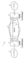
図1は第1の実施形態に係るパケット無中断伝送システム1のシステム構成例を示す説明図である。図1の例では、両端に描かれたユーザネットワーク2および3(ユーザNW2および3)の間で送受信されるパケットを中央に描かれた広域ネットワーク4(広域NW4)を介して接続するシステム構成になっており、ユーザネットワーク2および3と広域ネットワーク4の境界には2つのネットワーク間の中継を行う伝送装置(本実施形態に係るパケット無中断切替装置5および6)がそれぞれ設置されている。
Embodiments of a packet non-disruptive transmission system, a packet non-disruptive switching device, and a packet non-disruptive switching method according to the present invention will be described below with reference to the drawings.
(First embodiment)
[Outline of packet uninterrupted transmission system]
FIG. 1 is an explanatory diagram showing a system configuration example of a packet
図1において、例えばパケット無中断切替装置5はユーザNW2から送信されるパケットを複製して経路A、B,CおよびDの複数の経路に分けて広域NW4側に転送し、逆に広域NW4の複数経路から受信する複数のパケットの1つを選択してユーザNW2側に転送するようになっている。
In FIG. 1, for example, the packet
ここで、パケット無中断切替装置5および6の基本動作について図2のフローチャートを用いて説明する。図2のフローチャートは、例えばパケット無中断切替装置5の場合、ユーザNW2から受信したパケットを広域NW4に送信する送信側処理と、広域NW4から受信したパケットをユーザNW2に送信する受信側処理とで構成される。
Here, the basic operation of the
送信側処理では、例えば図1のユーザNW2からパケットを受信すると(ステップS1)、受信したパケットを経路の数だけ複製し(ステップS2)、複製したパケットに順序などを示す識別子をそれぞれ付与し(ステップS3)、複数のパケットをそれぞれ異なる経路に分けて広域NW4に送信する(ステップS4)。尚、パケットを複製してから識別子を付加しても構わないし、パケットに識別子を付加してから複製しても構わない。 In the transmission side processing, for example, when a packet is received from the user NW2 in FIG. 1 (step S1), the received packet is duplicated by the number of routes (step S2), and an identifier indicating the order or the like is assigned to each duplicated packet ( In step S3), the plurality of packets are divided into different routes and transmitted to the wide area NW4 (step S4). Note that the identifier may be added after the packet is duplicated, or the identifier may be duplicated after the identifier is added to the packet.
一方、受信側処理では、例えばパケット無中断切替装置6から広域NW4を介して複数の異なる経路で送られてくるパケットを受信すると(ステップS5)、受信したパケットの識別子を確認して複数経路の中で一番早く受信した正常のパケット(早着パケット)を選択し(ステップS6)、選択したパケットから識別子を消去してユーザNW2側に転送する(ステップS7)。
On the other hand, in the receiving process, for example, when a packet sent from a packet
このようにパケット無中断切替装置5および6は、複製した複数のパケットを複数の経路で伝送するので一部の経路に障害が発生した場合でもパケット損失を発生せず、且つ経路切替を行う場合でも遅延揺らぎの少ない信頼性の高いネットワークを実現することができる。尚、本実施形態では、パケット無中断切替装置5および6の名称を、その機能が分かり易いように「パケット無中断切替装置」と称したが、一般的なパケット伝送装置,パケット転送装置,パケット中継装置などと称しても構わない。また、本実施形態で特に明記せずに「パケット」と称しているものは、ユーザ情報に宛先などのヘッダ情報を付加した一塊の伝送情報単位を示すもので、OSIレイヤのレイヤ3などで使われるパケットや、レイヤ2などで使われるフレームなどを含むものとする。従って、本実施形態に係るパケット無中断伝送システムおよびパケット無中断切替装置並びにパケット無中断切替方法は、デジタルデータを所定の伝送情報単位に区切って伝送するシステムや装置であれば同様に適用することができる。
In this way, the packet
ところが、上記のように複製したパケットを複数系統の伝送路に分けて送信する場合、各系統の伝送路の長さが異なるため、複数系統の伝送路を流れる同じ識別子を有するパケットの到着時間には伝送路長差に相当する遅延が生じる。ここで、例えば図1の経路A,B,CおよびDの中で伝送路長の長い経路を長系と称し、逆に伝送路長の短い経路を短系と称する場合、短系の経路を流れるパケットの到着時間は長系の経路を流れる同じ複製されたパケットの到着時間より早いので、短系から長系に切り替える時に遅延時間が生じる。この従来方式のパケットトラフィックの様子を図3(a)に示す。図3(a)は、短系の経路から受信するパケット列と、長系の経路から受信する複製された同じパケット列と、短系または長系から選択されたパケットが下流のネットワークや装置に出力される選択系のパケット列との時間的な位置関係がわかるように描いた説明図である。尚、図3(a)の例では、切替を行う前後の12個のパケット列を示し、四角で囲まれた1から12までの数字はそれぞれ1つのパケットを示しており、同じ番号のパケットは同じ複製されたパケットを示している。以降、これらの12個のパケットをパケット(1),パケット(2),・・・,パケット(12)のように表記する。
However, when the packet copied as described above is divided into a plurality of transmission paths and transmitted, the lengths of the transmission paths of each system are different. Causes a delay corresponding to the transmission path length difference. Here, for example, in the case of the routes A, B, C and D in FIG. 1, a route having a long transmission path length is referred to as a long system, and conversely, a route having a short transmission path length is referred to as a short system. Since the arrival time of the flowing packet is earlier than the arrival time of the same duplicated packet that flows through the long path, a delay time occurs when switching from the short system to the long system. The state of packet traffic of this conventional method is shown in FIG. FIG. 3A shows a packet sequence received from a short route, a duplicate packet sequence received from a long route, and a packet selected from the short route or long route to a downstream network or device. It is explanatory drawing drawn so that the temporal positional relationship with the packet string of the selection system output might be understood. In the example of FIG. 3 (a), 12 packet sequences before and after switching are shown. The
図3(a)において、短系のパケット(1)の到着時間と長系のパケット(1)の到着時間とはL秒の伝送路遅延がある。例えば短系のパケット(5)を選択後に短系から長系への計画切替(運用者による切替操作)が実行された場合、長系のパケット(6)が到着するまで選択系ではパケット(5)を転送してからパケット(6)を転送するまで待たされることになり、伝送路遅延分の揺らぎが生じる。 In FIG. 3A, the arrival time of the short packet (1) and the arrival time of the long packet (1) have a transmission path delay of L seconds. For example, when the planned switching from the short system to the long system (switching operation by the operator) is executed after selecting the short system packet (5), the packet (5 in the selected system until the long system packet (6) arrives. ) Is transferred until the packet (6) is transferred, and fluctuations in the transmission path delay occur.
これに対して、本実施形態に係るパケット無中断伝送システムおよびパケット無中断切替装置並びにパケット無中断切替方法は、後で説明するように、図3(a)のような伝送路遅延による揺らぎの発生を少なくすることができるようになっている。
[パケット無中断切替装置5および6の構成]
次に、パケット無中断切替装置5および6の構成例について図4を用いて詳しく説明する。図4は、パケット無中断切替装置5および6に対応する1つの構成例を示すパケット無中断切替装置100のブロック図である。図4において、パケット無中断切替装置100は送信機能部101と受信機能部102とを有している。
On the other hand, the packet non-disruptive transmission system, the packet non-disruptive switching device, and the packet non-disruptive switching method according to the present embodiment, as will be described later, the fluctuation due to the transmission path delay as shown in FIG. Occurrence can be reduced.
[Configuration of packet
Next, a configuration example of the packet
図4に示す送信機能部101は、ユーザNWから受信したデータを広域NWへ送信するためのブロックで、受信部111と、コピー部112と、識別子付与部113aおよび113bと、送信部114aおよび114bとで構成される。尚、図4では分かり易いように2つの経路を有する場合の構成例を描いてあるので、コピー部112以降のブロックはそれぞれ2系統(広域NW4の経路Aに対応するa系統と、広域NW4の経路Bに対応するb系統)の同じブロックを有するが、2系統より多い数の経路に分けて送信する場合は経路数だけコピー部112以降のブロックを設ければよい。また、以降の説明において、特定のブロックを指す場合を除いて、例えば識別子付与部113aおよび識別子付与部113bは識別子付与部113のように系統名(a,b)を省略して表記するものとし、例えば送信部114aおよび送信部114bは送信部114と表記する。また、以降の図面に出現する同様のブロックについても特に明記しない限り同様に系統名(a,b)を省略して表記する。
The
受信部111は、ユーザNWからのパケットを受信する。尚、先に説明したように、パケットの種類は何でもよく、例えばイーサネット(登録商標)のIPパケットであっても構わないし、MACフレームなどのフレームであっても構わない。或いは、MPLS(Multi−Protocol Label Switching)に対応したパケットであっても構わない。
The receiving
コピー部112は、受信部で受信したユーザNWからのパケットと同一の情報を持つ複数のパケットを複製する。
The
識別子付与部113は、複製された複数のパケットにそれぞれ順序識別子(および経路識別子)を書き込む。ここで、順序識別子は送信順序を示す識別子で、0,1,2,3・・・の整数値が送信する度に順番に1ずつ増加され、その数値が書き込まれる(尚、1,2,3・・・の自然数でも構わない)。また、経路識別子は送信する伝送経路を示す識別子で伝送経路の1系,2系・・・などに対応する1〜nの値が書き込まれるが、経路識別子はなくても構わない。
The identifier assigning unit 113 writes an order identifier (and a route identifier) in each of the duplicated packets. Here, the order identifier is an identifier indicating the transmission order. Each time an integer value of 0, 1, 2, 3... Is transmitted, it is incremented by 1 and the numerical value is written (note that 1, 2, 2, etc.). It may be a natural number of 3 ...). In addition, the path identifier is an identifier indicating the transmission path to be transmitted, and
送信部114は、識別子付与部113で順序識別子などが付与された複数のパケットを広域NW側にそれぞれ異なる経路に送信する。例えば、同じ順序識別子が付与された同じ情報を含む2つの複製パケットの中の1つのパケットが送信部114aから経路Aに送信され、もう1つのパケットが送信部114bから経路Bに送信される。
The transmission unit 114 transmits a plurality of packets, to which the order identifiers and the like are assigned by the identifier assignment unit 113, to different routes on the wide area NW side. For example, one of the two duplicate packets including the same information to which the same order identifier is assigned is transmitted from the
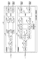
次に、受信機能部102について説明する。図4において、受信機能部102は、広域NWから受信した信号をユーザNWへ送信するためのブロックで、受信部121(受信部121aおよび121b)と、遅延判定部122(遅延判定部122aおよび122b)と、遅延調整用メモリ123(遅延調整用メモリ123aおよび123b)と、メモリ124(メモリ124aおよび124b)と、選択部125(選択部125aおよび125b)と、カウンタ部126と、送信部127と、遅延制御部128とで構成される。ここで、点線枠で囲んだ遅延調整ブロック151および遅延制御部128で構成されるブロックが本発明に係るパケット無中断伝送システムおよびパケット無中断切替装置並びにパケット無中断切替方法の特徴となる部分である。特に、図4の場合は、遅延調整ブロック151は、遅延判定部122aおよび122bの遅延判定ブロック152と、遅延調整用メモリ123aおよび123bの遅延調整用メモリブロック153とで構成される。
Next, the reception function unit 102 will be described. In FIG. 4, a reception function unit 102 is a block for transmitting a signal received from a wide area NW to a user NW, and includes a reception unit 121 (
受信部121aおよび121bは、それぞれ対応する広域NWの経路Aおよび経路Bから送られてくるパケットを受信する。
Receiving
遅延判定部122は、各経路から受信した同一の順序識別子を持つパケットの遅延差(到着時間の差)を判定し、遅延制御部128に遅延差情報を出力する。その後、当該受信パケットは受信した経路に応じて遅延調整用メモリ123に保持された後、遅延制御部128からの命令に応じて所定の遅延が挿入されてメモリ124に蓄積される。つまり、所定時間(0(遅延無し)を含む)だけ遅れてメモリ123から読み出されてメモリ124に蓄積される。
The delay determination unit 122 determines the delay difference (arrival time difference) of packets having the same order identifier received from each path, and outputs delay difference information to the
遅延調整用メモリ123は、先に書き込まれたパケットから先に読み出すFIFOメモリで構成される。尚、遅延判定部122が出力するパケットを順番に蓄積し、遅延制御部128の読み出し指令に応じて先に書き込まれたパケットから順番に読み出す。
The delay adjustment memory 123 is composed of a FIFO memory that reads first from a previously written packet. The packets output from the delay determination unit 122 are accumulated in order, and are read out in order from the previously written packet in response to a read command from the
メモリ124もFIFOメモリで構成され、遅延調整用メモリ123から読み出されるパケットを順番に蓄積し、選択部125によって先に書き込まれたパケットから順番に読み出される。 The memory 124 is also composed of a FIFO memory, and the packets read from the delay adjustment memory 123 are accumulated in order, and the selection unit 125 sequentially reads the packets written in advance.
選択部125は、メモリ124から読み出したパケットの順序識別子を参照し、複数経路から受信した同一情報を持つパケットの中の先着パケットを選択して送信部127に出力する。尚、選択されなかった同一情報を持つパケットは廃棄される。つまり、早着のパケットがあった場合には、後着のパケットは廃棄される。
The selection unit 125 refers to the sequence identifier of the packet read from the memory 124, selects the first-arrival packet among the packets having the same information received from a plurality of paths, and outputs it to the
送信部127は、選択部125から出力されるパケットから順序識別子を消去した後、下流のネットワークや装置に転送する。
The
遅延制御部128は、運用者による経路切替要求(計画切替要求)が与えられた場合に、遅延判定部122と、遅延調整用メモリ123とを制御して、パケットトラフィックの経路の切替を行う。例えば図4の場合では、経路Aから経路Bへの切り替え要求を行ったり、逆に経路Bから経路Aへの切り替え要求を行う。或いは、一旦切り替えられたパケットトラフィックを元に戻す計画切替解除要求が与えられた場合には、逆の動作を行う。
When a route switching request (plan switching request) is given by an operator, the
尚、図4では一般的なパケット転送装置としてパケット無中断切替装置100を構成する場合のブロック図を用いて説明したが、本発明はこれに限定されるものではない。
[SONET/SDHまたはOTNへの適用例]
例えば、Packet over SONET/SDH(SONET(Synchronous Optical NETwork:同期光伝送網)/SDH(Synchronous Digital Hierarchy:同期デジタル・ハイアラーキ))に対応する伝送装置やOTN(Optical Transport Network:光伝送網)に対応する伝送装置などにも適用することができる。例えば、図5は、図4で説明したパケット無中断切替装置100をPacket over SONET/SDHに対応させた場合のパケット無中断切替装置200の構成を示すブロック図である。
In FIG. 4, the block diagram in the case where the packet
[Application example to SONET / SDH or OTN]
For example, a transmission device corresponding to Packet over SONET / SDH (SONET (Synchronous Optical Network) / SDH (Synchronous Digital Hierarchy)) or an OTN (Optical Network) The present invention can also be applied to a transmission device that performs such processing. For example, FIG. 5 is a block diagram illustrating a configuration of the packet
ここで、図5と図4の違いについて説明する。図5はSDHに対応するために、送信機能部201には、GFP(Generic Framing Procedure)マッピング部211と、VC(Virtual Container)マッピング部212aおよび212bと、VCマッピングしたフレームを多重化する多重部213とが配置されている。また、受信機能部202には、受信部121で広域NWから受信したVCフレームを分離する分離部221と、VCデマッピング部222aおよび222bと、GFPデマッピング部223とが配置されている。上記以外のブロックは図4と同様に構成される。尚、分かり易いように、図4と同符号のものは図4で説明した機能と同じ機能を有するが、その扱うデータが異なり、GFPフレームであったりVCフレームであったりする。例えば、送信機能部201の受信部111でユーザNWから受信したパケットはGFPマッピング部211でGFPフレームにマッピングされる。そして、コピー部112はGFPフレームを複製して識別子付与部113に出力する。さらに、順序識別子や経路識別子が付与されたGFPフレームはVCマッピング部212でVCフレームにマッピングされ、多重部213で多重化された後、送信部114からそれぞれの経路を介して広域NWに送信される。
Here, the difference between FIG. 5 and FIG. 4 will be described. 5 corresponds to SDH, the
一方、受信機能部202の受信部121は広域NWの各経路から多重化されたフレームを受信し、分離部221で多重化されたフレームを分離する。そして、VCデマッピング部222は、GFPフレームにデマッピングし、デマッピングされたGFPフレームは遅延調整ブロック151の遅延判定部122で同じフレームの遅延時間の判定を行って遅延制御部128に出力すると共に、当該フレームを遅延調整用メモリ123に一時的に記憶する。遅延制御部128は図4で説明したように、計画切替要求/解除要求に応じて、遅延判定部122から入力する遅延時間の判定結果を用いて遅延調整用メモリ123に一時的に記憶されているGFPフレームを適宜読み出しでメモリ124に蓄積する。そして、選択部125は、カウンタ部126のカウント値とメモリ124に蓄積されているGFPフレームの順序識別子を参照して早着のフレームを選択してGFPデマッピング部223に出力する。GFPデマッピング部223は、選択部125から出力されるGFPフレームをデマッピングしたパケットを送信部127に出力し、送信部127からユーザNWに転送される。
On the other hand, the reception unit 121 of the
このように、Packet over SONET/SDHに対応するパケット無中断切替装置200の場合でも図4で詳しく説明したパケット無中断切替装置100と同様に処理することができる。
As described above, even in the case of the packet
次に、Packet over SONET/SDHに対応するその他のパケット無中断切替装置250の構成例を図6に示す。尚、図6において、図4および図5と同符号のものは同じ機能のブロックを示す。図5と図6の違いは、送信機能部251において、VCマッピング部212の位置が異なる。図5では、VCマッピング部212aおよび212bは、識別子付与部113で識別子が付与された後に配置されていたが、図6ではVCマッピング部212はGFPマッピング部211の直後に配置されている。これにより、図5の場合に比べてVCマッピング部212のブロック数を減らすことができるので回路規模が小さくなり、コスト削減を図ることができる。
Next, FIG. 6 shows a configuration example of another packet
同様に、受信機能部252において、VCデマッピング部222の位置が異なる。図4では、VCデマッピング部222aおよび222bは、分離部221の直後に配置されていたが、図6ではVCデマッピング部222はGFPデマッピング部223の直前に配置されている。これにより、図5の場合に比べてVCデマッピング部222のブロック数を減らすことができるので回路規模が小さくなり、コスト削減を図ることができる。
Similarly, in the
次に、OTNに対応するパケット無中断切替装置260の構成例を図7に示す。尚、図7において、図4および図5と同符号のものは同じ機能のブロックを示す。図5と図7の違いは、OTNに対応するために、送信機能部261において、VCマッピング部212および多重部213の代わりにOTNマッピング部214が配置されていることである。図7において、識別子付与部113で順序識別子や経路識別子が付与されたGFPフレームはOTNマッピング部214でOTNフレームにマッピングされ、送信部114からそれぞれの経路を介して広域NWに送信される。
Next, a configuration example of the packet
一方、受信機能部262においては、受信部121で広域NWの各経路から受信されたOTNフレームは、OTNデマッピング部224でGFPフレームにデマッピングし、デマッピングされたGFPフレームは遅延調整ブロック151の遅延判定部122で同じフレームの遅延時間の判定を行って遅延制御部128に出力すると共に、当該フレームを遅延調整用メモリ123に一時的に記憶する。遅延制御部128は図4で説明したように、計画切替要求/解除要求に応じて、遅延判定部122から入力する遅延時間の判定結果を用いて遅延調整用メモリ123に一時的に記憶されているGFPフレームを適宜読み出しでメモリ124に蓄積する。そして、選択部125は、カウンタ部126のカウント値とメモリ124に蓄積されているGFPフレームの順序識別子を参照して早着のフレームを選択してGFPデマッピング部223に出力する。GFPデマッピング部223は、選択部125から出力されるGFPフレームをデマッピングしたパケットを送信部127に出力し、送信部127からユーザNWに転送される。
On the other hand, in the
このように、OTNに対応するパケット無中断切替装置260の場合でも図4で詳しく説明したパケット無中断切替装置100と同様に処理することができる。
As described above, even in the case of the packet
次に、OTNに対応するその他のパケット無中断切替装置270の構成例を図8に示す。尚、図8において、図4および図7と同符号のものは同じ機能のブロックを示す。図7と図8の違いは、送信機能部271において、OTNマッピング部214の位置が異なる。図7では、OTNマッピング部214は、識別子付与部113で識別子が付与された後に配置されていたが、図8ではOTNマッピング部214は図7のGFPマッピング部211の代わりに同じ位置に配置されている。これにより、図7の場合に比べてOTNマッピング部214のブロック数を減らすことができるので回路規模が小さくなり、コスト削減を図ることができる。
Next, FIG. 8 shows a configuration example of another packet
同様に、受信機能部272において、OTNデマッピング部224の位置が異なる。図7では、OTNデマッピング部224aおよび224bは、受信部121の直後に配置されていたが、図8ではOTNデマッピング部224はGFPデマッピング部223の代わりに同じ位置に配置されている。これにより、図7の場合に比べてOTNデマッピング部224のブロック数を減らすことができるので回路規模が小さくなり、コスト削減を図ることができる。
Similarly, in the
以上、図5,図6,図7および図8を用いて説明したように、本発明に係るパケット無中断伝送システムおよびパケット無中断切替装置並びにパケット無中断切替方法は、SONET/SDHまたはOTNに対しても適用することができる。
[遅延制御部128および遅延調整ブロック151の動作について]
次に、図4において、遅延調整ブロック151を構成する遅延判定ブロック152と、遅延調整用メモリ123と、遅延制御部128の動作について詳しく説明する。
As described above with reference to FIGS. 5, 6, 7, and 8, the packet non-disruptive transmission system, the packet non-disruptive switching device, and the packet non-disruptive switching method according to the present invention are applied to SONET / SDH or OTN. It can also be applied to.
[Operations of
Next, operations of the
遅延調整用メモリ123aと123bは、遅延制御部128と連動しており、運用者がOpS(オペレーションシステム)や対向装置から出力する計画切替要求/解除要求に応じて遅延調整用メモリ123aと123bを用いて一時的に保持されているパケットの遅延量を調整する。
The
遅延制御部128は、OpSからの計画切替要求/解除要求を受けて、遅延判定部122が出力する各経路から受信した同一の順序識別子を持つパケットの遅延差情報を参照して、メモリ124へパケットを出力する遅延量の制御を行なう。
The
図9は、図4のa系統の遅延調整用メモリ123aを用いた処理例を示すフローチャートである。尚、b系統の遅延調整用メモリ123bについても同様のフローチャートとなる。
FIG. 9 is a flowchart showing a processing example using the
(ステップS11)受信パケットが遅延調整用メモリ123aに書き込まれる。
(Step S11) The received packet is written into the
(ステップS12)伝送路aから伝送路bへの計画切替モードであるか否かを判別する。そして、計画切替モードである場合にはS13に進み、それ以外の場合にはS16に進む。 (Step S12) It is determined whether or not it is a plan switching mode from the transmission path a to the transmission path b. And when it is plan switching mode, it progresses to S13, and when that is not right, it progresses to S16.
(ステップS13)遅延調整用メモリ123a側のパケットと遅延調整用メモリ123b側のパケットとの遅延差τ(a−b)を判別する。そして、遅延差τ(a−b)>0を満たす場合はS14に進み、満たさない場合はS15に進む。尚、遅延差τ(a−b)<0の場合は、切替要求先のパケットが元々早着であるので、そのままメモリ124aにパケットを転送する。
(Step S13) The delay difference τ (ab) between the packet on the
(ステップS14)遅延調整用メモリ123a側へのパケットの方が遅延調整用メモリ123bへ受信される同一情報を持つパケットよりも早く受信されるので、遅延調整用メモリ123aが受信したパケットに所定の遅延量τ1を挿入する。尚、遅延量τ1は、時間に比例してリニアに増加させるか、パケット受信毎にΔτ1ずつ段階的に増加させるよう制御される。この遅延量τ1の挿入方法については、図10、図11を用いて後で詳しく説明する。
尚、遅延量τ1の挿入例は図10、図11を用いて後で詳しく説明する。
(Step S14) Since the packet to the
An example of inserting the delay amount τ1 will be described in detail later with reference to FIGS.
(ステップS15)遅延量τ1の遅延が挿入されたパケット(τ1の時間だけ遅れて読み出したパケット)をメモリ124aに転送する。
(Step S15) The packet in which the delay of τ1 is inserted (the packet read with a delay of τ1) is transferred to the
(ステップS16)伝送路aから伝送路bへの計画切替解除モードであるか否かを判別する。そして、計画切替解除モードである場合にはS17に進み、それ以外の場合にはS15に進む。ここで、計画切替モードでなく、計画切替解除モードでもない場合には、S15に進んで、そのままパケットをメモリ124aに転送する。
(Step S16) It is determined whether or not it is a plan switching cancellation mode from the transmission path a to the transmission path b. If it is the plan switching cancellation mode, the process proceeds to S17, and otherwise, the process proceeds to S15. Here, if it is neither the plan switching mode nor the plan switching cancellation mode, the process proceeds to S15, and the packet is transferred to the
(ステップS17)遅延調整用メモリ123a側へのパケットの方が遅延調整用メモリ123bへ受信される同一情報を持つパケットよりも早く受信されるので、遅延調整用メモリ123aが受信したパケットに所定の遅延量τ2を挿入する。尚、遅延量τ2は、時間に比例してリニアに減少させるか、パケット受信毎にΔτ2ずつ段階的に減少させるよう制御される。この遅延量τ2の挿入方法については、図12、図13を用いて後で詳しく説明する。
[遅延量τ1の挿入方法]
次に、遅延量τ1の挿入方法について説明する。先ず、遅延量τ1の挿入方法の一例を図10のグラフを用いて説明する。尚、図10において、横軸は時間軸(t)、縦軸は遅延時間の差(遅延差:τ)を示す。図10に示した方法は、時間tの経過に比例して所定の遅延量τ1を増やしていく方法である。図10において、OpSからの切替要求発生時点を0としてtz1秒後にa系とb系との遅延差τ(a−b)よりも大きい遅延量τ1が挿入されるように、時間に比例して遅延量を徐々に増やしていく。尚、a系とb系の遅延差τ(a−b)は遅延判定部122によって測定される。
(Step S17) Since the packet to the
[Method of inserting delay amount τ1]
Next, a method for inserting the delay amount τ1 will be described. First, an example of a method for inserting the delay amount τ1 will be described with reference to the graph of FIG. In FIG. 10, the horizontal axis represents the time axis (t), and the vertical axis represents the delay time difference (delay difference: τ). The method shown in FIG. 10 is a method of increasing the predetermined delay amount τ1 in proportion to the passage of time t. In FIG. 10, the switching request occurrence time from OpS is set to 0, and a delay amount τ1 larger than the delay difference τ (ab) between the a system and the b system is inserted after tz1 seconds in proportion to time. Gradually increase the amount of delay. The delay difference τ (ab) between the a system and the b system is measured by the delay determination unit 122.
ここで、遅延量τ1が遅延量τ(a−b)に近い場合、僅かな処理遅延や遅延揺らぎなどによってパケットの到達順序が入れ変わるので、切り替え処理が正常に行なえない場合がある。このため、目標となる遅延量τ1はτ(a−b)よりも余裕を持って大きくなるまでの時間(tz2)まで徐々に遅延を増加する処理を継続した後、切替元のパケットの遅延量τ1を一定に保つように遅延制御部128は処理する。
Here, when the delay amount τ1 is close to the delay amount τ (ab), the packet arrival order is changed due to a slight processing delay, delay fluctuation, or the like, so that the switching process may not be performed normally. For this reason, after continuing the process of gradually increasing the delay until the target delay amount τ1 becomes larger than τ (ab) with a margin (tz2), the delay amount of the switching source packet The
次に、遅延量τ1の挿入方法のその他の例を図11のグラフを用いて説明する。尚、図11のグラフは図10と同様に、横軸は時間軸(t)、縦軸は遅延時間の差(遅延差:τ)を示す。図10に示した方法は、時間tに比例してリニアに遅延量τ1になるまで増やしていく方法であったが、図11は遅延量τ(a−b)以上に到達するまで、切替元のパケット到達毎に遅延量Δτ1を段階的に増やしていく方法である。そして、図10の場合と同様に、τ1>τ(a−b)となるまで、遅延量Δτ1を段階的に増やして行き、遅延量τ(a−b)より十分に余裕を持つ遅延量τ1になった以後の切替元のパケットについてはその遅延量τ1に保つ。尚、パケットの到達頻度が少ない場合は、τ1に達していない場合にタイムアウトするように制御して、タイムアウトした場合に遅延量をτ1に強制的に設定するようにしても構わない。 Next, another example of the method of inserting the delay amount τ1 will be described using the graph of FIG. 11, the horizontal axis indicates the time axis (t) and the vertical axis indicates the difference in delay time (delay difference: τ), as in FIG. The method shown in FIG. 10 is a method of increasing linearly in proportion to the time t until the delay amount τ1 is reached, but FIG. 11 shows the switching source until the delay amount τ (ab) or more is reached. In this method, the delay amount Δτ1 is increased step by step every time a packet arrives. Similarly to the case of FIG. 10, the delay amount Δτ1 is increased stepwise until τ1> τ (ab), and the delay amount τ1 having a sufficient margin from the delay amount τ (ab). For the switching source packet after becoming, the delay amount τ1 is maintained. If the arrival frequency of the packet is low, it may be controlled to time out when it does not reach τ1, and the delay amount may be forcibly set to τ1 when timed out.
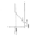
ここで、計画切替要求が与えられて、遅延量を段階的に増やしていく場合の具体的なパケットトラフィックの様子について図3(b)を用いて説明する。尚、図3(b)は、先に説明した従来方式のパケットトラフィックの様子を示す図3(a)と同様に、短系の経路から受信するパケット列と、長系の経路から受信する複製された同じパケット列と、短系または長系から選択されたパケットが下流のネットワークや装置に出力される選択系のパケット列との時間的な位置関係がわかるように描いた説明図である。また、図3(a)と同様に、切替を行う前後の12個のパケット列を示し、四角で囲まれた1から12までの数字で示してあり、以降の説明では、これらの12個のパケットをパケット(1),パケット(2),・・・,パケット(12)のように表記する。
Here, a specific state of packet traffic when the plan switching request is given and the delay amount is increased stepwise will be described with reference to FIG. FIG. 3B shows a packet sequence received from the short path and a copy received from the long path, as in FIG. 3A showing the state of the conventional packet traffic described above. It is explanatory drawing drawn so that the temporal positional relationship might be understood with the same packet sequence and the packet sequence of the selection system from which the packet selected from the short system or the long system was output to a downstream network or apparatus. Similarly to FIG. 3A, 12 packet sequences before and after switching are shown by
図3(b)において、短系のパケット(1)の到着時間と長系のパケット(1)の到着時間とはL秒の伝送路遅延がある。例えば短系のパケット(5)を選択後に短系から長系への計画切替要求が与えられた場合、図3(a)では長系のパケット(6)が到着するまで選択系ではパケットが出力されない状態になったが、本実施形態では長系のパケットが到着するタイミングよりも遅くなるまで短系のパケットが到着する毎に少しずつ段階的に遅らせるように制御する。例えば、計画切替要求が与えられた最初の短系のパケット(6)は所定の遅延量Δτだけ遅らせて選択系に出力する。ここで、遅延量Δτは、揺らぎの影響が問題とならない程度の遅延量とする。次の2つ目の短系のパケット(7)は、遅延量(Δτ×2)だけ遅らせて選択系に出力する。この時点でも、遅延されたパケット(7)は切替先の長系のパケット(7)の到着タイミングよりも早いので、さらに次の3つ目の短系のパケット(8)を遅延量(Δτ×3)だけ遅らせて選択系に出力する。同様に、短系のパケット(9)は遅延量(Δτ×4)だけ遅らせて選択系に出力する。そして、次の5つ目の短系のパケット(10)を遅延量(Δτ×5)だけ遅らせると、長系のパケット(10)の到着タイミングよりも遅くなるので、ここで初めて長系のパケット(10)に切り替えて選択系に出力する。ここで、Δτは図11のΔτ1に対応する。 In FIG. 3B, the arrival time of the short packet (1) and the arrival time of the long packet (1) have a transmission path delay of L seconds. For example, when a request for switching a plan from the short system to the long system is given after selecting the short system packet (5), the packet is output in the selected system until the long system packet (6) arrives in FIG. However, in this embodiment, the control is performed so as to gradually delay each time a short packet arrives until it becomes later than the arrival timing of the long packet. For example, the first short packet (6) to which the plan switching request is given is delayed by a predetermined delay amount Δτ and output to the selection system. Here, the delay amount Δτ is a delay amount that does not cause a problem of fluctuation. The next second short packet (7) is delayed by the delay amount (Δτ × 2) and output to the selection system. Even at this time point, the delayed packet (7) is earlier than the arrival timing of the switching-destination long packet (7), so the next third short packet (8) is further transferred to the delay amount (Δτ × 3) Delay the output and output to the selection system. Similarly, the short packet (9) is delayed by the delay amount (Δτ × 4) and output to the selection system. Then, if the fifth short packet (10) is delayed by the delay amount (Δτ × 5), it will be later than the arrival timing of the long packet (10). Switch to (10) and output to the selection system. Here, Δτ corresponds to Δτ1 in FIG.
このように、本実施形態に係るパケット無中断伝送システムおよびパケット無中断切替装置並びにパケット無中断切替方法では、短系から長系への計画切替要求が与えられた時点以降の短系のパケットを所定の遅延量だけ待たせて選択系に出力し、待たせた短系のパケットが選択系に出力されるタイミングが長系の同じパケットの到着タイミングよりも遅くなった時点で長系のパケットに切替を行うよう制御し、短系のパケットと長系のパケットの遅延差を段階的に徐々に縮めるように制御するので遅延揺らぎの発生を少なくすることができる。
[遅延量τ2の挿入方法]
次に、遅延量τ2の挿入方法の一例を図12のグラフを用いて説明する。尚、図12において、横軸は時間軸(t)、縦軸は遅延時間の差(遅延差:τ)を示す。図12に示した方法は、時間tの経過に比例して所定の遅延量τ2が0になるまで減らしていく方法である。図12において、OpSからの切替解除要求発生時点を0としてtz3秒後にa系とb系との遅延差τ(a−b)が0になるように、遅延量τ2を時間に比例して徐々に減らしていく。
As described above, in the packet non-disruptive transmission system, the packet non-disruptive switching device, and the packet non-disruptive switching method according to the present embodiment, the short-system packet after the time point when the request for switching the plan from the short system to the long system is given. Wait for a predetermined delay amount and output to the selection system, and when the timing of outputting the waiting short system packet to the selection system is later than the arrival timing of the same long system packet, it becomes a long system packet Since the switching is controlled so that the delay difference between the short packet and the long packet is gradually reduced step by step, the occurrence of delay fluctuation can be reduced.
[Method of inserting delay amount τ2]
Next, an example of a method for inserting the delay amount τ2 will be described using the graph of FIG. In FIG. 12, the horizontal axis represents the time axis (t), and the vertical axis represents the delay time difference (delay difference: τ). The method shown in FIG. 12 is a method of decreasing until the predetermined delay amount τ2 becomes 0 in proportion to the passage of time t. In FIG. 12, the delay amount τ2 is gradually increased in proportion to the time so that the delay difference τ (ab) between the a system and the b system becomes 0 after
次に、遅延量τ2の挿入方法のその他の例を図13のグラフを用いて説明する。尚、図13のグラフは図12と同様に、横軸は時間軸(t)、縦軸は遅延時間の差(遅延差:τ)を示す。図12に示した方法は、時間tに比例してリニアに遅延量τ2を減らしていく方法であったが、図13は遅延量τ(a−b)が0になるまで、パケット到達毎に遅延量Δτ2ずつ段階的に減らしていく方法である。尚、パケットの到達頻度が少なく遅延量が0に達していない場合は、タイムアウトするように制御して、タイムアウトした場合に遅延量を強制的に0に設定するようにしても構わない。 Next, another example of the method of inserting the delay amount τ2 will be described using the graph of FIG. 13, the horizontal axis indicates the time axis (t), and the vertical axis indicates the delay time difference (delay difference: τ). The method shown in FIG. 12 is a method of decreasing the delay amount τ2 linearly in proportion to the time t. However, FIG. 13 shows that every time the packet arrives until the delay amount τ (ab) becomes zero. In this method, the delay amount Δτ2 is decreased step by step. Note that when the arrival frequency of the packet is low and the delay amount has not reached 0, control may be made to time out, and the delay amount may be forcibly set to 0 when the timeout occurs.
ここで、図13は、図3(b)で説明した段階的に遅延量Δτを増やしていく方法の逆の動作を行うことに相当する。例えば、図3(b)において、Δτが図13のΔτ2に対応し、遅延量τ2が例えば遅延量(Δτ×5)に対応する。そして、長系から短系に戻すための計画切替解除要求が与えられた場合に、短系のパケットが到着する毎に遅延量τ2からΔτ2だけ段階的に減少させていき、最終的に遅延量τ2が0になった時点で計画切替解除モードが終了する。 Here, FIG. 13 corresponds to performing the reverse operation of the method of increasing the delay amount Δτ stepwise described with reference to FIG. For example, in FIG. 3B, Δτ corresponds to Δτ2 in FIG. 13, and the delay amount τ2 corresponds to, for example, the delay amount (Δτ × 5). Then, when a plan switch release request for returning from the long system to the short system is given, every time a short system packet arrives, the delay amount τ2 is gradually decreased by Δτ2, and finally the delay amount The plan switching release mode ends when τ2 becomes zero.
このように、本実施形態に係るパケット無中断伝送システムおよびパケット無中断切替装置並びにパケット無中断切替方法では、短系から長系への計画切替解除要求が与えられた時点以降の短系のパケットの遅延量を徐々に減少させて選択系に出力するので、計画切替解除モードでの遅延揺らぎの発生を少なくすることができる。 As described above, in the packet non-disruptive transmission system, the packet non-disruptive switching device, and the packet non-disruptive switching method according to the present embodiment, the short packet after the point when the request for canceling the plan switching from the short system to the long system is given. Since the delay amount is gradually reduced and output to the selection system, the occurrence of delay fluctuation in the plan switching cancellation mode can be reduced.
以上、本実施形態に係るパケット無中断伝送システムおよびパケット無中断切替装置並びにパケット無中断切替方法は、OpS又は対向装置からの計画切替要求/解除要求を受けた場合に、短系と長系のパケット間の遅延差を徐々に縮めることで、転送先のネットワークや装置に対する遅延揺らぎを最小限に抑えることができる。 As described above, the packet non-disruptive transmission system, the packet non-disruptive switching device, and the packet non-disruptive switching method according to the present embodiment can be used for the short system and the long system when receiving the plan switching request / cancellation request from the OpS or the opposite device. By gradually reducing the delay difference between the packets, it is possible to minimize delay fluctuations with respect to the transfer destination network or device.
[第1の実施形態の変形例1]
次に、上記で説明した実施形態の変形例1について、図14を用いて説明する。図11および図13では、切替解除時の遅延量調整を時間tに比例して減少させるか段階的減少させるように制御したが、図14に示すように、一気に遅延量を0にするようにしても構わない。尚、図14において、図9と同じ符号のステップは同じ処理を行う。図9と異なるのは、ステップS12において、計画切替モードではない場合は、全てS15に進むので、計画切替解除モードである場合は、一気に遅延量が0に制御される。
[
Next,
[第1の実施形態の変形例2]
次に、上記で説明した実施形態の変形例2について説明する。上記で説明した実施形態では、a系とb系の切り替えを遅延量の調整だけで行なうようにしたが、遅延の挿入によってa系とb系の切り替えを行なった後、選択部125において、選択する系を固定する方法で実現しても構わない。例えば、a系からb系に切り替える場合、選択部125は切替後はb系のパケットトラフィックを固定的に選択するように処理する。これにより、選択部125で早着のパケットを判別する処理を常に行う必要がなくなるので、処理負担が少なくなる。
[
Next, a second modification of the embodiment described above will be described. In the embodiment described above, switching between the a-system and the b-system is performed only by adjusting the delay amount. However, after switching between the a-system and the b-system by inserting a delay, the selection unit 125 performs selection. You may implement | achieve by the method of fixing the system to perform. For example, when switching from the a-system to the b-system, the selection unit 125 performs processing to select the b-system packet traffic after the switching. This eliminates the need for the selection unit 125 to always perform the process of discriminating early arrival packets, thereby reducing the processing load.
このように、本実施形態に係るパケット無中断伝送システムおよびパケット無中断切替装置並びにパケット無中断切替方法は、伝送路が短く遅延時間が短い短系の経路のパケットトラフィックから伝送路が長く遅延時間が長い長系の経路のパケットトラフィックに切り替える場合に、切替時のパケット間隔が急激に変化することがなくなり、短系と長系の遅延時間差による揺らぎの発生を抑えることができる。 As described above, the packet non-interruptible transmission system, the packet non-interruptible switching device, and the packet non-interruptible switching method according to the present embodiment are configured so that the transmission path has a long delay time from the packet traffic of a short route with a short transmission path and a short delay time. When switching to long-path packet traffic with a long path, the packet interval at the time of switching does not change abruptly, and fluctuations due to the difference in delay time between the short and long systems can be suppressed.
特に、短系から長系へのパケットトラフィックの切替時において、パケット間隔が所定時間ずつ徐々に増加するので、短系と長系の遅延時間差が大きい場合でも揺らぎの発生を抑えることができる。 In particular, when switching the packet traffic from the short system to the long system, the packet interval gradually increases by a predetermined time, so that the occurrence of fluctuation can be suppressed even when the delay time difference between the short system and the long system is large.
また、短系から長系へ切り替えたパケットトラフィックを再び長系から短系へ戻す場合でも、パケット間隔が所定時間ずつ徐々に減少するので、短系と長系の遅延時間差が大きい場合でも揺らぎの発生を抑えることができる。
(第2の実施形態)
次に、本発明に係るパケット無中断伝送システムおよびパケット無中断切替装置並びにパケット無中断切替方法の第2の実施形態について説明する。尚、第2の実施形態に係るパケット無中断伝送システムは、第1の実施形態の図1で説明したパケット無中断伝送システム1と同じである。同様に、図1のユーザネットワーク2および3と広域ネットワーク4の境界に配置された2つのネットワーク間の中継を行う伝送装置(パケット無中断切替装置5および6)が第2の実施形態に係るパケット無中断切替装置300に相当する。図15に、パケット無中断切替装置300のブロック図を示す。
Even when packet traffic switched from the short system to the long system is returned from the long system to the short system again, the packet interval gradually decreases by a predetermined time, so even if the delay time difference between the short system and the long system is large, fluctuations Occurrence can be suppressed.
(Second Embodiment)
Next, a second embodiment of the packet non-disruptive transmission system, the packet non-disruptive switching device, and the packet non-disruptive switching method according to the present invention will be described. The packet uninterrupted transmission system according to the second embodiment is the same as the packet
尚、本実施形態に係るパケット無中断切替装置300は第1の実施形態とは別の方法で短系と長系のパケットの遅延差を徐々に縮め、短系と長系のパケットの遅延が逆転した時点で切替を完了する計画切替を実現するようになっている。第1の実施形態では、図4で説明したように、遅延調整用メモリ123を用いて受信パケットの遅延量を調整するようにしたが、第2の実施形態では、図15に示すように、遅延調整用メモリ123を用いるのではなく選択部125で処理する方法によって、受信パケットの遅延量を制御するようになっている。これにより、第1の実施形態と同様に、遅延揺らぎの無い計画切替を実現することができる。
Note that the packet
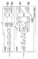
図15において、パケット無中断切替装置300は、送信機能部301と、受信機能部302とで構成される。送信機能部301はユーザNWから受信したパケットを広域NWへ送信し、受信機能部302は広域NWから受信した信号をユーザNWへ送信する。
In FIG. 15, the packet
図15に示す送信機能部301は、受信部111と、コピー部112と、識別子付与部113aおよび113bと、送信部114aおよび114bとで構成される。尚、送信機能部301の構成は、図4で説明した送信機能部101と同じ構成であり、図4と同一符号のブロックと同様の動作を行う。
The
次に、受信機能部302について説明する。図15において、受信機能部302は、広域NWから受信した信号をユーザNWへ送信するためのブロックで、受信部121(受信部121aおよび121b)と、遅延判定部122(遅延判定部122aおよび122b)と、メモリ124(メモリ124aおよび124b)と、選択部325(選択部325aおよび325b)と、カウンタ部126と、送信部127と、遅延制御部328とで構成される。ここで、点線枠で囲んだ遅延判定ブロック152および遅延制御部328に加えて遅延調整選択ブロック354で構成される部分が本発明に係るパケット無中断伝送システムおよびパケット無中断切替装置並びにパケット無中断切替方法の特徴となる部分である。特に、図15の場合は、遅延調整選択ブロック354は、選択部325とカウンタ部126とで構成される。図4と異なるのは、遅延調整用メモリ123(遅延調整用メモリ123aおよび123b)が無いことと、遅延制御部328が遅延調整選択ブロック354の選択部325を制御することである。
Next, the
受信機能部302において、受信部121aおよび121bは、それぞれ対応する広域NWの経路Aおよび経路Bから送られてくるパケットを受信する。そして、遅延判定部122は、各経路から受信した同一の順序識別子を持つパケットの遅延差(到着時間の差)を判定し、遅延制御部128に遅延差情報を出力する。その後、当該受信パケットは受信した経路に応じてメモリ124に蓄積される。
In the
選択部325は、メモリ124から読み出したパケットの順序識別子を参照し、複数経路から受信した同一情報を持つパケットの中の先着パケットを選択して送信部127に出力する。尚、選択されなかった同一情報を持つパケットは廃棄される。つまり、早着のパケットがあった場合には、後着のパケットは廃棄される。特に、本実施形態では、選択部325は遅延制御部328と連動しており、OpSから与えられる計画切替要求/解除要求に応じてパケットに与える遅延量(本実施形態ではパケットを選択するまでの待機時間に相当)を調整する。このようにして遅延量が調整されて選択されたパケットは、送信部127で順序識別子が消去された後、下流のネットワークや装置に転送される。このように、遅延制御部328は、計画切替要求/解除要求が与えられた場合に、遅延判定部122と、選択部325とを制御して、パケットトラフィックの経路の切替を行う。或いは、一旦切り替えられたパケットトラフィックを元に戻す計画切替解除要求が与えられた場合には、逆の動作を行う。
The selection unit 325 refers to the sequence identifier of the packet read from the memory 124, selects the first-arrival packet among the packets having the same information received from a plurality of paths, and outputs it to the
ここで、図15では一般的なパケット転送装置としてパケット無中断切替装置300を構成する場合のブロック図を用いて説明したが、第1の実施形態の図5から図8で説明したようにSONET/SDHやOTNなどへも適用することができ、本発明はこれらに限定されるものではない。
Here, FIG. 15 is described using a block diagram in the case where the packet
次に、第2の実施形態に係るパケット無中断切替装置300の遅延制御部328に計画切替要求/解除要求が与えられた場合の遅延量の制御方法について図16のフローチャートを用いて説明する。尚、本実施形態では、独立した2つの経路の場合を示しており、それぞれa系およびb系と称している。従って、経路数がn(nは自然数)の場合は、例えば1系〜n系までのn個について同様の処理を行なうものとする。以下、図16のフローチャートに従って説明する。
Next, a delay amount control method when a plan switching request / release request is given to the
(ステップS31)カウンタ部126のカウント値(CS)を0にリセットする。
(Step S31) The count value (CS) of the
(ステップS32)a系のメモリ124aの受信パケットの有無を確認する。そして、a系のメモリ124aに受信パケットがある場合はS33に進み、受信パケットがない場合はS40に進む。
(Step S32) The presence or absence of a received packet in the
(ステップS33)メモリ124aの受信パケットを読み出す。
(Step S33) The received packet of the
(ステップS34)読み出した受信パケットの順序識別子(Ca)とカウンタ部のカウント値(CS)とを比較する。そして、CS=Ca、CS>Ca、CS>Caの3つの条件に分けて処理し、CS=Caの場合はS35に進み、CS>Caの場合はS39に進み、CS>Caの場合はS40に進む。 (Step S34) The sequence identifier (Ca) of the read received packet is compared with the count value (CS) of the counter unit. The processing is divided into three conditions of CS = Ca, CS> Ca, and CS> Ca. If CS = Ca, the process proceeds to S35. If CS> Ca, the process proceeds to S39. If CS> Ca, the process proceeds to S40. Proceed to
(ステップS35)a系からb系への計画切替モードであるか否かを判別する。そして、Yesの場合はS36に進み、Noの場合はS37に進む。 (Step S35) It is determined whether or not it is a plan switching mode from the a system to the b system. If Yes, the process proceeds to S36, and if No, the process proceeds to S37.
(ステップS36)待機時間(τ1)が満了したか否かを判別する。尚、待機時間は、遅延制御部328がタイマー機能を有し、予め設定した待機時間(τ1)が満了した場合はS37に進み、待機時間(τ1)が満了していない場合はS40に進む。尚、待機時間(τ1)は第1の実施形態で説明した図10,図11の方法と同様である。
(Step S36) It is determined whether or not the waiting time (τ1) has expired. The
ここで、ステップS35とステップS36の処理が本実施形態の特徴となる遅延制御処理を行う部分である。 Here, the process of step S35 and step S36 is a part which performs the delay control process which becomes the characteristic of this embodiment.
(ステップS37)メモリ124aの受信パケットを送信部127に出力すると共に、当該受信パケットをメモリ124aから消去する。
(Step S37) The received packet in the
(ステップS38)カウンタのカウント値(CS)を1つカウントアップし(CS=CS+1)、S40に進む。 (Step S38) The count value (CS) of the counter is incremented by 1 (CS = CS + 1), and the process proceeds to S40.
(ステップS39)メモリ124aの受信パケットは別系において既に到着しているパケットであると認識できるので、当該受信パケットをメモリ124aから消去する。
(Step S39) Since the received packet in the
(ステップS40)b系のメモリ124bの受信パケットの有無を確認する。そして、b系のメモリ124bに受信パケットがある場合はS41に進み、受信パケットがない場合はS32に戻って次のパケットの受信を待つ。
(Step S40) The presence or absence of a received packet in the b-
(ステップS41)メモリ124bの受信パケットを読み出す。
(Step S41) The received packet of the
(ステップS42)読み出した受信パケットの順序識別子(Cb)とカウンタ部のカウント値(CS)とを比較する。そして、CS=Cb、CS>Cb、CS>Cbの3つの条件に分けて処理し、CS=Cbの場合はS43に進み、CS>Cbの場合はS47に進み、CS>Cbの場合はS48に進む。 (Step S42) The sequence identifier (Cb) of the read received packet is compared with the count value (CS) of the counter unit. The processing is divided into three conditions of CS = Cb, CS> Cb, and CS> Cb. If CS = Cb, the process proceeds to S43. If CS> Cb, the process proceeds to S47. If CS> Cb, the process proceeds to S48. Proceed to
(ステップS43)b系からa系への計画切替モードであるか否かを判別する。そして、Yesの場合はS44に進み、Noの場合はS32に戻って次のパケットの受信を待つ。 (Step S43) It is determined whether or not it is a plan switching mode from the b system to the a system. If Yes, the process proceeds to S44. If No, the process returns to S32 to wait for reception of the next packet.
(ステップS44)ステップS36と同様に、待機時間(τ1)が満了したか否かを判別する。待機時間(τ1)が満了した場合はS45に進み、待機時間(τ1)が満了していない場合はS32に戻って次のパケットの受信を待つ。 (Step S44) Similarly to step S36, it is determined whether or not the standby time (τ1) has expired. When the waiting time (τ1) has expired, the process proceeds to S45, and when the waiting time (τ1) has not expired, the process returns to S32 and waits for reception of the next packet.
ここで、ステップS35とステップS36の処理と同様に、ステップS43とステップS44の処理は本実施形態の特徴となる遅延制御処理を行う部分である。 Here, similarly to the processing of step S35 and step S36, the processing of step S43 and step S44 is a part for performing the delay control processing which is a feature of this embodiment.
(ステップS45)メモリ124bの受信パケットを送信部127に出力すると共に、当該受信パケットをメモリ124bから消去する。
(Step S45) The received packet in the
(ステップS46)カウンタのカウント値(CS)を1つカウントアップし(CS=CS+1)、S32に戻って次のパケットの受信を待つ。 (Step S46) The count value (CS) of the counter is incremented by 1 (CS = CS + 1), and the process returns to S32 to wait for reception of the next packet.
(ステップS47)メモリ124bの受信パケットは別系において既に到着しているパケットであると認識できるので、当該受信パケットをメモリ124bから消去し、S32に戻って次のパケットの受信を待つ。
(Step S47) Since the received packet in the
(ステップS48)CS<Caであるか否かを判別する。そして、CS<Caの場合はS49に進み、CS>Caの場合はS32に戻って次のパケットの受信を待つ。 (Step S48) It is determined whether CS <Ca. If CS <Ca, the process proceeds to S49. If CS> Ca, the process returns to S32 to wait for reception of the next packet.
(ステップS49)カウンタのカウント値(CS)を1つカウントアップし(CS=CS+1)、S32に戻って次のパケットの受信を待つ。 (Step S49) The count value (CS) of the counter is incremented by 1 (CS = CS + 1), and the process returns to S32 to wait for reception of the next packet.
このように、本実施形態に係るパケット無中断切替装置300では、メモリ124aまたはメモリ124bに取り込まれた受信パケットは、計画切替モードの場合は所定の待機時間だけ遅延させて送信部127に出力されるので、揺らぎの発生を抑えることができる。
As described above, in the packet
特に、第1の実施形態の図10および図11で説明したように、遅延制御部328が、2つの経路の遅延差を徐々に縮めるように選択部325がメモリ124から受信パケットを読み出すタイミングを制御することで、遅延揺らぎを最小限に抑えることができる。
In particular, as described with reference to FIGS. 10 and 11 of the first embodiment, the timing at which the selection unit 325 reads the received packet from the memory 124 so that the
尚、図16のフローチャートでは、計画切替要求時のみの処理を示したが、第1の実施形態と同様に、計画切替解除時の処理も行うことができる。この場合は遅延量を徐々に0にする制御を行えばよい。 In the flowchart of FIG. 16, the processing only when the plan switching is requested is shown, but the processing when the plan switching is canceled can be performed as in the first embodiment. In this case, the control may be performed so that the delay amount is gradually reduced to zero.
さらに、第2の実施形態では、選択部325における選択処理においてパケットの遅延調整を行なうので、第1の実施形態で用いた遅延調整用メモリ123が不要となる。この結果、パケット無中断切替装置300の回路規模を小さくでき、コスト削減を図ることができる。
Furthermore, in the second embodiment, since the packet delay adjustment is performed in the selection process in the selection unit 325, the delay adjustment memory 123 used in the first embodiment is not necessary. As a result, the circuit scale of the packet
尚、図16では、a系の処理後にb系の処理を行なうフローチャートを示したが、全ての経路の処理を並列に行って、下流に流すパケットの判断を行なうようにしても構わない。 Note that FIG. 16 shows a flowchart for performing the b-system processing after the a-system processing, but it is also possible to perform the processing of all routes in parallel and determine the packets to be sent downstream.
また、本実施形態に係るパケット無中断伝送システムおよびパケット無中断切替装置並びにパケット伝送方法における転送パケットの処理手順は、本実施形態に限定されるものではない。 Further, the processing procedure of the transfer packet in the packet non-interruptible transmission system, the packet non-interruptible switching device, and the packet transmission method according to the present embodiment is not limited to the present embodiment.
[第2の実施形態の変形例1]
次に、上記で説明した実施形態の変形例1について説明する。上記で説明した実施形態では、a系とb系の切り替えを遅延量の調整だけで行なうようにしたが、遅延の挿入によってa系とb系の切り替えを行なった後、選択部325において、選択する系を固定する方法で実現しても構わない。例えば、a系からb系に切り替える場合、選択部325は切替後はb系のパケットトラフィックを固定的に選択するように処理する。これにより、選択部325で早着のパケットを判別する処理を常に行う必要がなくなるので、処理負担が少なくなる。
[
Next,
以上、本実施形態に係るパケット無中断伝送システムおよびパケット無中断切替装置並びにパケット無中断切替方法は、OpS又は対向装置からの計画切替要求を受けた場合に、短系と長系のパケット間の遅延差を徐々に縮めることで、転送先のネットワークや装置に対する遅延揺らぎを最小限に抑えることができる。 As described above, the packet non-interruptible transmission system, the packet non-interruptible switching device, and the packet non-interruptible switching method according to the present embodiment, when receiving a plan switching request from the OpS or the opposite device, By gradually reducing the delay difference, it is possible to minimize delay fluctuations with respect to the transfer destination network or device.
尚、本発明に係るパケット無中断伝送システムおよびパケット無中断切替装置並びにパケット無中断切替方法について各実施形態で例を挙げて説明してきたが、その精神またはその主要な特徴から逸脱することなく他の多様な形で実施することができる。そのため、上述した実施形態はあらゆる点で単なる例示に過ぎず、限定的に解釈してはならない。本発明は、特許請求の範囲によって示されるものであって、本発明は明細書本文にはなんら拘束されない。さらに、特許請求の範囲の均等範囲に属する変形や変更は、全て本発明の範囲内である。 The packet uninterrupted transmission system, the packet uninterruptible switching device, and the packet uninterruptible switching method according to the present invention have been described by way of example in the respective embodiments. However, without departing from the spirit or the main features thereof Can be implemented in various ways. Therefore, the above-described embodiment is merely an example in all respects and should not be interpreted in a limited manner. The present invention is shown by the scope of claims, and the present invention is not limited to the text of the specification. Further, all modifications and changes belonging to the equivalent scope of the claims are within the scope of the present invention.
1・・・パケット無中断伝送システム
2,3・・・ユーザNW
4・・・広域NW
5,6,100,200,250,260,270,300・・・パケット無中断切替装置
101,201,251,261,271,301・・・送信機能部
102,202,252,262,272,302・・・受信機能部
111・・・受信部
112・・・コピー部
113a,113b・・・識別子付与部
114a,114b,・・・送信部
121a,121b・・・受信部
122a,122b・・・遅延判定部
123a,123b・・・遅延調整用メモリ
124a,124b・・・メモリ
125a,125b,325a,325b・・・選択部
126・・・カウンタ部
127・・・送信部
128,328・・・遅延制御部
151・・・遅延調整ブロック
152・・・遅延判定ブロック
153・・・遅延調整用メモリブロック
211・・・GFPマッピング部
212,212a,212b・・・VCマッピング部
213・・・多重部
214,214a,214b・・・OTNマッピング部
221・・・分離部
222,222a,222b・・・VCデマッピング部
223・・・GFPデマッピング部
224,224a,224b・・・OTNデマッピング部
354・・・遅延調整選択ブロック
1 ... Packet
4 ... Wide area network
5, 6, 100, 200, 250, 260, 270, 300...
Claims (15)
前記受信側で下流に転送するパケットを第1の経路の受信パケットから第2の経路の受信パケットに切り替える指示を与える切替指示手段と、
前記切替指示手段から指示された時点以降に前記第1の経路から受信するパケットと同一のパケットが前記第2の経路から受信されるまでの遅延時間が予め設定した閾値より長い場合に、前記遅延時間が前記閾値以下になるまで切替元の第1の経路のパケットを徐々に遅延させるパケット遅延手段と
を設けたことを特徴とするパケット無中断伝送システム。 A transmission side that duplicates a packet with an order identifier added and transmits it via a plurality of routes; and a reception side that selects an early arrival packet from among packets with the same identifier received from a plurality of routes and forwards it downstream In a packet uninterrupted transmission system having
Switching instruction means for giving an instruction to switch a packet transferred downstream on the receiving side from a received packet of the first path to a received packet of the second path;
When the delay time until the same packet received from the first path after the time point instructed by the switching instruction means is received from the second path is longer than a preset threshold, the delay A packet non-interruptible transmission system, comprising: a packet delay unit that gradually delays the packet of the first path of the switching source until the time becomes equal to or less than the threshold value.
前記パケット遅延手段は、
前記切替指示手段から指示された時点以降に前記第1の経路から受信するパケットと同一のパケットが前記第2の経路から受信するまでの遅延時間を判定する遅延判定手段と、
受信パケットを受信順に一時的に保持して読み出し指令に応じて受信順に受信パケットを読み出す遅延調整メモリと、
前記遅延判定手段が判定した遅延時間が0より大きい場合に、前記遅延時間が0以下になるまで切替元の第1の経路の受信パケットを前記遅延調整メモリから読み出す際の遅延量を時間に比例して増加させる遅延制御手段と
で構成されることを特徴とするパケット無中断伝送システム。 The packet uninterrupted transmission system according to claim 1,
The packet delay means includes
A delay determination unit that determines a delay time until the same packet received from the first route after the time point instructed by the switching instruction unit is received from the second route;
A delay adjustment memory that temporarily holds the received packets in the order of reception and reads out the received packets in the order of reception according to the read command;
When the delay time determined by the delay determination means is greater than 0, the delay amount when reading the received packet of the first path of the switching source from the delay adjustment memory is proportional to time until the delay time becomes 0 or less. And a non-interruptible transmission system characterized by comprising delay control means for increasing the number of delays.
前記パケット遅延手段は、
前記切替指示手段から指示された時点以降に前記第1の経路から受信するパケットと同一のパケットが前記第2の経路から受信するまでの遅延時間を判定する遅延判定手段と、
受信パケットを受信順に一時的に保持して読み出し指令に応じて受信順に受信パケットを読み出す遅延調整メモリと、
前記遅延判定手段が判定した遅延時間が0より大きい場合に、前記遅延時間が0以下になるまで切替元の第1の経路の受信パケットを前記遅延調整メモリから読み出す際の遅延量を所定時間ずつ段階的に増加させる遅延制御手段と
で構成されることを特徴とするパケット無中断伝送システム。 The packet uninterrupted transmission system according to claim 1,
The packet delay means includes
A delay determination unit that determines a delay time until the same packet received from the first route after the time point instructed by the switching instruction unit is received from the second route;
A delay adjustment memory that temporarily holds the received packets in the order of reception and reads out the received packets in the order of reception according to the read command;
When the delay time determined by the delay determination means is greater than 0, the amount of delay when reading the received packet of the switching source first path from the delay adjustment memory until the delay time becomes 0 or less by a predetermined time. A packet non-interruptible transmission system comprising: delay control means for increasing in stages.
前記切替指示手段により切り替えられた切替先の第2の経路の受信パケットから切替元の第1の経路の受信パケットに戻す指示を与える切替解除指示手段をさらに設け、
前記遅延制御手段は、前記切替解除指示手段から解除指示が与えられた時点以降に前記切替元の第1の経路の受信パケットを前記遅延調整メモリから読み出す際の遅延量を時間に反比例して減少させる
ことを特徴とするパケット無中断伝送システム。 The packet uninterrupted transmission system according to claim 2 or 3,
A switch release instruction means for giving an instruction to return from the received packet of the second route of the switching destination switched by the switching instruction means to the received packet of the first route of the switching source,
The delay control unit decreases the delay amount when reading the received packet of the first route of the switching source from the delay adjustment memory after the time when the cancellation instruction is given from the switching cancellation instruction unit in inverse proportion to time. A non-interruptible transmission system for packets.
前記受信機能部は、
下流に転送するパケットを第1の経路の受信パケットから第2の経路の受信パケットに切り替える指示を与える切替指示手段と、
前記切替指示手段から指示された時点以降に前記第1の経路から受信するパケットと同一のパケットが前記第2の経路から受信されるまでの遅延時間が予め設定した閾値より長い場合に、前記遅延時間が前記閾値以下になるまで切替元の第1の経路のパケットを徐々に遅延させるパケット遅延手段と
で構成されることを特徴とするパケット無中断切替装置。 A transmission function unit that duplicates a packet to which an order identifier is added and transmits it via a plurality of routes, and a reception function that selects an early arrival packet from among packets to which the same identifier is received from a plurality of routes and forwards it downstream A packet non-disruptive switching device having a
The reception function unit includes:
Switching instruction means for giving an instruction to switch a packet to be transferred downstream from a received packet on the first path to a received packet on the second path;
When the delay time until the same packet received from the first path after the time point instructed by the switching instruction means is received from the second path is longer than a preset threshold, the delay A packet non-interruptible switching device comprising: packet delay means for gradually delaying the packet of the switching source first path until the time becomes equal to or less than the threshold value.
前記パケット遅延手段は、
前記切替指示手段から指示された時点以降に前記第1の経路から受信するパケットと同一のパケットが前記第2の経路から受信するまでの遅延時間を判定する遅延判定手段と、
受信パケットを受信順に一時的に保持して読み出し指令に応じて受信順に受信パケットを読み出す遅延調整メモリと、
前記遅延判定手段が判定した遅延時間が0より大きい場合に、前記遅延時間が0以下になるまで切替元の第1の経路の受信パケットを前記遅延調整メモリから読み出す際の遅延量を時間に比例して増加させる遅延制御手段と
で構成されることを特徴とするパケット無中断切替装置。 The packet non-disruptive switching device according to claim 6,
The packet delay means includes
A delay determination unit that determines a delay time until the same packet received from the first route after the time point instructed by the switching instruction unit is received from the second route;
A delay adjustment memory that temporarily holds the received packets in the order of reception and reads out the received packets in the order of reception according to the read command;
When the delay time determined by the delay determination means is greater than 0, the delay amount when reading the received packet of the first path of the switching source from the delay adjustment memory is proportional to time until the delay time becomes 0 or less. And a non-interruptible packet switching device characterized by comprising delay control means for increasing the number of packets.
前記パケット遅延手段は、
前記切替指示手段から指示された時点以降に前記第1の経路から受信するパケットと同一のパケットが前記第2の経路から受信するまでの遅延時間を判定する遅延判定手段と、
受信パケットを受信順に一時的に保持して読み出し指令に応じて受信順に受信パケットを読み出す遅延調整メモリと、
前記遅延判定手段が判定した遅延時間が0より大きい場合に、前記遅延時間が0以下になるまで切替元の第1の経路の受信パケットを前記遅延調整メモリから読み出す際の遅延量を所定時間ずつ段階的に増加させる遅延制御手段と
で構成されることを特徴とするパケット無中断切替装置。 The packet non-disruptive switching device according to claim 6,
The packet delay means includes
A delay determination unit that determines a delay time until the same packet received from the first route after the time point instructed by the switching instruction unit is received from the second route;
A delay adjustment memory that temporarily holds the received packets in the order of reception and reads out the received packets in the order of reception according to the read command;
When the delay time determined by the delay determination means is greater than 0, the amount of delay when reading the received packet of the switching source first path from the delay adjustment memory until the delay time becomes 0 or less by a predetermined time. A packet non-interruptible switching device comprising: delay control means for increasing in stages.
前記切替指示手段により切り替えられた切替先の第2の経路の受信パケットから切替元の第1の経路の受信パケットに戻す指示を与える切替解除指示手段をさらに設け、
前記遅延制御手段は、前記切替解除指示手段から解除指示が与えられた時点以降に前記切替元の第1の経路の受信パケットを前記遅延調整メモリから読み出す際の遅延量を時間に反比例して減少させる
ことを特徴とするパケット無中断切替装置。 The packet non-disruptive switching device according to claim 7 or 8,
A switch release instruction means for giving an instruction to return from the received packet of the second route of the switching destination switched by the switching instruction means to the received packet of the first route of the switching source,
The delay control unit decreases the delay amount when reading the received packet of the first route of the switching source from the delay adjustment memory after the time when the cancellation instruction is given from the switching cancellation instruction unit in inverse proportion to time. A non-interruptible packet switching device characterized by
前記切替指示手段により切り替えられた切替先の第2の経路の受信パケットから切替元の第1の経路の受信パケットに戻す指示を与える切替解除指示手段をさらに設け、
前記遅延制御手段は、前記切替解除指示手段から解除指示が与えられた時点以降に前記切替元の第1の経路の受信パケットを前記遅延調整メモリから読み出す毎に与えられる遅延量を所定時間ずつ段階的に減少させる
ことを特徴とするパケット無中断切替装置。 The packet non-disruptive switching device according to claim 7 or 8,
A switch release instruction means for giving an instruction to return from the received packet of the second route of the switching destination switched by the switching instruction means to the received packet of the first route of the switching source,
The delay control means increments the delay amount given every time a received packet of the first route of the switching source is read from the delay adjustment memory after a time point when the cancellation instruction is given from the switching cancellation instruction means by a predetermined time. Packet non-disruptive switching device, characterized in that the number is reduced.
前記受信側で下流に転送するパケットを第1の経路の受信パケットから第2の経路の受信パケットに切り替える指示を与える切替指示手順と、
前記切替指示手順から指示された時点以降に前記第1の経路から受信するパケットと同一のパケットが前記第2の経路から受信されるまでの遅延時間が予め設定した閾値より長い場合に、前記遅延時間が前記閾値以下になるまで切替元の第1の経路のパケットを徐々に遅延させるパケット遅延手順と
を設けたことを特徴とするパケット無中断切替方法。 A transmission side that duplicates a packet with an order identifier added and transmits it via a plurality of routes; and a reception side that selects an early arrival packet from among packets with the same identifier received from a plurality of routes and forwards it downstream In a packet uninterruptible switching method used in a packet uninterrupted transmission system having
A switching instruction procedure for giving an instruction to switch a packet to be transferred downstream on the receiving side from a received packet on the first path to a received packet on the second path;
When the delay time until the same packet received from the first path after the time point instructed from the switching instruction procedure is received from the second path is longer than a preset threshold, the delay A packet delay procedure for gradually delaying the packet of the first path of the switching source until the time becomes equal to or less than the threshold value.
前記パケット遅延手順は、
前記切替指示手順から指示された時点以降に前記第1の経路から受信するパケットと同一のパケットが前記第2の経路から受信するまでの遅延時間を判定する遅延判定手順と、
受信パケットを受信順に一時的に保持して読み出し指令に応じて受信順に受信パケットを読み出す遅延調整メモリと、
前記遅延判定手順が判定した遅延時間が0より大きい場合に、前記遅延時間が0以下になるまで切替元の第1の経路の受信パケットを前記遅延調整メモリから読み出す際の遅延量を時間に比例して増加させる遅延制御手順と
で構成されることを特徴とするパケット無中断切替方法。 The packet non-disruptive switching method according to claim 11,
The packet delay procedure is:
A delay determination procedure for determining a delay time until a packet identical to a packet received from the first path after the time point instructed from the switching instruction procedure is received from the second path;
A delay adjustment memory that temporarily holds the received packets in the order of reception and reads out the received packets in the order of reception according to the read command;
When the delay time determined by the delay determination procedure is larger than 0, the delay amount when the received packet of the switching source first path is read from the delay adjustment memory until the delay time becomes 0 or less is proportional to the time. And a non-interruptible packet switching method, characterized by comprising:
前記パケット遅延手順は、
前記切替指示手順から指示された時点以降に前記第1の経路から受信するパケットと同一のパケットが前記第2の経路から受信するまでの遅延時間を判定する遅延判定手順と、
受信パケットを受信順に一時的に保持して読み出し指令に応じて受信順に受信パケットを読み出す遅延調整メモリと、
前記遅延判定手順が判定した遅延時間が0より大きい場合に、前記遅延時間が0以下になるまで切替元の第1の経路の受信パケットを前記遅延調整メモリから読み出す際の遅延量を所定時間ずつ段階的に増加させる遅延制御手順と
で構成されることを特徴とするパケット無中断切替方法。 The packet non-disruptive switching method according to claim 11,
The packet delay procedure is:
A delay determination procedure for determining a delay time until a packet identical to a packet received from the first path after the time point instructed from the switching instruction procedure is received from the second path;
A delay adjustment memory that temporarily holds the received packets in the order of reception and reads out the received packets in the order of reception according to the read command;
When the delay time determined by the delay determination procedure is larger than 0, the delay amount when reading the received packet of the first route of the switching source from the delay adjustment memory until the delay time becomes 0 or less is set for each predetermined time. A packet non-interruptible switching method, characterized by comprising a delay control procedure that increases in stages.
前記切替指示手順により切り替えられた切替先の第2の経路の受信パケットから切替元の第1の経路の受信パケットに戻す指示を与える切替解除指示手順をさらに設け、
前記遅延制御手順は、前記切替解除指示手順から解除指示が与えられた時点以降に前記切替元の第1の経路の受信パケットを前記遅延調整メモリから読み出す際の遅延量を時間に反比例して減少させる
ことを特徴とするパケット無中断切替方法。 The packet non-disruptive switching method according to claim 12 or 13,
A switching cancellation instruction procedure for giving an instruction to return from the received packet of the second route of the switching destination switched by the switching instruction procedure to the received packet of the first route of the switching source;
In the delay control procedure, the delay amount when the received packet of the first route of the switching source is read from the delay adjustment memory after the time when the release instruction is given from the switch release instruction procedure is decreased in inverse proportion to the time. A packet non-disruptive switching method characterized by
前記切替指示手順により切り替えられた切替先の第2の経路の受信パケットから切替元の第1の経路の受信パケットに戻す指示を与える切替解除指示手順をさらに設け、
前記遅延制御手順は、前記切替解除指示手順から解除指示が与えられた時点以降に前記切替元の第1の経路の受信パケットを前記遅延調整メモリから読み出す毎に与えられる遅延量を所定時間ずつ段階的に減少させる
ことを特徴とするパケット無中断切替方法。 The packet non-disruptive switching method according to claim 12 or 13,
A switching cancellation instruction procedure for giving an instruction to return from the received packet of the second route of the switching destination switched by the switching instruction procedure to the received packet of the first route of the switching source;
In the delay control procedure, a delay amount given every time a received packet of the first route of the switching source is read from the delay adjustment memory after a time point when the release instruction is given from the switch release instruction procedure is incremented by a predetermined time. Packet non-disruptive switching method, characterized in that the number is reduced.
Priority Applications (1)
| Application Number | Priority Date | Filing Date | Title |
|---|---|---|---|
| JP2009130191A JP2010278845A (en) | 2009-05-29 | 2009-05-29 | Packet non-interrupt transmission system, packet non-interrupt switching device, and packet non-interrupt switching method |
Applications Claiming Priority (1)
| Application Number | Priority Date | Filing Date | Title |
|---|---|---|---|
| JP2009130191A JP2010278845A (en) | 2009-05-29 | 2009-05-29 | Packet non-interrupt transmission system, packet non-interrupt switching device, and packet non-interrupt switching method |
Publications (2)
| Publication Number | Publication Date |
|---|---|
| JP2010278845A true JP2010278845A (en) | 2010-12-09 |
| JP2010278845A5 JP2010278845A5 (en) | 2011-12-22 |
Family
ID=43425377
Family Applications (1)
| Application Number | Title | Priority Date | Filing Date |
|---|---|---|---|
| JP2009130191A Pending JP2010278845A (en) | 2009-05-29 | 2009-05-29 | Packet non-interrupt transmission system, packet non-interrupt switching device, and packet non-interrupt switching method |
Country Status (1)
| Country | Link |
|---|---|
| JP (1) | JP2010278845A (en) |
Cited By (5)
| Publication number | Priority date | Publication date | Assignee | Title |
|---|---|---|---|---|
| JP2012205136A (en) * | 2011-03-25 | 2012-10-22 | Nec Corp | Transmission device, transmission system, route selection method and route selection program |
| JP2013005210A (en) * | 2011-06-16 | 2013-01-07 | Fujitsu Telecom Networks Ltd | Packet transmission system, packet transmission device, and uninterruptible switching method |
| WO2013015114A1 (en) * | 2011-07-25 | 2013-01-31 | ソニー株式会社 | Communication device, communication method, and communication system |
| JP2015519801A (en) * | 2012-04-18 | 2015-07-09 | アクメ パケット インコーポレイテッドAcme Packet, Inc. | Redundancy for real-time communication |
| JP2020535712A (en) * | 2017-09-25 | 2020-12-03 | 華為技術有限公司Huawei Technologies Co.,Ltd. | Methods and network devices for forwarding packets |
Citations (4)
| Publication number | Priority date | Publication date | Assignee | Title |
|---|---|---|---|---|
| JPH0738610A (en) * | 1993-07-23 | 1995-02-07 | Nippon Telegr & Teleph Corp <Ntt> | Packet transmission system |
| WO2006011225A1 (en) * | 2004-07-30 | 2006-02-02 | Mitsubishi Denki Kabushiki Kaisha | Communication system, packet switch apparatus, and edge node apparatus |
| JP2007228282A (en) * | 2006-02-23 | 2007-09-06 | Ntt Communications Kk | Transmitting device, transmitting method, and program |
| JP2008022337A (en) * | 2006-07-13 | 2008-01-31 | Nec Corp | Method and system for packet transmission |
-
2009
- 2009-05-29 JP JP2009130191A patent/JP2010278845A/en active Pending
Patent Citations (4)
| Publication number | Priority date | Publication date | Assignee | Title |
|---|---|---|---|---|
| JPH0738610A (en) * | 1993-07-23 | 1995-02-07 | Nippon Telegr & Teleph Corp <Ntt> | Packet transmission system |
| WO2006011225A1 (en) * | 2004-07-30 | 2006-02-02 | Mitsubishi Denki Kabushiki Kaisha | Communication system, packet switch apparatus, and edge node apparatus |
| JP2007228282A (en) * | 2006-02-23 | 2007-09-06 | Ntt Communications Kk | Transmitting device, transmitting method, and program |
| JP2008022337A (en) * | 2006-07-13 | 2008-01-31 | Nec Corp | Method and system for packet transmission |
Non-Patent Citations (2)
| Title |
|---|
| CSNG200000787003; 金山 之治 他: '高品質映像伝送に向けたATM無中断伝送装置の開発' 映像情報メディア学会技術報告 第22巻,第72号, 19981218, p.13〜19 * |
| JPN6013043450; 金山 之治 他: '高品質映像伝送に向けたATM無中断伝送装置の開発' 映像情報メディア学会技術報告 第22巻,第72号, 19981218, p.13〜19 * |
Cited By (11)
| Publication number | Priority date | Publication date | Assignee | Title |
|---|---|---|---|---|
| JP2012205136A (en) * | 2011-03-25 | 2012-10-22 | Nec Corp | Transmission device, transmission system, route selection method and route selection program |
| JP2013005210A (en) * | 2011-06-16 | 2013-01-07 | Fujitsu Telecom Networks Ltd | Packet transmission system, packet transmission device, and uninterruptible switching method |
| WO2013015114A1 (en) * | 2011-07-25 | 2013-01-31 | ソニー株式会社 | Communication device, communication method, and communication system |
| JP2013026947A (en) * | 2011-07-25 | 2013-02-04 | Sony Corp | Communication device, communication method and communication system |
| US9912587B2 (en) | 2011-07-25 | 2018-03-06 | Sony Corporation | Communication apparatus, communication method, and communication system |
| JP2015519801A (en) * | 2012-04-18 | 2015-07-09 | アクメ パケット インコーポレイテッドAcme Packet, Inc. | Redundancy for real-time communication |
| US9531503B2 (en) | 2012-04-18 | 2016-12-27 | Acme Packet, Inc. | Redundancy for real time communications |
| JP2020535712A (en) * | 2017-09-25 | 2020-12-03 | 華為技術有限公司Huawei Technologies Co.,Ltd. | Methods and network devices for forwarding packets |
| US11245620B2 (en) | 2017-09-25 | 2022-02-08 | Huawei Technologies Co., Ltd. | Method for forwarding packet and network device |
| US11316783B2 (en) | 2017-09-25 | 2022-04-26 | Huawei Technologies Co., Ltd. | Method for forwarding packet and network device |
| US11863440B2 (en) | 2017-09-25 | 2024-01-02 | Huawei Technologies Co., Ltd. | Method for forwarding packet and network device |
Similar Documents
| Publication | Publication Date | Title |
|---|---|---|
| JP4822997B2 (en) | Communication apparatus and communication method | |
| JP4519159B2 (en) | Packet transfer apparatus and packet transfer method | |
| US20070291754A1 (en) | Packet communications system and transfer device | |
| JP2012065019A (en) | Frame relay device system | |
| CN103299575B (en) | Transmitting device and transmission method | |
| US20120039339A1 (en) | Communication apparatus, relay apparatus, and communication control method | |
| JP2010278845A (en) | Packet non-interrupt transmission system, packet non-interrupt switching device, and packet non-interrupt switching method | |
| JP4342585B2 (en) | Packet relay apparatus and packet relay method | |
| WO2015180869A1 (en) | Adaptive traffic routing in communication networks | |
| JP4610498B2 (en) | Transmission apparatus, transmission method, and program | |
| JP2005520375A (en) | System and method for combining TDM and packet switching in a TDM cross-connect | |
| JP2012114660A (en) | Packet transfer device and packet transfer method | |
| EP1592182A1 (en) | Data transmission device and data transmission system | |
| JP2008211567A (en) | Traffic route changing method and system | |
| JP6839113B2 (en) | Transfer device and transfer method | |
| JP2013005210A (en) | Packet transmission system, packet transmission device, and uninterruptible switching method | |
| JP5039732B2 (en) | Packet transfer apparatus and packet transfer method | |
| JP4633025B2 (en) | Data signal transfer method and receiving apparatus | |
| US5440557A (en) | Apparatus and methods for providing an interface between FDDI-II rings | |
| KR101544592B1 (en) | Dynamic Queue Allocation Scheme Method and Apparatus for High Availability Distributed Embedded Network Transmission | |
| JP5812494B2 (en) | Logical ring switching method, ring node, and ring network | |
| JP2015231091A (en) | Communication system, network device, and communication control method | |
| KR100680179B1 (en) | Optical burst switching system and method using duplicated burst transmission | |
| JPH07312616A (en) | Double reception preventing method for communication system for selective receiving system | |
| CN112953672B (en) | System for realizing clock synchronization based on network bridge module |
Legal Events
| Date | Code | Title | Description |
|---|---|---|---|
| A521 | Written amendment |
Free format text: JAPANESE INTERMEDIATE CODE: A523 Effective date: 20111109 |
|
| A621 | Written request for application examination |
Free format text: JAPANESE INTERMEDIATE CODE: A621 Effective date: 20111109 |
|
| A977 | Report on retrieval |
Free format text: JAPANESE INTERMEDIATE CODE: A971007 Effective date: 20121005 |
|
| A131 | Notification of reasons for refusal |
Free format text: JAPANESE INTERMEDIATE CODE: A131 Effective date: 20121106 |
|
| A521 | Written amendment |
Free format text: JAPANESE INTERMEDIATE CODE: A523 Effective date: 20121227 |
|
| A02 | Decision of refusal |
Free format text: JAPANESE INTERMEDIATE CODE: A02 Effective date: 20130903 |