JP5039446B2 - Image forming apparatus and thumbnail image creating method - Google Patents
Image forming apparatus and thumbnail image creating method Download PDFInfo
- Publication number
- JP5039446B2 JP5039446B2 JP2007162744A JP2007162744A JP5039446B2 JP 5039446 B2 JP5039446 B2 JP 5039446B2 JP 2007162744 A JP2007162744 A JP 2007162744A JP 2007162744 A JP2007162744 A JP 2007162744A JP 5039446 B2 JP5039446 B2 JP 5039446B2
- Authority
- JP
- Japan
- Prior art keywords
- thumbnail
- job
- log
- image
- creation
- Prior art date
- Legal status (The legal status is an assumption and is not a legal conclusion. Google has not performed a legal analysis and makes no representation as to the accuracy of the status listed.)
- Active
Links
Images


Classifications
-
- G—PHYSICS
- G03—PHOTOGRAPHY; CINEMATOGRAPHY; ANALOGOUS TECHNIQUES USING WAVES OTHER THAN OPTICAL WAVES; ELECTROGRAPHY; HOLOGRAPHY
- G03G—ELECTROGRAPHY; ELECTROPHOTOGRAPHY; MAGNETOGRAPHY
- G03G15/00—Apparatus for electrographic processes using a charge pattern
- G03G15/50—Machine control of apparatus for electrographic processes using a charge pattern, e.g. regulating differents parts of the machine, multimode copiers, microprocessor control
- G03G15/5016—User-machine interface; Display panels; Control console
- G03G15/502—User-machine interface; Display panels; Control console relating to the structure of the control menu, e.g. pop-up menus, help screens
-
- G—PHYSICS
- G03—PHOTOGRAPHY; CINEMATOGRAPHY; ANALOGOUS TECHNIQUES USING WAVES OTHER THAN OPTICAL WAVES; ELECTROGRAPHY; HOLOGRAPHY
- G03G—ELECTROGRAPHY; ELECTROPHOTOGRAPHY; MAGNETOGRAPHY
- G03G15/00—Apparatus for electrographic processes using a charge pattern
- G03G15/50—Machine control of apparatus for electrographic processes using a charge pattern, e.g. regulating differents parts of the machine, multimode copiers, microprocessor control
- G03G15/5075—Remote control machines, e.g. by a host
- G03G15/5087—Remote control machines, e.g. by a host for receiving image data
-
- H—ELECTRICITY
- H04—ELECTRIC COMMUNICATION TECHNIQUE
- H04N—PICTORIAL COMMUNICATION, e.g. TELEVISION
- H04N1/00—Scanning, transmission or reproduction of documents or the like, e.g. facsimile transmission; Details thereof
- H04N1/0035—User-machine interface; Control console
- H04N1/00405—Output means
- H04N1/00408—Display of information to the user, e.g. menus
-
- H—ELECTRICITY
- H04—ELECTRIC COMMUNICATION TECHNIQUE
- H04N—PICTORIAL COMMUNICATION, e.g. TELEVISION
- H04N1/00—Scanning, transmission or reproduction of documents or the like, e.g. facsimile transmission; Details thereof
- H04N1/0035—User-machine interface; Control console
- H04N1/00405—Output means
- H04N1/00474—Output means outputting a plurality of functional options, e.g. scan, copy or print
-
- H—ELECTRICITY
- H04—ELECTRIC COMMUNICATION TECHNIQUE
- H04N—PICTORIAL COMMUNICATION, e.g. TELEVISION
- H04N1/00—Scanning, transmission or reproduction of documents or the like, e.g. facsimile transmission; Details thereof
- H04N1/32—Circuits or arrangements for control or supervision between transmitter and receiver or between image input and image output device, e.g. between a still-image camera and its memory or between a still-image camera and a printer device
- H04N1/32101—Display, printing, storage or transmission of additional information, e.g. ID code, date and time or title
- H04N1/32106—Display, printing, storage or transmission of additional information, e.g. ID code, date and time or title separate from the image data, e.g. in a different computer file
-
- G—PHYSICS
- G03—PHOTOGRAPHY; CINEMATOGRAPHY; ANALOGOUS TECHNIQUES USING WAVES OTHER THAN OPTICAL WAVES; ELECTROGRAPHY; HOLOGRAPHY
- G03G—ELECTROGRAPHY; ELECTROPHOTOGRAPHY; MAGNETOGRAPHY
- G03G2215/00—Apparatus for electrophotographic processes
- G03G2215/00025—Machine control, e.g. regulating different parts of the machine
- G03G2215/00109—Remote control of apparatus, e.g. by a host
-
- G—PHYSICS
- G03—PHOTOGRAPHY; CINEMATOGRAPHY; ANALOGOUS TECHNIQUES USING WAVES OTHER THAN OPTICAL WAVES; ELECTROGRAPHY; HOLOGRAPHY
- G03G—ELECTROGRAPHY; ELECTROPHOTOGRAPHY; MAGNETOGRAPHY
- G03G2215/00—Apparatus for electrophotographic processes
- G03G2215/00025—Machine control, e.g. regulating different parts of the machine
- G03G2215/00126—Multi-job machines
-
- H—ELECTRICITY
- H04—ELECTRIC COMMUNICATION TECHNIQUE
- H04N—PICTORIAL COMMUNICATION, e.g. TELEVISION
- H04N2201/00—Indexing scheme relating to scanning, transmission or reproduction of documents or the like, and to details thereof
- H04N2201/0077—Types of the still picture apparatus
- H04N2201/0094—Multifunctional device, i.e. a device capable of all of reading, reproducing, copying, facsimile transception, file transception
-
- H—ELECTRICITY
- H04—ELECTRIC COMMUNICATION TECHNIQUE
- H04N—PICTORIAL COMMUNICATION, e.g. TELEVISION
- H04N2201/00—Indexing scheme relating to scanning, transmission or reproduction of documents or the like, and to details thereof
- H04N2201/32—Circuits or arrangements for control or supervision between transmitter and receiver or between image input and image output device, e.g. between a still-image camera and its memory or between a still-image camera and a printer device
- H04N2201/3201—Display, printing, storage or transmission of additional information, e.g. ID code, date and time or title
- H04N2201/3202—Display, printing, storage or transmission of additional information, e.g. ID code, date and time or title of communication or activity log or report
-
- H—ELECTRICITY
- H04—ELECTRIC COMMUNICATION TECHNIQUE
- H04N—PICTORIAL COMMUNICATION, e.g. TELEVISION
- H04N2201/00—Indexing scheme relating to scanning, transmission or reproduction of documents or the like, and to details thereof
- H04N2201/32—Circuits or arrangements for control or supervision between transmitter and receiver or between image input and image output device, e.g. between a still-image camera and its memory or between a still-image camera and a printer device
- H04N2201/3201—Display, printing, storage or transmission of additional information, e.g. ID code, date and time or title
- H04N2201/3204—Display, printing, storage or transmission of additional information, e.g. ID code, date and time or title of data relating to a user, sender, addressee, machine or electronic recording medium
- H04N2201/3205—Display, printing, storage or transmission of additional information, e.g. ID code, date and time or title of data relating to a user, sender, addressee, machine or electronic recording medium of identification information, e.g. name or ID code
-
- H—ELECTRICITY
- H04—ELECTRIC COMMUNICATION TECHNIQUE
- H04N—PICTORIAL COMMUNICATION, e.g. TELEVISION
- H04N2201/00—Indexing scheme relating to scanning, transmission or reproduction of documents or the like, and to details thereof
- H04N2201/32—Circuits or arrangements for control or supervision between transmitter and receiver or between image input and image output device, e.g. between a still-image camera and its memory or between a still-image camera and a printer device
- H04N2201/3201—Display, printing, storage or transmission of additional information, e.g. ID code, date and time or title
- H04N2201/3212—Display, printing, storage or transmission of additional information, e.g. ID code, date and time or title of data relating to a job, e.g. communication, capture or filing of an image
- H04N2201/3214—Display, printing, storage or transmission of additional information, e.g. ID code, date and time or title of data relating to a job, e.g. communication, capture or filing of an image of a date
-
- H—ELECTRICITY
- H04—ELECTRIC COMMUNICATION TECHNIQUE
- H04N—PICTORIAL COMMUNICATION, e.g. TELEVISION
- H04N2201/00—Indexing scheme relating to scanning, transmission or reproduction of documents or the like, and to details thereof
- H04N2201/32—Circuits or arrangements for control or supervision between transmitter and receiver or between image input and image output device, e.g. between a still-image camera and its memory or between a still-image camera and a printer device
- H04N2201/3201—Display, printing, storage or transmission of additional information, e.g. ID code, date and time or title
- H04N2201/3212—Display, printing, storage or transmission of additional information, e.g. ID code, date and time or title of data relating to a job, e.g. communication, capture or filing of an image
- H04N2201/3216—Display, printing, storage or transmission of additional information, e.g. ID code, date and time or title of data relating to a job, e.g. communication, capture or filing of an image of a job size, e.g. a number of images, pages or copies, size of file, length of message
-
- H—ELECTRICITY
- H04—ELECTRIC COMMUNICATION TECHNIQUE
- H04N—PICTORIAL COMMUNICATION, e.g. TELEVISION
- H04N2201/00—Indexing scheme relating to scanning, transmission or reproduction of documents or the like, and to details thereof
- H04N2201/32—Circuits or arrangements for control or supervision between transmitter and receiver or between image input and image output device, e.g. between a still-image camera and its memory or between a still-image camera and a printer device
- H04N2201/3201—Display, printing, storage or transmission of additional information, e.g. ID code, date and time or title
- H04N2201/3273—Display
Landscapes
- Engineering & Computer Science (AREA)
- Multimedia (AREA)
- Signal Processing (AREA)
- Human Computer Interaction (AREA)
- Microelectronics & Electronic Packaging (AREA)
- Physics & Mathematics (AREA)
- General Physics & Mathematics (AREA)
- General Engineering & Computer Science (AREA)
- Facsimiles In General (AREA)
- Editing Of Facsimile Originals (AREA)
- Accessory Devices And Overall Control Thereof (AREA)
Description
本発明は、デジタル複合機であるMFP(Multi-Function Peripherals)や、複写機、プリンタ等の画像形成装置、及びサムネイル画像作成方法に関し、使用したジョブの情報をサムネイル化して表示できるようにしたものである。 The present invention relates to an MFP (Multi-Function Peripherals), which is a digital multi-function peripheral, an image forming apparatus such as a copying machine or a printer, and a thumbnail image creating method, which can display information of used jobs as thumbnails. It is.
一般に、MFPや、複写機、プリンタ等の画像形成装置は、コピー機能や、スキャン機能など、複数のジョブ機能を有している。また、MFPとPC (Personal Computer)をネットワーク接続し、PCで作成した画像データをMFPで印刷したり、MFPでスキャンして読取った画像データをPCに送信することもできる。 In general, image forming apparatuses such as MFPs, copiers, and printers have a plurality of job functions such as a copy function and a scan function. Further, the MFP and a PC (Personal Computer) can be connected to a network, and image data created by the PC can be printed by the MFP, or image data scanned and read by the MFP can be transmitted to the PC.
このような複合型の画像形成装置では、装置の使用履歴を把握するため、ジョブに使用した画像を縮小してジョブイメージを表示し、ジョブが行われた日時などの情報(ジョブログと呼ぶ)と合わせて、いわゆるサムネイル画像として表示することが行われている。例えばスキャンした画像や、コピーした画像等をサムネイル化して保存する機能があり、ネットワーク接続したPC等を用いてサムネイル表示できるようにしている。 In such a composite type image forming apparatus, in order to grasp the use history of the apparatus, the image used for the job is reduced and the job image is displayed, and information such as the date and time when the job was performed (referred to as a job log). In addition, the so-called thumbnail image is displayed. For example, it has a function of saving scanned images, copied images, and the like as thumbnails so that thumbnails can be displayed using a networked PC or the like.
特許文献1には、コンピュータを用いてサムネイル画像を生成し、このサムネイル画像に識別用の付加情報を重畳して表示するサムネイル表示システムが記載されている。この例では、付加情報を検索キーとして使用し、サムネイル画像を検索できるようにしている。
また、特許文献2には、スキャナ及びプリンタを有し、かつネットワークに接続して使用されるコピー制御装置が記載されている。この例では、コピー制御装置からコピーの進捗状況を示すサムネイル画像データをネットワーク上のコンピュータに送信し、コピーの進捗状況をコンピュータでリアルタイムに把握できるようにしている。
しかしながら、従来の画像形成装置では、使用した全てのジョブについてジョブイメージ付のジョブログを保存しているため、データが肥大化してしまうという欠点があった。サムネイルのデータは画像データであるため、データ量が大きくなると、膨大なデータの中から必要な情報を検索することは困難となり、検索効率の低下を招いていた。特にMFPでは、スキャン/コピー/FAX送受信/E-Mail送受信/ネットワーク印刷など、ジョブの種類が多いため、サムネイル画像のデータが肥大化することは避けられなかった。
上記した従来の画像形成装置では、使用した全てのジョブについてサムネイル画像を保存しているため、データが肥大化してしまうという欠点があり、サムネイル画像の保存のために大容量のメモリを必要としていた。またデータ量が大きくなると、膨大なデータの中から必要な情報を検索することは困難となり、効率の低下を招いていた。 In the conventional image forming apparatus described above, since thumbnail images are stored for all used jobs, there is a disadvantage that the data is enlarged, and a large-capacity memory is required for storing thumbnail images. . Further, as the amount of data increases, it becomes difficult to search for necessary information from a huge amount of data, resulting in a decrease in efficiency.
本発明は、上記事情に鑑みてなされたものであり、使用したジョブの情報を効率的にサムネイル表示できるようにした画像形成装置およびサムネイル画像作成方法を提供することを目的とする。 The present invention has been made in view of the above circumstances, and an object thereof is to provide an image forming apparatus and a thumbnail image creating method capable of efficiently displaying thumbnails of used job information.
請求項1記載の本発明は、複数のジョブを実行可能であり、前記ジョブの実行履歴を表すサムネイル画像を作成可能な画像形成装置であって、サムネイル用のログの保存機能を有効もしくは無効に選択でき、有効の場合に前記サムネイル画像の作成条件を設定可能にする条件設定部と、前記サムネイル用のログの保存機能が有効の場合において、前記サムネイル画像の作成条件に合致するジョブが実行されたときに、実行されたジョブに関するジョブログを用いて前記サムネイル用のログを作成するログ作成部と、前記実行されたジョブの種類を表すジョブイメージを作成するジョブイメージ作成部と、前記サムネイル用のログと前記ジョブイメージからなるサムネイル画像を作成し保存するサムネイル画像作成部と、を具備したことを特徴とする。
The present invention according to
また請求項9記載の本発明は、複数のジョブを実行可能であり、前記ジョブの実行履歴を表すサムネイル画像を作成可能な画像形成装置であって、サムネイル用のログの保存機能を有効もしくは無効に選択でき、有効の場合に前記サムネイル画像の作成条件を設定可能な条件設定部と、前記条件設定部によって設定されたサムネイル画像の作成条件を記憶する不揮発性メモリと、前記複数のジョブのいずれかが実行されたときにジョブログを生成して記憶する第1の記憶部と、前記複数のジョブの種類を表すジョブイメージを記憶する第2の記憶部と、前記サムネイル用のログの保存機能が有効の場合において、前記サムネイル画像の作成条件に合致するジョブが実行されたときに、前記実行されたジョブに関するジョブログを用いて前記サムネイル用のログを作成し、前記サムネイル用のログ及び前記作成条件に合致するジョブイメージからなるサムネイル画像を作成し保存するサムネイル画像作成部と、を具備したことを特徴とする。 According to a ninth aspect of the present invention, there is provided an image forming apparatus capable of executing a plurality of jobs and capable of generating a thumbnail image representing the execution history of the job, and enabling or disabling a thumbnail log storage function. A condition setting unit that can set the thumbnail image creation conditions when enabled, a non-volatile memory that stores the thumbnail image creation conditions set by the condition setting unit, and any of the plurality of jobs first storage unit, a second storage unit for storing the job images representing the type of said plurality of jobs, storage of the log for the thumbnail or generated and stored di Yoburogu when executed When the job that matches the thumbnail image creation condition is executed when is enabled, the job log relating to the executed job is used to execute the support. It creates a log of the nail, characterized by comprising a thumbnail image creating unit that creates and saves the thumbnail image made up of the job images that matches the log and the production conditions for the thumbnail.
また請求項13記載の本発明は、複数のジョブを実行可能な画像形成装置におけるサムネイル画像作成方法であって、サムネイル用のログの保存機能を有効もしくは無効に選択でき、有効の場合に前記ジョブの実行履歴を表すサムネイル画像を作成するため、サムネイル画像の作成条件を設定し、前記設定されたサムネイル画像の作成条件を第1の記憶部に記憶し、前記複数のジョブの種類を表すジョブイメージを第2の記憶部に記憶し、前記サムネイル用のログの保存機能が有効の場合において、前記サムネイル画像の作成条件に合致するジョブが実行されたときに、実行されたジョブに関するジョブログを生成し、前記実行されたジョブに関するジョブログを用いて前記サムネイル用のログを作成し、前記サムネイル用のログ及び前記作成条件に合致するジョブイメージからなるサムネイル画像を作成し保存することを特徴とする。 According to a thirteenth aspect of the present invention, there is provided a thumbnail image creating method in an image forming apparatus capable of executing a plurality of jobs, wherein a thumbnail log storage function can be selected to be valid or invalid, and the job can be selected when valid In order to create a thumbnail image representing the execution history of the image, a thumbnail image creation condition is set, the set thumbnail image creation condition is stored in a first storage unit, and a job image representing the plurality of job types Is stored in the second storage unit, and a job log related to the executed job is generated when a job matching the thumbnail image creation conditions is executed when the thumbnail log storage function is enabled. and, using said job log about executed job created the log for the thumbnail, log and the operation for the thumbnail Wherein the storing create a thumbnail image composed of a job image that matches the conditions.
本発明によれば、サムネイル画像の保存条件を指定することによって、サムネイル用のデータの肥大化を防ぐことができる。また、サムネイル画像の作成は指定されたものに限定されることから、必要なサムネイル画像を検索することが容易になる。 According to the present invention, it is possible to prevent enlargement of thumbnail data by specifying thumbnail image storage conditions. In addition, since the creation of thumbnail images is limited to the designated one, it becomes easy to search for necessary thumbnail images.
以下、図面を参照して、この発明の実施形態について詳細に説明する。尚、各図において同一箇所については同一の符号を付す。 Hereinafter, embodiments of the present invention will be described in detail with reference to the drawings. In addition, in each figure, the same code | symbol is attached | subjected about the same location.
図1は、本発明の一実施形態に係る画像形成装置を使用したネットワーク構成図である。尚、以下の説明では、画像形成装置としてMFP(Multi-Function Peripherals)を用いた例を説明するが、プリンタ、複写機、及び他の画像形成装置にも適用できる。 FIG. 1 is a network configuration diagram using an image forming apparatus according to an embodiment of the present invention. In the following description, an example in which an MFP (Multi-Function Peripherals) is used as an image forming apparatus will be described. However, the present invention can also be applied to a printer, a copier, and other image forming apparatuses.
図1において、10はMFPである。MFPの本体11の上部には操作部12が設けられている。操作部12は、動作条件を設定するための各種のキーを有し、例えばスタートキー、テンキー、コピーキー、スキャンキー、プリントキー、ファクシミリキー、設定/登録キーなどを含む。また操作部12に隣接して、液晶などの表示部13が設けられている。
In FIG. 1,
MFP10は、上部に原稿台が設けられ、原稿台上に自動原稿送り装置(ADF)が開閉自在に設けられている。本体11内部には図2に示すスキャナ14とプリンタ15を有し、さらに本体11の下部には、各種サイズの用紙が収容されたカセット16が設けられている。また、本体11にはデータベース17が接続されている。データベース17は、本体11に内蔵されても良いし、外付けでも良い。
The
画像形成装置10のジョブ機能としては、例えばプリンタ機能、スキャン機能、カラーコピー機能、ネットワークプリント機能、ファクス機能などがある。
Examples of the job function of the
プリンタ機能は画像データをプリントする機能である。スキャン機能は、スキャナ14で読取った画像データをコピーする機能や、本体11でスキャンした画像データを後述するPC(パーソナルコンピュータ)等に記憶するファイル機能や、本体11でスキャンした画像データをEメールの形で外部機器に送信するメール機能を含む。またネットワークプリント機能は、外部機器から本体11に送られた画像データを本体11側でプリントする機能であり、ファクス機能は画像データをファクス送信する機能である。
The printer function is a function for printing image data. The scan function includes a function for copying image data read by the
MFP10は、ネットワーク41を介して外部機器に接続可能であり、外部機器としては、PC(パーソナルコンピュータ)42,43や、ファクシミリ装置44等がある。例えば、PC42は一般ユーザが使用するものであり、PC43は管理者が使用するものである。
The MFP 10 can be connected to an external device via the
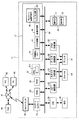
図2は、本発明の一実施形態に係る画像形成装置を示すもので、画像形成装置本体11内の構成を示すブロック図である。 FIG. 2 shows an image forming apparatus according to an embodiment of the present invention, and is a block diagram showing a configuration inside the image forming apparatus main body 11.
画像形成装置本体11には、CPU21が設けられている。CPU21は制御部211を含みPCIバス50に接続されている。PCIバスはPeripheral Component Interconnect Busの略である。PCIバス50には、ROM22、RAM23が接続されている。ROM22には、本体11の動作に必要な各種の制御プログラムが記憶されている。RAM23は、各種のデータを記憶する。また、本体11には、ネットワークインタフェース24が設けられ、ネットワークインタフェース24はネットワークコントローラ25を介してPCIバス50に接続されている。
The image forming apparatus main body 11 is provided with a
ネットワークインタフェース24はLANボードやFAXモデムなどを含み、ネットワーク41を介して外部機器、例えばPC42,43やファクシミリ装置44に接続されている。ネットワークコントローラ25は、ネットワークインタフェース24を介して外部機器との間のデータ送受信を制御するものである。
The network interface 24 includes a LAN board, a FAX modem, and the like, and is connected to external devices such as the
PCIバス50には、さらに前述したデータベース17が接続されている。データベース17には、不揮発性メモリ26、ログ記憶部27,画像記憶部28、及びサムネイル画像作成部29を含んでいる。不揮発性メモリ26、ログ記憶部27,画像記憶部28、及びサムネイル画像作成部29はPCIバス55に接続されている。またサムネイル画像作成部29は、ログ作成部291を有している。なお不揮発性メモリ26は、データベース17内ではなく、データベース17と分離して設け、PCIバス55に接続するようにしても良い。
The
PCIバス55にはさらに、コピー制御部30、スキャナ制御部31、プリンタ制御部32、FAX制御部33、操作パネル34がそれぞれ接続されている。また、PCIバス55にはIDE35を介してHDD(ハードディスク装置)36が接続されている。IDE35はHDD36をPCIバス55に接続するためのインタフェースであり、Integrated Device Electronicsの略である。操作パネル34は、前述した操作部12と表示部13を含む。
Further, a
コピー制御部30は、スキャナ14およびプリンタ15を使用した通常のコピー機能を制御する。スキャナ制御部31は、スキャナ14を使用したスキャン機能や、スキャンした画像データをPC42に記憶するファイル機能や、画像データを外部機器に送信するEメール機能を制御する。プリンタ制御部32は、プリンタ15を使用したプリント機能又はネットワークプリント機能を制御する。さらにファクシミリ制御部33は、ファクシミリ機能を制御する。またHDD36には、プリンタ15で印刷処理する際の画像データが記憶される。
The
CPU21の制御部211は、コピー制御部30、スキャナ制御部31、プリンタ制御部32、FAX制御部33を制御するジョブ管理部を構成する。
The
次に、本発明の画像形成装置の動作を説明する。本発明では、サムネイル画像の作成に主眼があるため、以下はサムネイル画像の作成を中心にして説明する。 Next, the operation of the image forming apparatus of the present invention will be described. In the present invention, since the focus is on the creation of thumbnail images, the following description will focus on the creation of thumbnail images.
本発明では、使用したジョブ機能(スキャン/コピー/FAX送受信/E-Mail送受信/ネットワーク印刷等)に対してジョブログを作成し、ジョブイメージを重畳してサムネイル画像を表示できるが、サムネイル画像を作成する際に、作成条件を設定し、ユーザ、部門、日時、ジョブの種類、プリントサイズ等を指定して、指定された条件のもとでサムネイル画像を作成する点に特徴がある。 In the present invention, a job log can be created for the used job function (scan / copy / fax transmission / reception / e-mail transmission / reception / network printing, etc.), and a thumbnail image can be displayed by superimposing the job image. When creating, a feature is that a creation condition is set, a user, a department, a date, a job type, a print size, and the like are designated, and a thumbnail image is created under the designated condition.
作成条件に合致するジョブが実行されると、そのときのジョブログを用いてサムネイル用のログ(以下サムネイルログと称す)が作成され、それにジョブイメージを重畳してサムネイル画像を表示するようにしたものである。 When a job that matches the creation conditions is executed, a log for thumbnails (hereinafter referred to as thumbnail log) is created using the job log at that time, and the thumbnail image is displayed by superimposing the job image on it. Is.
以下に、上記した作成条件について詳細に説明する。サムネイル画像の作成条件としては、例えば以下の(a)〜(e)が考えられる。 Hereinafter, the above-described creation conditions will be described in detail. As the thumbnail image creation conditions, for example, the following (a) to (e) are conceivable.
(a)「ユーザを指定する」:ユーザ管理が施されているMFP10ならば、ユーザ名、ユーザIDなどを指定し、指定されたユーザが行ったジョブに対してのみサムネイルログの保存を実行する。複数ユーザの選択が可能である。
(A) “Specify user”: If the
(b)「部門を指定する」:部門管理が施されているMFP10ならば、部門を指定し、指定された部門に所属するユーザが行ったジョブに対してのみサムネイルログの保存を実行する。複数部門の選択が可能である。
(B) “Designate department”: If the
(c)「日時を指定する」:日時の範囲を指定して、指定された日時の範囲内に行われたジョブに対してのみサムネイルログの保存を実行する。曜日指定や、所定の時間帯を指定するなど、複数範囲の選択が可能である。 (C) “Specify date and time”: A date and time range is specified, and thumbnail logs are saved only for jobs performed within the specified date and time range. A plurality of ranges can be selected, such as a day of the week or a predetermined time zone.
(d)「ジョブの種類を指定する」:ジョブの種類(スキャン/コピー/FAX送受信/E-Mail送受信/ネットワーク印刷等)を指定して、指定されたジョブが行われた場合のみ、サムネイルログの保存を実行する。複数種類のジョブの選択が可能である。 (D) “Specify the job type”: Specify the job type (scan / copy / fax transmission / reception / e-mail transmission / reception / network printing, etc.) and only when the specified job is performed, the thumbnail log Save the file. Multiple types of jobs can be selected.
(e)「サイズを指定する」:スキャンされた画像サイズもしくは、印刷用紙サイズを指定して、指定されたサイズのジョブが行われた場合のみ、サムネイルログの保存を実行する。複数サイズの選択が可能である。 (E) “Specify size”: The thumbnail log is saved only when a scanned image size or print paper size is specified and a job of the specified size is performed. Multiple sizes can be selected.
以上の、(a)〜(e)の条件は、複数選択することができ、複数選択された場合は、例えばOR又はAND条件として設定される。また、カラーコピーが実行された場合を条件にする等、他の条件設定も可能である。 A plurality of the above conditions (a) to (e) can be selected. When a plurality of conditions are selected, for example, an OR or AND condition is set. In addition, other conditions can be set, such as when a color copy is executed.
次に、サムネイル画像の保存の仕方と保存条件の設定の仕方について図3、図4を参照して説明する。ここで、MFP10は、部門管理が有効になっているMFPであるものとする。また、管理される部門として、「部門1」、「部門2」、「部門3」があると仮定する。
Next, how to store thumbnail images and how to set storage conditions will be described with reference to FIGS. Here, it is assumed that the
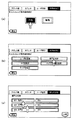
先ず、サムネイルログの保存機能を有効にするため、MFP10の管理者は、操作部12の設定/登録キーを操作して、表示部13に図3(a)で示す設定画面を表示する。管理者はこの画面からサムネイルログの保存を実行するためカーサルにより「有効」を選択する。
First, in order to validate the thumbnail log saving function, the administrator of the
次に、表示部12には図3(b)で示すように、サムネイルログの保存条件に関する画面が表示され、5つの条件設定用の選択画面が表示される。管理者は表示された条件の中から、任意の条件を複数選択できる。ここでは、サムネイルログの保存条件1として、「部門を指定」を選択するものとする。
Next, as shown in FIG. 3B, the
これにより、表示部12には図3(c)で示すように、現在登録されている部門の一覧が表示される。管理者は表示された部門の一覧の中から、任意の部門を選択する。ここでは、「部門1」と「部門2」を指定する。指定後は、「次頁」のアイコンを選択することで図4(a)の画面が表示される。
As a result, a list of currently registered departments is displayed on the
図4(a)の画面は、図3(b)の保存条件に関する画面と同じであるが、条件1として部門が指定されたため、「部門を指定」の項目は異なる色で表示される。図4(a)において、管理者は、条件1のほかに、任意の条件を選択することができる。ここでは条件2として、「ジョブの種類を指定」を選択するものとする。
The screen shown in FIG. 4A is the same as the screen related to the storage condition shown in FIG. 3B. However, since the department is designated as
「ジョブの種類を指定」を選択すると、図4(b)で示す画面が表示される。図4(b)ではMFP10が処理可能なジョブの種類が表示され、例えばスキャン/コピー/FAX送信/FAX受信/E-Mail送信/E-Mail受信/ネットワーク印刷の項目が表示される。管理者は上記のジョブの種類の中から任意のジョブを選択できる。ここでは、「コピー」と「FAX送信」を指定するものとする。これにより、図4(c)で示すように、「部門を指定」と「ジョブの種類を指定」の2条件が設定されたことになる。
When “specify job type” is selected, a screen shown in FIG. 4B is displayed. In FIG. 4B, job types that can be processed by the
こうして、サムネイルログの保存と保存条件の設定を完了する。設定が完了すると、CPU21は設定された内容を不揮発性メモリ26に記憶する。
Thus, the thumbnail log storage and storage condition setting are completed. When the setting is completed, the
図5は、不揮発性メモリ26に記憶された内容を示す図であり、サムネイルログの保存機能は「有効」であり、サムネイルログの保存条件は「有り」となっている。設定された条件のうち、部門は、「部門1」と「部門2」が設定されている。またジョブの種類は、「コピー」と「FAX送信」が設定されていることを表している。即ち、図5の例は、「部門1」と「部門2」に所属するユーザがコピー又はFAX送信を実施した場合にサムネイルログの保存が実行されることになる。
FIG. 5 is a diagram showing the contents stored in the
次に、実際にMFP10を使用してジョブが実施された場合の、サムネイルログ保存までの制御について説明する。ここでは先ず、「部門1」に所属しているユーザがコピーを実施した場合の制御について述べる。
Next, control until thumbnail log storage when a job is actually performed using the
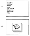
「部門1」に所属しているユーザが、「部門1」としてMFP10にログインし、コピーを行うと、CPU21は、実行されたジョブの種類を判別し、図6(a)に示すようなジョブログを作成してログ記憶部27に格納する。ジョブログとしては、ジョブ番号(ジョブの通し番号)、部門名(及びユーザ管理を実施している場合にはユーザ名)、実施日時、ジョブの種類、原稿サイズ、用紙サイズ、枚数の情報があり、これらをジョブログとしてログ記憶部27に格納する。
When a user who belongs to “
CPU21は、コピー動作及びジョブログの格納が終了した後に、サムネイルログの保存機能が「有効」と設定されているか、またサムネイルログの保存条件が設定されているかどうかを、不揮発性メモリ26の内容を参照して判断する。今回のケースでは、サムネイルログの保存機能が「有効」であり、条件が設定されているため、ログ記憶部27に格納されたデータの中から条件に合致するジョブログを抽出する。
After the copy operation and job log storage are completed, the
また、画像記憶部28には、図6(b)に示すようなジョブイメージのデータが記憶されている。例えばコピー、ネットワーク印刷等の種類を表すジョブイメージのデータが記憶されており、実際に実行されたジョブ(今回の場合はコピー)のイメージデータが抽出される。
The
ログ記憶部27からのジョブログの抽出、及び画像記憶部28からのイメージデータの抽出は、CPU21の制御のもとにサムネイル画像作成部29が行う。サムネイル画像作成部29のログ作成部291は、抽出したジョブログをもとにサムネイルログを作成し、サムネイル画像作成部29は、ログ作成部291で作成されたサムネイルログと、画像記憶部28から抽出されたジョブイメージデータを利用してサムネイル画像を作成する。
Extraction of the job log from the
こうして、サムネイル画像作成部29では、条件に従ってサムネイル画像を作成して保管し、かつサムネイルの一覧表を保管する。したがって管理者はPC43を操作して、データベース17にアクセスすることにより、サムネイル画像を見ることが可能になる。
In this way, the thumbnail
図7は、本発明によるサムネイル画像の作成と、その表示動作を説明する図である。図7において、100は管理者であり、PC43を操作する。また200は「部門1」に属するユーザであり、MPF10を利用してコピーする人と仮定する。また300は、「部門2」に属するユーザであり、PC42を操作してネットワーク印刷する人と仮定する。
FIG. 7 is a diagram for explaining the creation and display operation of thumbnail images according to the present invention. In FIG. 7,
ユーザ200がMFP10を利用してコピーを実行すると、コピーのジョブ履歴を示すサムネイルログ202と、コピーのジョブイメージ203とで成るサムネイル画像201が作成される。また、ユーザ300がPC42からMFP10にアクセスしてネットワーク印刷を実行すると、ネットワーク印刷を示すサムネイルログ302と、ネットワーク印刷のジョブイメージ303で成るサムネイル画像301が作成される。
When the
一方、管理者100は、PC43を操作してMFP10にアクセスすることで、ユーザ200,300によるMPF10の使用履歴を参照することができる。例えばPC43の画面にはサムネイル一覧101が表示され、一覧の中のコピーのジョブイメージ203を選択してクリックすると、点線枠で示すサムネイルログ202が表示される。
On the other hand, the
サムネイルログ202は、ジョブ番号、ユーザ名、部門名、日時、ジョブの種類、原稿サイズ、用紙サイズ、枚数の情報からなり、管理者100は、サムネイルログを確認することでジョブの実行内容を知ることができる。これにより例えば、許可されていないユーザや、他部門のユーザがコピーしていないかを把握することができる。また、一覧101の中のネットワーク印刷のジョブイメージ303を選択すると、サムネイルログ302が表示される。
The
また、予め設定した条件に合致しない部門のユーザがMFP10を利用したり、予め設定した条件に合致しないジョブが実行された場合はサムネイル表示されることはなく、不要な情報を削除することができる。したがって管理者が設定した条件のもとにサムネイル画像が作成されるため、サムネイル画像の中から特定の画像を検索する場合は、容易に検索することができる。
Further, when a user in a department that does not meet a preset condition uses the
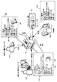
図8は、サムネイルログの作成処理の動作を説明するフローチャートである。尚、図8において、Aは不揮発性メモリ26に格納されたサムネイルログの保存条件等を示す参照図であり、Bはログ記憶部27に記憶されるジョブログを示す参照図であり、*1〜*6の矢印符号は、フローチャートの判断ステップにおいて参照される項目を示している。
FIG. 8 is a flowchart for explaining the operation of the thumbnail log creation process. In FIG. 8, A is a reference diagram showing storage conditions for thumbnail logs stored in the
ステップS1は、動作の開始ステップであり、ステップS2でジョブが実行される。ここでは仮にコピーが実行された場合を示している。ステップS3では、コピー処理に応答して参照図Bに示すジョブログの作成が行われ、データベース17のログ記憶部27に記憶される。
Step S1 is an operation start step, and the job is executed in step S2. Here, a case where copying is executed is shown. In step S <b> 3, the job log shown in the reference diagram B is created in response to the copy process and stored in the
次のステップS4では*1を参照し、サムネイルログの保存機能が有効か否か判断される。有効であればステップS5に進み、有効でない場合は終了ステップS14に移行し、サムネイルログの作成は行われない。ステップS5では、*2を参照してサムネイルログの保存条件の有無を判断する。条件が設定されている場合はステップS6の総和ループに進み、条件が設定されていない場合はステップS13に移行する。 In the next step S4, * 1 is referred to and it is determined whether or not the thumbnail log saving function is valid. If it is valid, the process proceeds to step S5. If it is not valid, the process proceeds to end step S14, and no thumbnail log is created. In step S5, the presence / absence of thumbnail log storage conditions is determined with reference to * 2. If the condition is set, the process proceeds to the sum loop of step S6. If the condition is not set, the process proceeds to step S13.
ステップS6の総和ループの「N:1,1,5」は、Nの初期値が1で、1回だけインクリメント。Nの最大値は5であり、N=5での処理が終わったら、全体の処理は終了する。CPU21は、参照図Aの保存条件と、参照図Bのジョブログとを、以降の5つのステップで比較する。
“N: 1, 1, 5” of the sum loop of step S6 has an initial value of 1 and is incremented only once. The maximum value of N is 5, and when the process with N = 5 is finished, the entire process is finished. The
ステップS7〜ステップS11は、それぞれ、「ユーザを指定しているか」、「部門を指定しているか」、「ジョブを指定しているか」、「日時を指定しているか」、「サイズを指定しているか」を判断する。それぞれのステップS7〜S11の判断結果がNOであれば順次、次のステップを介してステップS12に進む。ステップS7〜S11の判断結果がYESであれば、それぞれステップS17〜S21に移行して次の判断が行われる。 Steps S7 to S11 respectively specify “user is specified”, “department is specified”, “job is specified”, “date / time is specified”, and “size is specified”. It is judged. If the determination result of each step S7 to S11 is NO, the process proceeds to step S12 sequentially through the next step. If the determination result of steps S7 to S11 is YES, the process proceeds to steps S17 to S21, and the next determination is made.
ステップS17〜S21は、参照図Bの情報が参照図Aの情報の中に含まれているかを判断するものであり、それぞれのステップS17〜S21での判断がNOであればステップS14に移行し、ステップS17〜S21での判断がYESであればステップS12に移行する。 Steps S17 to S21 are for determining whether the information in the reference diagram B is included in the information in the reference diagram A. If the determinations in the respective steps S17 to S21 are NO, the process proceeds to step S14. If the determination in steps S17 to S21 is YES, the process proceeds to step S12.
今回の例では、部門とジョブの種類について条件が設定されているため、ステップS18ではどの部門が指定されているかを*3と*5を参照して判断する。 In this example, conditions are set for the department and the job type, so in step S18, which department is designated is determined with reference to * 3 and * 5.
この場合、参照図Aの設定条件が「部門1」と「部門2」であり、参照図Bの中に「部門1」が含まれているため、ステップS18の判断はYESとなり、ステップS12に進む。同様に、ステップS19ではどのジョブ種類が指定されているかを*4と*6を参照して判断する。参照図Aの設定条件が「コピー」と「FAX送信」であり、参照図Bの中に「コピー」が含まれているため、ステップS19の判断はYESとなり、ステップS12に進む。
In this case, the setting conditions of the reference diagram A are “
その他の条件は設定されていないため、ステップS12では、ループ処理を5回実行した後、設定されている全てのサムネイルログの保存条件が満たされたと判断し、次のステップS13において、ログ作成部291はサムネイルログを作成し、格納処理を実行して終了ステップS14へ進む。
Since no other conditions are set, in step S12, after executing the loop process five times, it is determined that the storage conditions for all the set thumbnail logs are satisfied, and in the next step S13, the log creation unit In
こうして、サムネイル画像作成部29は、ログ作成部291で作成されたサムネイルログを利用してサムネイル画像を作成することができる。サムネイルログと、画像記憶部28に記憶されたイメージジョブを用いることでサムネイル画像はより見やすいものとなる。
Thus, the thumbnail
このように、本発明では、サムネイル画像の作成条件を指定することによって、サムネイル画像データの肥大化を防ぐことができる。サムネイル画像データの保存容量が小さい場合、古くなったサムネイル画像データは順次削除されるのが一般的であり、このため保存期間が短くなるが、本発明では必要なサムネイル画像のみを保存するため保存期間が長くなる。 Thus, according to the present invention, it is possible to prevent enlargement of thumbnail image data by specifying the thumbnail image creation conditions. When the storage capacity of the thumbnail image data is small, the old thumbnail image data is generally deleted sequentially, so that the storage period is shortened. However, in the present invention, only the necessary thumbnail images are stored. The period becomes longer.
また、サムネイル画像の作成は指定されたものに限定されることから、必要なサムネイル画像を検索することが容易になる。 In addition, since the creation of thumbnail images is limited to the designated one, it becomes easy to search for necessary thumbnail images.
尚、以上の説明に限定されることなく、特許請求の範囲を逸脱しない範囲で種々の変形が可能である。 The present invention is not limited to the above description, and various modifications can be made without departing from the scope of the claims.
10…MFP(画像形成装置)
11…画像形成装置本体
12…操作部
13…表示部
14…スキャナ
15…プリンタ
16…カセット
21…CPU
22…ROM
23…RAM
24…ネットワークインタフェース
25…ネットワークコントローラ
26…不揮発性メモリ
27…ログ記憶部
28…画像記憶部
29…サムネイル画像作成部
30…コピー制御部
31…スキャナ制御部
32…プリンタ制御部
33…FAX制御部
34…操作パネル
35…IDE
36…HDD
41…ネットワーク
50…PCIバス
10. MFP (image forming apparatus)
DESCRIPTION OF SYMBOLS 11 ... Image forming apparatus
22 ... ROM
23 ... RAM
24 ...
36 ... HDD
41 ...
Claims (13)
サムネイル用のログの保存機能を有効もしくは無効に選択でき、有効の場合に前記サムネイル画像の作成条件を設定可能にする条件設定部と、
前記サムネイル用のログの保存機能が有効の場合において、前記サムネイル画像の作成条件に合致するジョブが実行されたときに、実行されたジョブに関するジョブログを用いて前記サムネイル用のログを作成するログ作成部と、
前記実行されたジョブの種類を表すジョブイメージを作成するジョブイメージ作成部と、
前記サムネイル用のログと前記ジョブイメージからなるサムネイル画像を作成し保存するサムネイル画像作成部と、
を具備したことを特徴とする画像形成装置。 An image forming apparatus capable of executing a plurality of jobs and capable of generating a thumbnail image representing an execution history of the job,
The storage function of the log of the thumbnail can be selected enable or disable, a condition setting unit that can set the forming conditions of the thumbnail image when enabled,
When the thumbnail log storage function is enabled, when a job that matches the thumbnail image creation conditions is executed, a log for creating the thumbnail log using a job log related to the executed job The creation department;
A job image creation unit for creating a job image representing the type of the executed job;
A thumbnail image creation unit for creating and saving a thumbnail image composed of the log for the thumbnail and the job image;
An image forming apparatus comprising:
サムネイル用のログの保存機能を有効もしくは無効に選択でき、有効の場合に前記サムネイル画像の作成条件を設定可能な条件設定部と、
前記条件設定部によって設定されたサムネイル画像の作成条件を記憶する不揮発性メモリと、
前記複数のジョブのいずれかが実行されたときにジョブログを生成して記憶する第1の記憶部と、
前記複数のジョブの種類を表すジョブイメージを記憶する第2の記憶部と、
前記サムネイル用のログの保存機能が有効の場合において、前記サムネイル画像の作成条件に合致するジョブが実行されたときに、前記実行されたジョブに関するジョブログを用いて前記サムネイル用のログを作成し、前記サムネイル用のログ及び前記作成条件に合致するジョブイメージからなるサムネイル画像を作成し保存するサムネイル画像作成部と、
を具備したことを特徴とする画像形成装置。 An image forming apparatus capable of executing a plurality of jobs and capable of generating a thumbnail image representing an execution history of the job,
A condition setting unit that can select whether to enable or disable the thumbnail log storage function, and can set the creation condition of the thumbnail image when enabled ,
A non-volatile memory for storing thumbnail image creation conditions set by the condition setting unit;
A first storage unit for generating and storing di Yoburogu when any of said plurality of jobs are executed,
A second storage unit that stores job images representing the types of the plurality of jobs;
When the thumbnail log storage function is enabled, when a job that satisfies the thumbnail image creation conditions is executed, the thumbnail log is created using a job log related to the executed job. A thumbnail image creation unit for creating and saving a thumbnail image composed of a job image that matches the creation log and the log for the thumbnail ;
An image forming apparatus comprising:
サムネイル用のログの保存機能を有効もしくは無効に選択でき、有効の場合に前記ジョブの実行履歴を表すサムネイル画像を作成するため、サムネイル画像の作成条件を設定し、
前記設定されたサムネイル画像の作成条件を第1の記憶部に記憶し、
前記複数のジョブの種類を表すジョブイメージを第2の記憶部に記憶し、
前記サムネイル用のログの保存機能が有効の場合において、前記サムネイル画像の作成条件に合致するジョブが実行されたときに、実行されたジョブに関するジョブログを生成し、
前記実行されたジョブに関するジョブログを用いて前記サムネイル用のログを作成し、
前記サムネイル用のログ及び前記作成条件に合致するジョブイメージからなるサムネイル画像を作成し保存することを特徴とするサムネイル画像作成方法。 A thumbnail image creation method in an image forming apparatus capable of executing a plurality of jobs,
The thumbnail log storage function can be selected to be valid or invalid, and when it is valid, a thumbnail image representing the job execution history is created.
Storing the set thumbnail image creation conditions in the first storage unit;
Storing job images representing the types of the plurality of jobs in a second storage unit;
When the thumbnail log storage function is enabled, when a job matching the thumbnail image creation conditions is executed, a job log relating to the executed job is generated,
Create a log for the thumbnail using a job log for the executed job,
A thumbnail image creation method comprising: creating and storing a thumbnail image composed of a log for the thumbnail and a job image that matches the creation condition .
Applications Claiming Priority (2)
| Application Number | Priority Date | Filing Date | Title |
|---|---|---|---|
| US11/425,310 US20070291284A1 (en) | 2006-06-20 | 2006-06-20 | Image Forming Apparatus and Thumbnail Image Generating Method |
| US11/425,310 | 2006-06-20 |
Publications (3)
| Publication Number | Publication Date |
|---|---|
| JP2008005500A JP2008005500A (en) | 2008-01-10 |
| JP2008005500A5 JP2008005500A5 (en) | 2010-05-06 |
| JP5039446B2 true JP5039446B2 (en) | 2012-10-03 |
Family
ID=38861218
Family Applications (1)
| Application Number | Title | Priority Date | Filing Date |
|---|---|---|---|
| JP2007162744A Active JP5039446B2 (en) | 2006-06-20 | 2007-06-20 | Image forming apparatus and thumbnail image creating method |
Country Status (3)
| Country | Link |
|---|---|
| US (1) | US20070291284A1 (en) |
| JP (1) | JP5039446B2 (en) |
| CN (1) | CN101094284B (en) |
Families Citing this family (13)
| Publication number | Priority date | Publication date | Assignee | Title |
|---|---|---|---|---|
| JP4710763B2 (en) * | 2006-08-31 | 2011-06-29 | 富士ゼロックス株式会社 | Image processing program, instruction device, and image processing system |
| JP2008209985A (en) * | 2007-02-23 | 2008-09-11 | Canon Inc | Data processor, electronic document registration method and computer program |
| JP4930312B2 (en) * | 2007-10-02 | 2012-05-16 | ブラザー工業株式会社 | Information processing device |
| JP5264334B2 (en) * | 2008-07-09 | 2013-08-14 | キヤノン株式会社 | Information processing apparatus and information processing method |
| JP5430181B2 (en) * | 2009-03-10 | 2014-02-26 | キヤノン株式会社 | Image forming apparatus, control method thereof, and program |
| JP5366698B2 (en) * | 2009-08-04 | 2013-12-11 | キヤノン株式会社 | Job history information audit system, image forming apparatus, control method, and program |
| CN102196131A (en) * | 2010-03-17 | 2011-09-21 | 株式会社东芝 | FAX job managing apparatus, FAX transmission processing method, and FAX transmission processing system |
| JP2011259395A (en) * | 2010-06-11 | 2011-12-22 | Canon Inc | Image forming apparatus, control method, and program |
| JP2013110679A (en) * | 2011-11-24 | 2013-06-06 | Canon Inc | Information processor, and control method and control program of the same |
| JP5482808B2 (en) * | 2012-01-30 | 2014-05-07 | コニカミノルタ株式会社 | Management system, management server and program |
| JP6751285B2 (en) * | 2015-06-18 | 2020-09-02 | キヤノン電子株式会社 | Image forming apparatus, image forming method, program, and image forming system |
| JP6778420B2 (en) * | 2018-10-22 | 2020-11-04 | 株式会社リコー | Image forming device |
| CN110248209B (en) * | 2019-07-19 | 2021-06-15 | 湖南快乐阳光互动娱乐传媒有限公司 | Transmission method and system for bullet screen anti-shielding mask information |
Family Cites Families (31)
| Publication number | Priority date | Publication date | Assignee | Title |
|---|---|---|---|---|
| JP3622412B2 (en) * | 1997-03-25 | 2005-02-23 | セイコーエプソン株式会社 | Printing apparatus, printing method, and printing system |
| US6424429B1 (en) * | 1997-11-14 | 2002-07-23 | Ricoh Company, Ltd. | File system and a recording medium with a program used in the system stored therein |
| JPH11308422A (en) * | 1998-04-21 | 1999-11-05 | Toshiba Corp | Image forming device and image forming method |
| US7170632B1 (en) * | 1998-05-20 | 2007-01-30 | Fuji Photo Film Co., Ltd. | Image reproducing method and apparatus, image processing method and apparatus, and photographing support system |
| JP4034451B2 (en) * | 1998-12-07 | 2008-01-16 | 株式会社東芝 | Document input system and document input method |
| US6782402B1 (en) * | 1999-05-06 | 2004-08-24 | Seiko Epson Corporation | Network management system, computer system, copy server, file server, network copy file management method, and computer readable medium |
| JP3571988B2 (en) * | 2000-02-29 | 2004-09-29 | シャープ株式会社 | Display control device of image forming apparatus |
| JP3397200B2 (en) * | 2000-07-14 | 2003-04-14 | 村田機械株式会社 | Facsimile server |
| JP3760733B2 (en) * | 2000-07-18 | 2006-03-29 | 富士ゼロックス株式会社 | Scan system and scan document connection method, medium recording control program, server, and scanner |
| JP2002166630A (en) * | 2000-09-19 | 2002-06-11 | Fuji Xerox Co Ltd | Image inputting device and image outputting system |
| JP2002232588A (en) * | 2001-01-31 | 2002-08-16 | Canon Inc | Image communication unit, its control method and program |
| US20020145750A1 (en) * | 2001-04-09 | 2002-10-10 | Hachirou Honda | Printing materials production supporting apparatus, printing materials production supporting system, and printing materials production supporting program |
| JP3646931B2 (en) * | 2001-08-29 | 2005-05-11 | セイコーエプソン株式会社 | Image retouching program |
| US7315987B2 (en) * | 2002-01-15 | 2008-01-01 | Konica Corporation | Image administration method, image administration apparatus and image administration program |
| US7965399B2 (en) * | 2002-02-18 | 2011-06-21 | Canon Kabushiki Kaisha | Image processing apparatus, information processing apparatus, and information output method |
| JP2003241932A (en) * | 2002-02-20 | 2003-08-29 | Matsushita Electric Ind Co Ltd | Printer and printer system |
| JP4214804B2 (en) * | 2003-03-10 | 2009-01-28 | セイコーエプソン株式会社 | Log transmission device, method and program thereof |
| US20040243920A1 (en) * | 2003-05-29 | 2004-12-02 | Kabushiki Kaisha Toshiba | Document input/output journal management system and method |
| US7400785B2 (en) * | 2003-08-13 | 2008-07-15 | Hewlett-Packard Development Company, L.P. | Systems and methods for associating images |
| US20050094161A1 (en) * | 2003-11-05 | 2005-05-05 | Do Tae-Hoi | Image forming method and image forming apparatus |
| JP4227500B2 (en) * | 2003-11-21 | 2009-02-18 | キヤノン株式会社 | History management system, history management method, program, and recording medium |
| JP4464176B2 (en) * | 2004-03-30 | 2010-05-19 | キヤノン株式会社 | Information processing apparatus and method, job management system, and program |
| JP2005324450A (en) * | 2004-05-14 | 2005-11-24 | Canon Inc | Image forming apparatus, information processing apparatus, job displaying and controlling method, storage medium storing computer-readable program and program |
| JP3809840B2 (en) * | 2004-09-09 | 2006-08-16 | コニカミノルタビジネステクノロジーズ株式会社 | Data management apparatus, image output apparatus, data management method, and computer program |
| US20060077416A1 (en) * | 2004-09-20 | 2006-04-13 | Kabushiki Kaisha Toshiba | Image forming apparatus and method of controlling apparatus |
| JP2006094070A (en) * | 2004-09-22 | 2006-04-06 | Sharp Corp | Image processing apparatus |
| JP2006103158A (en) * | 2004-10-05 | 2006-04-20 | Canon Inc | Printer, print document processing method and computer program |
| JP2005102249A (en) * | 2004-10-15 | 2005-04-14 | Konica Minolta Holdings Inc | Image-forming device |
| JP4196971B2 (en) * | 2005-07-06 | 2008-12-17 | コニカミノルタビジネステクノロジーズ株式会社 | Data processing system, data processing apparatus, data processing method, and data processing program |
| JP4229100B2 (en) * | 2005-08-15 | 2009-02-25 | コニカミノルタビジネステクノロジーズ株式会社 | Image processing device |
| JP3802551B2 (en) * | 2005-12-05 | 2006-07-26 | シャープ株式会社 | Image forming apparatus |
-
2006
- 2006-06-20 US US11/425,310 patent/US20070291284A1/en not_active Abandoned
-
2007
- 2007-06-20 JP JP2007162744A patent/JP5039446B2/en active Active
- 2007-06-20 CN CN2007101114495A patent/CN101094284B/en not_active Expired - Fee Related
Also Published As
| Publication number | Publication date |
|---|---|
| CN101094284A (en) | 2007-12-26 |
| CN101094284B (en) | 2010-08-04 |
| US20070291284A1 (en) | 2007-12-20 |
| JP2008005500A (en) | 2008-01-10 |
Similar Documents
| Publication | Publication Date | Title |
|---|---|---|
| JP5039446B2 (en) | Image forming apparatus and thumbnail image creating method | |
| JP4766667B2 (en) | Display control apparatus, control method therefor, and program | |
| JP5252910B2 (en) | INPUT DEVICE, INPUT DEVICE CONTROL METHOD, AND PROGRAM | |
| JP2007034847A (en) | Retrieval apparatus and retrieval method | |
| JP4245055B2 (en) | Image processing system, image processing apparatus, job processing method, and program | |
| US9641720B2 (en) | Information processing apparatus searching operation/job log information based on selection of displayed job/operation log information | |
| JP2008234203A (en) | Image processing apparatus | |
| US8867091B2 (en) | Image processing system, image processing apparatus, image scanning apparatus, and control method and program for image processing system | |
| US20100202007A1 (en) | Image processing apparatus, control method thereof, and computer program | |
| JP5284322B2 (en) | Display control apparatus, control method therefor, and program | |
| JP2008289130A (en) | Copier device capable of electronically storing and recalling copied document | |
| JP2023015926A (en) | Information processing device and information processing program | |
| JP2012158046A (en) | Image forming apparatus | |
| JP6173522B2 (en) | INPUT DEVICE, INPUT DEVICE CONTROL METHOD, AND PROGRAM | |
| JP2011028437A (en) | Image forming apparatus | |
| US8310712B2 (en) | Image forming controlling apparatus, image forming controlling method, and image forming controlling program embodied on computer readable recording medium | |
| JP5619208B2 (en) | Input device, input method, and program | |
| JP6701397B2 (en) | Input device, input device control method, and program | |
| JP6907370B2 (en) | Item input device, item input program, and item input method | |
| JP4937168B2 (en) | Image forming apparatus | |
| JP6479100B2 (en) | INPUT DEVICE, INPUT DEVICE CONTROL METHOD, AND PROGRAM | |
| JP5442081B2 (en) | Display control apparatus, control method therefor, and program | |
| JP2007028058A (en) | Image forming apparatus and computer program | |
| JP2009225183A (en) | Image forming apparatus | |
| JP5932925B2 (en) | INPUT DEVICE, INPUT DEVICE CONTROL METHOD, AND PROGRAM |
Legal Events
| Date | Code | Title | Description |
|---|---|---|---|
| A521 | Written amendment |
Free format text: JAPANESE INTERMEDIATE CODE: A523 Effective date: 20100319 |
|
| A621 | Written request for application examination |
Free format text: JAPANESE INTERMEDIATE CODE: A621 Effective date: 20100319 |
|
| A977 | Report on retrieval |
Free format text: JAPANESE INTERMEDIATE CODE: A971007 Effective date: 20110912 |
|
| A131 | Notification of reasons for refusal |
Free format text: JAPANESE INTERMEDIATE CODE: A131 Effective date: 20110920 |
|
| A521 | Written amendment |
Free format text: JAPANESE INTERMEDIATE CODE: A523 Effective date: 20111118 |
|
| TRDD | Decision of grant or rejection written | ||
| A01 | Written decision to grant a patent or to grant a registration (utility model) |
Free format text: JAPANESE INTERMEDIATE CODE: A01 Effective date: 20120619 |
|
| A01 | Written decision to grant a patent or to grant a registration (utility model) |
Free format text: JAPANESE INTERMEDIATE CODE: A01 |
|
| A61 | First payment of annual fees (during grant procedure) |
Free format text: JAPANESE INTERMEDIATE CODE: A61 Effective date: 20120709 |
|
| FPAY | Renewal fee payment (event date is renewal date of database) |
Free format text: PAYMENT UNTIL: 20150713 Year of fee payment: 3 |
|
| R150 | Certificate of patent or registration of utility model |
Ref document number: 5039446 Country of ref document: JP Free format text: JAPANESE INTERMEDIATE CODE: R150 Free format text: JAPANESE INTERMEDIATE CODE: R150 |