JP5038148B2 - System and method for performing cyclic redundancy check - Google Patents
System and method for performing cyclic redundancy check Download PDFInfo
- Publication number
- JP5038148B2 JP5038148B2 JP2007543424A JP2007543424A JP5038148B2 JP 5038148 B2 JP5038148 B2 JP 5038148B2 JP 2007543424 A JP2007543424 A JP 2007543424A JP 2007543424 A JP2007543424 A JP 2007543424A JP 5038148 B2 JP5038148 B2 JP 5038148B2
- Authority
- JP
- Japan
- Prior art keywords
- crc
- data
- mddi
- packet
- link
- Prior art date
- Legal status (The legal status is an assumption and is not a legal conclusion. Google has not performed a legal analysis and makes no representation as to the accuracy of the status listed.)
- Expired - Fee Related
Links
Images


Classifications
-
- H—ELECTRICITY
- H04—ELECTRIC COMMUNICATION TECHNIQUE
- H04L—TRANSMISSION OF DIGITAL INFORMATION, e.g. TELEGRAPHIC COMMUNICATION
- H04L7/00—Arrangements for synchronising receiver with transmitter
- H04L7/04—Speed or phase control by synchronisation signals
- H04L7/10—Arrangements for initial synchronisation
-
- H—ELECTRICITY
- H04—ELECTRIC COMMUNICATION TECHNIQUE
- H04B—TRANSMISSION
- H04B7/00—Radio transmission systems, i.e. using radiation field
- H04B7/24—Radio transmission systems, i.e. using radiation field for communication between two or more posts
-
- G—PHYSICS
- G09—EDUCATION; CRYPTOGRAPHY; DISPLAY; ADVERTISING; SEALS
- G09G—ARRANGEMENTS OR CIRCUITS FOR CONTROL OF INDICATING DEVICES USING STATIC MEANS TO PRESENT VARIABLE INFORMATION
- G09G5/00—Control arrangements or circuits for visual indicators common to cathode-ray tube indicators and other visual indicators
- G09G5/003—Details of a display terminal, the details relating to the control arrangement of the display terminal and to the interfaces thereto
- G09G5/006—Details of the interface to the display terminal
-
- H—ELECTRICITY
- H04—ELECTRIC COMMUNICATION TECHNIQUE
- H04L—TRANSMISSION OF DIGITAL INFORMATION, e.g. TELEGRAPHIC COMMUNICATION
- H04L7/00—Arrangements for synchronising receiver with transmitter
- H04L7/04—Speed or phase control by synchronisation signals
- H04L7/048—Speed or phase control by synchronisation signals using the properties of error detecting or error correcting codes, e.g. parity as synchronisation signal
-
- G—PHYSICS
- G09—EDUCATION; CRYPTOGRAPHY; DISPLAY; ADVERTISING; SEALS
- G09G—ARRANGEMENTS OR CIRCUITS FOR CONTROL OF INDICATING DEVICES USING STATIC MEANS TO PRESENT VARIABLE INFORMATION
- G09G2370/00—Aspects of data communication
- G09G2370/04—Exchange of auxiliary data, i.e. other than image data, between monitor and graphics controller
- G09G2370/045—Exchange of auxiliary data, i.e. other than image data, between monitor and graphics controller using multiple communication channels, e.g. parallel and serial
-
- G—PHYSICS
- G09—EDUCATION; CRYPTOGRAPHY; DISPLAY; ADVERTISING; SEALS
- G09G—ARRANGEMENTS OR CIRCUITS FOR CONTROL OF INDICATING DEVICES USING STATIC MEANS TO PRESENT VARIABLE INFORMATION
- G09G2370/00—Aspects of data communication
- G09G2370/10—Use of a protocol of communication by packets in interfaces along the display data pipeline
Description
本発明は、一般に、データ通信に関する。更に詳しくは、本発明は、巡回冗長検査を使用するデジタル送信リンクに関する。 The present invention generally relates to data communications. More particularly, the present invention relates to digital transmission links that use cyclic redundancy checking.
コンピュータ、モバイル電話、モバイル電話カメラ及びビデオキャプチャデバイス、パーソナルデジタルアシスタント、電子ゲーム関連製品及び様々なビデオ技術(例えば、DVDおよび高解像度VCR)は、ますますより高い解像度の静止、ビデオ、ビデオオンデマンド、及びグラフィックイメージのキャプチャ及び表示のために、ここ数年の間に著しく進化した。そのようなビジュアルイメージを、例えばCDタイプの音再生、DVD、及び関連するオーディオ信号出力を有するその他のデバイスのような高品質オーディオデータと組み合わせることによって、より現実的で、内容が豊富な、すなわちエンドユーザに対する真のマルチメディア体験を生み出す。更に、ユーザに対してオーディオのみを提供するために、例えばMP3プレーヤのように高いモバイル性の高品質なサウンドシステムや、音楽転送機構が開発された。 Computers, mobile phones, mobile phone cameras and video capture devices, personal digital assistants, electronic gaming related products and various video technologies (eg DVD and high resolution VCR) are becoming increasingly higher resolution stills, video, video on demand And has evolved significantly over the last few years for the capture and display of graphic images. By combining such visual images with high-quality audio data such as CD-type sound reproduction, DVD and other devices with associated audio signal output, it is more realistic and rich in content, ie Create a true multimedia experience for end users. Further, in order to provide only audio to the user, a high-quality sound system with high mobility such as an MP3 player and a music transfer mechanism have been developed.
高品質データ表示の進化によって、データ品質が低下したり害されることなく、高データレートでのデータ転送が可能な専用インタフェースを確立する必要性が生じた。そのような1つのインタフェースは、モバイルディスプレイデジタルインタフェース(MDDI)であり、例えば、カメラを有するセルラ電話の下部クラムシェルと上部クラムシェルとの間での高速データ交換のために使用される。MDDIは、コスト効率が良く、低電力消費であり、ホストとクライアントとの間の短距離通信リンクによる超高速データ転送を可能にする転送メカニズムである。MDDIは、最低でも、4本のワイヤと、双方向データ転送のための電力を必要とし、現在の技術では、毎秒最大3.2ギガビットの最大帯域幅を配信することができる。 The evolution of high quality data display has created a need to establish a dedicated interface that can transfer data at high data rates without degrading or harming data quality. One such interface is the mobile display digital interface (MDDI), which is used, for example, for high-speed data exchange between the lower clamshell and upper clamshell of a cellular phone with a camera. MDDI is a transfer mechanism that is cost effective, has low power consumption, and enables ultra-high speed data transfer over a short-range communication link between a host and a client. MDDI requires at least four wires and power for bidirectional data transfer, and current technology can deliver a maximum bandwidth of up to 3.2 gigabits per second.
MDDI及びその他のデータインタフェースは、インタフェースを介して高速なデータレートを効率的に提供することができるが、パフォーマンスを最適化し、かつ例えばMDDIリンクのようなデジタル送信リンクを効率的に使用するニーズが高まっている。
本発明は、リンク初期化処理の改善、及びシステムエラー情報の交換のために、巡回冗長検査(CRC)を実施するシステム及び方法を提供し、これによって、デジタル送信リンクがより効率的に利用できるようになる。本発明の1つの局面では、ユニークパターン検出器、CRCジェネレータ、CRCイニシャライザ、及びCRCベリファイヤを含む巡回冗長検査(CRC)チェッカが提供される。CRCチェッカは、ユニークパターンのためにCRCジェネレータを予め実装する。CRCジェネレータが予め実装されるので、デジタル送信リンクによって受信されたデータストリーム内のユニークパターンを取得すると、CRCチェッカは、データをキュー及び格納する必要なくCRCのチェックを進める。 The present invention provides a system and method for performing cyclic redundancy check (CRC) for improved link initialization processing and exchange of system error information, thereby enabling more efficient use of digital transmission links. It becomes like this. In one aspect of the present invention, a cyclic redundancy check (CRC) checker is provided that includes a unique pattern detector, a CRC generator, a CRC initializer, and a CRC verifier. The CRC checker pre-installs a CRC generator for the unique pattern. Since the CRC generator is pre-implemented, upon obtaining a unique pattern in the data stream received by the digital transmission link, the CRC checker advances the CRC check without having to queue and store the data.
本発明の別の局面では、システムエラー情報又は関連するシステムエラー情報を送信するためにCRC値を故意に破壊する(corrupt)CRCジェネレータシステムが提供される。このCRCジェネレータシステムは、CRCジェネレータ、CRCコラプタ(corrupter)、誤り検出器、及び誤り値ジェネレータを含んでいる。CRCジェネレータは、デジタル送信リンクによって送信されるデータパケットに含まれるデータに基づいてCRC値を生成する。CRCコラプタは、ホスト又は関連するシステムステータス情報を伝送するために、CRCジェネレータによって生成されるCRC値を破壊(corrupt)する。誤り検出器は、ホスト又は関連するシステム内での誤り条件を検出し、CRCコラプタに対して、CRC値を故意に破壊するように指示を与える。 In another aspect of the invention, a CRC generator system is provided that deliberately corrupts a CRC value to transmit system error information or related system error information. The CRC generator system includes a CRC generator, a CRC corrupter, an error detector, and an error value generator. The CRC generator generates a CRC value based on data contained in a data packet transmitted over the digital transmission link. The CRC corrupter corrupts the CRC value generated by the CRC generator to transmit the host or related system status information. The error detector detects an error condition in the host or associated system and directs the CRC collapser to deliberately destroy the CRC value.
本発明の更なる局面では、CRCジェネレータシステムは、含まれている誤りのタイプに関する具体的な情報を提供することができる。この場合、上記の要素に加えて、CRCジェネレータシステムは、CRCジェネレータによって生成されたCRC値を、システムエラーのタイプ又はステータス条件を示す具体的なCRC誤り値と交換するようにCRCコラプタに指示する。 In a further aspect of the invention, the CRC generator system can provide specific information regarding the type of error that is included. In this case, in addition to the above elements, the CRC generator system instructs the CRC collector to replace the CRC value generated by the CRC generator with a specific CRC error value indicating the type of system error or status condition. .
一例では、デジタル送信リンクはMDDIリンクである。本発明は、MDDIリンクに限定されず、CRCが使用されるあらゆるタイプのデジタル送信リンクとともに使用することができる。 In one example, the digital transmission link is an MDDI link. The present invention is not limited to MDDI links and can be used with any type of digital transmission link where CRC is used.
本発明の更なる実施形態、特徴、及び利点は、本発明の様々な実施形態の構造及び動作と同様に、添付図面を参照して以下に詳細に記載されている。 Further embodiments, features, and advantages of the present invention, as well as the structure and operation of the various embodiments of the present invention, are described in detail below with reference to the accompanying drawings.
本発明は、添付図面に関連して記載される。図面では、同一の参照番号が、同一あるいは機能的に類似した要素を示す。要素が最初に現れる図面は、対応する参照番号における最も左の数字によって示される。 The present invention will be described with reference to the accompanying drawings. In the drawings, identical reference numbers indicate identical or functionally similar elements. The drawing in which an element first appears is indicated by the leftmost digit (s) in the corresponding reference number.
本明細書は、本発明の特徴を組み込む1又は複数の実施形態を開示する。開示される実施形態は、発明を単に例示している。本発明のスコープは、開示された実施形態に限定されていない。本発明は、添付された特許請求の範囲によって定義される。 This specification discloses one or more embodiments that incorporate the features of this invention. The disclosed embodiments are merely illustrative of the invention. The scope of the invention is not limited to the disclosed embodiments. The invention is defined by the appended claims.
記載された実施形態、及び「1つの実施形態」、「実施形態」、「例となる実施形態」等に対する明細書中の参照は、記載した実施形態が、具体的な機能、構造、又は特性を含むが、全ての実施形態が、この具体的な機能、構造、又は特性を必ずしも含む必要はないことを示す。更に、これらの表現は、必ずしも同じ実施形態を参照する必要はない。更に、具体的な機能、構造、又は特性が、実施形態に関連して記載される場合、明示的に記載されているか否かに関わらず、そのような機能、構造、又は特性を、他の実施形態について達成することは当業者の知識内であると理解される。 References in the specification to the described embodiments and “one embodiment”, “embodiments”, “exemplary embodiments” and the like refer to specific features, structures, or characteristics of the described embodiments. This indicates that all embodiments need not necessarily include this specific function, structure, or characteristic. Moreover, these phrases are not necessarily referring to the same embodiment. Further, when a specific function, structure, or characteristic is described in connection with an embodiment, such function, structure, or characteristic may be considered as other, whether explicitly described or not. It will be understood that it is within the knowledge of one of ordinary skill in the art to accomplish the embodiments.
本発明の実施形態は、ハードウェア、ファームウェア、ソフトウェア、あるいはそれらの任意の組合せで実現されうる。本発明の実施形態はまた、1又は複数のプロセッサによって読取及び実行可能な計算機読取可能媒体上に格納された命令によっても実現される。計算機読取可能媒体は、(例えば、計算デバイスのような)計算機によって読取可能な形式で情報を格納又は送信する任意のメカニズムを含みうる。例えば、計算機読取可能媒体は、読取専用メモリ(ROM)、ランダムアクセスメモリ(RAM)、磁気ディスク記憶媒体、光記憶媒体、フラッシュメモリデバイス、電気、光、音、又は(例えば、搬送波、赤外線信号、デジタル信号のような)他の形式の伝搬信号、及びその他を含みうる。更に、ファームウェア、ソフトウェア、ルーチン、命令が、ある動作を実行するものとして記載されうる。しかしながら、そのような記載は単に便宜のためであり、実際の動作は、計算デバイス、プロセッサ、コントローラか、あるいはファームウェア、ソフトウェア、ルーチン、命令等を実行するその他のデバイスによってなされることが認識されるべきである。 Embodiments of the present invention can be implemented in hardware, firmware, software, or any combination thereof. Embodiments of the invention are also implemented by instructions stored on a computer readable medium that can be read and executed by one or more processors. A computer-readable medium may include any mechanism for storing or transmitting information in a form readable by a computer (eg, a computing device). For example, a computer readable medium may be a read only memory (ROM), a random access memory (RAM), a magnetic disk storage medium, an optical storage medium, a flash memory device, electricity, light, sound, or (eg, carrier wave, infrared signal, Other types of propagated signals (such as digital signals) and others may be included. Further, firmware, software, routines, instructions may be described as performing certain operations. However, it is recognized that such a description is merely for convenience and the actual operation is performed by a computing device, processor, controller, or other device that executes firmware, software, routines, instructions, etc. Should.
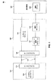
図1は、デジタルデバイス150及び周辺機器180に接続されたデジタルデータデバイスインタフェース100のブロック図である。デジタルデバイス150は、限定される訳ではないが、セルラ電話、パーソナルデータアシスタント、スマートフォン又はパーソナルコンピュータを含むことができる。一般に、デジタルデバイス150は、デジタル表示データの処理及びデジタル命令のための処理ユニットとして役立つ任意のタイプのデジタルデバイスを含むことができる。デジタルデバイス150は、システムコントローラ160及びリンクコントローラ170を含む。
FIG. 1 is a block diagram of a digital
周辺機器180は、限定される訳ではないが、カメラ、バーコードリーダ、イメージスキャナ、オーディオデバイス、またセンサを含むことができる。一般に、周辺機器180は、周辺機器と処理ユニットとの間でデジタル表示データを交換することができるオーディオ、ビデオ又はイメージキャプチャ、及びディスプレイデバイスのうちの任意のタイプを含みうる。周辺機器180は、制御ブロック190を含む。例えば、周辺機器180がカメラである場合、制御ブロック190は、限定される訳ではないが、レンズコントロール、フラッシュ又はホワイトLEDコントロール、及びシャッタコントロールを含むことができる。デジタル表示データは、オーディオ、イメージ、及びマルチメディアデータを表わすデジタルデータを含むことができる。
デジタルデータインタフェースデバイス100は、通信リンク105を介して、高レートで、デジタル表示データを転送する。一例では、毎秒3.2ギガビットの最大帯域幅で双方向データ転送をサポートするMDDI通信リンクが使用される。この例よりも高い又は低いレートであるその他の高レートデータ転送が、通信リンクに依存してサポートされうる。デジタルデータインタフェースデバイス100は、メッセージ解釈モジュール100、コンテンツモジュール120、制御モジュール130、及びリンクコントローラ140を含む。
The digital
デジタルデータインタフェース100内に配置されたリンクコントローラ140と、デジタルデバイス150内に配置されたリンクコントローラ170とは、通信リンク105を確立する。リンクコントローラ140及びリンクコントローラ170は、MDDIリンクコントローラでありうる。
A
本明細書において参照によってその全体が組み込まれるVESA(Video Electronics Standards Association)MDDI規格は、ポータブルデバイスに、小型のポータブルデバイスから大型の外部ディスプレイにデジタルイメージを伝送させる高速デジタルパケットインタフェースの要件を記載している。MDDIは、ポータブル計算デバイス、通信デバイス、及びエンタテイメントデバイスを、例えばウェアラブルマイクロディスプレイのような先端製品にリンクするために理想的な薄型フレキシブルケーブル及び小型コネクタシステムを適用する。それはまた、コストを低減し、かつ接続の信頼性を高めるために、ホストプロセッサとディスプレイデバイスとの間の接続をどのように簡素化するかに関する情報をも含む。リンクコントローラ140,170は、VESA MDDI規格に基づいて通信路105を確立する。
The Video Electronics Standards Association (VESA) MDDI standard, which is incorporated herein by reference in its entirety, describes the requirements for a high-speed digital packet interface that allows a portable device to transmit a digital image from a small portable device to a large external display. ing. MDDI applies an ideal thin flexible cable and miniature connector system for linking portable computing devices, communication devices, and entertainment devices to advanced products such as wearable microdisplays. It also includes information on how to simplify the connection between the host processor and the display device in order to reduce costs and increase the reliability of the connection. The
2004年7月6日にZouらに与えられ、Generating and Implementing a Communication Protocol and Interface for High Data Rate Signal Transfer(高速データレート信号伝送のための通信プロトコル及びインタフェースを生成し実施すること)と題された米国特許6,760,772号(’772特許)(特許文献1)は、表示データのための通信プロトコルを形成するためにともにリンクされたパケット構成を用いて、通信路を介してホストとクライアントとの間でデジタルデータを転送するためのデータインタフェースを記載している。前記’772特許で教示された発明の実施形態は、MDDIインタフェースに向けられる。信号プロトコルは、例えばリンクコントローラ140,170のようなリンクコントローラによって用いられ、通信プロトコルを構成するパケットを生成、送信、及び受信するように、かつデジタルデータを、少なくとも1つがホストデバイスに存在し、例えば通信路105のような通信路を介してクライアントに接続されている1又は複数タイプのデータパケットを形成するように構成されている。
Awarded to Zou et al. On July 6, 2004 and entitled Generating and Implementing a Communication Protocol and Interface for High Data Rate Signal Transfer. U.S. Pat. No. 6,760,772 (the '772 patent) (Patent Document 1) uses a packet structure linked together to form a communication protocol for display data, A data interface for transferring digital data to and from a client is described. The embodiment of the invention taught in the '772 patent is directed to the MDDI interface. The signaling protocol is used by link controllers, such as
このインタフェースは、コスト効率が良く、低電力で、双方向性の高速データ伝送メカニズムを、短距離「シリアル」タイプのデータリンクを介して提供する。これは、小型コネクタ及び薄型フレキシブルケーブルを用いた実装に向いている。リンクコントローラ140,170の実施形態は、’772特許の教示に基づいて通信路105を確立する。’772特許は、本明細書では、参照によって全体が組み入れられる。
This interface provides a cost-effective, low-power, bidirectional, high-speed data transmission mechanism over a short-range “serial” type data link. This is suitable for mounting using a small connector and a thin flexible cable. Embodiments of
他の実施形態では、リンクコントローラ140,170は、ともにUSBリンクコントローラになりえる。あるいはそれらはともに、例えばMDDIリンクコントローラのようなコントローラと、例えばUSBリンクコントローラのような別のタイプのリンクコントローラとの組み合わせを含みうる。あるいは、リンクコントローラ140,170は、例えばMDDIリンクコントローラのようなコントローラと、デジタルデータインタフェースデバイス100とデジタルデバイス150との間でアクノレッジメッセージを交換するためのシングルリンクとの組み合わせを含みうる。リンクコントローラ140,170は、更に、例えばイーサネット(登録商標)あるいはRS−232シリアルポートインタフェースのような別のタイプのインタフェースをサポートすることができる。本明細書での教示に基づいて、関連技術における個々の熟練者によって知られるように、更なるインタフェースもサポートされうる。
In other embodiments, the
デジタルデータインタフェースデバイス100内では、メッセージ解釈モジュール110が、通信リンク105を介してコマンドを受信し、システムコントローラ160への応答メッセージを生成する。更に、コマンドメッセージを解釈し、このコマンドの情報コンテンツを、デジタルデータインタフェースデバイス100内の適切なモジュールへ経路付ける。
Within digital
コンテンツモジュール120は、周辺機器180からデータを受信し、このデータを格納し、通信リンク105によってシステムコントローラ160にこのデータを転送する。
The
制御モジュール130は、メッセージ解釈モジュール130から情報を受け取り、この情報を、周辺機器180の制御ブロック190へ経路付ける。また制御モジュール130は、制御ブロック190からも情報を取得して、この情報を、メッセージ解釈モジュール110へ送ることができる。
The
図2は、上部クラムシェル部と下部クラムシェル部とを有するセルラ電話200のブロック図であり、上部クラムシェル部と下部クラムシェル部との間に配置されたコンポーネント間で高速データ通信を提供するためにMDDIインタフェースを用いている。セルラ電話200に関連する以下の記述は、例示的な例を提供し、デジタルデータインタフェースデバイス100の利用を示し、また、その実施及び用途に関連する更なる詳細を与える。この説明に基づいて、例えばパーソナルデジタルアシスタントのような他のデバイスや、他のタイプのモバイル電話とのデジタルデータインタフェース100の使用が明らかになるであろう。そして、それもまた本発明の精神及び範囲内である。
FIG. 2 is a block diagram of a
図2に示すように、セルラ電話200の下部クラムシェル部202は、モバイル局モデム(MSM:Mobile Station Modem)ベースバンドチップ204を含む。MSM204は、ディジタルベースバンドコントローラである。セルラ電話200の上部クラムシェル部214は、液晶ディスプレイ(LCD)モジュール216、及びカメラモジュール218を含んでいる。セルラ電話で一般に使用されているように、下部クラムシェル部202と上部クラムシェル部214はともに、プラスチックで覆われている。ヒンジ250,252は、下部クラムシェル202を上部クラムシェル214に機械的に接続する。フレキシブルカップリング254は、下部クラムシェル202と上部クラムシェル214との間の電気的な結合を提供する。
As shown in FIG. 2, the
MDDIリンク210は、MSM204にカメラモジュール218を接続する。一般に、MDDIリンクコントローラは、カメラモジュール218及びMSM204のそれぞれに対して提供される。セルラ電話200内では、例えば、MDDIホスト222が、カメラモジュール212に接続されたインタフェースシステム230に統合される。一方、MDDIクライアント206は、MDDIリンク210のMSM側に存在する。一般に、MDDIホストは、MDDIリンクのマスタコントローラである。
MDDI link 210 connects
セルラ電話200では、カメラモジュール218からピクセルデータが受信され、MDDIホスト222を用いてインタフェースシステム230によってMDDIパケットにフォーマットされ、その後、MDDIリンク210で送信される。MDDIクライアント206は、MDDIパケットを受信し、それらを、カメラモジュール218によって生成されたものと同じフォーマットのピクセルデータに再変換する。そして、ピクセルデータは、処理のために、MSM204内の適切なブロックに送られる。
In
同様に、MDDIリンク212は、MSM204にLCDモジュール216を接続する。MDDIリンク212は、MSM204に統合されたMDDIホスト208と、LCDモジュール216に接続されたインタフェースシステム232に統合されたMDDIクライアント220とを相互接続する。MSM204のグラフィックコントローラによって生成されたディスプレイデータは、MDDIホスト208によって受信され、そしてMDDIパケットにフォーマットされ、しかる後に、MDDIリンク212で送信される。MDDIクライアント220は、MDDIパケットを受信し、それらをディスプレイデータに再変換し、このディスプレイデータを、LCDモジュール216によって用いられるために、インタフェースシステム232によって処理する。
Similarly, the MDDI link 212 connects the
インタフェースステム230,232は、デジタルデータデバイスインタフェース100の異なる実施形態を表わす。インタフェースシステム230の場合には、デジタルデータデバイスインタフェース100要素は、カメラのためのカメラ制御機能、及びカメライメージのデータ転送をサポートするように実装されるであろう。インタフェースシステム232の場合には、デジタルデータデバイスインタフェース100要素は、LCDのための制御機能、及びLCDに対するデータ表示をサポートするように実装されるであろう。インタフェースシステム230は、例えばカメラモジュール218を備えたセルラ電話200のように、カメラを備えたセルラ電話において使用される場合、デジタルデータデバイスインタフェース100の実施形態を例示するために更に説明される。
Interface stems 230 and 232 represent different embodiments of digital
図1におけるデバイスと、セルラ電話200との間の関係は以下の通りである。デジタルデータデバイスインタフェース100は、インタフェースシステム230によって代表される。リンクコントローラ140は、MDDIホスト222によって代表される。周辺機器180は、カメラモジュール218によって代表される。システムコントローラ160は、MSM204によって代表され、リンクコントローラ170は、MDDIクライアント206によって代表される。
The relationship between the device in FIG. 1 and the
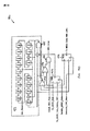
図3は、上部クラムシェル214のブロック図であり、カメラを備えたセルラ電話内で使用されるデジタルデータデバイスインタフェース100の実施形態を強調するために、インタフェースシステム230に関連する更なる詳細を提供する。インタフェースシステム230は、MDDIホスト222、カメラメッセージインタプリタ302、カメラビデオインタフェース304、I2Cマスタ303、モータ制御308、およびフラッシュ/白LEDタイマ310を含んでいる。I2Cバスは、回路間の通信リンクを提供する、一般に使用される制御バスである。I2Cバスは、1980年代にフィリップスエレクトロニクスN.V.によって開発された。
FIG. 3 is a block diagram of the
インタフェースシステム230が、デジタルデータデバイスインタフェース100に対応していることを思い出して頂きたい。インタフェースシステム230のコンポーネントは、以下のように、デジタルデータデバイスインタフェース100のコンポーネントに対応している。カメラメッセージインタプリタ302は、メッセージインタプリタモジュール100に対応している。カメラビデオインタフェース304は、コンテンツモジュール120に対応している。まとめると、I2Cマスタ303、モータ制御308、及びフラッシュ/白LEDタイマ310は、制御モジュール130に対応している。
Recall that
カメラメッセージインタプリタ302は、コマンドを受け取り、MDDIホスト222を介してMSM204へと応答メッセージを生成する。カメラメッセージインタプリタ302は、メッセージを解釈し、MDDIカメラインタフェースデバイスとも称されるインタフェースシステム230内の適切なブロックへ情報コンテンツを送る。カメラビデオインタフェース304は、カメラ320からイメージデータを受け取り、このイメージデータを格納し、このイメージデータをMDDIホスト222に転送する。まとめると、I2Cマスタ306、モータ制御308、及びフラッシュ/白LEDタイマ310は、カメラ制御ブロックを形成する。この場合、I2Cマスタ306は、カメラ320を管理するための制御を提供し、モータ制御308は、レンズ322を管理するための制御(例えば、レンズズーム機能)を提供し、フラッシュ/白LEDタイマ310は、フラッシュ/白LED324を管理するための制御(例えば、フラッシュ輝度及び持続時間)を提供する。
The
図4Aは、MDDIホスト222のブロック図である。MDDIホスト222は、マイクロプロセッサインタフェース410、コマンドプロセサ420、レジスタ430、ダイレクトメモリアクセス(DMA)インタフェース440、MDDIパケットビルダ450、データハンドシェークモジュール460、及びデータパッド470を含む。マイクロプロセッサインタフェース410は、バスを用いて、MDDIホスト222を制御するホストプロセッサにインタフェースする。ホストプロセッサは、レジスタを設定し、レジスタを読み取り、MDDIホスト222にコマンドを発行するためにマイクロプロセッサインタフェース410を用いる。マイクロプロセッサインタフェース410は、アドレス値を調べ、MDDIホスト222内の適切なモジュールへデータを渡す。これは、コマンドプロセッサ420への書き込みを渡すことを含む。更にマイクロプロセッサインタフェース410は、レジスタ430内のレジスタ値の読み取り及び書き込みを行う。
FIG. 4A is a block diagram of the
コマンドプロセッサ420は、ホストプロセッサから受け取ったコマンドを処理する。コマンドは、MDDIリンク210のパワーダウン、MDDIリンク210のパワーアップ、MDDIホスト222の再設定、あるタイプのデータパケットの生成を含む。
The
レジスタ430は、MDDIリンク210を介したデータ送信のためのレジスタを格納する。レジスタ430内のレジスタは、MDDIホスト222のコンフィグレーションと同様に、MDDIリンク210の挙動を制御する。
DMAインタフェース440は、外部メモリに対して、MDDIパケットビルダ450用のデータをバッファするためインタフェースシステム230からの情報を受信するように、バースト要求を与える。DMAインタフェース440は、リンクリストノードヘッダのデータを解析し、実際のパケットデータを読むためにポインタを調節する。DMAインタフェース440は、MDDIパケットビルダ450に送り出す次のデータパケットに関する情報を表示する。
The
MDDIパケットビルダ450は、MDDIリンク222に送る必要のある物理パケットを構築することと同様に、どのパケットを次に送るかに関する決定を行う。これらパケットは、内部レジスタ、カウンタ、及びDMAインタフェース440によって取得されたデータから構築される。データが、MDDIリンク222によって出力される場合、出力データは、いくつかのソースから生成されうる。第1のパケットソースは、MDDIパケットビルダ450に対して内部生成された制御タイプパケットである。パケットの例は、サブフレームヘッダパケット、フィルパケット、及びリンクシャットダウンパケットを含む。別のパケットソースは、DMAインタフェース440を介する。これらのパケットは、リンクされたリストを経由して渡されるパケットを含む。他の実施形態では、ビデオデータは、周辺機器がビデオカメラを含んでいる場合、MDDIパケットビルダ450に直接的に渡されうる。パケットソースに関わらず、全てのパケットは、MDDIパケットビルダ450内に存在するCRCジェネレータシステムを通じて処理される。
The
データハンドシェークモジュール460は、物理的MDDIリンク210を管理する。これは、ハンドシェーク処理、データ出力、往復遅延測定及び逆方向データに責任を持つ状態計算機を用いて遂行される。データハンドシェークモジュール460は、MDDIパケットビルダ450からデータを受け取り、このデータを、データパッド470に渡す。データパッド470は、このデータを、MDDIリンク222に転送する。
図4Bは、MDDIリンク210に提供されるパケットのフローを例示する。上述したように、パケットは、内部生成され、DMAインタフェース440から受け取られるか、あるいは直接的に受信されたビデオパケットである。内部生成されたパケットは、制御パケットジェネレータ452によって生成される。全てのタイプのパケットが、CRCジェネレータシステム454を介してデータハンドシェークモジュール460へ渡される。一方、データハンドシェークモジュール460は、データパッド470にパケットを提供する。データパッド470は、MDDIリンク210にこのデータを送る。
FIG. 4B illustrates the flow of packets provided on the
図4Cは、MDDIパケットビルダ450によって、MDDIリンク210を介して受信されるパケットのフローを例示する。この場合、パケットは、データパッド470によってMDDIリンク210から受信され、次に、データハンドシェークモジュール460に渡される。データハンドシェークモジュール460は、このデータを、MDDIパケットビルダ450内のCRCチェッカ456へ渡す。一旦CRCチェッカ456が、到来したパケットのCRCを確認すると、このパケットは、デジタルデータインタフェースデバイス100内での配信のため、プロセッサバスに送られるためにDMAインタフェース440に供給される。
FIG. 4C illustrates the flow of packets received by the
パケットタイプの例は、図5及び図6に関して記載される。これらパケットの例は、本発明を例示するために使用されるが、これらのパケットタイプのみに本発明を限定するように意図されない。以下に述べるように、ユニークパターンを用いたその他のパケットタイプ、及びCRCフィールドを、本発明とともに使用することができる。 Examples of packet types are described with respect to FIGS. These packet examples are used to illustrate the invention, but are not intended to limit the invention to only these packet types. As described below, other packet types with unique patterns and CRC fields can be used with the present invention.
図5は、VESA MDDIインタフェース規格に従ったサブフレームヘッダパケットフォーマット500のブロック図である。サブフレームヘッダパケットフォーマット500は、パケット長フィールド510、パケットタイプ長フィールド520、ユニークワードフィールド530、サブフレームヘッダパラメータフィールド540、及びCRCフィールド550を含む。パケット長フィールド510は、パケット長フィールド510を含まないパケット内の合計バイト数を指定する16ビット(2バイト)値を含む。パケットタイプフィールド520は、パケットに含まれる情報のタイプを指定する16ビットの無符号整数を含む。ユニークワードフィールド530は、ユニークな16ビットワードを含む。ユニークワードフィールド及びパケットタイプフィールド520の両方は、データを並べるための32ビットのユニークパターンを形成するものと認識される。すなわち、パケットを受信した場合、MDDIパケットビルダ450は、このユニークパターンに基づいて、MDDIパケットビルダ450が処理しているのが、データパケットのどの部位又はフィールドであるかを判定することができる。サブフレームヘッダパラメータフィールド540は、MDDIリンク222を管理するための制御パラメータを含んでいる。CRCフィールドは、16ビットのCRC値を含んでいる。
FIG. 5 is a block diagram of a subframe
図6は、ビデオストリームパケットフォーマット600のブロック図である。ビデオストリームパケットは、ディスプレイの長方形部分を更新するためにビデオデータを運ぶ。ビデオストリームパケットフォーマット600は、パケット長フィールド610、パケットタイプフィールド615、クライアントIDフィールド620、ビデオフォーマットフィールド625、ピクセルデータ属性フィールド630、X左端フィールド635、Y上端フィールド640、X右端フィールド645、Y下端フィールド650、X開始フィールド655、Y開始フィールド660、ピクセルカウントフィールド665、パラメータCRCフィールド670、ピクセルデータフィールド675、及びピクセルデータCRCフィールド680を含む。
FIG. 6 is a block diagram of a video
パケット長フィールド610は、パケット長フィールド610を含まないパケット内の合計バイト数を指定する16ビット(2バイト)値を含んでいる。パケットタイプフィールド620は、パケットに含まれている情報のタイプを指定する2バイトの無符号整数を含んでいる。
The packet length field 610 includes a 16-bit (2 byte) value that specifies the total number of bytes in the packet that does not include the packet length field 610. The
フィールド620乃至665はそれぞれ、ビデオディスプレイがどのようにフォーマットされるかに関するパラメータデータを含む2バイトのフィールドである。これらフィールドの具体的定義は、VESA MDDIインタフェース規格において見つけることができる。パラメータCRCフィールド670は、フィールド610乃至665内のパラメータデータを処理することにより生成されるCRC値を含む2バイトのフィールドである。
ピクセルデータフィールド675は、パケットサイズ及びピクセルカウントフィールドで許可された量までの任意のピクセルデータ量を含む。ピクセルCRCフィールド680は、ピクセルデータフィールド675内でピクセルデータを処理することによって生成されるCRC値を含む2バイトフィールドである。
The
MDDIリンク210によって送られる全てのパケットは、サブフレームヘッダパケットフォーマット500内のCRCフィールド550のような少なくとも1つのCRCフィールドを含む。幾つかのより長いパケットでは、パケットは、例えばパラメータCRCフィールド670とピクセルCRCフィールド680とのように、ビデオストリームパケットフォーマット600内に2つのCRCフィールドを含むであろう。
All packets sent by MDDI link 210 include at least one CRC field, such as
CRCは、送信又は格納における誤りを検出するために、例えばネットワークトラフィックパケット、又はコンピュータファイルのブロックのような大きなデータブロックから多くの小さなビットを生成する。CRCは、(例えばCRCフィールド550とともに)送信又は格納前に送られ追加されるデータの関数として計算され、その後、変化が起きていないことを確認するために検証される。 The CRC generates many small bits from large blocks of data, such as network traffic packets or blocks of computer files, to detect errors in transmission or storage. The CRC is calculated as a function of the data sent and added before transmission or storage (eg, with the CRC field 550) and then verified to confirm that no change has occurred.
CRCは、パケットデータを、例えばCRCジェネレータシステム454のようなCRCジェネレータを介してプッシュすることによって計算され、パケットデータに関連するユニークなCRC値が生成される。CRCチェッカ456のようなCRCチェッカは、受信データに基づいて、受信データCRC値を生成する。そして、この受信データCRC値は、送られたCRC値と比較される。これら2つが一致すると、データは有効であると考えられ、一致しないと、CRC誤りが生成される。
The CRC is calculated by pushing the packet data through a CRC generator, such as
CRCは一般的である。なぜなら、バイナリハードウェア内で実施することが簡単であり、数学的に分析することが容易であり、送信チャネル内の雑音によって引き起こされる一般的な誤りを検出することに特に優れているからである。CRCジェネレータの具体的な実装は、関連技術における個々の熟練者に知られるであろう。 CRC is common. Because it is simple to implement in binary hardware, easy to analyze mathematically, and is particularly good at detecting common errors caused by noise in the transmission channel . The specific implementation of the CRC generator will be known to the individual skilled in the relevant art.
図5及び図6に例示するように、CRCフィールドは、パケット内において、パケットの終わり(例えば、CRCフィールド512及びピクセルデータCRCフィールド680)において、及び時々、著しく大きなデータフィールド(例えば、パラメータCRCフィールド670)をもつより重要なパラメータの後に現れる。従って、転送中の誤りの確率が増加する。2つのCRCフィールドを持っているパケットでは、1つのみが使用される場合、CRCジェネレータが、最初のCRC後に再び初期化される。これによって、長いデータフィールド後のCRC計算が、パケットの最初におけるパラメータによって影響されなくなる。 As illustrated in FIGS. 5 and 6, the CRC field is within the packet, at the end of the packet (eg, CRC field 512 and pixel data CRC field 680), and sometimes significantly larger data fields (eg, parameter CRC field). 670) appears after the more important parameters. Therefore, the probability of errors during transfer increases. For packets with two CRC fields, if only one is used, the CRC generator is reinitialized after the first CRC. This makes CRC calculations after long data fields unaffected by parameters at the beginning of the packet.
多くのビット誤りを含むパケットの可能性が低くなり、良好なCRCを生成する。パケットにおける良好なCRCを、誤って検出する確率は、多くの誤りを含む非常に長いパケットについて、7.6×10⁻⁶に近づく。設計によって、MDDIリンクは、非常に低いか、ゼロの誤り率を持つであろう。CRCは、リンクの健全性をモニタするために使用されることが意図され、どのパケットが再送信されるべきかを決定するために具体的パケットに関する誤りを検出することは意図されていない。 The likelihood of a packet containing many bit errors is reduced, producing a good CRC. The probability of erroneously detecting a good CRC in a packet approaches 7.6 × 10 −6 for very long packets that contain many errors. Depending on the design, MDDI links will have very low or zero error rates. The CRC is intended to be used to monitor link health and is not intended to detect errors on specific packets to determine which packets should be retransmitted.
典型的な実施形態では、CRC計算に使用される多項式は、CRC−16、すなわちX16+X15+X2+X0として知られている。本発明を実現するために役立つCRCジェネレータ454及びCRCチェッカ456のサンプル実装が図4Dに示される。図4Dでは、Tx_MDDI_Data_Before_CRCラインに入力されたパケットの最初のビットを転送する直前に、CRCレジスタ471が、値0x0001に初期化され、次に、このパケットのバイトが、LSBから始まるレジスタ内にシフトされる。この図中のレジスタビット番号は、MDDIによって使用されるビット位置ではなく、使用される多項式の順序に対応することに留意されたい。単一方向にCRCレジスタをシフトするのがより効率的であり、その結果、MDDIビット位置14に到達するまで、CRCビット15は、MDDI CRCフィールドのビット位置0に、CRCレジスタビット14は、MDDI CRCフィールドビット位置1というように現れる。
In an exemplary embodiment, the polynomial used for CRC calculation is known as CRC-16, ie X16 + X15 + X2 + X0. A sample implementation of a
一例として、パケットコンテンツが、0x000c、0x0046、0x000、0x0400、0x00、0x00、0x0000であり(あるいは、0x0c、0x00、0x46、0x00、0x00、0x00、0x00、0x04、0x00、0x00、0x00、0x00のようにバイトのシーケンスとして表され)、マルチプレクサ472,473及びANDゲート474の入力を用いて出力されるのであれば、結果としてTx_MDDI_Data_With_CRCライン上で得られるCRC出力は、0xd9aaである(あるいは0xaa,0xd9としてシーケンスで表される)。
As an example, the packet contents are 0x000c, 0x0046, 0x000, 0x0400, 0x00, 0x00, 0x0000 (or 0x0c, 0x00, 0x46, 0x00, 0x00, 0x00, 0x00, 0x04, 0x00, 0x00, 0x00, 0x00, etc. And the resulting CRC output on the Tx_MDDI_Data_With_CRC line is 0xd9aa (or as 0xaa, 0xd9), if output using the inputs of
CRCジェネレータ454とCRCチェッカ456がCRCチェッカとして構成される場合、Rx_MDDI_Dataライン上で受信されるCRCは、マルチプレクサ472及び排他的OR(XOR)ゲート476に入力され、NORゲート475、ANDゲート474、及びANDゲート477を用いてCRCレジスタにおいて発見される値と、ビット毎に比較される。誤りがある場合、ANDゲート477による出力として、ゲート477の出力をレジスタ471の入力に接続することによって、CRC誤りを含むパケットについて一度づつCRCがインクリメントされる。図4Dのブロック図内に示す回路の例は、与えられたCHECK_CRC_NOWウィンドウ(図4E参照)内で、1よりも多いCRC誤り信号を出力できることに留意されたい。従って、CRC誤りカウンタは、一般に、CHECK_CRC_NOWがアクティブである各インターバル内で最初のCRC誤りインスタンスのみをカウントする。CRCジェネレータとして構成される場合、CRCは、パケットの終了と一致する時間においてCRCレジスタから計時される。
If
入出力信号及びイネーブル信号のタイミングは、図4E及び図4Fにおいてグラフ的に例示される。CRCの生成、及びデータパケットの送信は、Tx_MDDI_Data_Before_CRC信号及びTx_MDDI_Data_With__CRC信号とともに、Gen_Reset信号、Check_CRC_Now信号、Generate_CRC_Now信号、及びSending_MDDI_Data信号の状態(0又は1)を示す図4Eに示される。データのパケットの受信、及びCRC値のチェックは、Rx MDDI Data信号及びCRC error信号とともに、Gen_Reset信号、Check_CRC_Now信号、Generate_CRC_Now信号、及びSending_MDDI_Data信号の状態を示す図4Fに示される。 The timing of the input / output signals and the enable signal is illustrated graphically in FIGS. 4E and 4F. CRC generation and data packet transmission are shown in FIG. 4E showing the states (0 or 1) of the Gen_Reset signal, Check_CRC_Now signal, Generate_CRC_Now signal, and Sending_MDDI_Data signal together with the Tx_MDDI_Data_Before_CRC signal and the Tx_MDDI_Data_With__CRC signal. The reception of the data packet and the CRC value check are shown in FIG. 4F showing the states of the Gen_Reset signal, Check_CRC_Now signal, Generate_CRC_Now signal, and Sending_MDDI_Data signal together with the Rx MDDI Data signal and the CRC error signal.
パケット内にCRCが存在することは、運用上のチャレンジを示し、また、MDDIリンク210をより効率的に利用するための様々な機会を与える余裕がある。CRCに関する議論の焦点は、MDDIリンク210に関連しているが、本発明は、MDDIコンテンツに限定されない。本発明は、CRCが使用される任意のタイプのデジタルデータ送信リンクに適用されうる。 The presence of a CRC in the packet represents an operational challenge and can afford various opportunities to use the MDDI link 210 more efficiently. Although the focus of the discussion regarding CRC is related to MDDI link 210, the present invention is not limited to MDDI content. The present invention can be applied to any type of digital data transmission link where CRC is used.
CRCの使用に関連した1つのチャレンジは、リンク初期化に関連する。リンクが確立すると、サブフレームヘッダパケット500のようなサブフレームヘッダパケットが、MDDIホスト222によってMDDIクライアント206へ送られる。リンク初期化時、CRCチェッカ456は、通常、データストリーム内のデータの並びが分からないであろう。すなわち、例えば、CRCチェッカ456は、それがユニークワードフィールド530内の処理データであるか、あるいはCRCフィールド550内の処理データであるか分からないであろう。その結果、CRCチェッカ456は、データストリーム内のどこにあるかを認識するまで、データをメモリに連続的にキューする必要はないであろう。これは、非能率をもたらし、データをキュー及び格納するために使用されるよりも多くのメモリとチップ領域とを必要とする。データストリーム内の正確な位置を知らずに、CRCチェッカ456は、受信データを検証するために受信CRCと比較されるCRCを生成することはできないであろう。
One challenge associated with using CRC is related to link initialization. When the link is established, a subframe header packet, such as
図7は、これらのチャレンジに対処するCRCチェッカ456のブロック図である。CRCチェッカ456は、ユニークパターン検出器710、CRCジェネレータ720、CRCイニシャライザ730、及びCRCベリファイヤ740を含む。ユニークパターン検出器710は、到来するデータストリーム内のユニークなパターンを検出し、このデータストリーム内の特定のポイントを識別する。CRCジェネレータ720は、受信データに関連するCRC値を生成するために使用される標準的なCRCジェネレータである。CRCイニシャライザ730は、CRCジェネレータ720に、ユニークパターン及びパケット長に関連するデータ値を送る。CRCベリファイヤ740は、受信データを確認するために、受信CRC値を、受信データに基づいてCRCジェネレータ720によって生成されたCRC値と比較する。
FIG. 7 is a block diagram of a
図8は、リンク初期化方法800のフローチャートであり、図7に示すようなCRCチェッカ456の使用を実証する。1つのアプローチでは、サブフレームヘッダのパケット長が、常に同一であると仮定され、予め計算された値が、CRCチェッカにロードされる。これは、パケット長、パケットタイプ、及びユニークワードに基づく部分的なCRCである。代替アプローチは、パケット長さが変数である状況をサポートする。この状況では、パケット長が、ユニークパターンとともに、事前計算機を介して送られ、値が生成される。この値は、ユニークパターンが受信された時、このポイントにおいてCRCチェッカ内に配置される。
FIG. 8 is a flow chart of a
方法800はステップ810で始まる。ステップ810では、送信リンクを初期化又はウェイクアップする要求が受信される。例えば、MDDIクライアント206は、MDDIリンク210を初期化又はウェイクアップする要求を、MDDIホスト222から受信するだろう。MDDIクライアント206内では、CRCチェッカ456は、このリンクウェイクアップ要求によって初期化されうる。特に、CRCイニシャライザ730は、この要求によって初期化されうる。
ステップ820では、CRCジェネレータが、ユニークパターン及びパケット長フィールド510に関連するデータ値が予め入力され、ユニークパターン及びパケット長フィールドに関連するCRC値が、CRCジェネレータによって生成される。上述したように、1つの実施形態では、パケット長フィールドは、固定されていると仮定される。例えば、CRCイニシャライザ730は、ユニークパターン及びパケット長フィールドをCRCジェネレータ720に提供することができる。MDDIの場合、このユニークパターンは、パケットタイプフィールド520及びユニークワードフィールド530内に含まれるデータに関連するデータ値である。リンクをウェイクアップすると、これらフィールドの値が、演繹的に知られるだろう。従って、CRCイニシャライザ730は、それらを格納し、ウェイクアップリンク要求が受信された場合にそれらをCRCジェネレータ730に提供する立場にある。代替アプローチでは、CRCジェネレータにデータ値を提供するのではなく、CRCチェッカは、提供されたユニークパターン及びパケット長フィールドを有するCRCジェネレータによって生成され、事前に計算されたCRC値とともに事前にロードされる。
In
ステップ830では、例えばCRCジェネレータ720のようなCRCジェネレータがディセーブルされる。このジェネレータは、更なるデータを処理してCRC値を変更しないように、ユニークパターン及びパケット長フィールドが受信されるまでディセーブルされる。
In step 830, a CRC generator, such as
ステップ840では、到来するデータがモニタされ、ユニークデータパターンの受信が確認される。例えば、ユニークパターン検出器710は、MDDIリンク210からの受信データをモニタする。
In step 840, the incoming data is monitored to confirm receipt of the unique data pattern. For example, the
ステップ850では、ユニークパターンが受信されたことが判定される。例えば、ユニークパターン検出器710は、パケット長フィールド510、パケットタイプフィールド520、及びユニークワードフィールド530が受信されたことを判定する。
In
ステップ860では。CRCジェネレータがイネーブルされる。CRCジェネレータ720は、イネーブルされると、事前にロードされたユニークパターンを用いて生成された既存のCRC値に頼るであろう。その結果、CRCジェネレータ720は、データが直ちに並べられ、メモリ内にデータをキューして格納する必要はない。CRCフィールド550に含まれるCRC値を受け取ると、CRCベリファイヤ740は、CRCフィールド550内の値を、CRCジェネレータ720によって生成された値と比較して、CRC誤りが存在するかを判定する。ステップ870では、方法800が終了する。
In
通常、CRC値は、送信リンクに関する問題が、送信中のデータを破壊したかを判定するために使用される。本発明の別の局面では、CRC値は、システムエラー及びステータスに関連する情報を伝えるために使用される。このように、メッセージ内のCRCフィールドは、送信リンク問題と、システムステータス又は誤り情報との両方をサポートするためにより効率的に使用される。 Typically, the CRC value is used to determine if a problem with the transmission link has destroyed the data being transmitted. In another aspect of the invention, CRC values are used to convey information related to system errors and status. Thus, the CRC field in the message is used more efficiently to support both transmission link problems and system status or error information.
本発明の1つの実施形態では、CRCフィールドデータが破壊され、データを送信しているシステムに何か不具合があり、受信中のデータに問題があるかもしれないことが単に示される。例えば、ある場合には、MDDIリンク210を通って進むデータは、破壊されるであろう。なぜなら、MDDIパケットビルダ450に入るデータは、十分速く受信されないからである。たとえ不十分なデータがパケットに利用可能だったとしても、MDDI仕様は、パケットが依然として送られるべきであると記載している。従って、たとえパケットが送られても、データは有効ではないか、あるいは幾分不十分でありうる。
In one embodiment of the present invention, CRC field data is corrupted and it is simply indicated that there may be something wrong with the system sending the data and there may be a problem with the data being received. For example, in some cases, data traveling through the MDDI link 210 will be destroyed. This is because the data entering the
この場合、例えばパラメータCRC670又はピクセルデータ680のようなCRC値が故意に破壊され、MDDIクライアント206は、送信されたパケットの完全性を害する何かが起こったことを認識できるようになる。MDDI仕様では、これが、データに問題があることをMDDIクライアント206に通知する方法である。あるいは、誤りを含むパケットの後に、基本的には「私が最後に送ったパケットは不完全である」と言う別のメッセージが送られる必要がある。
In this case, a CRC value, such as
MDDIクライアント206は、CRC値が故意に破壊されたパケットを受信すると、このパケットをどのように取り扱うか判断する。アルゴリズムは、故意に破壊されたCRC値を有するパケットを検出し、それをどのようにして取り扱うかを決定するように開発される。あるタイプのパケットについては、MDDIクライアント206は、単に、CRC誤りを記録し、データを使用し続けるかもしれない。一方、他の状況では、MDDIクライアント206は、受信パケットを廃棄し、新しいパケットを要求するかもしれない。
When the
例えば、ビデオストリームパケット600のようなビデオパケット内では、ピクセルデータCRC値680が故意に破壊された場合、MDDIクライアント220は、MDDIクライアント220の外部のロジックに、パケットが破壊されていることを通知しないであろう。この場合、受信データは、あらゆる種類の誤り通知を提供する前に、バッファされうる。ビデオデータの全て(すなわち、表示される全てのピクセルデータ)を潜在的にバッファする十分なメモリは存在しない。従って、ピクセルデータは、受信されるとすぐに、ディスプレイに供給される。その結果、ビデオ情報のどこかにCRC誤りがある場合、ビデオ情報の使用を停止するのには遅すぎる。この場合、問題が生じたと記録すること以外に何もなされない。要約すると、故意に破壊されたCRC誤りが、ピクセルデータ内で生じるが、パラメータデータ内には生じないのであれば、MDDIクライアントは、単に、このCRC誤りをエラーカウンタに記録するが、依然として次のピクセルデータを使用する。一方、パラメータCRC値が故意に破壊された場合、MDDIクライアントは、このピクセルデータを使用しないであろう。
For example, in a video packet such as
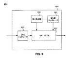
図9は、CRC値を故意に破壊するメカニズムを提供する巡回冗長ジェネレータシステム454のブロック図である。巡回冗長ジェネレータシステム454は、CRCジェネレータ910、CRCコラプタ920、誤り検出器930、及び誤り値ジェネレータ940を含む。
FIG. 9 is a block diagram of a cyclic
CRCジェネレータ910は、例えば、限定される訳ではないが、MDDIリンク210のようなデジタル送信リンクによって送信されるデータパケットに含まれるデータに基づいてCRC値を生成する。
The
CRCコラプタ920は、ホスト又は遠隔システムステータス情報を運ぶために、CRCジェネレータ910によって生成されたCRC値を破壊する。例えば、インタフェースシステム230が、適切にMDDIパケットを入力するためにMDDIホスト222に十分早くデータを提供できない場合、CRCコラプタ920は、送られたパケットのCRC値を故意に破壊する。
誤り検出器930は、例えばMDDIホスト222のようなホストシステム内で誤り条件を検出するか、あるいはインタフェースシステム230から受信した情報に基づいて誤り条件情報を受信し、CRCコラプタ920が、CRC値を故意に破壊するような指示を与える。1つの実施形態では、誤り検出器930は、単に、どこかに不具合があることを検出するが、具体的な誤り条件を判定しない。別の実施形態では、誤り検出器930は、誤り条件の特定のタイプを判定する。後者の実施形態では、誤り検出器930は、誤り値ジェネレータ940に誤りの特徴を伝える。誤り値ジェネレータ940は、CRCコラプタ940に対して、CRCジェネレータ940によって生成されたCRC値を、システムエラー又はステータス条件のタイプを示す具体的な値と交換するように命じる。
The
CRC値を破壊する場合、アルゴリズムは、故意に破壊することが、有効なデータに対応しうるCRC値に至らず、もって、送信リンクの受信端において、CRCチェッカによってユニークなCRC値として受信されないことを保証するようにアルゴリズムが選択されねばならない。1つの可能なアルゴリズムは、有効なデータによって生成されないCRC値を識別し、かつこれらの値を、CRC値を故意に破壊するためのユニークな値として使用することであろう。本明細書の教示に基づいて、関連技術における個々の熟練者は、本発明の精神及び範囲内に含まれる他のアルゴリズムを決定するであろう。 When destroying a CRC value, the algorithm shall not deliberately destroy the CRC value that can correspond to valid data and therefore not be received as a unique CRC value by the CRC checker at the receiving end of the transmission link. The algorithm must be selected to guarantee One possible algorithm would be to identify CRC values that are not generated by valid data, and use these values as unique values to deliberately destroy the CRC values. Based on the teachings herein, one of ordinary skill in the relevant art will determine other algorithms that fall within the spirit and scope of the invention.
図10は、CRCジェネレータシステム454からの故意に破壊されたCRC値を解釈することができるCRCチェッカ456のブロック図である。CRCチェッカ456は、CRC誤り値検出器1010、CRCジェネレータ1020、及びCRCベリファイヤ1030を含む。CRC誤り値検出器1010は、デジタル送信リンクによって受信されたデータパケットのCRCフィールド内の値を検出する。CRC誤り値検出器1010は、CRC値が、システムエラー条件を識別する故意に破壊されたCRC値に一致する場合を識別する。CRC値が、システムエラー条件に一致すると判定された場合、CRC誤り値検出器1010は、ホストプロセッサに、例えばMDDIクライアント206のような受信クライアントを通知する。ホストプロセッサは、検出された誤りのタイプに基づいて動作を講じるであろう。CRCジェネレータ1020は、受信されたデータストリームに基づいてCRC値を生成する。CRCベリファイヤ1030は、受信されたデータストリームに基づいて生成されたCRC値の、受信されたデータストリーム内で送られたCRC値に対する相違を検出する。CRCジェネレータ1020及びCRCベリファイヤ1030は、関連技術における個々の熟練者によって知られる従来方式で動作する。
FIG. 10 is a block diagram of a
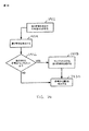
図11は、CRC値を故意に破壊することによって、デジタル送信リンクを介してシステムエラー情報を送信する方法1100のフローチャートである。方法1100は、ステップ1110で始まる。ステップ1110では、ホストシステムあるいは関連システム内で誤りが検出される。例えば、誤り検出器930は、MDDIホスト222あるいはインタフェースシステム230内で誤りを検出する。ステップ1120では、CRC値が生成される。例えば、CRCジェネレータ910は、送られるパケットに関連したデータに対してCRC値を生成する。ステップ1130では、CRC値が破壊される。例えば、誤り検出器930は、CRC値を破壊するようにCRCコラプタ920に命じる。ステップ1140で、方法1100は終了する。方法1100は、MDDIを含むシステムに関して記述されているが、方法1100は、CRCが使用されるあらゆるデジタル通信システムに適用可能であることに留意されたい。
FIG. 11 is a flowchart of a
本発明では、CRCフィールドは、誤りのタイプを表わす誤り符号情報を送信するために使用されてもよい。データパケットとCRCのみがホストとクライアントとの間で転送されている場合は常に、誤り符号は提供されていない。唯一の誤りは同期の損失である。そうでない場合、良好なデータ転送経路又はパイプラインの欠如によりリンクがタイムアウトになることを待ち、リンクをリセットし、続けなければならない。あいにく、これは、時間を浪費し、幾分非能率的である。 In the present invention, the CRC field may be used to transmit error code information representing the type of error. When only data packets and CRC are transferred between the host and client, no error code is provided. The only error is loss of synchronization. Otherwise, wait for the link to time out due to lack of a good data transfer path or pipeline, reset the link and continue. Unfortunately, this is time consuming and somewhat inefficient.
1つの実施形態での使用のために、新しい技術が開発された。そこでは、パケットのCRC部が、誤り符号情報を転送するために使用される。すなわち、1又は複数の誤り符号が、データ転送を取り扱うプロセッサ又はデバイスによって生成される。これは、通信処理又はリンク内で発生しうる特定の予め定義された誤り又は欠陥を示す。誤りに遭遇する場合、適切な誤り符号が生成され、パケットのCRCのビットを用いて転送される。すなわち、所望の誤り符号を用いてCRC値がオーバロード又はオーバライトされる。これは、CRCフィールドの値をモニタする誤りモニタ又はチェッカによって受信端上で検出される。幾つかの理由で、誤り符号がCRC値と一致する場合、混乱を避けるために、誤りのコンプリメントが転送される。 A new technology has been developed for use in one embodiment. There, the CRC part of the packet is used to transfer the error code information. That is, one or more error codes are generated by a processor or device that handles data transfer. This indicates certain predefined errors or defects that may occur in the communication process or link. If an error is encountered, an appropriate error code is generated and transferred using the CRC bits of the packet. That is, the CRC value is overloaded or overwritten using the desired error code. This is detected on the receiving end by an error monitor or checker that monitors the value of the CRC field. If for some reason the error code matches the CRC value, an error complement is transferred to avoid confusion.
1つの実施形態では、ロバストな誤り警告及び検出システムを提供するために、誤り符号は、一般に全てである一連のパケットを用いて、数回転送される。これは、誤りが検出された後に転送又は送信される。これは、誤りを生成する条件が、システムから取り除かれるポイントまで生じる。このポイントでは、規則的なCRCビットが、別の値によってオーバロードされることなく転送される。 In one embodiment, to provide a robust error warning and detection system, error codes are transferred several times using a series of packets that are generally all. This is transferred or transmitted after an error is detected. This occurs up to the point where the condition that generates the error is removed from the system. At this point, regular CRC bits are transferred without being overloaded by another value.
CRC値をオーバロードするこの技術は、最小量の追加ビット又はフィールドを用いながら、より迅速な応答をシステムエラーに提供する。 This technique of overloading the CRC value provides a faster response to system errors while using a minimal amount of additional bits or fields.
図12に示すように、CRCオーバライトメカニズム又は装置1200が、例えば誤り検出器930のような誤り検出器又は検出手段1202を用いて示されている。これは、以前に説明したか、あるいは周知の他の回路の一部を形成することができ、通信リンク又はプロセス内の誤りの存在又は実在を検出する。例えば誤り値ジェネレータ940のように、他の回路の一部として構成されることができるか、あるいは、例えば予め選択されたエラーメッセージを格納するためのルックアップテーブルのような技術を使用する誤り符号ジェネレータ又は手段1204は、特定の予め定めた誤りであるか、あるいは引き起こったものとして検出された欠陥を示すために1又は複数の誤り符合を生成する。デバイス1202,1204は、単一の回路又は所望されるデバイスとして、あるいは、他の周知のプロセッサ及び素子のためにプログラムされたステップのシーケンスの一部として形成することができることが容易に理解される。
As shown in FIG. 12, a CRC overwriting mechanism or
例えばCRCベリファイヤ1030のように、選択された誤り符号が、転送されたCRC値と同じであるかを確認するCRC値コンパレータ又は比較手段1206が示されている。その場合、オリジナルのCRCパターン又は値として誤解され、検出スキームを混乱させたり、又は複雑にすることがないように、符号コンプリメントジェネレータ又は生成手段又はデバイスが、誤り符合のコンプリメントを提供するために使用される。誤り符合セレクタ又は選択手段要素又はデバイス1210は、その後、挿入又はオーバライトが望まれる誤り符合又は値、あるいは適切なコンプリメントを選択する。例えばCRCコラプタ920のような誤り符合CRCオーバライタ、又はオーバライトメカニズム、又は手段1212は、所望の誤り符号を受信デバイスへ転送するために、データストリーム、パケット、及び挿入される所望の符号を受信し、対応するCRC値又は適切なCRC値をオーバライトするデバイスである。
A CRC value comparator or comparison means 1206 is shown, such as a
既に述べたように、誤り符合は、一連のパケットを用いて何度も転送されるので、オーバライタ1212は、処理中、符号のコピーを保持するために、あるいは、必要に応じて又は所望に応じて値を記憶又は保持するために使用することが可能な前の素子又は他の周知の記憶場所から符号を呼び戻すために、メモリ記憶素子を利用しうる。
As already mentioned, the error code is transferred many times using a series of packets so that the
図12のオーバライトメカニズムの一般的な処理の追加詳細が、図13及び図14に示されるように実施される。図13では、ステップ1302において、通信データ又はプロセスにおいて、1又は複数の誤りが検出され、ステップ1304において、誤り符号が選択され、この条件が示される。ステップ1306では、それと同時に、あるいは適切なポイントにおいて、交換されるCRC値がチェックされ、ステップ1308において、所望の誤り符号と比較される。この比較の結果は、以前説明したように、所望の符号、あるいはその他の代表値が、現在のCRC値と同じであるか否かの判定である。この場合、処理はステップ1312に進む。ここでは、コンプリメント、又は幾つかの場合には、所望に応じてその他の代表値が、挿入される符号として選択される。ステップ1310及び1314では、どの誤り符合又は値が挿入されるべきかが決定されると、その適切な符号が、挿入のために選択される。これらのステップは、明瞭さの目的のために個別に例示されているが、一般に、ステップ1308の判定に基づく単一の選択を表す。最後に、ステップ1316において、この処理のターゲットとされているパケットを用いて転送するために、適切な値がCRC位置にオーバライトされる。
Additional details of the general processing of the overwrite mechanism of FIG. 12 are implemented as shown in FIGS. In FIG. 13, in
パケット受信側では、図14に示すように、パケットCRC値が、ステップ1422においてモニタされる。一般に、CRC値は、データ転送中に誤りが発生したか、パケットの再送信を要求するか否かを判定するために、あるいは上述したもののうちの幾つかのような更なる動作を禁止するために、システム内で、1又は複数の処理とともにモニタされている。そのようなモニタリングの一部として、この情報はまた、値を、既知又は予め選択された誤り符号、あるいは代表値と比較し、誤りの存在を検出するためにも使用される。あるいは、個別の誤り検出処理およびモニタを実施することができる。符号が存在するように思われる場合、ステップ1424では、更なる処理のために抽出されるか、そうでない場合には注釈が付けられる。ステップ1426では、これが実際の符号であるか、あるいはコンプリメントであるかの判定がなされる。コンプリメントである場合には、追加ステップ1428が使用され、この値が、所望の符号値に変換される。何れの場合も、ステップ1430では、結果として抽出された符合、コンプリメント、又はその他の復元された値は、送信された符号から、どの誤りが生じたのかを検出するために使用される。
On the packet receiving side, the packet CRC value is monitored in
(結論)
本発明の典型的な実施形態が示された。本発明は、これらの例に限定されない。これらの例は、本明細書において、例示目的で表されており、限定のために表されているのではない。本明細書に含まれる教示に基づいて、代替例(本明細書の記載の等価物、拡張、変形、変更等)が、関連技術における熟練者に明らかになるであろう。そのような代替例は、本発明の範囲及び精神内にある。
(Conclusion)
An exemplary embodiment of the present invention has been shown. The present invention is not limited to these examples. These examples are presented herein for purposes of illustration and not for purposes of limitation. Based on the teachings contained herein, alternatives (equivalents, extensions, variations, modifications, etc., described herein) will become apparent to those skilled in the relevant art. Such alternatives are within the scope and spirit of the present invention.
本明細書で述べられた全ての出版物、特許、及び特許出願は、本発明が関連する技術における熟練者の熟練レベルを示しており、あたかも個々の出版物、特許、又は特許出願が、参照によって特別に及び個別に組み込まれていることが示されているかのように、同程度に参照によって本明細書に組み込まれている。 All publications, patents, and patent applications mentioned in this specification are indicative of the level of skill of those skilled in the art to which this invention pertains, as if each publication, patent or patent application was referenced. Are hereby incorporated by reference to the same extent as if otherwise specifically and individually indicated.
Claims (4)
デジタル送信リンクによって受信したデータストリーム内のユニークパターンを検出するユニークパターン検出器と、
前記受信したデータストリームに基づいてCRC値を生成するCRCジェネレータと、
リンクが初期化されると、前記CRCジェネレータに、前記ユニークパターンに関連するCRC値を事前入力するCRCイニシャライザと、
受信したデータストリームに基づいて生成されたCRC値の、前記受信したデータストリーム内で送られたCRC値に対する相違を検出するCRCベリファイヤと
を備えるCRCチェッカ。A cyclic redundancy check (CRC) checker,
A unique pattern detector for detecting a unique pattern in a data stream received by a digital transmission link;
A CRC generator for generating a CRC value based on the received data stream;
A CRC initializer that pre-populates the CRC generator with a CRC value associated with the unique pattern when a link is initialized;
A CRC checker comprising: a CRC verifier for detecting a difference between a CRC value generated based on a received data stream and a CRC value sent in the received data stream.
Applications Claiming Priority (5)
| Application Number | Priority Date | Filing Date | Title |
|---|---|---|---|
| US63085304P | 2004-11-24 | 2004-11-24 | |
| US60/630,853 | 2004-11-24 | ||
| US63282504P | 2004-12-02 | 2004-12-02 | |
| US60/632,825 | 2004-12-02 | ||
| PCT/US2005/042412 WO2006058050A2 (en) | 2004-11-24 | 2005-11-23 | Systems and methods for implementing cyclic redundancy checks |
Related Child Applications (2)
| Application Number | Title | Priority Date | Filing Date |
|---|---|---|---|
| JP2010253017A Division JP5226758B2 (en) | 2004-11-24 | 2010-11-11 | System and method for performing cyclic redundancy check |
| JP2011128441A Division JP2011250419A (en) | 2004-11-24 | 2011-06-08 | Systems and methods for implementing cyclic redundancy checks |
Publications (2)
| Publication Number | Publication Date |
|---|---|
| JP2008522494A JP2008522494A (en) | 2008-06-26 |
| JP5038148B2 true JP5038148B2 (en) | 2012-10-03 |
Family
ID=36498487
Family Applications (8)
| Application Number | Title | Priority Date | Filing Date |
|---|---|---|---|
| JP2007543436A Expired - Fee Related JP4750799B2 (en) | 2004-11-24 | 2005-11-23 | System and method for digital data transmission rate control |
| JP2007543422A Pending JP2008522493A (en) | 2004-11-24 | 2005-11-23 | Digital data interface device |
| JP2007543500A Expired - Fee Related JP5048510B2 (en) | 2004-11-24 | 2005-11-23 | Digital data interface device message format |
| JP2007543424A Expired - Fee Related JP5038148B2 (en) | 2004-11-24 | 2005-11-23 | System and method for performing cyclic redundancy check |
| JP2010253017A Expired - Fee Related JP5226758B2 (en) | 2004-11-24 | 2010-11-11 | System and method for performing cyclic redundancy check |
| JP2011128441A Pending JP2011250419A (en) | 2004-11-24 | 2011-06-08 | Systems and methods for implementing cyclic redundancy checks |
| JP2011171755A Expired - Fee Related JP5356469B2 (en) | 2004-11-24 | 2011-08-05 | Digital data interface device |
| JP2012250168A Pending JP2013081190A (en) | 2004-11-24 | 2012-11-14 | Systems and methods for implementing cyclic redundancy checks |
Family Applications Before (3)
| Application Number | Title | Priority Date | Filing Date |
|---|---|---|---|
| JP2007543436A Expired - Fee Related JP4750799B2 (en) | 2004-11-24 | 2005-11-23 | System and method for digital data transmission rate control |
| JP2007543422A Pending JP2008522493A (en) | 2004-11-24 | 2005-11-23 | Digital data interface device |
| JP2007543500A Expired - Fee Related JP5048510B2 (en) | 2004-11-24 | 2005-11-23 | Digital data interface device message format |
Family Applications After (4)
| Application Number | Title | Priority Date | Filing Date |
|---|---|---|---|
| JP2010253017A Expired - Fee Related JP5226758B2 (en) | 2004-11-24 | 2010-11-11 | System and method for performing cyclic redundancy check |
| JP2011128441A Pending JP2011250419A (en) | 2004-11-24 | 2011-06-08 | Systems and methods for implementing cyclic redundancy checks |
| JP2011171755A Expired - Fee Related JP5356469B2 (en) | 2004-11-24 | 2011-08-05 | Digital data interface device |
| JP2012250168A Pending JP2013081190A (en) | 2004-11-24 | 2012-11-14 | Systems and methods for implementing cyclic redundancy checks |
Country Status (11)
| Country | Link |
|---|---|
| EP (5) | EP2317688A3 (en) |
| JP (8) | JP4750799B2 (en) |
| KR (4) | KR100972877B1 (en) |
| CN (2) | CN102983937B (en) |
| AU (2) | AU2005309680C1 (en) |
| BR (1) | BRPI0518264A2 (en) |
| CA (7) | CA2588714C (en) |
| ES (1) | ES2395434T3 (en) |
| IL (4) | IL183410A0 (en) |
| SG (1) | SG160337A1 (en) |
| WO (4) | WO2006058045A2 (en) |
Families Citing this family (37)
| Publication number | Priority date | Publication date | Assignee | Title |
|---|---|---|---|---|
| US6760772B2 (en) | 2000-12-15 | 2004-07-06 | Qualcomm, Inc. | Generating and implementing a communication protocol and interface for high data rate signal transfer |
| US8812706B1 (en) | 2001-09-06 | 2014-08-19 | Qualcomm Incorporated | Method and apparatus for compensating for mismatched delays in signals of a mobile display interface (MDDI) system |
| BRPI0410885B1 (en) | 2003-06-02 | 2018-01-30 | Qualcomm Incorporated | GENERATE AND IMPLEMENT A SIGNAL AND INTERFACE PROTOCOL FOR HIGHER DATA RATES |
| AU2004300958A1 (en) | 2003-08-13 | 2005-02-24 | Qualcomm, Incorporated | A signal interface for higher data rates |
| ATE424685T1 (en) | 2003-09-10 | 2009-03-15 | Qualcomm Inc | INTERFACE FOR HIGH DATA RATE |
| CN1894931A (en) | 2003-10-15 | 2007-01-10 | 高通股份有限公司 | High data rate interface |
| EP1692842A1 (en) | 2003-10-29 | 2006-08-23 | Qualcomm Incorporated | High data rate interface |
| TWI381686B (en) | 2003-11-12 | 2013-01-01 | Qualcomm Inc | High data rate interface with improved link control |
| BRPI0416895A (en) | 2003-11-25 | 2007-03-06 | Qualcomm Inc | High data rate interface with enhanced link synchronization |
| CA2731265A1 (en) | 2003-12-08 | 2005-06-23 | Qualcomm Incorporated | High data rate interface with improved link synchronization |
| EP1733537A1 (en) | 2004-03-10 | 2006-12-20 | Qualcomm, Incorporated | High data rate interface apparatus and method |
| WO2005091593A1 (en) | 2004-03-17 | 2005-09-29 | Qualcomm Incorporated | High data rate interface apparatus and method |
| US8650304B2 (en) | 2004-06-04 | 2014-02-11 | Qualcomm Incorporated | Determining a pre skew and post skew calibration data rate in a mobile display digital interface (MDDI) communication system |
| KR100914420B1 (en) | 2004-06-04 | 2009-08-27 | 퀄컴 인코포레이티드 | High data rate interface apparatus and method |
| US8723705B2 (en) | 2004-11-24 | 2014-05-13 | Qualcomm Incorporated | Low output skew double data rate serial encoder |
| US8539119B2 (en) | 2004-11-24 | 2013-09-17 | Qualcomm Incorporated | Methods and apparatus for exchanging messages having a digital data interface device message format |
| US8667363B2 (en) | 2004-11-24 | 2014-03-04 | Qualcomm Incorporated | Systems and methods for implementing cyclic redundancy checks |
| US8699330B2 (en) | 2004-11-24 | 2014-04-15 | Qualcomm Incorporated | Systems and methods for digital data transmission rate control |
| EP2317688A3 (en) * | 2004-11-24 | 2012-03-21 | QUALCOMM Incorporated | System and methods for implementing cyclic redundancy checks |
| US8873584B2 (en) | 2004-11-24 | 2014-10-28 | Qualcomm Incorporated | Digital data interface device |
| US8692838B2 (en) | 2004-11-24 | 2014-04-08 | Qualcomm Incorporated | Methods and systems for updating a buffer |
| US8692839B2 (en) | 2005-11-23 | 2014-04-08 | Qualcomm Incorporated | Methods and systems for updating a buffer |
| US8730069B2 (en) | 2005-11-23 | 2014-05-20 | Qualcomm Incorporated | Double data rate serial encoder |
| CN102387485B (en) | 2007-04-27 | 2015-07-29 | 华为技术有限公司 | The method and apparatus sent control signaling |
| DE102007028766A1 (en) | 2007-06-22 | 2008-12-24 | Continental Teves Ag & Co. Ohg | Test method and electronic circuit for the secure serial transmission of data |
| DE102007028767B4 (en) | 2007-06-22 | 2016-01-28 | Continental Teves Ag & Co. Ohg | Bus communication circuit for the secure serial transmission of data and their use |
| KR100898542B1 (en) * | 2008-02-28 | 2009-05-20 | 주식회사 유비콘테크놀로지 | Packet structure of wireless usb system |
| US8223796B2 (en) * | 2008-06-18 | 2012-07-17 | Ati Technologies Ulc | Graphics multi-media IC and method of its operation |
| US8255531B2 (en) * | 2009-06-30 | 2012-08-28 | Nokia Corporation | Method and apparatus for providing mobile device interoperability |
| US8812140B2 (en) | 2011-05-16 | 2014-08-19 | Jogtek Corp. | Signal transforming method, transforming device through audio interface and application program for executing the same |
| DE102013020522A1 (en) | 2013-12-11 | 2015-06-11 | Lukusa Didier Kabulepa | Communication system, test device and device for testing fault-detecting security mechanisms of a communication subscriber |
| US9996439B2 (en) * | 2015-09-23 | 2018-06-12 | Qualcomm Incorporated | Self-error injection technique for point-to-point interconnect to increase test coverage |
| US11044183B2 (en) | 2015-12-29 | 2021-06-22 | Xilinx, Inc. | Network interface device |
| US11165683B2 (en) | 2015-12-29 | 2021-11-02 | Xilinx, Inc. | Network interface device |
| CN109308058B (en) * | 2018-10-25 | 2021-07-06 | 深圳丹弗科技有限公司 | Internet of things-based intelligent lathe control method and system with improved success rate |
| DE102019218715A1 (en) * | 2019-12-02 | 2021-06-02 | Robert Bosch Gmbh | Subscriber station for a serial bus system and method for communication in a serial bus system |
| CN112612638A (en) * | 2020-12-29 | 2021-04-06 | 芯启源电子科技有限公司 | Hardware implementation method based on USB3.2 protocol 16-bit cyclic redundancy check |
Family Cites Families (54)
| Publication number | Priority date | Publication date | Assignee | Title |
|---|---|---|---|---|
| US4042783A (en) * | 1976-08-11 | 1977-08-16 | International Business Machines Corporation | Method and apparatus for byte and frame synchronization on a loop system coupling a CPU channel to bulk storage devices |
| JPS6013538B2 (en) * | 1977-04-22 | 1985-04-08 | 日本電気株式会社 | Variable calculation method |
| US4720831A (en) * | 1985-12-02 | 1988-01-19 | Advanced Micro Devices, Inc. | CRC calculation machine with concurrent preset and CRC calculation function |
| JPH04167715A (en) * | 1990-10-31 | 1992-06-15 | Nec Corp | Multiplex processing crc code generating circuit |
| JP3007926B2 (en) * | 1990-11-15 | 2000-02-14 | オムロン株式会社 | Data carrier and identification system |
| US5258999A (en) * | 1991-10-03 | 1993-11-02 | Motorola, Inc. | Circuit and method for receiving and transmitting control and status information |
| US5867501A (en) * | 1992-12-17 | 1999-02-02 | Tandem Computers Incorporated | Encoding for communicating data and commands |
| JP3467324B2 (en) * | 1994-07-26 | 2003-11-17 | 富士通株式会社 | Transmission / Reception Control Method for Simple Mobile Phone System |
| DE19539343C2 (en) * | 1995-10-23 | 1997-12-11 | Siemens Ag | Method for error detection of a digital bit data stream that is transmitted from a transmitter to a receiver |
| EP0781068A1 (en) * | 1995-12-20 | 1997-06-25 | International Business Machines Corporation | Method and system for adaptive bandwidth allocation in a high speed data network |
| JPH09261232A (en) * | 1996-03-19 | 1997-10-03 | Fujitsu Ltd | Method for controlling plural response communication in atm exchange |
| US5862160A (en) * | 1996-12-31 | 1999-01-19 | Ericsson, Inc. | Secondary channel for communication networks |
| JP3390618B2 (en) * | 1997-01-13 | 2003-03-24 | 三菱電機株式会社 | Base station determination device |
| JPH10234038A (en) * | 1997-02-21 | 1998-09-02 | Hitachi Ltd | Data processor, data form converter, data communication method and data processing system |
| US6574661B1 (en) * | 1997-09-26 | 2003-06-03 | Mci Communications Corporation | Integrated proxy interface for web based telecommunication toll-free network management using a network manager for downloading a call routing tree to client |
| JPH11122234A (en) * | 1997-10-16 | 1999-04-30 | Nec Ic Microcomput Syst Ltd | Reception data processing circuit |
| JPH11225372A (en) * | 1998-02-05 | 1999-08-17 | Sanyo Electric Co Ltd | Time adjusting method and device therefor |
| US6833863B1 (en) * | 1998-02-06 | 2004-12-21 | Intel Corporation | Method and apparatus for still image capture during video streaming operations of a tethered digital camera |
| US6850282B1 (en) * | 1998-06-02 | 2005-02-01 | Canon Kabushiki Kaisha | Remote control of image sensing apparatus |
| KR100350607B1 (en) * | 1999-03-31 | 2002-08-28 | 삼성전자 주식회사 | Portable composite communication terminal for transmitting/receiving voice and picture data, and operating method and communication system therefor |
| JP2001025010A (en) * | 1999-07-09 | 2001-01-26 | Mitsubishi Electric Corp | Multi-media information communication equipment and method therefor |
| JP2001044960A (en) * | 1999-07-28 | 2001-02-16 | Toyo Commun Equip Co Ltd | Error testing device in time division direction control interface |
| US6804257B1 (en) * | 1999-11-25 | 2004-10-12 | International Business Machines Corporation | System and method for framing and protecting variable-lenght packet streams |
| JP4191869B2 (en) * | 1999-12-20 | 2008-12-03 | 富士フイルム株式会社 | Computer system using digital camera |
| JP2001282714A (en) * | 2000-03-30 | 2001-10-12 | Olympus Optical Co Ltd | Multi-camera data transfer system and data transfer system |
| JP2001319745A (en) * | 2000-05-08 | 2001-11-16 | Honda Tsushin Kogyo Co Ltd | Adaptor for conversion |
| JP4292685B2 (en) * | 2000-05-23 | 2009-07-08 | 日本電気株式会社 | Data transfer system, data transmission / reception system, data transmission / reception method, format conversion apparatus, format conversion method, and computer-readable recording medium recording a format conversion program |
| US6754179B1 (en) * | 2000-06-13 | 2004-06-22 | Lsi Logic Corporation | Real time control of pause frame transmissions for improved bandwidth utilization |
| JP2002062990A (en) * | 2000-08-15 | 2002-02-28 | Fujitsu Media Device Kk | Interface device |
| CN100473058C (en) * | 2000-12-15 | 2009-03-25 | 高通股份有限公司 | Generating and implementing a communication protocol and interface for high data rate signal transfer |
| US6760772B2 (en) * | 2000-12-15 | 2004-07-06 | Qualcomm, Inc. | Generating and implementing a communication protocol and interface for high data rate signal transfer |
| JP3497834B2 (en) * | 2001-03-30 | 2004-02-16 | 株式会社東芝 | Route repeater, USB communication system, USB communication control method |
| JP2003069544A (en) * | 2001-08-23 | 2003-03-07 | Hitachi Kokusai Electric Inc | Method and device for controlling communication |
| JP4322451B2 (en) * | 2001-09-05 | 2009-09-02 | 日本電気株式会社 | Data transfer method between DSP memories or between DSP memory and CPU memory (DPRAM) |
| WO2003023587A2 (en) * | 2001-09-06 | 2003-03-20 | Qualcomm, Incorporated | Generating and implementing a communication protocol and interface for high data rate signal transfer |
| KR100408525B1 (en) * | 2001-10-31 | 2003-12-06 | 삼성전자주식회사 | System and method of network adaptive real- time multimedia streaming |
| JP2003167680A (en) * | 2001-11-30 | 2003-06-13 | Hitachi Ltd | Disk device |
| US20030135863A1 (en) * | 2002-01-17 | 2003-07-17 | Koninklijke Philips Electronics N.V. | Targeted scalable multicast based on client bandwidth or capability |
| JP2004021613A (en) * | 2002-06-17 | 2004-01-22 | Seiko Epson Corp | Data transfer controller, electronic apparatus, and data transfer control method |
| KR100469427B1 (en) * | 2002-06-24 | 2005-02-02 | 엘지전자 주식회사 | Video reproducing method for mobile communication system |
| DE10234991B4 (en) * | 2002-07-31 | 2008-07-31 | Advanced Micro Devices, Inc., Sunnyvale | Host controller diagnostics for a serial bus |
| JP4028356B2 (en) * | 2002-10-31 | 2007-12-26 | 京セラ株式会社 | COMMUNICATION SYSTEM, RADIO COMMUNICATION TERMINAL, DATA DISTRIBUTION DEVICE, AND COMMUNICATION METHOD |
| GB0226014D0 (en) * | 2002-11-08 | 2002-12-18 | Nokia Corp | Camera-LSI and information device |
| KR100448635B1 (en) * | 2002-11-27 | 2004-09-13 | 한국전자통신연구원 | Communication node system, control node system, communication system using the node systems in the ethernet passive optical network |
| US7047475B2 (en) * | 2003-02-04 | 2006-05-16 | Hewlett-Packard Development Company, L.P. | CRC encoding scheme for conveying status information |
| US7477604B2 (en) * | 2003-05-14 | 2009-01-13 | Ntt Docomo, Inc. | Packet communications system |
| BRPI0410885B1 (en) * | 2003-06-02 | 2018-01-30 | Qualcomm Incorporated | GENERATE AND IMPLEMENT A SIGNAL AND INTERFACE PROTOCOL FOR HIGHER DATA RATES |
| ATE424685T1 (en) * | 2003-09-10 | 2009-03-15 | Qualcomm Inc | INTERFACE FOR HIGH DATA RATE |
| US7340548B2 (en) * | 2003-12-17 | 2008-03-04 | Microsoft Corporation | On-chip bus |
| US7158536B2 (en) * | 2004-01-28 | 2007-01-02 | Rambus Inc. | Adaptive-allocation of I/O bandwidth using a configurable interconnect topology |
| CN100590983C (en) * | 2004-04-21 | 2010-02-17 | 三星电子株式会社 | Multidata processing device and method in a wireless terminal |
| CN101444027B (en) * | 2004-11-24 | 2013-03-20 | 高通股份有限公司 | Systems and methods for implementation of cyclic redundancy check |
| EP2317688A3 (en) * | 2004-11-24 | 2012-03-21 | QUALCOMM Incorporated | System and methods for implementing cyclic redundancy checks |
| JP5958338B2 (en) * | 2011-04-15 | 2016-07-27 | 三菱レイヨン株式会社 | Fine uneven structure, water-repellent article, mold, and method for producing fine uneven structure |
-
2005
- 2005-11-23 EP EP11155762A patent/EP2317688A3/en not_active Withdrawn
- 2005-11-23 CN CN201210449348.XA patent/CN102983937B/en not_active Expired - Fee Related
- 2005-11-23 KR KR1020077012323A patent/KR100972877B1/en active IP Right Grant
- 2005-11-23 BR BRPI0518264-6A patent/BRPI0518264A2/en not_active IP Right Cessation
- 2005-11-23 CA CA2588714A patent/CA2588714C/en not_active Expired - Fee Related
- 2005-11-23 EP EP05824693A patent/EP1825623A4/en not_active Withdrawn
- 2005-11-23 KR KR1020077013822A patent/KR100930270B1/en active IP Right Grant
- 2005-11-23 WO PCT/US2005/042402 patent/WO2006058045A2/en active Application Filing
- 2005-11-23 CA CA2588722A patent/CA2588722C/en not_active Expired - Fee Related
- 2005-11-23 JP JP2007543436A patent/JP4750799B2/en not_active Expired - Fee Related
- 2005-11-23 WO PCT/US2005/042436 patent/WO2006058067A2/en active Application Filing
- 2005-11-23 CA CA002588845A patent/CA2588845A1/en not_active Abandoned
- 2005-11-23 JP JP2007543422A patent/JP2008522493A/en active Pending
- 2005-11-23 EP EP05852047A patent/EP1815624B1/en not_active Not-in-force
- 2005-11-23 AU AU2005309680A patent/AU2005309680C1/en not_active Ceased
- 2005-11-23 WO PCT/US2005/042412 patent/WO2006058050A2/en active Search and Examination
- 2005-11-23 CA CA2698730A patent/CA2698730C/en not_active Expired - Fee Related
- 2005-11-23 CA CA2649646A patent/CA2649646C/en not_active Expired - Fee Related
- 2005-11-23 CA CA2651781A patent/CA2651781C/en not_active Expired - Fee Related
- 2005-11-23 JP JP2007543500A patent/JP5048510B2/en not_active Expired - Fee Related
- 2005-11-23 ES ES05824686T patent/ES2395434T3/en active Active
- 2005-11-23 KR KR1020077013823A patent/KR100886297B1/en not_active IP Right Cessation
- 2005-11-23 EP EP05824686A patent/EP1815627B1/en not_active Not-in-force
- 2005-11-23 SG SG201001266-4A patent/SG160337A1/en unknown
- 2005-11-23 WO PCT/US2005/042643 patent/WO2006058173A2/en active Search and Examination
- 2005-11-23 JP JP2007543424A patent/JP5038148B2/en not_active Expired - Fee Related
- 2005-11-23 EP EP05852044A patent/EP1825600A4/en not_active Withdrawn
- 2005-11-23 KR KR1020077013825A patent/KR100923170B1/en active IP Right Grant
- 2005-11-23 CA CA2588717A patent/CA2588717C/en not_active Expired - Fee Related
- 2005-11-23 CN CN2010102939177A patent/CN101931503B/en not_active Expired - Fee Related
-
2007
- 2007-05-24 IL IL183410A patent/IL183410A0/en unknown
- 2007-05-24 IL IL183413A patent/IL183413A0/en unknown
- 2007-05-24 IL IL183409A patent/IL183409A0/en unknown
- 2007-05-24 IL IL183414A patent/IL183414A0/en unknown
-
2010
- 2010-06-18 AU AU2010202545A patent/AU2010202545A1/en not_active Abandoned
- 2010-11-11 JP JP2010253017A patent/JP5226758B2/en not_active Expired - Fee Related
-
2011
- 2011-06-08 JP JP2011128441A patent/JP2011250419A/en active Pending
- 2011-08-05 JP JP2011171755A patent/JP5356469B2/en not_active Expired - Fee Related
-
2012
- 2012-11-14 JP JP2012250168A patent/JP2013081190A/en active Pending
Also Published As
Similar Documents
| Publication | Publication Date | Title |
|---|---|---|
| JP5038148B2 (en) | System and method for performing cyclic redundancy check | |
| US8667363B2 (en) | Systems and methods for implementing cyclic redundancy checks | |
| US7548736B2 (en) | Transmitter, receiver, data transfer system, transmission method, reception method, computer program for transmission, computer program for reception, and recording medium | |
| KR101166734B1 (en) | Generating and implementing a signal protocol and interface for higher data rates | |
| US8611215B2 (en) | Systems and methods for digital data transmission rate control | |
| EP1934761B1 (en) | Dma transfer and hardware acceleration of ppp frame processing | |
| JP4541949B2 (en) | Data transfer device | |
| CN107733568B (en) | Method and device for realizing CRC parallel computation based on FPGA | |
| TWI400889B (en) | Systems and methods for implementing cyclic redundancy checks | |
| EP2337420A2 (en) | A packet structure for a mobile display digital interface | |
| KR100801884B1 (en) | Serial interface apparatus, flash memory, and method for controlling flash memory | |
| WO2015151779A1 (en) | Electronic device and method for determining cable adaptability | |
| KR20070066868A (en) | A method and apparatus for transmitting data in an integrated circuit |
Legal Events
| Date | Code | Title | Description |
|---|---|---|---|
| A131 | Notification of reasons for refusal |
Free format text: JAPANESE INTERMEDIATE CODE: A131 Effective date: 20100511 |
|
| A601 | Written request for extension of time |
Free format text: JAPANESE INTERMEDIATE CODE: A601 Effective date: 20100811 |
|
| A602 | Written permission of extension of time |
Free format text: JAPANESE INTERMEDIATE CODE: A602 Effective date: 20100818 |
|
| A521 | Request for written amendment filed |
Free format text: JAPANESE INTERMEDIATE CODE: A523 Effective date: 20101111 |
|
| A02 | Decision of refusal |
Free format text: JAPANESE INTERMEDIATE CODE: A02 Effective date: 20110208 |
|
| A01 | Written decision to grant a patent or to grant a registration (utility model) |
Free format text: JAPANESE INTERMEDIATE CODE: A01 |
|
| A61 | First payment of annual fees (during grant procedure) |
Free format text: JAPANESE INTERMEDIATE CODE: A61 Effective date: 20120705 |
|
| FPAY | Renewal fee payment (event date is renewal date of database) |
Free format text: PAYMENT UNTIL: 20150713 Year of fee payment: 3 |
|
| R150 | Certificate of patent or registration of utility model |
Ref document number: 5038148 Country of ref document: JP Free format text: JAPANESE INTERMEDIATE CODE: R150 Free format text: JAPANESE INTERMEDIATE CODE: R150 |
|
| R250 | Receipt of annual fees |
Free format text: JAPANESE INTERMEDIATE CODE: R250 |
|
| R250 | Receipt of annual fees |
Free format text: JAPANESE INTERMEDIATE CODE: R250 |
|
| R250 | Receipt of annual fees |
Free format text: JAPANESE INTERMEDIATE CODE: R250 |
|
| R250 | Receipt of annual fees |
Free format text: JAPANESE INTERMEDIATE CODE: R250 |
|
| LAPS | Cancellation because of no payment of annual fees |